Embed Size (px)
Citation preview
NITP 5.2 National Instrument Test Procedures for Bulk Flowmetering Systems for Liquid Hydrocarbons other than LPG
© Commonwealth of Australia 2011
NMI V 9-1 First edition — September 2008 NITP 5.2 First edition — December 2011
National Measurement Institute Bradfield Road, Lindfield, NSW 2070 PO Box 264, Lindfield, NSW 2070
T (61 2) 8467 3600 F (61 2) 8467 3610 W www.measurement.gov.au
PREFACE On 30 June 2010 the uniform test procedures (i.e. relevant NMI V documents) were deemed to be national instrument test procedures (NITPs) for the purposes of section 18GG of the National Measurement Act 1960 (Cth).
In 2011 the NITPs were renumbered to better align the numbers with the classes of pattern approval and servicing licensee. As a result this document (NMI V 9-1) became NITP 5.2.
The only changes that have been made to the latest edition of this document are it has been rebranded, renumbered, renamed and its cross-references have been updated. In all other respects it is identical with NMI V 9-1.
NMI’s Chief Metrologist has determined that NITP 5.2 contains the test procedures for the verification of bulk flowmetering systems for liquid hydrocarbons other than LPG.
ABBREVIATIONS
linear thermal expansion coefficient cubic thermal expansion coefficient t temperature difference Cpl pressure conversion factor CplMM pressure conversion factor for the master
meter Ctl temperature conversion factor CtlFS temperature conversion factor for the
flowmetering system CtlMM temperature conversion factor for the
master meter CtlRSM temperature conversion factor for the
reference standard measure CTSRSM temperature correction factor for the
shell of the reference standard measure D observed density D15 density at 15°C Dp pressure difference EAV average error EC conversion device error ED error difference EFS relative error EFS15 error for the converted delivery Emin minimum specified volume deviation FMM the flow rate indicated by the master
meter Fp compressibility factor MFMM master meter correction factor
MMQ minimum measured quantity (previously referred to as Vmin)
MPD maximum permissible difference MPE maximum permissible error PMM pressure of the product passing through
the master meter PREF reference pressure Qmax maximum flow rate Qmin minimum flow rate TFS temperature of the product passing
through the flowmetering system TMM temperature of the product passing
through the master meter TRV temperature of the product in the
receiving vessel which is not a reference standard measure
TRSM temperature of the product in the reference standard measure
VFS volume indicated by flowmetering system in temperature uncompensated mode
VFS,c volume indicated by flowmetering system in temperature converted to base conditions
VFS15 volume indicated by flowmetering system in temperature compensated mode
VREF15 reference volume at 15°C VMM volume indicated by the master meter VREF reference volume VRSM volume indicated by the reference
standard measure
CONTENTS
Preface....................................................................................................................................... ii
Abbreviations............................................................................................................................ ii
Explanation of Terms............................................................................................................... iv
1. Scope....................................................................................................................................1
2. Equipment ............................................................................................................................1
3. Visual Inspection .................................................................................................................2 3.1 Safety Requirement..................................................................................................2 3.2 Required Data ..........................................................................................................3 3.3 Characteristics of the Flowmetering System ...........................................................3
4. Test Procedures....................................................................................................................3 4.1 Indicating Device .....................................................................................................4 4.2 Zero Setting..............................................................................................................4 4.3 Non-return Valve (Reverse Flow) ...........................................................................5 4.4 Interlock ...................................................................................................................5 4.5 Maximum Flow Rate ...............................................................................................5 4.6 Accuracy ..................................................................................................................6 4.7 Repeatability ............................................................................................................9 4.8 Meter Creep .............................................................................................................9 4.9 Conversion Device.................................................................................................10 4.10 Gas Elimination Device .........................................................................................11 4.11 Low Level Cut-off .................................................................................................12 4.12 Pre-set Indications..................................................................................................12 4.13 Anti-drain/Hose Dilation .......................................................................................12 4.14 Printing Devices.....................................................................................................13
5. Suggested Sequence for Testing ........................................................................................14
Appendix A. Test Reports........................................................................................................15
Appendix B. Conversion Factors for Temperature and Pressure ............................................20
iv
EXPLANATION OF TERMS
For explanations of other terms see General Information for Test Procedures.
Adjustment
Alteration of the measurement parameters to bring the instrument within the allowable MPEs for an instrument in use.
Calibration
The set of operations that (under specified conditions) establishes the relationship between the indicated or nominal value of an instrument and the corresponding known value of the measured quantity.
Certification
The examination of an instrument by a certifier (the holder, or an employee of the holder, of a servicing licence) in order to mark the instrument indicating that it conforms with the relevant test procedures.
Initial certification is the certification of a new instrument by a certifier which does not bear a verification or certification mark and has never been verified or certified before.
Subsequent certification is any certification of an instrument by a certifier because the mark is no longer valid due to such reasons as: repairs or adjustments have been made that affect metrological performance; or the mark has been defaced or removed.
In-service Inspection
The examination of an instrument by an inspector or certifier to check that: the verification or certification mark is valid; and the errors do not exceed the MPEs permitted for in-service inspection.
In-service inspection does not permit the instrument to be marked with a verification or certification mark.
Verification
The examination of an instrument by an inspector in order to mark the instrument indicating that it conforms with the relevant test procedures.
Initial verification is the verification of a new instrument by an inspector which does not bear a verification or certification mark and has never been verified or certified before.
Subsequent verification is any verification of an instrument by an inspector because the mark is no longer valid due to such reasons as: repairs or adjustments have been made that affect metrological performance; or the mark has been defaced or removed.
Re-verification is the examination of an instrument by an inspector to check that: the verification or certification mark is valid; and the instrument has not been modified in any way since verification or certification;
in order to mark the instrument indicating that it conforms with the relevant test procedures.
1. SCOPE
NITP 5.2 describes the test procedures for the verification, certification and in-service inspection of bulk flowmetering systems for liquid hydrocarbons (other than LPG), to ensure that they measure to within the maximum permissible errors (MPEs) specified in the National Measurement Regulations and that they comply with their certificate of approval.
Certificates of approval are based on NMI R 117-1. Measuring Systems for Liquids other than Water. Refer to NMI R 117-1 for all metrological and technical requirements. The constituents of each flowmetering system are contained in the relevant certificate/s of approval. All flowmetering systems must also comply with the relevant Trade Measurement Act and Regulations.
Three test methods are described to test accuracy: volumetrically using a reference
volume measure; or volumetrically using a master meter; or gravimetrically.
These test procedures supersede Test Procedure No 13. Non-driveway Flowmeters, second edition, May 1990, found in Inspectors Handbook Number 6.
The test procedures for bulk flowmetering systems for LPG are described in NITP 10.2, and for fuel dispensers are described in NITP 5.1 and NITP 10.1.
2. EQUIPMENT
1. Certificate/s of approval for the flowmetering system and any ancillary components or additional devices.
2. Appropriate reference standards of measurement as follows:
(a) For the volumetric method using a reference volume measure: a reference standard thermometer
(±0.2ºC uncertainty); and a reference volume measure which
is at least equal to the greater of:
a capacity that allows a continuous flow equal to or greater than 1 minute of flow at the maximum achievable flow rate; or
two times the minimum measured quantity; or
1500 scale intervals for system with a digital indicator.
(b) For the volumetric method using a master meter: a master meter/s verified as a
reference standard for the product being measured and with a flow rate range equal to or greater than the flowmetering system;
a receiving vessel of suitable capacity, if applicable;
a reference standard thermometer (±0.2ºC uncertainty); and
a reference standard pressure gauge (±25 kPa uncertainty).
(c) For the gravimetric method: A weighing instrument with a
suitable capacity and a suitable verification scale interval.
When determining the suitability of the weighing instrument consider situations where the tare weight of the receiving vessel is likely to vary, e.g. fuel consumption in a vehicle which forms part of the tare weight of the receiving vessel.
Change points can be used to increase the indicating resolution of the weighing instrument.
The weighing instrument must also be suitable for use in the area intended for the weighings (e.g. approved for use in a hazardous area).
Reference standard masses equivalent to: the weight of the product for the
intended delivery volume plus an additional 10% where the receiving vessel is tared; or
12/2011 1 of 23 NITP 5.2, v1
the weight of the receiving vessel plus the weight of the product for the intended delivery volume plus an additional 10% where the receiving vessel is not tared.
Reference standard hydrometer with a density range appropriate for the product being measured (±0.5 kg/m3 uncertainty) or a reference standard volume measure, reference standard masses and a weighing instrument that can determine the density of the product to an uncertainty of (±0.5 kg/m3).
For products where the liquid temperature is greater than 60°C (e.g. bitumen) it is acceptable to use the density determined by a NATA-accredited laboratory.
A reference standard thermometer with a temperature range appropriate for the product being measured (±0.2ºC uncertainty).
A receiving vessel of suitable capacity.
3. Current Regulation 13 certificates of verification for all reference standards of measurement. Uncertainties and variations must be in accordance with the National Measurement Regulations and not greater than one-third of the MPE of the flowmetering system under test for the volume delivered.
Note: Pressure gauges and thermometers may also be traceable by a NATA certificate.
4. Safety equipment (see clause 3.1).
5. Test report (see Appendix A).
6. Material safety data sheets for the product/s being measured.
7. The appropriate density and volume correction tables from the Manual of Petroleum Measurement Standards: Chapter 11 — Physical Properties Data Section 1 — Temperature and Pressure Volume Correction Factors for
Generalized Crude Oils, Refined Products, and Lubricating Oils (API MPMS 11.1 — available on-line from www.techstreet.com).
3. VISUAL INSPECTION
Visually inspect the flowmetering system, record the required data and the characteristics of the flowmetering system on the test report.
3.1 Safety Requirement
Testing flowmetering systems is potentially dangerous due to the highly flammable nature of the products dispensed. To reduce risk:
1. Consult the relevant material safety data sheets.
2. Where applicable, follow the Australian Institute of Petroleum work clearance procedure and complete associated work clearance forms.
3. At all times minimise exposure to petroleum products, e.g. move away from the fuel and its dispenser whenever possible, work up-wind to reduce inhalation, wear gloves and wash hands after testing, and wear a mask when there is a high risk of exposure.
4. Wear protective anti-static clothing, e.g. 100% cotton: long pants, a long-sleeved shirt, safety shoes and a safety vest.
5. Use equipment which is approved for use in hazardous areas, e.g. torch and equipment requiring a power supply.
6. Ensure that a suitable fire extinguisher is available and within easy reach at all times.
7. When checking for fuel leaks: keep your hands clear of moving
parts; and stop testing immediately if there is
any sign of a leak.
8. Ensure that there are no potential ignition sources.
9. Where applicable, position safety cones or bollards to prevent vehicle access
12/2011 2 of 23 NITP 5.2, v1
into the testing area. Ensure that the safety cones are visible to all pedestrian and vehicular traffic.
10. Use a static lead to dissipate any potential static electricity, e.g. between the flowmetering system, reference equipment and the receiving vessel.
3.2 Required Data
1. Test report reference number.
2. Date of test.
3. Type of test: verification, certification or in-service inspection (for in-service inspection, ensure that the verification/ certification mark is in place).
4. Trading name.
5. Address of test site.
6. Name of contact on premises.
7. Manufacturer.
8. Model.
9. Accuracy class.
10. Serial number/s.
11. Certificate/s of approval number/s.
12. The vehicle registration (if applicable).
13. The product/s approved to deliver.
14. The product/s being dispensed. The flowmetering system must only dispense the product/s detailed on the data plate.
15. Minimum and maximum flow rate or nominal flow rate (if applicable) for which the flowmetering system has been approved.
16. Minimum measured quantity.
17. Reading of the non-resettable totaliser (if applicable).
18. Software version and indicator model in use (if applicable). Refer to the certificate of approval for access instructions.
3.3 Characteristics of the Flowmetering System
1. Does the flowmetering system comply with its certificate/s of approval?
2. Are all mandatory descriptive markings clearly and permanently marked on a data plate which is fixed to the flowmetering system?
3. Are all permanently attached components fixed rigidly, e.g. meter, indicator, gas elimination device?
4. Are all indications legible and clearly visible under all conditions?
5. Are hoses, if any, in a serviceable condition?
6. Are there any leaks?
4. TEST PROCEDURES
The following series of test procedures, together with any test procedures specified in the certificate/s of approval, determine if the performance of the flowmetering system meets requirements and whether the system requires adjustment or service.
Each test procedure is explained as a discrete test. However tests can be combined to expedite the testing procedure. A suggested sequence for testing is shown in clause 5.
Remember to follow the safety requirements in clause 3.1.
Each hydrocarbon product type (see Table 1) measured by the flowmetering system shall be: marked on the data plate; and used to test the flowmetering system.
Table 1. Hydrocarbon product types and their nominal density at 15°C (D15)
Hydrocarbon product types
Nominal density at 15°C (D15)
Petrol 0.740 kg/L Diesel 0.840 kg/L Kerosene (aviation turbine fuel)
0.800 kg/L
Crude oil undefined Lubricants undefined Bitumen undefined Industrial oils undefined
12/2011 3 of 23 NITP 5.2, v1
The minimum measured quantity is the value below which the results may be subject to an excessive relative error.
The value of the minimum measured quantity is generally specified in the certificate of approval. If it is not stated in the certificate of approval then it is deemed to be 200 times the scale interval of the indicating device. Where the scale interval is less than 1 litre then the minimum measured quantity is deemed to be 200 litres. The minimum measured quantity is a function of the scale interval and is nominated by the manufacturer.
The value of the minimum specified volume deviation (Emin), also required for some tests, is the absolute value of the MPE for the minimum quantity of a measuring system:
Emin = 2 × MMQ × (A/100) where: MMQ is the minimum measured quantity A is the numerical value specified in
in-service inspection line of Table 2 for the relevant accuracy class
4.1 Indicating Device 4.1.1 Mechanical Indicator
Reading of the indications shall be precise, easy to read and non-ambiguous at whatever position the indicating device comes to rest.
If the device comprises several elements, it shall be arranged in such a way that the reading of the measured volume can be made by simple juxtaposition of the indications of the different elements. The decimal sign shall appear distinctly. 1. Start a delivery. 2. Circulate or dispense product through
the flowmetering system for at least 1 minute at maximum attainable flow rate.
3. Stop the delivery. 4. Check that the volume indicating
device is operating and provides an easy, unambiguous indication.
5. Determine whether the indicator has passed or failed.
6. Record the result on the test report.
4.1.2 Electronic Indicator
The checking facility for an electronic indicating device shall provide visual checking of the entire display, which shall meet the requirements of NMI R 117-1, clause 4.3.4.2 or as described in the certificate of approval.
1. Check that the display segments are not faulty. This may be achieved by powering down and then powering up the indicator.
2. Determine whether the indicator has passed or failed.
3. Record the result on the test report.
4.2 Zero Setting
The zero-setting device shall not permit any alteration of the measurement result shown by the indicating device other than by making the result disappear and displaying zeros (NMI R 117-1, clause 3.2.4.2).
Once the zeroing operation has begun it shall be impossible for the indicating device to show a result different from that of the measurement that has just been made, until the zeroing operation has been completed. The indicating device shall not be capable of being reset to zero during measurement (NMI R 117-1, clause 3.2.4.3).
This test does not apply to systems that do not have a re-settable indicator.
4.2.1 Mechanical Indicator
For mechanical indicating devices, the residual volume indication after return to zero shall not be more than 0.2 of a scale interval
1. Start a delivery.
2. Circulate or dispense product through the flowmetering system for at least 1 minute at maximum attainable flow rate.
3. Stop the delivery.
4. Reset the volume indicating device to zero by operating the zero setting function once.
5. Determine if the zero setting function has passed or failed.
6. Record the result on the test report.
12/2011 4 of 23 NITP 5.2, v1
4.2.2 Electronic Indicator
For electronic indicating devices, the volume indication after return to zero shall be zero without any ambiguity (NMI R 117-1, clauses 3.2.4.5).
1. Start a delivery.
2. Circulate or dispense product through the flowmetering system for at least 1 minute at maximum attainable flow rate.
3. Stop the delivery.
4. Reset the volume indicating device to zero by operating the zero setting function once.
5. Check that the volume indicating device is indicating zero.
6. Determine whether the zero setting function has passed or failed.
7. Record the result on the test report.
4.3 Non-return Valve (Reverse Flow)
This test is only required for vehicle-mounted flowmetering systems.
A flowmetering system in which the liquid could flow in the opposite direction to that of normal flow when the pump is stopped shall be provided with a non-return valve, fitted with a pressure limiting device if necessary.
1. Prime the flowmetering system.
2. Stop the delivery by closing the delivery nozzle or a valve downstream of the meter.
3. Stop the pump.
4. After 2 minutes reset the indicator to zero.
5. Start the pump and check the volume indication remains on zero.
6. Determine whether the non-return valve has passed or failed.
7. Record the result on the test report.
4.4 Interlock
Where a common pumping system is used for two or more flowmetering systems it shall not be possible for product to be delivered from any of these flowmetering systems unless the product is measured and indicated on the indicating device.
4.4.1 Systems Sharing a Common Indicator
1. Select and initiate a delivery from any other flowmetering system that shares the indicator with the flowmetering system under test.
2. Check that it is not possible to make a delivery from the flowmetering system under test unless the product is measured and indicated on the indicating device.
3. Determine whether the flowmetering system has passed or failed.
4. Record results on the test report.
4.4.2 Systems sharing a Common Pumping Unit
1. Select and initiate a delivery from any other flowmetering system that shares the common pumping unit.
2. While the pumping unit is operating, attempt to make a delivery from the flowmetering system under test by opening the transfer device without a delivery being authorised from the system.
3. Ensure it is not possible to make a delivery from the flowmetering system under test unless the delivery is indicated by the indicating device.
4. Determine whether the flowmetering system has passed or failed.
5. Record results on the test report.
4.5 Maximum Flow Rate
The maximum achievable flow rate shall be within the approved range (Qmin to Qmax) marked on the data plate.
This test indicates that the maximum achievable flow rate is within the approved range and can be performed during one of the fast flow accuracy tests.
12/2011 5 of 23 NITP 5.2, v1
4.5.1 Systems with their own Pumping Unit
1. Commence a delivery and allow the flow rate to stabilise at the maximum achievable flow rate.
2. Time a 30 second delivery noting the initial and final volume indications.
3. Use these volume indications to calculate the maximum achievable flow rate.
4. Determine whether the flowmetering system has passed or failed.
5. Record results on the test report.
4.5.2 Systems Sharing a Common Pumping Unit
Steps 5 to 7 are only required at: initial verification/certification; when any system changes affecting
flow rate occur; or at the discretion of the trade
measurement authority.
1. Ensure no other flowmetering system sharing the common pumping system is operating.
2. Commence a delivery from the flowmetering system under test and allow the flow rate stabilise to at the maximum achievable flow rate.
3. Time a 30 second delivery noting the initial and final volume indications.
4. Use these volume indications to calculate the maximum achievable flow rate.
5. Commence deliveries from all flowmetering systems which share the common pumping system.
6. Once all the flowmetering systems have stabilised at their maximum attainable flow rate, time a 30 second delivery noting the initial and final volume indications.
7. Use these volume indications to calculate the maximum achievable flow rate.
8. Determine whether the flow rates calculated in steps 4 and 7 are within the approved range.
9. Record results on the test report.
4.6 Accuracy
In this section, three test methods are described to test accuracy:
the volumetric method which uses a reference volume measure as the traceable reference standard (see clause 4.6.1);
the volumetric method which uses a master meter as the traceable reference standard (see clause 4.6.2); and
the gravimetric method which uses masses in conjunction with a weighing instrument as the traceable reference standard (see clause 4.6.3).
Testing shall be carried out at the following flow rates and the results analysed to determine whether the flowmetering system requires adjustment:
Three deliveries at the maximum achievable flow rate.
One delivery at the minimum flow rate Qmin. When Qmin is not specified in the certificate of approval, Qmin is deemed to be 20% of Qmax.
In high pressure situations the flowrate can generally be reduced to the minimum flowrate through the control system which controls the actuator or flow control valve.
Where reducing the flowrate to Qmin will cause the operating pressure of the flowmetering system to exceed the maximum approved pressure, at least one delivery is required at the maximum achievable operating pressure for the system and test equipment in lieu of Qmin.
Where the flowmetering system is fitted with a linearisation correction function, one delivery at each of the remaining flow rates where the linearisation correction is not set to unity.
If at any time during testing a system adjustments is made then testing has to recommence.
12/2011 6 of 23 NITP 5.2, v1
Table 2. MPEs for flowmetering systems
Accuracy class 0.3 0.5
Verification/certification ±0.2% ±0.3%
In-service inspection ±0.3% ±0.5%
4.6.1 Volumetric Method using a Reference Volume Measure
1. Condition the volume reference standard in accordance with the appropriate Regulation 13 certificate of verification.
2. Prime the flowmetering system.
3. Reset the flowmetering system to zero.
4. Make a delivery at maximum achievable flow rate for a volume which is at least equal to the greater of: 1 minute delivery; 2 × minimum measured quantity; or 1500 scale intervals for system with
a digital indicator.
The time or volume taken for the ramping up and down from the delivery flow rate shall not be included in this minimum delivery time or volume.
5. Complete the delivery and record the uncompensated volume indicated by the flowmetering system (VFS) and the temperature of the liquid in the volume reference standard (TRSM).
6. Record the volume indicated by the reference standard measure (VRSM).
7. Determine the temperature correction factor for the reference standard measure CTSRSM = 1 + (t × ).
If the value for is not referred to in the certificate of verification then refer to Table 3. If the certificate of verification refers to a linear coefficient of thermal expansion () then = 3 × .
8. Calculate the reference volume VREF = VRSM CTSRSM.
9. Calculate and record the relative error of the flowmetering system EFS = (VFS – VREF) / VREF 100.
Table 3. Cubic thermal expansion coefficient ()
Material
Mild steel 0.000 033/°C
Stainless steel 0.000 051/°C
Aluminium 0.000 069/°C
10. Repeat steps 3 to 9 twice more.
11. Repeat steps 3 to 9 at the minimum flow rate (Qmin) if required.
12. Where the flowmetering system has a linearisation correction facility repeat steps 3 to 9 at each flow rate where the linearisation correction is not set to unity.
13. Determine whether the results are within the allowable MPE (see Table 2).
14. Record results on test report.
4.6.2 Volumetric Method using a Master Meter
1. Connect the master meter to the outlet of the flowmetering system, circulate product through the system until the temperature has stabilised and the system is conditioned.
2. Determine the product density at 15°C (D15). For motor spirit, diesel and kerosene refer to Table 1 for a nominal density. For all other products take a sample of product and determine the density at 15°C.
3. Reset the flowmetering system and the master meter indications to zero.
4. Make a delivery at maximum achievable flow rate for a volume which is at least equal to the greater of: 1 minute delivery; 2 × minimum measured quantity; the minimum quantity for the
master meter as specified in the certificate of verification; or
1500 scale intervals for system with a digital indicator.
The time or volume taken for the ramping up and down from the delivery flow rate shall not be included in this minimum delivery time or volume.
12/2011 7 of 23 NITP 5.2, v1
5. At approximately half way through the delivery, record the temperature, pressure and flow rate of the product at the master meter (TMM, PMM, FMM).
6. Complete the delivery and record the indicated volume indicated by the master meter (VMM) and the uncompensated volume indicated by the flowmetering system (VFS).
7. Calculate the pressure conversion factor for the effect of pressure on the product at the master meter (CplMM) by using D15, PMM and TMM and the compressibility factor from the appropriate correction table. See Appendix B.2 for details on how to work this out.
8. Calculate and record the reference volume VREF = VMM CplMM MFMM.
9. Calculate and record the relative error of the flowmetering system EFS = (VFS – VREF) / VREF 100.
10. Repeat steps 3 to 9 twice more.
11. Repeat steps 3 to 9 at the minimum flow rate (Qmin) if required.
12. Where the flowmetering system has a linearisation correction facility repeat steps 3 to 9 at each flow rate where the linearisation correction is not set to unity.
13. Determine whether the results are within the allowable MPE (see Table 2).
14. Record results on the test report.
4.6.3 Gravimetric Method using a Weighing Instrument
1. Set up the weighing instrument, ensure it is level and powered up for a minimum of 30 min.
2. Test the weighing instrument for accuracy (see clause 2.2(c)). Record any errors and apply as applicable.
3. Prime the flowmetering system.
4. Tare the weighing instrument or note the tare weight of the receiving vessel.
5. Reset the flowmetering system to zero.
6. Make a delivery at maximum achievable flow rate for a volume which is at least equal to the greater of: 1 minute delivery; 2 × minimum measured quantity; or 1500 scale intervals for system with
a digital indicator.
The time or volume taken for the ramping up and down from the delivery flow rate shall not be included in this minimum delivery time or volume.
7. At approximately half way through the delivery, record the temperature, of the product at the flowmetering system (TFS).
8. Complete the delivery and record the uncompensated volume from the flowmetering system (VFS).
9. Determine the gross weight of the receiving vessel.
10. Remove a sample of the product from the receiving vessel and immediately determine the density and temperature of the product.
These values can be measured or supplied by a NATA-accredited laboratory with the approval of the trade measurement authority. If measured by an inspector or certifier remember to include the calibration correction factor/s for all reference standards of verification.
11. Use the corrected density and temperature readings in conjunction with the appropriate density conversion tables to calculate the density at 15°C (D15).
12. Determine the mass of the product delivered by subtracting the tare weight from the gross weight.
Note: Where the receiving vessel was tared off in step 4 the tare weight is zero.
13. Convert the mass to a volume at base conditions VREF15 = mass of the product / D15.
12/2011 8 of 23 NITP 5.2, v1
14. Use D15 and TFS in conjunction with the appropriate volume correction tables to determine the temperature conversion factor CtlFS. See Appendix B.1 for details on how to work this out.
15. Calculate the converted flowmetering system volume as follows: VFS,c = VFS × CtlFS.
16. Calculate and record the relative error EFS = (VFS,c – VREF15) / VREF15 100.
17. Repeat steps 4 to 16 twice more.
18. Repeat steps 4 to 16 at the minimum flow rate if required.
19. Where the flowmetering system has a linearisation correction facility repeat steps 4 to 16 at each flow rate where the linearisation correction is not set to unity.
20. Test the weighing instrument for accuracy (see clause 2.2(c)) and compare the weighing instrument results with those determined in step 2.
If the difference in these results for the same applied loads exceed the mass of product corresponding to 0.1 × the MPE of the least reference volume determined in step 13, the results must be disregarded and testing commenced again.
21. Determine whether the results are within the allowable MPE (see Table 2).
22. Record results on the test report.
4.7 Repeatability
This test is not required for vehicle-mounted flowmetering systems.
Flowmetering systems approved to operate at a nominal flow rate (which shall be marked on the data plate) shall meet the following requirement.
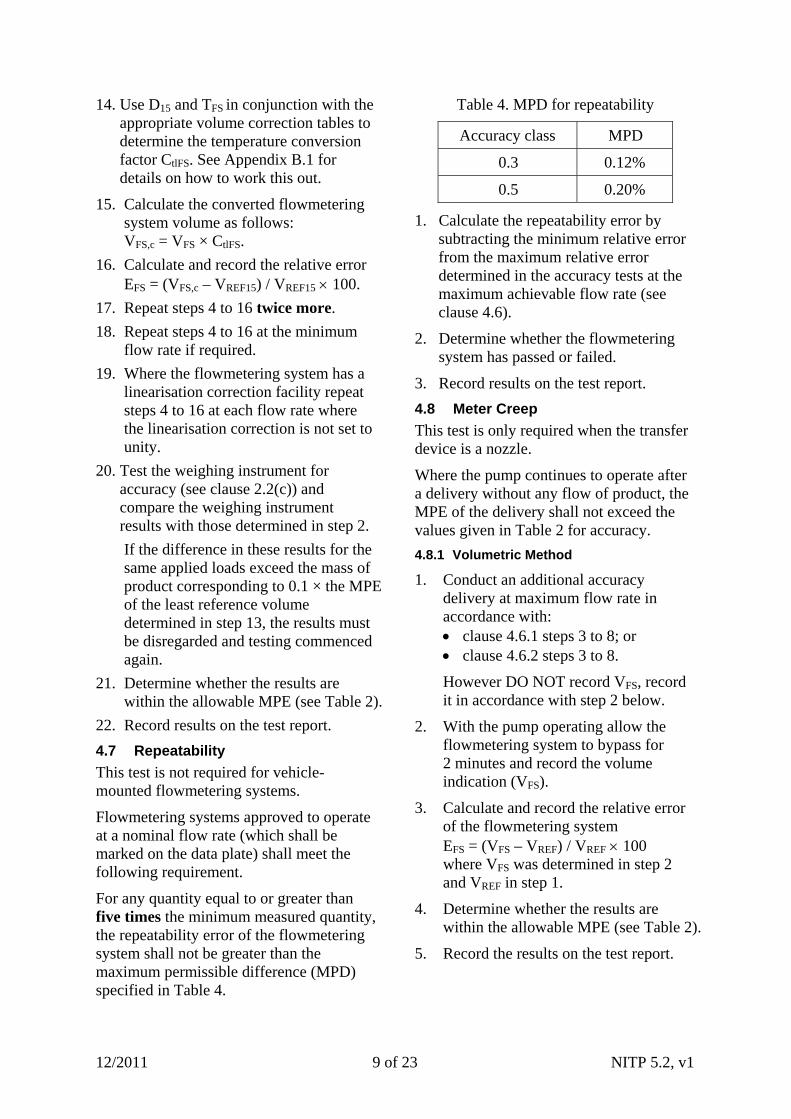
For any quantity equal to or greater than five times the minimum measured quantity, the repeatability error of the flowmetering system shall not be greater than the maximum permissible difference (MPD) specified in Table 4.
Table 4. MPD for repeatability
Accuracy class MPD
0.3 0.12%
0.5 0.20%
1. Calculate the repeatability error by subtracting the minimum relative error from the maximum relative error determined in the accuracy tests at the maximum achievable flow rate (see clause 4.6).
2. Determine whether the flowmetering system has passed or failed.
3. Record results on the test report.
4.8 Meter Creep
This test is only required when the transfer device is a nozzle.
Where the pump continues to operate after a delivery without any flow of product, the MPE of the delivery shall not exceed the values given in Table 2 for accuracy.
4.8.1 Volumetric Method
1. Conduct an additional accuracy delivery at maximum flow rate in accordance with: clause 4.6.1 steps 3 to 8; or clause 4.6.2 steps 3 to 8.
However DO NOT record VFS, record it in accordance with step 2 below.
2. With the pump operating allow the flowmetering system to bypass for 2 minutes and record the volume indication (VFS).
3. Calculate and record the relative error of the flowmetering system EFS = (VFS – VREF) / VREF 100 where VFS was determined in step 2 and VREF in step 1.
4. Determine whether the results are within the allowable MPE (see Table 2).
5. Record the results on the test report.
12/2011 9 of 23 NITP 5.2, v1
4.8.2 Gravimetric Method
1. Conduct an additional accuracy delivery at maximum flow rate in accordance with clause 4.6.3 steps 4 to 14.
2. With the pump operating allow the flowmetering system to bypass for 2 minutes and record the volume indication (VFS).
3. Use D15 and TFS in conjunction with the appropriate volume correction tables to determine the temperature conversion factor CtlFS. See Appendix B.1 for details on how to work this out.
4. Calculate the converted flowmetering system volume as follows VFS,c = VFS × CtlFS, where VFS was determined in step 2.
5. Calculate and record the relative error EFS = (VFS,c – VREF15) / VREF15 100. where VFS,c was determined in step 4 and VREF15 in step 1.
6. Determine whether the results are within the allowable MPE (see Table 2).
7. Record the results on the test report.
4.9 Conversion Device
This test is required for flowmetering systems fitted with a conversion device and is normally carried out with one of the accuracy deliveries.
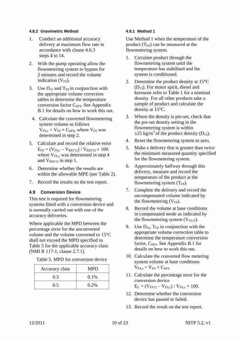
Where applicable the MPD between the percentage error for the unconverted volume and the volume converted to 15°C shall not exceed the MPD specified in Table 5 for the applicable accuracy class (NMI R 117-1, clause 2.7.1).
Table 5. MPD for conversion device
Accuracy class MPD
0.3 0.1%
0.5 0.2%
4.9.1 Method 1
Use Method 1 when the temperature of the product (TFS) can be measured at the flowmetering system.
1. Circulate product through the flowmetering system until the temperature has stabilised and the system is conditioned.
2. Determine the product density at 15°C (D15). For motor spirit, diesel and kerosene refer to Table 1 for a nominal density. For all other products take a sample of product and calculate the density at 15°C.
3. Where the density is pre-set, check that the pre-set density setting in the flowmetering system is within ±25 kg/m3 of the product density (D15).
4. Reset the flowmetering system to zero.
5. Make a delivery that is greater than twice the minimum measured quantity specified for the flowmetering system.
6. Approximately halfway through this delivery, measure and record the temperature of the product at the flowmetering system (TFS).
7. Complete the delivery and record the uncompensated volume indicated by the flowmetering (VFS).
8. Record the volume at base conditions in compensated mode as indicated by the flowmetering system (VFS15).
9. Use D15, TFS in conjunction with the appropriate volume correction table to determine the temperature conversion factor, CtlFS. See Appendix B.1 for details on how to work this out.
10. Calculate the converted flow metering system volume at base conditions VFS,c = VFS × CtlFS.
11. Calculate the percentage error for the conversion device EC = (VFS15 – VFS,c) / VFS,c × 100.
12. Determine whether the conversion device has passed or failed.
13. Record the result on the test report.
12/2011 10 of 23 NITP 5.2, v1
4.9.2 Method 2
Use Method 2 when the temperature of the product (TFS) cannot be measured at the flowmetering system.
1. Circulate product through the flowmetering system until the temperature has stabilised and the flowmetering system is conditioned.
2. Determine the product density at 15°C (D15). For motor spirit, diesel and kerosene refer to Table 1 for a nominal density. For all other products take a sample of product and calculate the density at 15°C.
3. Where the density is pre-set, check that the pre-set density setting in the flowmetering system is within ±25 kg/m3 of the product density (D15).
4. Reset the flowmetering system to zero.
5. Conduct an accuracy delivery at maximum flow rate in accordance with either: clause 4.6.1 steps 3 to 9; or clause 4.6.2 steps 3 to 9.
6. Approximately halfway through this delivery, measure and record the temperature of the product at the reference measuring equipment (TRSM,
or TMM).
7. Complete the delivery and record the uncompensated volume indicated by the flowmetering (VFS).
8. Record the volume in compensated mode as indicated by the flowmetering system (VFS15).
9. Use D15, TRSM or TMM in conjunction with the appropriate volume correction table to determine the temperature conversion factor of the reference standard (CtlRSM or CtlMM). See Appendix B.1 for details on how to work this out.
10. Calculate the converted reference standard volume at base conditions VREF15= VREF × (CtlRSM or CtlMM).
11. Calculate the percentage error for the converted delivery EFS15 = (VFS15 – VREF15) / VREF15 × 100.
12. Calculate the percentage error for the conversion device, EC = EFS15 – EFS.
EFS will be determined in step 5.
13. Determine whether the conversion device has passed or failed.
14. Record the result on the test report.
4.10 Gas Elimination Device
This test is not required where a gas elimination device is not fitted.
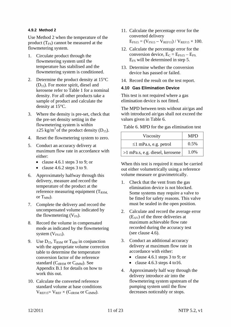
The MPD between tests without air/gas and with introduced air/gas shall not exceed the values given in Table 6.
Table 6. MPD for the gas elimination test
Viscosity MPD
1 mPa.s, e.g. petrol 0.5%
1 mPa.s, e.g. diesel, kerosene 1.0%
When this test is required it must be carried out either volumetrically using a reference volume measure or gravimetrically.
1. Check that the vent from the gas elimination device is not blocked. Some systems may require a valve to be fitted for safety reasons. This valve must be sealed in the open position.
2. Calculate and record the average error (EAV) of the three deliveries at maximum achievable flow rate recorded during the accuracy test (see clause 4.6).
3. Conduct an additional accuracy delivery at maximum flow rate in accordance with either: clause 4.6.1 steps 3 to 9; or clause 4.6.3 steps 4 to16.
4. Approximately half way through the delivery introduce air into the flowmetering system upstream of the pumping system until the flow decreases noticeably or stops.
12/2011 11 of 23 NITP 5.2, v1
5. Stop the introduction of air and complete the delivery.
6. Calculate and record the relative error EFS = (VFS – VREF) / VREF 100.
7. Determine the error for the gas elimination device, ED = EAV – EFS.
8. Determine whether the flowmetering system has passed or failed by ensuring the MPD is within the allowable limit as shown in Table 6.
9. Record results on the test report.
4.11 Low Level Cut-off
This test is a requirement at: initial verification/certification; when any system changes affecting
low level cut-off occur; and at the discretion of the trade
measurement authority.
It must be carried out either volumetrically using a reference volume measure or gravimetrically. This test may be simulated.
1. Ensure the quantity of product in the tank is above the low level cut-off device is less than the capacity of the reference volume measure.
2. Conduct an additional accuracy delivery at maximum flow rate in accordance with either: clause 4.6.1 steps 3 to 9; or clause 4.6.3 steps 4 to16.
Allow the low level cut off to automatically stop the delivery.
3. Determine whether this result is within the allowable MPE as shown in Table 2.
4. Record the results on the test report.
4.12 Pre-set Indications
A pre-set accuracy test is not required if the pre set facility is marked ‘Pre set value not for trade use’.
Flowmetering systems with a volume indicating device may also be fitted with a volume pre-setting device, which stops the flow of the liquid when the quantity corresponds to the pre-set value (NMI R 117-1, clause 3.6.10).
4.12.1 Pre-set Indications
1. Check that all pre-set buttons are operational.
2. Reset the flowmetering system to zero.
3. Condition the volume reference standard in accordance with the appropriate certificate of verification.
4. Enter a suitable pre-set value using the pre-set facility. Make sure the pre-set amount appears on the display.
5. Commence a delivery into the receiving vessel at the maximum attainable flow rate allowing the pre-set facility to slow down and complete the delivery automatically.
6. Check that the volume indication on the display corresponds exactly to the pre-set amount.
7. Determine whether the flowmetering system has passed or failed.
8. Record results on the test report.
4.12.2 Accuracy of Pre-set
1. Enter and record a suitable pre-set amount.
2. Conduct an additional accuracy delivery at maximum flow rate in accordance with: clause 4.6.1 steps 3 to 9; or clause 4.6.2 steps 3 to 9; or clause 4.6.3 steps 4 to 16.
Allow the flow control valve to stop the delivery.
3. Determine whether the results are within the allowable MPE (see Table 2).
4. Record results on the test report.
4.13 Anti-drain/Hose Dilation
This test is carried out for flowmetering systems which use a nozzle as the transfer device.
For full hoses in a measuring system provided with a hose reel, the increase in internal volume due to the change from the coiled hose position when not under
12/2011 12 of 23 NITP 5.2, v1
pressure to the uncoiled hose position when under pressure without any flow of liquid shall not exceed twice the minimum specified volume deviation (see clause 4).
If the measuring system is not provided with a hose reel, the increase in internal volume shall not exceed the minimum specified volume deviation (NMI R 117-1, clause 2.15).
Conduct the appropriate test (hose either provided without a hose reel or with a hose reel) as documented below.
4.13.1 Without a Hose Reel
1. Start a delivery to allow the hose to pressurise.
2. Stop the delivery by suddenly releasing the nozzle trigger valve.
3. Stop the flowmetering system pump.
4. Whilst holding the nozzle down, drain for 5 seconds.
5. Open the nozzle trigger valve and allow the pressure in the hose to reduce whilst draining the nozzle into a receiving vessel.
6. Close the nozzle trigger valve when the flow stops, or after 30 seconds. If product continues to leak from the nozzle after 30 seconds the nozzle trigger valve should be repaired.
7. Reset the indicator to zero.
8. Start the pump and note the increase in indication.
9. Determine whether the instrument has passed or failed by ensuring the increase in indication is within the allowable MPE.
10. Record results on the test report.
4.13.2 With a Hose Reel
1. Fully uncoil hose from its reel.
2. Start a delivery to allow the hose to pressurise.
3. Stop the delivery suddenly by releasing the nozzle trigger valve.
4. Stop the flowmetering system pump.
5. Fully coil the hose back on its reel.
6. Whilst holding the nozzle down, drain for 5 seconds.
7. Open the nozzle trigger valve and allow the pressure in the hose to reduce whilst draining the nozzle into receiving vessel.
8. Close the nozzle trigger valve when the flow stops, or after 30 seconds. If product continues to leak from the nozzle after 30 seconds the nozzle should be repaired.
9. Fully uncoil hose from its reel.
10. Reset the indicator to zero.
11. Start the pump and note the increase in indication.
12. Determine whether the instrument has passed or failed by ensuring the increase in indication is within the allowable MPE.
13. Record results on the test report.
4.14 Printing Devices
4.14.1 Discrete Ticket Printing
1. Insert a ticket.
2. Reset the indicator on the flowmetering system to zero.
3. Commence a delivery and ensure that the ticket cannot be removed.
4. Stop the delivery and print a ticket.
5. Remove the ticket and ensure printing will not occur if no ticket is present.
6. Examine the ticket to ensure that: the digits in the printing are
correctly aligned; all printings are clear, indelible and
unambiguous and include the units of measurement;
the scale interval of the printer is the same as the scale interval of the indicator;
12/2011 13 of 23 NITP 5.2, v1
the volume indicated on the ticket agrees exactly with the meter reading; and
the ticket complies with the certificate of approval or General Supplementary Certificate of Approval S1/0/A Electronic Indicating and Printing Devices for Measuring Instruments.
7. Repeat steps 1 to 6 to ensure transaction serial numbers are sequential.
8. Determine whether the ticket printing device has passed or failed.
9. Record the result on the test report and attach the tickets to the test report.
4.14.2 Continuous Ticket Printing
1. Reset the indicator on the flowmetering system to zero.
2. Commence and complete a delivery.
3. Print transaction details.
4. Examine the printed details to ensure that: the digits in the printing are
correctly aligned; all printings are clear, indelible and
unambiguous and include the units of measurement;
the scale interval of the printer is the same as the scale interval of the indicator;
the volume indicated on the transaction detail agrees exactly with the meter reading; and
the printed detail complies with the certificate of approval or General Supplementary Certificate of Approval S1/0/A Electronic Indicating and Printing Devices for Measuring Instruments.
5. Repeat steps 1 to 5 to ensure transaction serial numbers are sequential.
6. Remove the continuous feed paper and ensure printing will not occur if no paper is present.
7. Determine whether the printing device has passed or failed.
8. Record the result on the test report and attach the transaction details to the test report.
5. SUGGESTED SEQUENCE FOR TESTING
1. Where applicable, raise Australian Institute of Petroleum Work Clearance Permit.
2. Ensure all safety, environmental and site authorisations/permits have been issued.
3. Check the certificate of approval for any additional tests required. Make provision for including these tests in the testing sequence.
4. Visually inspect the flowmetering system and record the required data and characteristics of the system on the test report.
5. Conduct the indicating device test (clause 4.1).
6. Conduct an accuracy test (clause 4.6).
7. Whilst conducting the accuracy test, check: zero setting (clause 4.2);
maximum flow rate (clause 4.5);
printing device (clause 4.14); and
repeatability (clause 4.7) if applicable.
8. If required, conduct conversion device test (clause 4.9).
9. If required, conduct a gas elimination test (clause 4.10).
10. If required, conduct a low level cut-off test (clause 4.11).
11. If required, conduct an anti-drain/hose dilation test (clause 4.13).
12. If required, conduct a pre-set indication test and a pre-set volume accuracy test (clause 4.12).
12/2011 14 of 23 NITP 5.2, v1
12/2011 15 of 23 NITP 5.2, v1
13. If required, conduct a non-return valve (reverse flow) test (clause 4.3).
14. If required, conduct a meter creep test (clause 4.8).
15. If required, conduct an interlock test (clause 4.4).
16. Carry out anything else necessary to complete the procedure. This may include:
obliterating verification, certification and control marks from the flowmetering system; and
stamping the flowmetering system (for more information on stamping see General Information for Test Procedures).
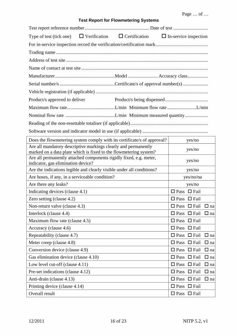
APPENDIX A. TEST REPORTS
Test reports consist of a common front page accompanied by one of the following test reports: (a) volumetric testing using a reference
volume measure; or (b) volumetric testing using a master
meter; or (c) gravimetric testing.
Although the format of the test reports may vary according to the individual needs and requirements of trade measurement authorities and licensees, the following test reports contains the minimum amount of information that must be recorded.
If the certificate of approval requires additional tests, attach pages that record the results of these tests.
Number each page of the test report in the style shown at the top of each page.
Page … of …
12/2011 16 of 23 NITP 5.2, v1
Test Report for Flowmetering Systems
Test report reference number ...................................................... Date of test .............................
Type of test (tick one) Verification Certification In-service inspection
For in-service inspection record the verification/certification mark............................................
Trading name ...............................................................................................................................
Address of test site .......................................................................................................................
Name of contact at test site ..........................................................................................................
Manufacturer..................................................Model ......................... Accuracy class.................
Serial number/s ..............................................Certificate/s of approval number(s) .....................
Vehicle registration (if applicable) ..............................................................................................
Product/s approved to deliver Product/s being dispensed....................................
Maximum flow rate........................................L/min Minimum flow rate ........................L/min
Nominal flow rate .........................................L/min Minimum measured quantity ...................
Reading of the non-resettable totaliser (if applicable).................................................................
Software version and indicator model in use (if applicable) .......................................................
Does the flowmetering system comply with its certificate/s of approval? yes/no Are all mandatory descriptive markings clearly and permanently marked on a data plate which is fixed to the flowmetering system?
yes/no
Are all permanently attached components rigidly fixed, e.g. meter, indicator, gas elimination device?
yes/no
Are the indications legible and clearly visible under all conditions? yes/no
Are hoses, if any, in a serviceable condition? yes/no/na
Are there any leaks? yes/no
Indicating devices (clause 4.1) Pass Fail
Zero setting (clause 4.2) Pass Fail
Non-return valve (clause 4.3) Pass Fail na
Interlock (clause 4.4) Pass Fail na
Maximum flow rate (clause 4.5) Pass Fail
Accuracy (clause 4.6) Pass Fail
Repeatability (clause 4.7) Pass Fail na
Meter creep (clause 4.8) Pass Fail na
Conversion device (clause 4.9) Pass Fail na
Gas elimination device (clause 4.10) Pass Fail na
Low level cut-off (clause 4.11) Pass Fail na
Pre-set indications (clause 4.12) Pass Fail na
Anti-drain (clause 4.13) Pass Fail na
Printing device (clause 4.14) Pass Fail
Overall result Pass Fail
Page … of …
12/2011 NITP 5.2, v1 17 of 23
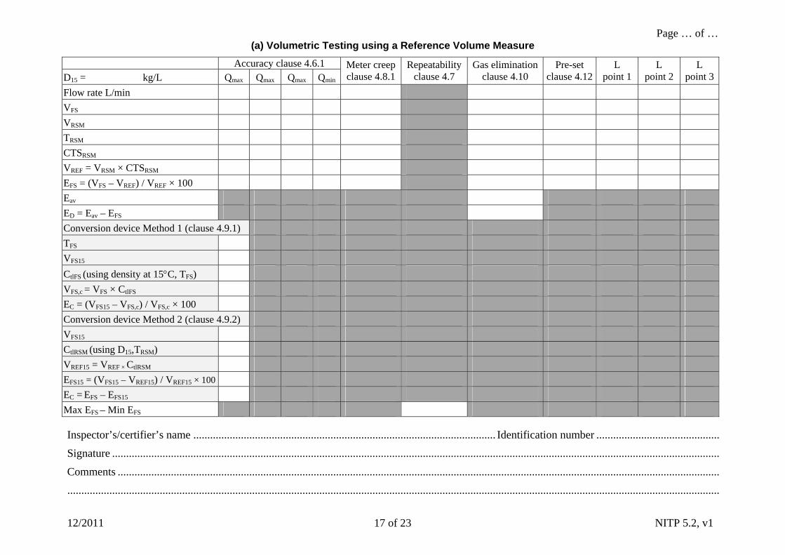
(a) Volumetric Testing using a Reference Volume Measure
Accuracy clause 4.6.1 D15 = kg/L Qmax Q Q Qmax max min
Meter creep clause 4.8.1
Repeatability clause 4.7
Gas elimination clause 4.10
Pre-set clause 4.12
L point 1
L point 2
L point 3
Flow rate L/min
VFS
VRSM
TRSM
CTSRSM
VREF = VRSM × CTSRSM
EFS = (VFS – VREF) / VREF × 100
Eav
ED = Eav – EFS
Conversion device Method 1 (clause 4.9.1)
TFS
VFS15
CtlFS (using density at 15C, TFS)
VFS,c = VFS × CtlFS
EC = (VFS15 – VFS,c) / VFS,c × 100
Conversion device Method 2 (clause 4.9.2)
VFS15
CtlRSM (using D15,TRSM)
VREF15 = VREF × CtlRSM
EFS15 = (VFS15 – VREF15) / VREF15 × 100
EC = EFS – EFS15
Max EFS – Min EFS
Inspector’s/certifier’s name ............................................................................................................ Identification number ............................................
Signature .........................................................................................................................................................................................................................
Comments .......................................................................................................................................................................................................................
.........................................................................................................................................................................................................................................
Page … of …
12/2011 NITP 5.2, v1 18 of 23
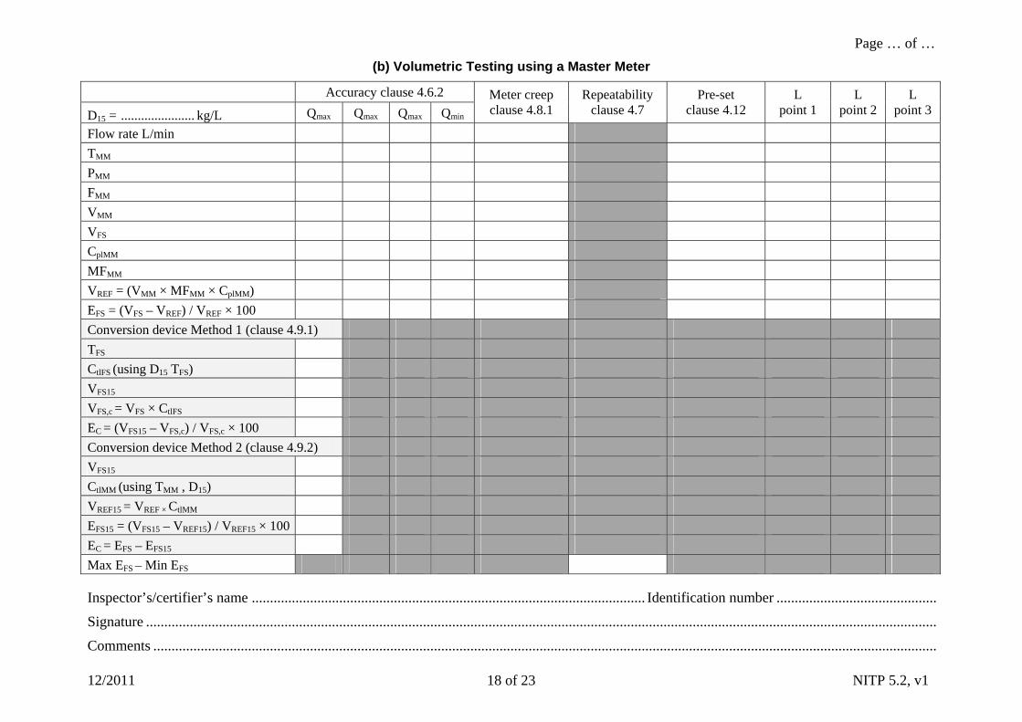
(b) Volumetric Testing using a Master Meter
Accuracy clause 4.6.2
D15 = ...................... kg/L Qmax Q Qmax max Qmin Meter creep clause 4.8.1
Repeatability clause 4.7
Pre-set clause 4.12
L point 1
L point 2
L point 3
Flow rate L/min
TMM
PMM
FMM
VMM
VFS
CplMM
MFMM
VREF = (VMM × MFMM × CplMM)
EFS = (VFS – VREF) / VREF × 100
Conversion device Method 1 (clause 4.9.1)
TFS
CtlFS (using D15 TFS)
VFS15
VFS,c = VFS × CtlFS
EC = (VFS15 – VFS,c) / VFS,c × 100
Conversion device Method 2 (clause 4.9.2)
VFS15
CtlMM (using TMM , D15)
VREF15 = VREF × CtlMM
EFS15 = (VFS15 – VREF15) / VREF15 × 100
EC = EFS – EFS15
Max EFS – Min EFS
Inspector’s/certifier’s name ............................................................................................................ Identification number ............................................
Signature .........................................................................................................................................................................................................................
Comments .......................................................................................................................................................................................................................
Page … of …
12/2011 NITP 5.2, v1 19 of 23
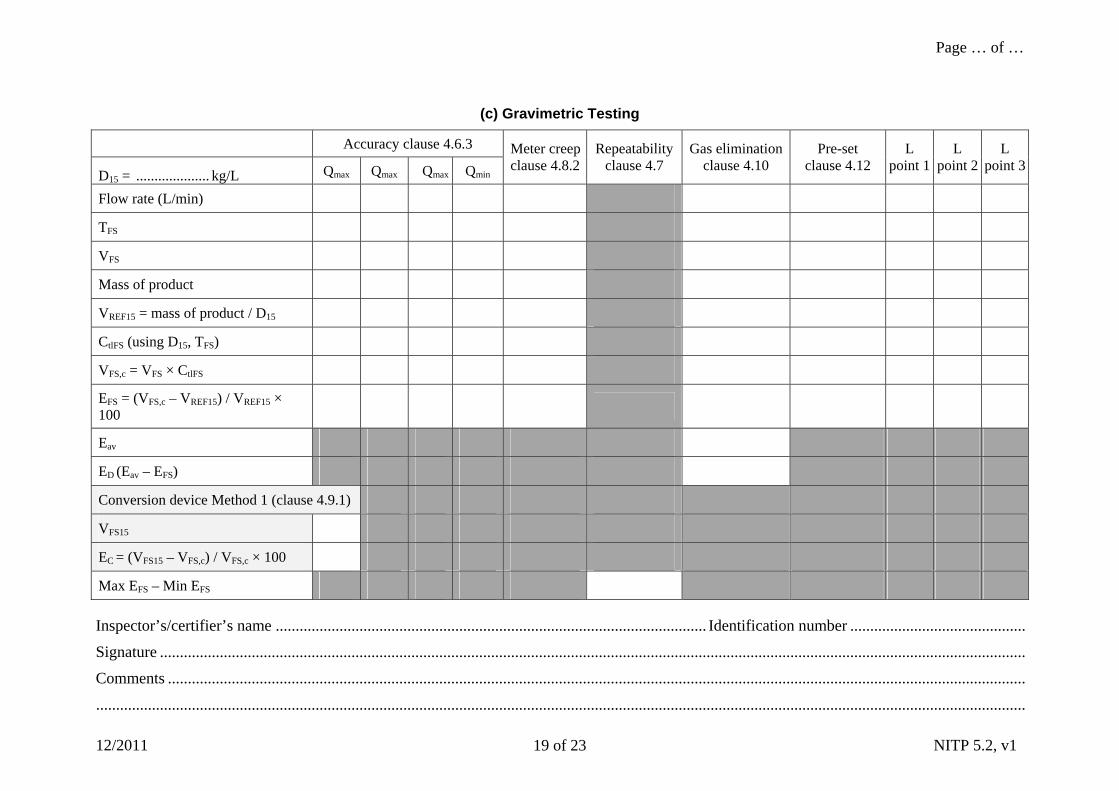
(c) Gravimetric Testing
Accuracy clause 4.6.3
D15 = .................... kg/L Qmax Q Qmax max Qmin
Meter creep clause 4.8.2
Repeatability clause 4.7
Gas elimination clause 4.10
Pre-set clause 4.12
L point 1
L point 2
L point 3
Flow rate (L/min)
TFS
VFS
Mass of product
VREF15 = mass of product / D15
CtlFS (using D15, TFS)
VFS,c = VFS × CtlFS
EFS = (VFS,c – VREF15) / VREF15 × 100
Eav
ED (Eav – EFS)
Conversion device Method 1 (clause 4.9.1)
VFS15
EC = (VFS15 – VFS,c) / VFS,c × 100
Max EFS – Min EFS
Inspector’s/certifier’s name ............................................................................................................ Identification number ............................................
Signature .........................................................................................................................................................................................................................
Comments .......................................................................................................................................................................................................................
.........................................................................................................................................................................................................................................
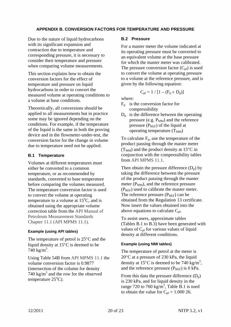
APPENDIX B. CONVERSION FACTORS FOR TEMPERATURE AND PRESSURE
Due to the nature of liquid hydrocarbons with its significant expansion and contraction due to temperature and corresponding pressure, it is necessary to consider their temperature and pressure when comparing volume measurements.
This section explains how to obtain the conversion factors for the effect of temperature and pressure on liquid hydrocarbons in order to convert the measured volume at operating conditions to a volume at base conditions.
Theoretically, all conversions should be applied to all measurements but in practice some may be ignored depending on the conditions. For example, if the temperature of the liquid is the same in both the proving device and in the flowmeter-under-test, the conversion factor for the change in volume due to temperature need not be applied.
B.1 Temperature
Volumes at different temperatures must either be converted to a common temperature, or as recommended by standards, converted to base temperature before comparing the volumes measured. The temperature conversion factor is used to convert the volume at operating temperature to a volume at 15oC, and is obtained using the appropriate volume correction table from the API Manual of Petroleum Measurement Standards Chapter 11.1 (API MPMS 11.1).
Example (using API tables)
The temperature of petrol is 25C and the liquid density at 15C is deemed to be 740 kg/m3.
Using Table 54B from API MPMS 11.1 the volume conversion factor is 0.9877 (intersection of the column for density 740 kg/m3 and the row for the observed temperature 25oC).
B.2 Pressure
For a master meter the volume indicated at its operating pressure must be converted to an equivalent volume at the base pressure for which the master meter was calibrated. The pressure conversion factor (Cpl) is used to convert the volume at operating pressure to a volume at the reference pressure, and is given by the following equation:
Cpl = 1 / [1 – (Fp Dp)]
where: Fp is the conversion factor for
compressibility Dp is the difference between the operating
pressure (e.g. PMM) and the reference pressure (PREF) of the liquid at operating temperature (TMM)
To calculate Fp, use the temperature of the product passing through the master meter (TMM) and the product density at 15C in conjunction with the compressibility tables from API MPMS 11.1.
Then obtain the pressure difference (Dp) by taking the difference between the pressure of the product passing through the master meter (PMM), and the reference pressure (PREF) used to calibrate the master meter. The reference pressure (PREF) can be obtained from the Regulation 13 certificate. Now insert the values obtained into the above equations to calculate Cpl.
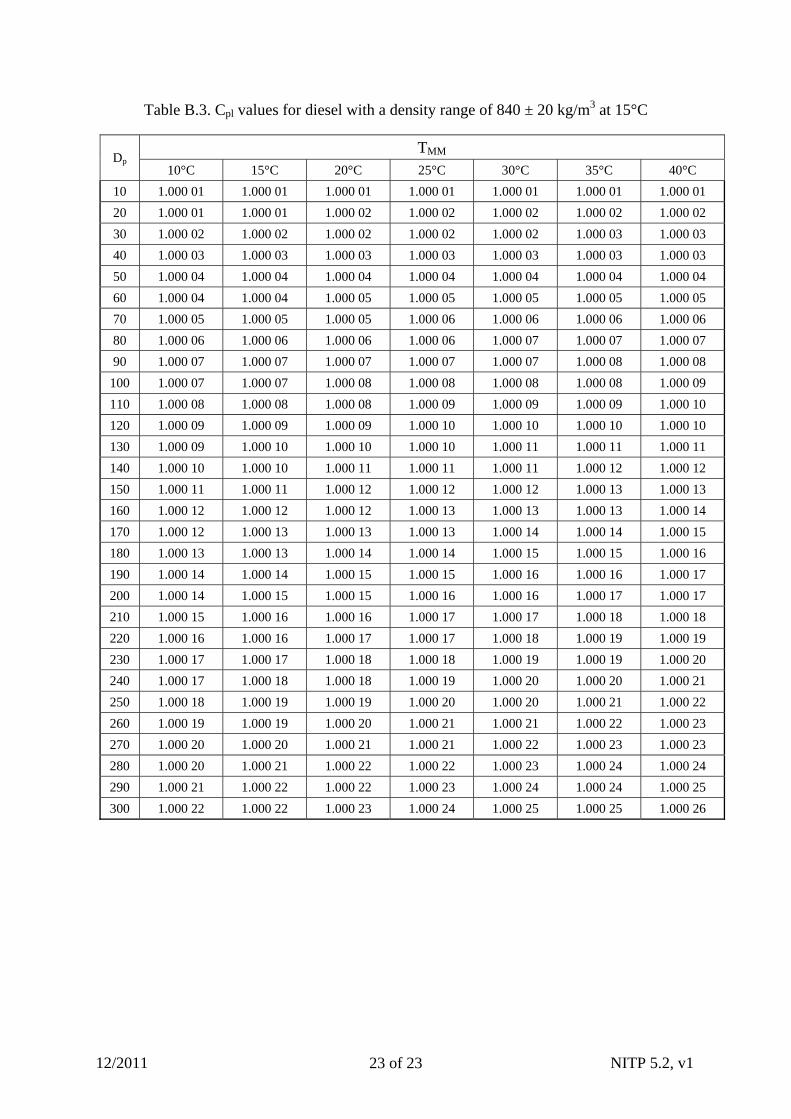
To assist users, approximate tables (Tables B.1 to B.3) have been generated with values of Cpl for various values of liquid density at different conditions.
Example (using NMI tables)
The temperature of petrol at the meter is 20C at a pressure of 230 kPa, the liquid density at 15C is deemed to be 740 kg/m3, and the reference pressure (PREF) is 0 kPa.
From this data the pressure difference (Dp) is 230 kPa, and for liquid density in the range 720 to 760 kg/m3, Table B.1 is used to obtain the value for Cpl = 1.000 26.
12/2011 NITP 5.2, v1 20 of 23
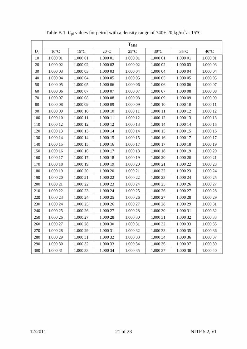
Table B.1. Cpl values for petrol with a density range of 740± 20 kg/m3 at 15°C
TMM
Dp 10°C 15°C 20°C 25°C 30°C 35°C 40°C
10 1.000 01 1.000 01 1.000 01 1.000 01 1.000 01 1.000 01 1.000 01
20 1.000 02 1.000 02 1.000 02 1.000 02 1.000 02 1.000 03 1.000 03
30 1.000 03 1.000 03 1.000 03 1.000 04 1.000 04 1.000 04 1.000 04
40 1.000 04 1.000 04 1.000 05 1.000 05 1.000 05 1.000 05 1.000 05
50 1.000 05 1.000 05 1.000 06 1.000 06 1.000 06 1.000 06 1.000 07
60 1.000 06 1.000 07 1.000 07 1.000 07 1.000 07 1.000 08 1.000 08
70 1.000 07 1.000 08 1.000 08 1.000 08 1.000 09 1.000 09 1.000 09
80 1.000 08 1.000 09 1.000 09 1.000 09 1.000 10 1.000 10 1.000 11
90 1.000 09 1.000 10 1.000 10 1.000 11 1.000 11 1.000 12 1.000 12
100 1.000 10 1.000 11 1.000 11 1.000 12 1.000 12 1.000 13 1.000 13
110 1.000 12 1.000 12 1.000 12 1.000 13 1.000 14 1.000 14 1.000 15
120 1.000 13 1.000 13 1.000 14 1.000 14 1.000 15 1.000 15 1.000 16
130 1.000 14 1.000 14 1.000 15 1.000 15 1.000 16 1.000 17 1.000 17
140 1.000 15 1.000 15 1.000 16 1.000 17 1.000 17 1.000 18 1.000 19
150 1.000 16 1.000 16 1.000 17 1.000 18 1.000 18 1.000 19 1.000 20
160 1.000 17 1.000 17 1.000 18 1.000 19 1.000 20 1.000 20 1.000 21
170 1.000 18 1.000 19 1.000 19 1.000 20 1.000 21 1.000 22 1.000 23
180 1.000 19 1.000 20 1.000 20 1.000 21 1.000 22 1.000 23 1.000 24
190 1.000 20 1.000 21 1.000 22 1.000 22 1.000 23 1.000 24 1.000 25
200 1.000 21 1.000 22 1.000 23 1.000 24 1.000 25 1.000 26 1.000 27
210 1.000 22 1.000 23 1.000 24 1.000 25 1.000 26 1.000 27 1.000 28
220 1.000 23 1.000 24 1.000 25 1.000 26 1.000 27 1.000 28 1.000 29
230 1.000 24 1.000 25 1.000 26 1.000 27 1.000 28 1.000 29 1.000 31
240 1.000 25 1.000 26 1.000 27 1.000 28 1.000 30 1.000 31 1.000 32
250 1.000 26 1.000 27 1.000 28 1.000 30 1.000 31 1.000 32 1.000 33
260 1.000 27 1.000 28 1.000 30 1.000 31 1.000 32 1.000 33 1.000 35
270 1.000 28 1.000 29 1.000 31 1.000 32 1.000 33 1.000 35 1.000 36
280 1.000 29 1.000 31 1.000 32 1.000 33 1.000 34 1.000 36 1.000 37
290 1.000 30 1.000 32 1.000 33 1.000 34 1.000 36 1.000 37 1.000 39
300 1.000 31 1.000 33 1.000 34 1.000 35 1.000 37 1.000 38 1.000 40
12/2011 NITP 5.2, v1 21 of 23
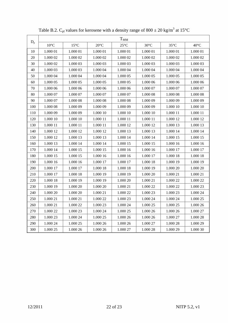
Table B.2. Cpl values for kerosene with a density range of 800 ± 20 kg/m3 at 15°C
TMM Dp
10°C 15°C 20°C 25°C 30°C 35°C 40°C
10 1.000 01 1.000 01 1.000 01 1.000 01 1.000 01 1.000 01 1.000 01
20 1.000 02 1.000 02 1.000 02 1.000 02 1.000 02 1.000 02 1.000 02
30 1.000 02 1.000 03 1.000 03 1.000 03 1.000 03 1.000 03 1.000 03
40 1.000 03 1.000 03 1.000 04 1.000 04 1.000 04 1.000 04 1.000 04
50 1.000 04 1.000 04 1.000 04 1.000 05 1.000 05 1.000 05 1.000 05
60 1.000 05 1.000 05 1.000 05 1.000 05 1.000 06 1.000 06 1.000 06
70 1.000 06 1.000 06 1.000 06 1.000 06 1.000 07 1.000 07 1.000 07
80 1.000 07 1.000 07 1.000 07 1.000 07 1.000 08 1.000 08 1.000 08
90 1.000 07 1.000 08 1.000 08 1.000 08 1.000 09 1.000 09 1.000 09
100 1.000 08 1.000 09 1.000 09 1.000 09 1.000 09 1.000 10 1.000 10
110 1.000 09 1.000 09 1.000 10 1.000 10 1.000 10 1.000 11 1.000 11
120 1.000 10 1.000 10 1.000 11 1.000 11 1.000 11 1.000 12 1.000 12
130 1.000 11 1.000 11 1.000 11 1.000 12 1.000 12 1.000 13 1.000 13
140 1.000 12 1.000 12 1.000 12 1.000 13 1.000 13 1.000 14 1.000 14
150 1.000 12 1.000 13 1.000 13 1.000 14 1.000 14 1.000 15 1.000 15
160 1.000 13 1.000 14 1.000 14 1.000 15 1.000 15 1.000 16 1.000 16
170 1.000 14 1.000 15 1.000 15 1.000 16 1.000 16 1.000 17 1.000 17
180 1.000 15 1.000 15 1.000 16 1.000 16 1.000 17 1.000 18 1.000 18
190 1.000 16 1.000 16 1.000 17 1.000 17 1.000 18 1.000 19 1.000 19
200 1.000 17 1.000 17 1.000 18 1.000 18 1.000 19 1.000 20 1.000 20
210 1.000 17 1.000 18 1.000 19 1.000 19 1.000 20 1.000 21 1.000 21
220 1.000 18 1.000 19 1.000 19 1.000 20 1.000 21 1.000 22 1.000 22
230 1.000 19 1.000 20 1.000 20 1.000 21 1.000 22 1.000 22 1.000 23
240 1.000 20 1.000 20 1.000 21 1.000 22 1.000 23 1.000 23 1.000 24
250 1.000 21 1.000 21 1.000 22 1.000 23 1.000 24 1.000 24 1.000 25
260 1.000 21 1.000 22 1.000 23 1.000 24 1.000 25 1.000 25 1.000 26
270 1.000 22 1.000 23 1.000 24 1.000 25 1.000 26 1.000 26 1.000 27
280 1.000 23 1.000 24 1.000 25 1.000 26 1.000 26 1.000 27 1.000 28
290 1.000 24 1.000 25 1.000 26 1.000 26 1.000 27 1.000 28 1.000 29
300 1.000 25 1.000 26 1.000 26 1.000 27 1.000 28 1.000 29 1.000 30
12/2011 NITP 5.2, v1 22 of 23
12/2011 NITP 5.2, v1 23 of 23
Table B.3. Cpl values for diesel with a density range of 840 ± 20 kg/m3 at 15°C
TMM Dp
10°C 15°C 20°C 25°C 30°C 35°C 40°C
10 1.000 01 1.000 01 1.000 01 1.000 01 1.000 01 1.000 01 1.000 01
20 1.000 01 1.000 01 1.000 02 1.000 02 1.000 02 1.000 02 1.000 02
30 1.000 02 1.000 02 1.000 02 1.000 02 1.000 02 1.000 03 1.000 03
40 1.000 03 1.000 03 1.000 03 1.000 03 1.000 03 1.000 03 1.000 03
50 1.000 04 1.000 04 1.000 04 1.000 04 1.000 04 1.000 04 1.000 04
60 1.000 04 1.000 04 1.000 05 1.000 05 1.000 05 1.000 05 1.000 05
70 1.000 05 1.000 05 1.000 05 1.000 06 1.000 06 1.000 06 1.000 06
80 1.000 06 1.000 06 1.000 06 1.000 06 1.000 07 1.000 07 1.000 07
90 1.000 07 1.000 07 1.000 07 1.000 07 1.000 07 1.000 08 1.000 08
100 1.000 07 1.000 07 1.000 08 1.000 08 1.000 08 1.000 08 1.000 09
110 1.000 08 1.000 08 1.000 08 1.000 09 1.000 09 1.000 09 1.000 10
120 1.000 09 1.000 09 1.000 09 1.000 10 1.000 10 1.000 10 1.000 10
130 1.000 09 1.000 10 1.000 10 1.000 10 1.000 11 1.000 11 1.000 11
140 1.000 10 1.000 10 1.000 11 1.000 11 1.000 11 1.000 12 1.000 12
150 1.000 11 1.000 11 1.000 12 1.000 12 1.000 12 1.000 13 1.000 13
160 1.000 12 1.000 12 1.000 12 1.000 13 1.000 13 1.000 13 1.000 14
170 1.000 12 1.000 13 1.000 13 1.000 13 1.000 14 1.000 14 1.000 15
180 1.000 13 1.000 13 1.000 14 1.000 14 1.000 15 1.000 15 1.000 16
190 1.000 14 1.000 14 1.000 15 1.000 15 1.000 16 1.000 16 1.000 17
200 1.000 14 1.000 15 1.000 15 1.000 16 1.000 16 1.000 17 1.000 17
210 1.000 15 1.000 16 1.000 16 1.000 17 1.000 17 1.000 18 1.000 18
220 1.000 16 1.000 16 1.000 17 1.000 17 1.000 18 1.000 19 1.000 19
230 1.000 17 1.000 17 1.000 18 1.000 18 1.000 19 1.000 19 1.000 20
240 1.000 17 1.000 18 1.000 18 1.000 19 1.000 20 1.000 20 1.000 21
250 1.000 18 1.000 19 1.000 19 1.000 20 1.000 20 1.000 21 1.000 22
260 1.000 19 1.000 19 1.000 20 1.000 21 1.000 21 1.000 22 1.000 23
270 1.000 20 1.000 20 1.000 21 1.000 21 1.000 22 1.000 23 1.000 23
280 1.000 20 1.000 21 1.000 22 1.000 22 1.000 23 1.000 24 1.000 24
290 1.000 21 1.000 22 1.000 22 1.000 23 1.000 24 1.000 24 1.000 25
300 1.000 22 1.000 22 1.000 23 1.000 24 1.000 25 1.000 25 1.000 26