Embed Size (px)
Citation preview

Nitrogen Generation SystemCustomer Product Manual
Part 1107704AIssued 5/11
NORDSON CORPORATION DULUTH, GEORGIA USAwww.nordson.com
This document contains important safety informationBe sure to read and follow all safety information in thisdocument and any other related documentation.

Part 1107704A E 2011 Nordson CorporationAll rights reserved
Nordson Corporation welcomes requests for information, comments, and inquiries about its products. General informationabout Nordson can be found on the Internet using the following address: http://www.nordson.com.
Address all correspondence to:
Nordson CorporationAttn: Customer Service11475 Lakefield DriveDuluth, GA 30097
Notice
This is a Nordson Corporation publication which is protected by copyright. Original copyright date 2011.No part of this document may be photocopied, reproduced, or translated to another language without the prior writtenconsent of Nordson Corporation. The information contained in this publication is subject to change without notice.
Trademarks
AccuJet, AeroCharge, Apogee, AquaGuard, Asymtek, Automove, Baitgun, Blue Box, Bowtie, CanWorks, Century, CF, CleanSleeve, CleanSpray,ColorMax, Color-on-Demand, Control Coat, Coolwave, Cross-Cut, cScan+, Dispensejet, DispenseMate, DuraBlue, DuraDrum, Durafiber, DuraPail,
Dura-Screen, Durasystem, Easy Coat, Easymove Plus, Ecodry, Econo-Coat, e.DOT, EFD, Emerald, Encore, ESP, e stylized, ETI - stylized, Excel 2000,Fillmaster, FlexiCoat, Flex-O-Coat, Flow Sentry, Fluidmove, FoamMelt, FoamMix, Fulfill, GreenUV, HDLV, Heli-flow, Horizon, Hot Shot, iControl, iDry, iFlow,
Isocoil, Isocore, Iso-Flo, iTRAX, Kinetix, LEAN CELL, Little Squirt, LogiComm, Magnastatic, March, Maverick, MEG, Meltex, Microcoat, Micromark,MicroSet, Millennium, Mini Squirt, Mountaingate, Nordson, OptiMix, Package of Values, Pattern View, PermaFlo, PicoDot, Porous Coat, PowderGrid,
Powderware, Precisecoat, PRIMARC, Printplus, Prism, ProBlue, Prodigy, Pro-Flo, ProLink, Pro-Meter, Pro-Stream, RBX, Rhino, Saturn, Saturn with rings,Scoreguard, Seal Sentry, Select Charge, Select Coat, Select Cure, Signature, Slautterback, Smart-Coat, Solder Plus, Spectrum, Speed-Coat, SureBead,Sure Coat, Sure-Max, Sure Wrap, Tracking Plus, TRAK, Trends, Tribomatic, TrueBlue, TrueCoat, Ultra, UpTime, u-TAH, Vantage, VersaBlue, Versa-Coat,
VersaDrum, VersaPail, Versa-Screen, Versa-Spray, Watermark, and When you expect more. are registered trademarks of Nordson Corporation.
Accubar, Advanced Plasma Systems, AeroDeck, AeroWash, AltaBlue, AltaSlot, Alta Spray, Artiste, ATS, Auto-Flo, AutoScan, Axiom, Best Choice,Blue Series, Bravura, CanPro, Champion, Check Mate, ClassicBlue, Classic IX, Clean Coat, Cobalt, Controlled Fiberization, Control Weave, ContourCoat,
CPX, cSelect, Cyclo-Kinetic, DispensLink, Dry Cure, DuraBraid, DuraCoat, DuraPUR, Easy Clean, EasyOn, EasyPW, Eclipse, e.dot+, E-Nordson,Equalizer, EquiBead, FillEasy, Fill Sentry, Flow Coat, Fluxplus, Get Green With Blue, G-Net, G-Site, iON, Iso-Flex, iTrend, Lacquer Cure, Maxima, Mesa,
MicroFin, MicroMax, Mikros, MiniBlue, MiniEdge, Minimeter, MiniPUR, Multifill, MultiScan, Myritex, Nano, OmniScan, OptiStroke, Partnership+Plus,PatternJet, PatternPro, PCI, Pinnacle, Plasmod, Powder Pilot, Powder Port, Powercure, Process Sentry, Pulse Spray, Ready Coat, RediCoat, Royal Blue,
Select Series, Sensomatic, Shaftshield, SheetAire, Smart, SolidBlue, Spectral, SpeedKing, Spray Works, Summit, SureFoam, Sure Mix, SureSeal,Swirl Coat, TAH, ThruWave, Trade Plus, Trilogy, Ultra FoamMix, UltraMax, Ultrasaver, Ultrasmart, Universal, ValueMate, Versa, Vista, Web Cure, and
2 Rings (Design) are trademarks of Nordson Corporation.
Designations and trademarks stated in this document may be brands that, when used by third parties for their own purposes,could lead to violation of the owners' rights.

Table of Contents i
Part 1107704AE 2011 Nordson Corporation
Table of ContentsSafety 1. . . . . . . . . . . . . . . . . . . . . . . . . . . . . . . . . . . . . . . . . . . . . . . . . . . . . . . .Safety Alert Symbols 1. . . . . . . . . . . . . . . . . . . . . . . . . . . . . . . . . . . . . . . . . . . .Responsibilities of the Equipment Owner 2. . . . . . . . . . . . . . . . . . . . . . . . . . .
Safety Information 2. . . . . . . . . . . . . . . . . . . . . . . . . . . . . . . . . . . . . . . . . . . .Instructions, Requirements, and Standards 2. . . . . . . . . . . . . . . . . . . . . .User Qualifications 3. . . . . . . . . . . . . . . . . . . . . . . . . . . . . . . . . . . . . . . . . . .
Applicable Industry Safety Practices 3. . . . . . . . . . . . . . . . . . . . . . . . . . . . . . .Intended Use of the Equipment 3. . . . . . . . . . . . . . . . . . . . . . . . . . . . . . . . .Instructions and Safety Messages 4. . . . . . . . . . . . . . . . . . . . . . . . . . . . . .Installation Practices 4. . . . . . . . . . . . . . . . . . . . . . . . . . . . . . . . . . . . . . . . . .Operating Practices 4. . . . . . . . . . . . . . . . . . . . . . . . . . . . . . . . . . . . . . . . . .Maintenance and Repair Practices 5. . . . . . . . . . . . . . . . . . . . . . . . . . . . . .
Equipment Safety Information 5. . . . . . . . . . . . . . . . . . . . . . . . . . . . . . . . . . . .Equipment Shutdown 6. . . . . . . . . . . . . . . . . . . . . . . . . . . . . . . . . . . . . . . . .General Safety Warnings and Cautions 7. . . . . . . . . . . . . . . . . . . . . . . . . .Other Safety Precautions 10. . . . . . . . . . . . . . . . . . . . . . . . . . . . . . . . . . . . . .First Aid 10. . . . . . . . . . . . . . . . . . . . . . . . . . . . . . . . . . . . . . . . . . . . . . . . . . . . .
Safety Labels and Tags 10. . . . . . . . . . . . . . . . . . . . . . . . . . . . . . . . . . . . . . . . .
Description 11. . . . . . . . . . . . . . . . . . . . . . . . . . . . . . . . . . . . . . . . . . . . . . . . . . .Theory of Operation 12. . . . . . . . . . . . . . . . . . . . . . . . . . . . . . . . . . . . . . . . . . . . .Key Components 13. . . . . . . . . . . . . . . . . . . . . . . . . . . . . . . . . . . . . . . . . . . . . . .Intended Use 15. . . . . . . . . . . . . . . . . . . . . . . . . . . . . . . . . . . . . . . . . . . . . . . . . .Limitations of Use 15. . . . . . . . . . . . . . . . . . . . . . . . . . . . . . . . . . . . . . . . . . . . . .
Installation 16. . . . . . . . . . . . . . . . . . . . . . . . . . . . . . . . . . . . . . . . . . . . . . . . . . .Experience of Installation Personnel 16. . . . . . . . . . . . . . . . . . . . . . . . . . . . . . .Customer-Supplied Installation Components 16. . . . . . . . . . . . . . . . . . . . . . .Mount the Generator 17. . . . . . . . . . . . . . . . . . . . . . . . . . . . . . . . . . . . . . . . . . . .Install the Booster (Optional) 18. . . . . . . . . . . . . . . . . . . . . . . . . . . . . . . . . . . . .Make the Air and Nitrogen Gas Supply Connections 20. . . . . . . . . . . . . . . . .Install Pressure Gauges As Needed 22. . . . . . . . . . . . . . . . . . . . . . . . . . . . . . .Perform Initial Startup 22. . . . . . . . . . . . . . . . . . . . . . . . . . . . . . . . . . . . . . . . . . .
Operation 23. . . . . . . . . . . . . . . . . . . . . . . . . . . . . . . . . . . . . . . . . . . . . . . . . . . . .Daily Startup and Monitoring 23. . . . . . . . . . . . . . . . . . . . . . . . . . . . . . . . . . . . .Daily Shutdown 23. . . . . . . . . . . . . . . . . . . . . . . . . . . . . . . . . . . . . . . . . . . . . . . .
Table of Contentsii
Part 1107704A E 2011 Nordson Corporation
Maintenance 24. . . . . . . . . . . . . . . . . . . . . . . . . . . . . . . . . . . . . . . . . . . . . . . . . .Recommended Maintenance Schedule 24. . . . . . . . . . . . . . . . . . . . . . . . . . . .System Pressure Relief 25. . . . . . . . . . . . . . . . . . . . . . . . . . . . . . . . . . . . . . . . . .Filter Element Replacement 26. . . . . . . . . . . . . . . . . . . . . . . . . . . . . . . . . . . . . .
Troubleshooting 28. . . . . . . . . . . . . . . . . . . . . . . . . . . . . . . . . . . . . . . . . . . . . .Nitrogen Generator Troubleshooting 28. . . . . . . . . . . . . . . . . . . . . . . . . . . . . .Booster Troubleshooting 29. . . . . . . . . . . . . . . . . . . . . . . . . . . . . . . . . . . . . . . . .
Parts 31. . . . . . . . . . . . . . . . . . . . . . . . . . . . . . . . . . . . . . . . . . . . . . . . . . . . . . . . .Using the Illustrated Parts Lists 31. . . . . . . . . . . . . . . . . . . . . . . . . . . . . . . . . . .Nitrogen Generation System Parts 32. . . . . . . . . . . . . . . . . . . . . . . . . . . . . . . .Accessories 34. . . . . . . . . . . . . . . . . . . . . . . . . . . . . . . . . . . . . . . . . . . . . . . . . . .Recommended Spare Parts 34. . . . . . . . . . . . . . . . . . . . . . . . . . . . . . . . . . . . . .
Technical Data 35. . . . . . . . . . . . . . . . . . . . . . . . . . . . . . . . . . . . . . . . . . . . . . . .Specifications 35. . . . . . . . . . . . . . . . . . . . . . . . . . . . . . . . . . . . . . . . . . . . . . . . . .Pneumatic Schematic for Optional Booster 36. . . . . . . . . . . . . . . . . . . . . . . . .
Nitrogen Generation System 1
Part 1107704AE 2011 Nordson Corporation
Nitrogen Generation System
WARNING! Allow only personnel with appropriate training and experience tooperate or service the equipment. The use of untrained or inexperiencedpersonnel to operate or service the equipment can result in injury, includingdeath, to themselves and others, and damage to the equipment.
SafetyRead this section before using the equipment. This section containsrecommendations and practices applicable to the safe installation,operation, and maintenance (hereafter referred to as “use”) of the productdescribed in this document (hereafter referred to as “equipment”). Additionalsafety information, in the form of task-specific safety alert messages,appears as appropriate throughout this document.
WARNING! Failure to follow the safety messages, recommendations, andhazard avoidance procedures provided in this document can result inpersonal injury, including death, or damage to equipment or property.
Safety Alert SymbolsThe following safety alert symbol and signal words are used throughout thisdocument to alert the reader to personal safety hazards or to identifyconditions that may result in damage to equipment or property. Comply withall safety information that follows the signal word.
WARNING! Indicates a potentially hazardous situation that, if not avoided,can result in serious personal injury, including death.
CAUTION! Indicates a potentially hazardous situation that, if not avoided,can result in minor or moderate personal injury.
CAUTION! (Used without the safety alert symbol) Indicates a potentiallyhazardous situation that, if not avoided, can result in damage to equipmentor property.

Nitrogen Generation System2
Part 1107704A E 2011 Nordson Corporation
Responsibilities of the Equipment OwnerEquipment owners are responsible for managing safety information,ensuring that all instructions and regulatory requirements for use of theequipment are met, and for qualifying all potential users.
Safety InformationS Research and evaluate safety information from all applicable sources,
including the owner-specific safety policy, best industry practices,governing regulations, material manufacturer's product information, andthis document.
S Make safety information available to equipment users in accordance withgoverning regulations. Contact the authority having jurisdiction forinformation.
S Maintain safety information, including the safety labels affixed to theequipment, in readable condition.
Instructions, Requirements, and StandardsS Ensure that the equipment is used in accordance with the information
provided in this document, governing codes and regulations, and bestindustry practices.
S If applicable, receive approval from your facility's engineering or safetydepartment, or other similar function within your organization, beforeinstalling or operating the equipment for the first time.
S Provide appropriate emergency and first aid equipment.S Conduct safety inspections to ensure required practices are being
followed.S Re-evaluate safety practices and procedures whenever changes are
made to the process or equipment.
Nitrogen Generation System 3
Part 1107704AE 2011 Nordson Corporation
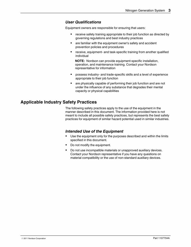
User QualificationsEquipment owners are responsible for ensuring that users:S receive safety training appropriate to their job function as directed by
governing regulations and best industry practicesS are familiar with the equipment owner's safety and accident
prevention policies and proceduresS receive, equipment- and task-specific training from another qualified
individualNOTE: Nordson can provide equipment-specific installation,operation, and maintenance training. Contact your Nordsonrepresentative for information
S possess industry- and trade-specific skills and a level of experienceappropriate to their job function
S are physically capable of performing their job function and are notunder the influence of any substance that degrades their mentalcapacity or physical capabilities
Applicable Industry Safety PracticesThe following safety practices apply to the use of the equipment in themanner described in this document. The information provided here is notmeant to include all possible safety practices, but represents the best safetypractices for equipment of similar hazard potential used in similar industries.
Intended Use of the EquipmentS Use the equipment only for the purposes described and within the limits
specified in this document.S Do not modify the equipment.S Do not use incompatible materials or unapproved auxiliary devices.
Contact your Nordson representative if you have any questions onmaterial compatibility or the use of non-standard auxiliary devices.

Nitrogen Generation System4
Part 1107704A E 2011 Nordson Corporation
Instructions and Safety MessagesS Read and follow the instructions provided in this document and other
referenced documents.S Familiarize yourself with the location and meaning of the safety warning
labels and tags affixed to the equipment. Refer to Safety Labels andTags at the end of this section.
S If you are unsure of how to use the equipment, contact your Nordsonrepresentative for assistance.
Installation PracticesS Install the equipment in accordance with the instructions provided in this
document and in the documentation provided with auxiliary devices.S Ensure that the equipment is rated for the environment in which it will be
used and that the processing characteristics of the material will notcreate a hazardous environment. Refer to the Material Safety Data Sheet(MSDS) for the material.
S If the required installation configuration does not match the installationinstructions, contact your Nordson representative for assistance.
S Position the equipment for safe operation. Observe the requirements forclearance between the equipment and other objects.
S Install lockable power disconnects to isolate the equipment and allindependently powered auxiliary devices from their power sources.
S Properly ground all equipment. Contact your local building codeenforcement agency for specific requirements.
S Ensure that fuses of the correct type and rating are installed in fusedequipment.
S Contact the authority having jurisdiction to determine the requirement forinstallation permits or inspections.
Operating PracticesS Familiarize yourself with the location and operation of all safety devices
and indicators.S Confirm that the equipment, including all safety devices (guards,
interlocks, etc.), is in good working order and that the requiredenvironmental conditions exist.
S Use the personal protective equipment (PPE) specified for each task.Refer to Equipment Safety Information or the material manufacturer'sinstructions and MSDS for PPE requirements.
S Do not use equipment that is malfunctioning or shows signs of a potentialmalfunction.

Nitrogen Generation System 5
Part 1107704AE 2011 Nordson Corporation
Maintenance and Repair PracticesS Perform scheduled maintenance activities at the intervals described in
this document.S Relieve system hydraulic and pneumatic pressure before servicing the
equipment.S De-energize the equipment and all auxiliary devices before servicing the
equipment.S Use only new Nordson-authorized refurbished or replacement parts.S Read and comply with the manufacturer's instructions and the MSDS
supplied with equipment cleaning compounds.NOTE: MSDSs for cleaning compounds that are sold by Nordson areavailable at www.nordson.com or by calling your Nordsonrepresentative.
S Confirm the correct operation of all safety devices before placing theequipment back into operation.
S Dispose of waste cleaning compounds and residual process materialsaccording to governing regulations. Refer to the applicable MSDS orcontact the authority having jurisdiction for information.
S Keep equipment safety warning labels clean. Replace worn or damagedlabels.
Equipment Safety InformationThis equipment safety information is applicable to the following types ofNordson equipment:S hot melt and cold adhesive application equipment and all related
accessoriesS pattern controllers, timers, detection and verification systems, and all
other optional process control devices

Nitrogen Generation System6
Part 1107704A E 2011 Nordson Corporation
Equipment ShutdownTo safely complete many of the procedures described in this document, theequipment must first be shut down. The level of shut down required varies bythe type of equipment in use and the procedure being completed.If required, shut down instructions are specified at the start of the procedure.The levels of shut down are:
Relieving System Hydraulic PressureCompletely relieve system hydraulic pressure before breaking any hydraulicconnection or seal. Refer to the melter-specific product manual forinstructions on relieving system hydraulic pressure.
De-energizing the SystemIsolate the system (melter, hoses, applicators, and optional devices) from allpower sources before accessing any unprotected high-voltage wiring orconnection point.1. Turn off the equipment and all auxiliary devices connected to the
equipment (system).2. To prevent the equipment from being accidentally energized, lock and
tag the disconnect switch(es) or circuit breaker(s) that provide inputelectrical power to the equipment and optional devices.NOTE: Government regulations and industry standards dictate specificrequirements for the isolation of hazardous energy sources. Refer to theappropriate regulation or standard.
Disabling the Applicators
NOTE: Adhesive dispensing applicators are referred to as “guns” in someprevious publications.
All electrical or mechanical devices that provide an activation signal to theapplicators, applicator solenoid valve(s), or the melter pump must bedisabled before work can be performed on or around an applicator that isconnected to a pressurized system.1. Turn off or disconnect the applicator triggering device (pattern controller,
timer, PLC, etc.).2. Disconnect the input signal wiring to the applicator solenoid valve(s).3. Reduce the air pressure to the applicator solenoid valve(s) to zero; then
relieve the residual air pressure between the regulator and the applicator.

Nitrogen Generation System 7
Part 1107704AE 2011 Nordson Corporation
General Safety Warnings and CautionsTable 1 contains the general safety warnings and cautions that apply toNordson hot melt and cold adhesive equipment. Review the table andcarefully read all of the warnings or cautions that apply to the type ofequipment described in this manual.
Equipment types are designated in Table 1 as follows:HM = Hot melt (melters, hoses, applicators, etc.)PC = Process controlCA = Cold adhesive (dispensing pumps, pressurized container, andapplicators)
Table 1 General Safety Warnings and Cautions
EquipmentType Warning or Caution
HM
WARNING! Hazardous vapors! Before processing any polyurethanereactive (PUR) hot melt or solvent-based material through acompatible Nordson melter, read and comply with the material'sMSDS. Ensure that the material's processing temperature andflashpoints will not be exceeded and that all requirements for safehandling, ventilation, first aid, and personal protective equipment aremet. Failure to comply with MSDS requirements can cause personalinjury, including death.
HM
WARNING! Reactive material! Never clean any aluminum componentor flush Nordson equipment with halogenated hydrocarbon fluids.Nordson melters and applicators contain aluminum components thatmay react violently with halogenated hydrocarbons. The use ofhalogenated hydrocarbon compounds in Nordson equipment cancause personal injury, including death.
HM, CAWARNING! System pressurized! Relieve system hydraulic pressurebefore breaking any hydraulic connection or seal. Failure to relieve thesystem hydraulic pressure can result in the uncontrolled release of hotmelt or cold adhesive, causing personal injury.
Continued...

Nitrogen Generation System8
Part 1107704A E 2011 Nordson Corporation
General Safety Warnings and Cautions (contd)
Table 1 General Safety Warnings and Cautions (contd)
EquipmentType Warning or Caution
HMWARNING!Molten material! Wear eye or face protection, clothing thatprotects exposed skin, and heat-protective gloves when servicingequipment that contains molten hot melt. Even when solidified, hotmelt can still cause burns. Failure to wear appropriate personalprotective equipment can result in personal injury.
HM, PC
WARNING! Equipment starts automatically! Remote triggeringdevices are used to control automatic hot melt applicators. Beforeworking on or near an operating applicator, disable the applicator'striggering device and remove the air supply to the applicator's solenoidvalve(s). Failure to disable the applicator's triggering device andremove the supply of air to the solenoid valve(s) can result in personalinjury.
HM, CA, PC
WARNING! Risk of electrocution! Even when switched off andelectrically isolated at the disconnect switch or circuit breaker, theequipment may still be connected to energized auxiliary devices.De-energize and electrically isolate all auxiliary devices beforeservicing the equipment. Failure to properly isolate electrical power toauxiliary equipment before servicing the equipment can result inpersonal injury, including death.
HM, CA, PC
WARNING! Risk of fire or explosion! Nordson adhesive equipment isnot rated for use in explosive environments and should not be usedwith solvent-based adhesives that can create an explosiveatmosphere when processed. Refer to the MSDS for the adhesive todetermine its processing characteristics and limitations. The use ofincompatible solvent-based adhesives or the improper processing ofsolvent-based adhesives can result in personal injury, including death.
Continued...

Nitrogen Generation System 9
Part 1107704AE 2011 Nordson Corporation
Table 1 General Safety Warnings and Cautions (contd)
EquipmentType Warning or Caution
HM, CA, PCWARNING! Allow only personnel with appropriate training andexperience to operate or service the equipment. The use of untrainedor inexperienced personnel to operate or service the equipment canresult in injury, including death, to themselves and others and candamage to the equipment.
HMCAUTION! Hot surfaces! Avoid contact with the hot metal surfaces ofapplicators, hoses, and certain components of the melter. If contactcan not be avoided, wear heat-protective gloves and clothing whenworking around heated equipment. Failure to avoid contact with hotmetal surfaces can result in personal injury.
HM
CAUTION! Some Nordson melters are specifically designed toprocess polyurethane reactive (PUR) hot melt. Attempting to processPUR in equipment not specifically designed for this purpose candamage the equipment and cause premature reaction of the hot melt.If you are unsure of the equipment's ability to process PUR, contactyour Nordson representative for assistance.
HM, CA
CAUTION! Before using any cleaning or flushing compound on or inthe equipment, read and comply with the manufacturer's instructionsand the MSDS supplied with the compound. Some cleaningcompounds can react unpredictably with hot melt or cold adhesive,resulting in damage to the equipment.
HM
CAUTION! Nordson hot melt equipment is factory tested with NordsonType R fluid that contains polyester adipate plasticizer. Certain hotmelt materials can react with Type R fluid and form a solid gum thatcan clog the equipment. Before using the equipment, confirm that thehot melt is compatible with Type R fluid.

Nitrogen Generation System10
Part 1107704A E 2011 Nordson Corporation
Other Safety PrecautionsS Do not use an open flame to heat hot melt system components.S Check high pressure hoses daily for signs of excessive wear, damage, or
leaks.S Never point a dispensing handgun at yourself or others.S Suspend dispensing handguns by their proper suspension point.
First AidIf molten hot melt comes in contact with your skin:1. Do NOT attempt to remove the molten hot melt from your skin.2. Immediately soak the affected area in clean, cold water until the hot melt
has cooled.3. Do NOT attempt to remove the solidified hot melt from your skin.4. In case of severe burns, treat for shock.5. Seek expert medical attention immediately. Give the MSDS for the hot
melt to the medical personnel providing treatment.
Safety Labels and TagsThere are no safety labels or tags on the equipment.

Nitrogen Generation System 11
Part 1107704AE 2011 Nordson Corporation
DescriptionThis manual describes the installation and use of the Nordson Corporationnitrogen generation system. When necessary, the reader is referred to thedocumentation supplied with other Nordson products or products suppliedby third parties.
The nitrogen generation system produces nitrogen gas from compressed air.The system may be used with any foam system or added to any applicationthat requires a nitrogen blanket. The system includes the nitrogen generator.An optional booster capable of boosting lower pressure nitrogen to arequired pressure is also available.
1
2
Figure 1 Nitrogen generator system
1. Nitrogen generator 2. Optional booster

Nitrogen Generation System12
Part 1107704A E 2011 Nordson Corporation
Theory of OperationThe generator is self-contained and consists of the following maincomponents:S a dual-stage filtering sectionS a nitrogen membrane assemblyS a precision orificeS an output accumulator
The dual stage filter removes unwanted debris, moisture, and trace oil vaporfrom the supply air. Both filter stages are equipped with high capacity floatdrains for automatic moisture removal, a pressure relief valve, and aone-quarter turn bayonet bowl closure for easy filter element replacementwithout the need for tools. The first stage filter also has a differential pressureindicator to signal filter changes.
The nitrogen membrane separates the incoming supply air, allowing nitrogengas to pass through while filtering out unwanted gasses. This results in acontinuous flow of a dry nitrogen gas supply at a purity level of95-99.5 percent.
The precision orifice controls the flow rate of gas through the generator tomaintain purity. The maximum flow rate for this combination is approximately137 l/hr.
The output accumulator helps stabilize the pressure of the nitrogen gasoutput for varying gas flow rates.
The nitrogen generation system may be operated independently to producenitrogen to a pressure of up to 7 bar (100 psi). An optional booster isavailable for higher pressure requirements. The booster is capable ofboosting pressures up to 138 bar (2,000 psi).

Nitrogen Generation System 13
Part 1107704AE 2011 Nordson Corporation
Key Components
1
6
5
8
2
4
7
3
Figure 2 Key components of the nitrogen generator
1. Output accumulator2. Orifice3. Air inlet port4. Filter status window
5. Mounting base (used to mount thegenerator)
6. Nitrogen filter housing, first stage7. Nitrogen filter housing, second
stage
8. Cover

Nitrogen Generation System14
Part 1107704A E 2011 Nordson Corporation
Key Components (contd)
12
3
4
5 6¼NPT ¼NPT
½ NPTFigure 3 Key components of the optional booster
1. On/off switch2. Nitrogen-out pressure gauge
3. Air regulator and gauge4. Air supply inlet
5. GAS IN nitrogen inlet port[109 bar (1,600 psi)maximum]
6. GAS OUT nitrogen outlet port[138 bar (2,000 psi)maximum]
Nitrogen Generation System 15
Part 1107704AE 2011 Nordson Corporation
Intended UseThe nitrogen generation system is specifically designed to:S generate nitrogen gas from compressed airS be used with compatible equipment manufactured by Nordson
CorporationS be used in non-explosive environments
Limitations of UseUse the nitrogen generation system only for the purpose for which it isdesigned. The system should not be used:S in an environment in which the ambient temperature is too low or too
high; for safe operation, the ambient temperature must remainbetween 2-50 _C (36-122 _F)
S in an area in where organic solvent vapors could enter thecompressed air supply
S in applications that exceed the nitrogen flow rate capability of thegenerator (>137 l/hr)

Nitrogen Generation System16
Part 1107704A E 2011 Nordson Corporation
InstallationInstallation includes mounting the system components, connecting airsupplies, and adjusting air pressures.
Experience of Installation PersonnelThe instructions provided in this section are intended to be used bypersonnel who have experience in the following subjects:S Hot melt application processesS Industrial mechanical installation practices
Customer-Supplied Installation ComponentsIn addition to the components provided by Nordson Corporation, installationof the nitrogen generation system requires the following customer-suppliedcomponents:S a clean, dry, regulated, unlubricated compressed air supplyS air pressure regulator and filter in the air supplyS 1/4-in. air supply tubingS if installing the booster, items listed underMount the Booster
(Optional)
Nitrogen Generation System 17
Part 1107704AE 2011 Nordson Corporation
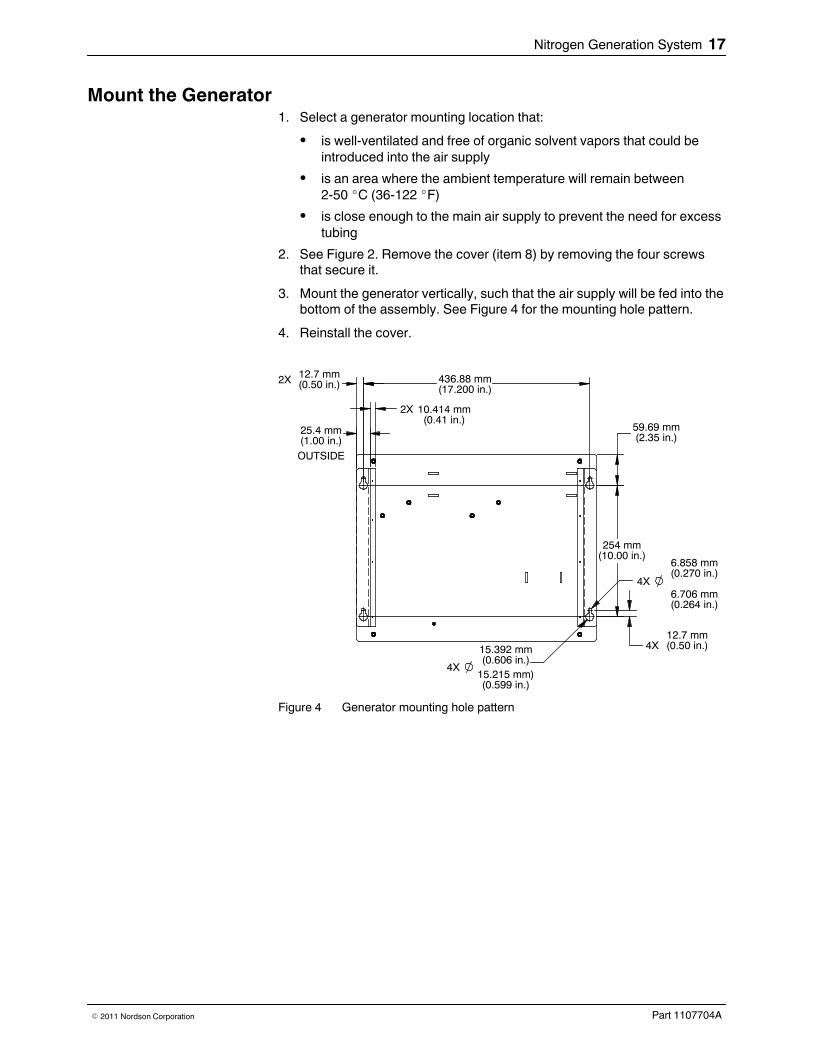
Mount the Generator1. Select a generator mounting location that:S is well-ventilated and free of organic solvent vapors that could be
introduced into the air supplyS is an area where the ambient temperature will remain between
2-50 _C (36-122 _F)S is close enough to the main air supply to prevent the need for excess
tubing2. See Figure 2. Remove the cover (item 8) by removing the four screws
that secure it.3. Mount the generator vertically, such that the air supply will be fed into the
bottom of the assembly. See Figure 4 for the mounting hole pattern.4. Reinstall the cover.
4X
OUTSIDE
2X
(0.50 in.)2X 12.7 mm(17.200 in.)436.88 mm
(0.41 in.)10.414 mm
(2.35 in.)59.69 mm
(1.00 in.)25.4 mm
(0.606 in.)15.392 mm
(0.599 in.)15.215 mm)
(10.00 in.)254 mm
(0.270 in.)6.858 mm
(0.264 in.)6.706 mm
4X
(0.50 in.)4X12.7 mm
Figure 4 Generator mounting hole pattern

Location of the 1/4 NPT GAS INand GAS OUT ports on the booster
Nitrogen Generation System18
Part 1107704A E 2011 Nordson Corporation
Install the Booster (Optional)CAUTION! The customer supplied nitrogen supply must be complete withshutoff valves, pressure gauges, pressure regulators, and -6 hoseassemblies. These components must be rated for 344.7 bar (5,000 psi)operation.
You will need the following items to install the booster:S one 1/4 NPT quick-disconnect tubing fittingS one AN816-6, 3/8-in. AN to 1/4-in. male pipe adapter (refer to Parts) S one stainless-steel/PTFE -6 hose assemblies rated to 344.7 bar
(5,000 psi) working pressure S PTFE pipe tape
1. If desired, mount the booster to a bracket or cart using the three 1/4-20 by1/2-in. deep-tapped holes provided.
2. Remove the protective plastic plugs from the GAS IN and GAS OUTports.
3. Insert the 1/4 NPT quick-disconnect tubing fitting in the GAS IN port.4. Wrap 2-3 turns of PTFE tape clockwise around the pipe thread end of
the male pipe adapter.5. Insert the male pipe adapter in the GAS OUT port and firmly tighten,
being careful not to over-tighten.6. Connect the -6 swivel hose to the male pipe adapter extending from the
GAS OUT port. Connect the other end of the hose to the foam processequipment.
7. Check all components for integrity.

Nitrogen Generation System 19
Part 1107704AE 2011 Nordson Corporation
This page intentionally left blank.

Nitrogen Generation System20
Part 1107704A E 2011 Nordson Corporation
Make the Air and Nitrogen Gas Supply ConnectionsSee Figure 5. Make the air and nitrogen gas supply connections shown inTable 2. The air supply must be clean, dry, regulated, unlubricatedcompressed air.
Table 2 Nitrogen Generation System Air and Nitrogen Gas Connections
ConnectionShown inFig. 5
Connection Connect to... Then connect to...
A Main air supply to thenitrogen generator and (ifused) to the booster
Main air supply AIR IN port on the nitrogengeneratorand (if used)Air input port on the booster
B Nitrogen gas supply to thebooster (if used) or otherequipment, as applicable
NITROGEN OUT port onnitrogen generator
GAS IN male pipe adapteron boosterornitrogen input port for thenitrogen blanket

Nitrogen Generation System 21
Part 1107704AE 2011 Nordson Corporation
B
NITROGEN GENERATOR
MAIN AIRSUPPLY
A
BOOSTER
1
(OPTIONAL)
EQUIPMENT USING
NITROGEN GENERATOR
4
5
3
2
HIGH PRESSUREFOR FOAMING PROCESS
EQUIPMENT USINGNITROGEN BLANKET
6
¼ in.
¼ in.
Figure 5 Air supply and nitrogen connections (refer to Table 2)
1. Location of the air input port on thenitrogen generator
2. Nitrogen generator3. Main air supply
4. Booster (optional)5. Equipment using high pressure for
the foaming process
6. Equipment using a nitrogenblanket
Note: See Figure 3, item 4, for the location of the air input port on the booster.Note: Refer to Parts for additional accessories available for the nitrogen blanket and foaming processes.

Booster PUMP RUN switch
Nitrogen Generation System22
Part 1107704A E 2011 Nordson Corporation
Install Pressure Gauges As NeededInstall pressure gauges as desired so that full system depressurization canbe verified prior to service activities.
Perform Initial Startup1. Turn on the air supply to the nitrogen generator.2. Verify that gas is being delivered from the NITROGEN OUT port on the
generator.3. If the optional booster was installed:
a. Turn on the air supply to the booster.b. Place the booster PUMP RUN switch in the ON position.c. Adjust the booster air regulator. If the booster pump strokes and the
booster pressure gauge responds, then the booster is operatingproperly.
4. Verify that the nitrogen gas blanket is operating properly on the receivingequipment.
The system is ready for routine operation.

Booster PUMP RUN switch
FILTER STATUS indicator
Nitrogen Generation System 23
Part 1107704AE 2011 Nordson Corporation
OperationBefore operating the system for the first time, ensure that you havecompleted the procedures under Installation.
Daily Startup and Monitoring1. Turn on the air supply to the nitrogen generator and, if used, the booster.2. If applicable, place the booster PUMP RUN switch in the ON position.3. Verify that the correct system pressures have been obtained. Make
adjustments as needed.4. Ensure that automatic drains and filters are functioning properly.
CAUTION! Risk of equipment damage. Do not operate the nitrogengeneration system if the FILTER STATUS indicator needle is in theCHANGE area. Doing so may damage the nitrogen membrane.
5. Check the FILTER STATUS indicator. If the needle is in the CHANGEarea, replace the nitrogen filter elements. Refer to Filter ElementReplacement underMaintenance.
Daily Shutdown1. If desired, reduce or turn off the air supply and relieve system pressure.
Refer to System Pressure Relief underMaintenance as needed.2. If applicable, place the booster PUMP RUN switch in the OFF position.

Nitrogen Generation System24
Part 1107704A E 2011 Nordson Corporation
MaintenanceThis section contains a recommended maintenance schedule andprocedures. Attempting any other maintenance procedures can result inequipment damage, improper system operation, or personal injury.
Recommended Maintenance ScheduleTable 3 provides recommended maintenance activities and a schedule forperforming those activities. Base how often you perform maintenance onyour operating conditions.
Table 3 Recommended MaintenanceActivity Interval Procedure
Inspect forexternal damage
Daily When damaged parts pose a risk to the operationalsafety of the unit and/or safety of personnel, switch off thesystem and have the damaged parts replaced byqualified personnel. Use only original Nordson spareparts.
Clean the exterior Daily Remove dust, flakes, etc. with a vacuum cleaner or a softcloth.
Replace thenitrogen filterelements
When the FILTERSTATUS needleindicates CHANGEorevery six months,whichever comes first
Refer to Filter Element Replacement in this section.
Service the aircompressor ormain air supply
As needed Refer to the air supply documentation.

GAS OUT fitting location onbooster
Nitrogen Generation System 25
Part 1107704AE 2011 Nordson Corporation
System Pressure ReliefSystem pressure must be relieved before you can safely proceed with manytroubleshooting and service-related activities for equipment used with thenitrogen generation system. Follow this procedure whenever you need torelieve system pressure.
CAUTION! Risk of pressure buildup. The nitrogen generation system ispressurized when operating. Depresserization may take some time after theair supply is shut off. Before servicing any equipment used with the nitrogengeneration system, ensure that the system is fully depressurized.
NOTE: Always depressurize the generator before depressurizing thebooster, if present.1. Shut off the main air supply or set the air pressure regulator to zero (0).2. If the booster is present:
a. Loosen the GAS OUT hose fitting and allow the nitrogen pressure tobleed off.
b. Ensure that the booster pressure gauge reads zero (0).c. Tighten the fitting.
3. When the service activity is completed, restore the system to normaloperation.

Nitrogen Generation System26
Part 1107704A E 2011 Nordson Corporation
Filter Element ReplacementThe nitrogen filter elements should be replaced when either of the followingconditions occurs:S the FILTER STATUS needle indicates CHANGES every six months (even if the FILTER STATUS needle does not
indicate CHANGE)Always replace both filter elements. Refer to Parts for the filter element kitpart numbers.1. Relieve system pressure. Refer to System Pressure Relief earlier in this
section as needed.2. See Figure 6. Remove the filter housings by turning them ¼-turn
counterclockwise.NOTE: It is not necessary to remove the cover for this procedure.
Figure 6 Removing the filter elements (generator shown with cover removed)

Nitrogen Generation System 27
Part 1107704AE 2011 Nordson Corporation
3. Grasp the filter element and pull it straight down to remove it from thehousing.
4. Install new filter elements in the housings.5. See Figure 7. Install the housings, turning them ¼-turn clockwise to
secure them. Ensure that the stage 1 and stage 2 filters are installed inthe correct order, as shown in Figure 7.
6. Restore the system to normal operation.
P/N 1106793 P/N 1106794
Figure 7 Installing filter elements

Nitrogen Generation System28
Part 1107704A E 2011 Nordson Corporation
TroubleshootingThis section covers only the most common problems you may encounter. Ifyou cannot solve a problem with the information given here, contact yourlocal Nordson representative for help.
For additional troubleshooting information, refer to the manuals provided withthe other equipment used in the system.
Nitrogen Generator Troubleshooting
Problem Possible Cause Corrective Action1. Low air supply
pressureInlet air pressure too low Ensure that the air supply pressure is
greater than 4 bar (60 psi).Check for leaks.
2. Low nitrogen supplypressure
Obstructed filter(s) Check for obstructed filters. Replacethe filter elements or filter assembliesas needed. Refer to Filter ElementReplacement underMaintenance asneeded.
Low air supply pressure Ensure that the air supply pressure isgreater than 4 bar (60 psi).Check for leaks.
Blocked orifice Clean or replace the orifice.Obstructed nitrogen membraneassembly
Replace the assembly.

Nitrogen Generation System 29
Part 1107704AE 2011 Nordson Corporation
Booster Troubleshooting
Problem Possible Cause Corrective Action1. Pump will not cycle
(only regulatednitrogen pressure atoutput)
No air supply to pump Check the air supply and resolveissues.
Pump regulator set too low Increase the setting.2. Pump will still not
cycle (only regulatednitrogen pressure atoutput)
Four way air reciprocating valvespool stuck at mid-position
Disconnect and then reconnect theair supply (this will reset the air spoolto the end position).If the spool still sticks, manually pushthe spool to the far end by inserting aprobe through the hole in the spoolstop cap. If the spool is stuck orrequires excessive force,disassemble the air valve assembly.Inspect for contamination ormechanical bind. Repair or replace asneeded, lubricating the seals withwaterproof grease.
3. Pump makes onecycle, then stops
Faulty 2-way air valve (broken,leaks, or contaminated)
Repair or replace.
4. Pump cyclesconstantly whendead-headed
External leak at pump or indownstream high pressure circuit
Check for leaks and resolve issues.
Check valve cartridgecontaminated or stuck open
Clean or replace.
Internal leak in pump Check all dynamic and static sealsand gaskets and replace as needed.

Nitrogen Generation System30
Part 1107704A E 2011 Nordson Corporation
This page intentionally left blank.

Nitrogen Generation System 31
Part 1107704AE 2011 Nordson Corporation
PartsTo order parts, call the Nordson Customer Service Center or your localNordson representative. Use these five-column parts lists, and theaccompanying illustrations, to describe and locate parts correctly. Thefollowing chart provides guidance for reading the parts lists.
Using the Illustrated Parts Lists
The number in the Item column corresponds to the circled item numberin the parts list illustration. A dash in this column indicates that the itemis an assembly.
The number in the Part column is the Nordson part numberyou can use to order the part. A series of dashes indicatesthat the part is not saleable. In this case, you must ordereither the assembly in which the part is used or a service kitthat includes the part.
The Description column describes the part andsometimes includes dimensions or specifications.
The Note column contains letters that refer to notes atthe bottom of the parts list. These notes provideimportant information about the part.
The Quantity column tells you how many of thepart is used to manufacture the assembly shown inthe parts list illustration. A dash or AR in thiscolumn indicates that the amount of the itemrequired in the assembly is not quantifiable.
Item Part Description Quantity Note— 0000000 Assembly A —1 000000 S Part of assembly A 2 A2 - - - - - - S S Part of item 1 13 0000000 S S S Part of item 2 ARNS 000000 S S S S Part of item 3 2
NOTE A: Important information about item 1AR: As RequiredNS: Not Shown

Nitrogen Generation System32
Part 1107704A E 2011 Nordson Corporation
Nitrogen Generation System PartsSee Figures 8-9.
Item Part Description Quantity Note— 1106554 NITROGEN GENERATOR —1 1105774 S MODULE,NITROGEN,14.7 X 1.6 DIA. 12 - - - - - - S CLAMP,HOSE/TUBE,1 5/16 TO 2 1/4 23 971266 S ELBOW,MALE,.25 TUBE X .25 NPT 54 971265 S CONN,MALE,1/4TUBEX1/4NPT 35 188734 S TUBING,FLOUROPOLYMER,TFE 16 - - - - - - S BRACKET,MOUNTING,FILTER 27 - - - - - - S SCREW,SKT HD,M5 X 10,STL,ZN PL 88 1105772 S FILTER,1ST STAGE,NITRO MODULE 1 A9 1105773 S FILTER,2ND STAGE,NITRO MODULE 1 B10 - - - - - - S HOUSING, W/FILTER CARTRIDGE,125 PSIG 111 1106516 S ADAPTER.RESTRICTOR,.007 ORIFICE 112 - - - - - - S COVER,NITROGEN,KIT 113 - - - - - - S PANEL,MOUNTING,NITROGEN KIT 114 - - - - - - S CLAMP,HOSE/TUBE,3.00 115 1105945 AMPLIFIER,BOOSTER,AIR/NITROGEN 1 CNS 713411 S CONN, MALE, 37, 7/16-20, ¼, SSTL 1 D
NOTE A: To replace the filter element, order kit part number 1107458 (contains four first-stage filter elements).B: To replace the filter element, order kit part number 1107459 (contains four second-stage filter elements).C: The booster is optional.D: Refer to Install the Booster (Optional) under Installation for the use of this fitting.
NS: Not Shown
7
12
15
Figure 8 Nitrogen generator parts (1 of 2)

Nitrogen Generation System 33
Part 1107704AE 2011 Nordson Corporation
8
1
2 2
143
3
3
3 4
4
5
5
5
6
7
3
9
10
11
4
( FILTER WITH SIGHT GLASS )13
Figure 9 Nitrogen generator parts (2 of 2)
Nitrogen Generation System34
Part 1107704A E 2011 Nordson Corporation
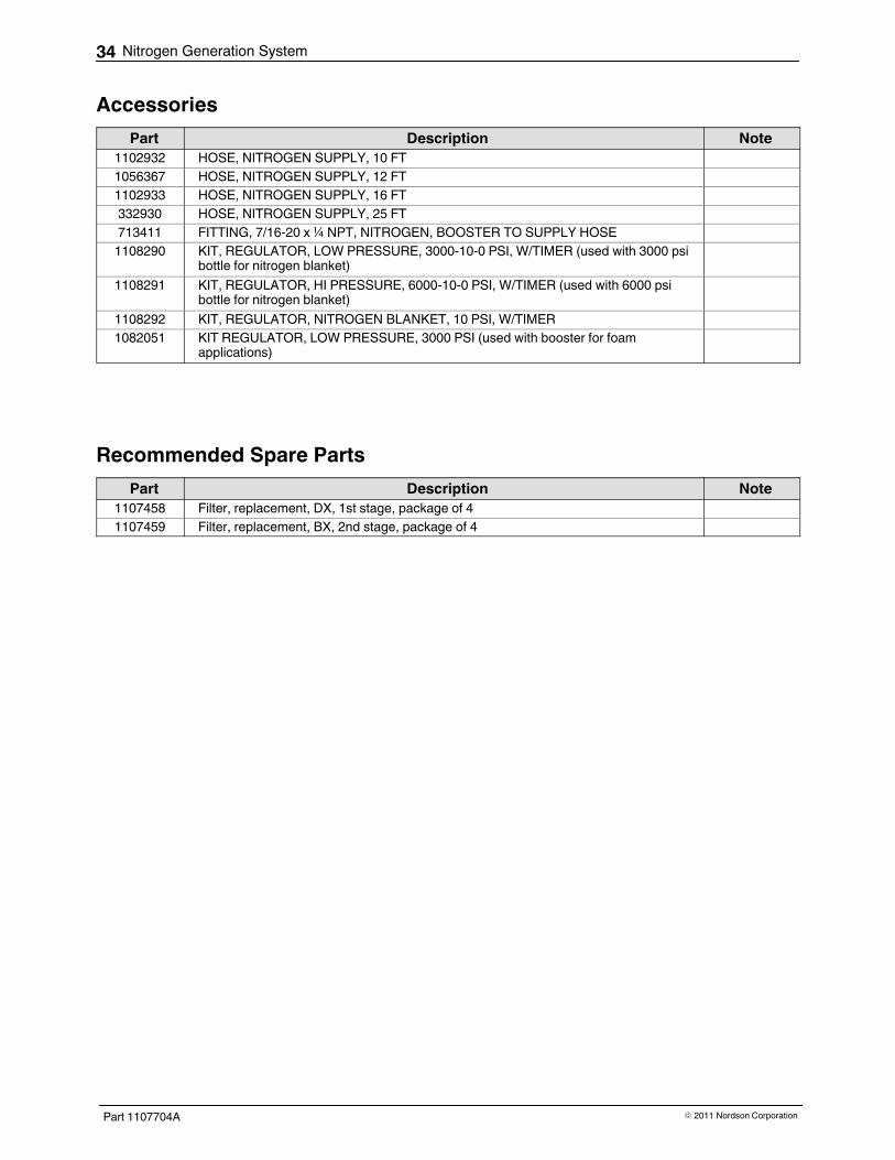
AccessoriesPart Description Note
1102932 HOSE, NITROGEN SUPPLY, 10 FT1056367 HOSE, NITROGEN SUPPLY, 12 FT1102933 HOSE, NITROGEN SUPPLY, 16 FT332930 HOSE, NITROGEN SUPPLY, 25 FT713411 FITTING, 7/16-20 x ¼ NPT, NITROGEN, BOOSTER TO SUPPLY HOSE1108290 KIT, REGULATOR, LOW PRESSURE, 3000-10-0 PSI, W/TIMER (used with 3000 psi
bottle for nitrogen blanket)1108291 KIT, REGULATOR, HI PRESSURE, 6000-10-0 PSI, W/TIMER (used with 6000 psi
bottle for nitrogen blanket)1108292 KIT, REGULATOR, NITROGEN BLANKET, 10 PSI, W/TIMER1082051 KIT REGULATOR, LOW PRESSURE, 3000 PSI (used with booster for foam
applications)
Recommended Spare PartsPart Description Note
1107458 Filter, replacement, DX, 1st stage, package of 41107459 Filter, replacement, BX, 2nd stage, package of 4

Nitrogen Generation System 35
Part 1107704AE 2011 Nordson Corporation
Technical DataSpecifications
Component Item SpecificationNitrogen generator Operating temperature Range: 2-50 _C (36-122 _F)
Recommended for optimum performance:15-25 _C (59-77 _F)
Operating pressure Recommended for optimum performance:4-9 bar (60-125 psig)
Booster Dimensions 150 mm H x 473 mm L x 361.5 mmW(5.91 in. L x 18.62 in. H x 14.23 in. W)
Weight Approximately 11 kg (25 lb)Operating pressure 35-138 bar (500-2000 psi)Nitrogen booster ratio 20:1

Nitrogen Generation System36
Part 1107704A E 2011 Nordson Corporation
Pneumatic Schematic for Optional Booster
FROMNITROGEN
GENERATOR
Figure 10 Booster pneumatic schematic