Embed Size (px)
Citation preview
NLDC 1
Defence plan and
System restoration
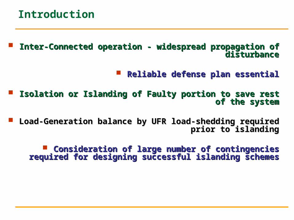
Introduction
Inter-Connected operation - widespread propagation of Inter-Connected operation - widespread propagation of disturbancedisturbance
Reliable defense plan essentialReliable defense plan essential
Isolation or Islanding of Faulty portion to save rest of the systemIsolation or Islanding of Faulty portion to save rest of the system
Load-Generation balance by UFR load-shedding required prior to Load-Generation balance by UFR load-shedding required prior to islandingislanding
Consideration of large number of contingencies required for Consideration of large number of contingencies required for designing successful islanding schemesdesigning successful islanding schemes
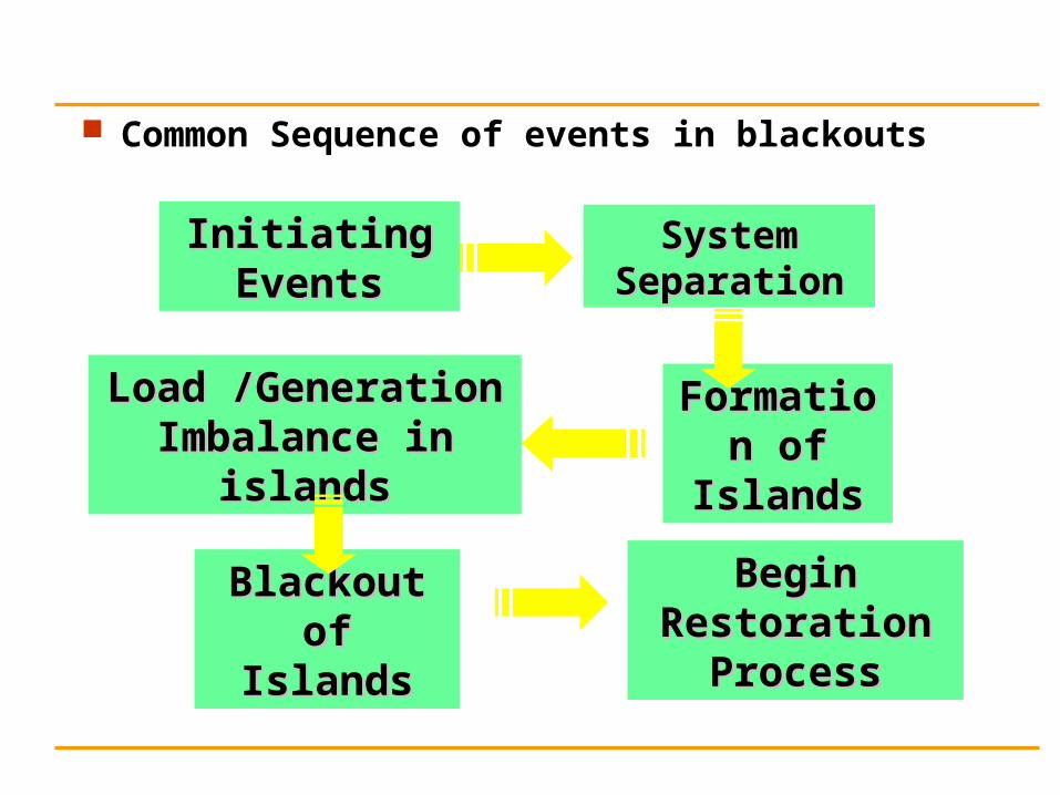
Common Sequence of events in blackouts
Initiating EventsInitiating Events
Formation of Formation of IslandsIslands
System System SeparationSeparation
Load /Generation Load /Generation Imbalance in islandsImbalance in islands
Blackout of Blackout of IslandsIslands
Begin Restoration Begin Restoration ProcessProcess
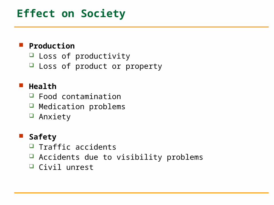
Effect on Society
Production Loss of productivity Loss of product or property
Health Food contamination Medication problems Anxiety
Safety Traffic accidents Accidents due to visibility problems Civil unrest
Public Scrutiny
Any widespread electric outage draws a lot of attention from: Politicians Governmental agencies
MOP ERCs Special interest groups
Consumer, Advocates, Environmentalists Large customers Media
Types of Blackouts
Localized Partial System Full System With Outside Help Full System Without Outside Help
Restoration strategy may be different Restoration strategy may be different for each type of outage !for each type of outage !
Blackouts
System separations and blackouts are possible at all loading levels!
System separations and blackouts are possible at all times of the day and year!
Heavily stressed system is more likely to black out!
Prevention is the key to system restoration!
Causes of Blackouts
Pre-disturbance conditions that could contribute to a system blackout: Maintenance outages Heavy/Uncontrolled loop flow through system Changing generation patterns Weather Unexpected events/FAULTS Relay mal-operation Circuit breaker failure
Causes of Blackouts
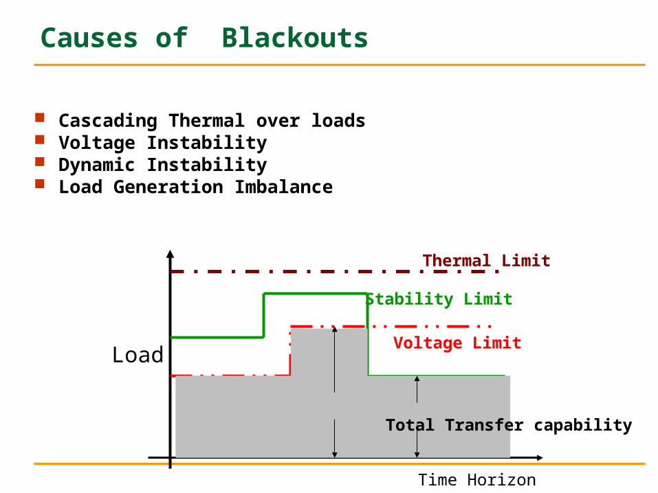
Cascading Thermal over loads Voltage Instability Dynamic Instability Load Generation Imbalance
Time Horizon
Power Flow
Thermal Limit
Voltage Limit
Stability Limit
Total Transfer capability
Load
Causes of Blackouts
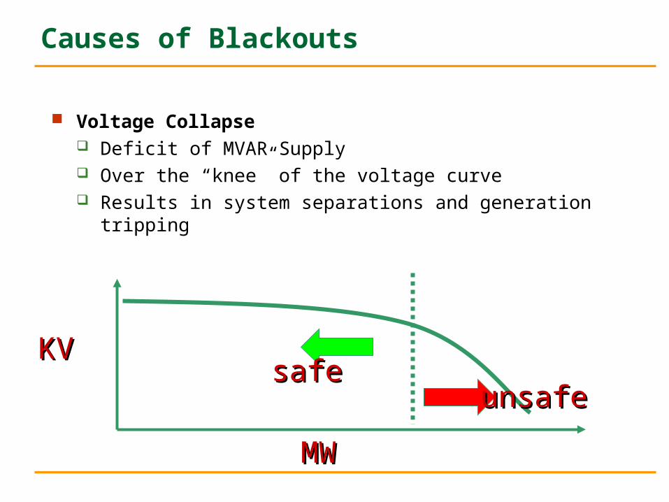
Voltage Collapse Deficit of MVAR Supply Over the “knee” of the voltage curve Results in system separations and generation tripping
KVKV
MWMW
safesafeunsafeunsafe
Causes of Blackouts
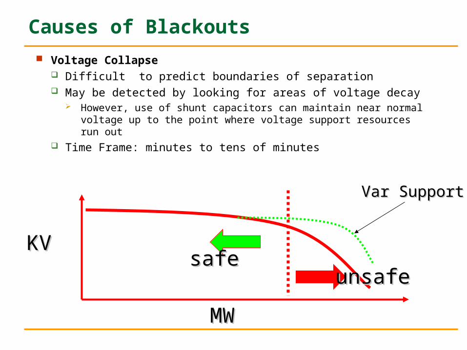
Voltage Collapse Difficult to predict boundaries of separation May be detected by looking for areas of voltage decay
However, use of shunt capacitors can maintain near normal voltage up to the point where voltage support resources run out
Time Frame: minutes to tens of minutes
KVKV
MWMW
safesafeunsafeunsafe
Var SupportVar Support
Causes of Blackouts
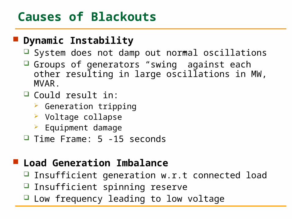
Dynamic Instability System does not damp out normal oscillations Groups of generators “swing” against each other resulting in
large oscillations in MW, MVAR. Could result in:
Generation tripping Voltage collapse Equipment damage
Time Frame: 5 -15 seconds
Load Generation Imbalance Insufficient generation w.r.t connected load Insufficient spinning reserve Low frequency leading to low voltage
SYSTEM RESTORATION
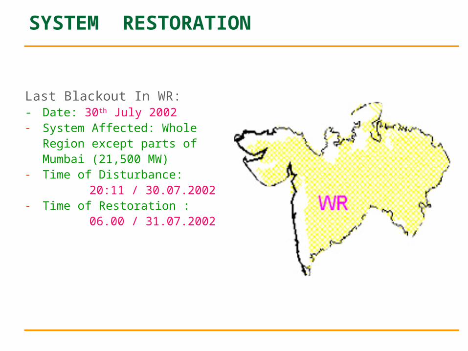
Last Blackout In WR:- Date: 30th July 2002- System Affected: Whole
Region except parts ofMumbai (21,500 MW)
- Time of Disturbance: 20:11 / 30.07.2002
- Time of Restoration : 06.00 / 31.07.2002
SYSTEM RESTORATION
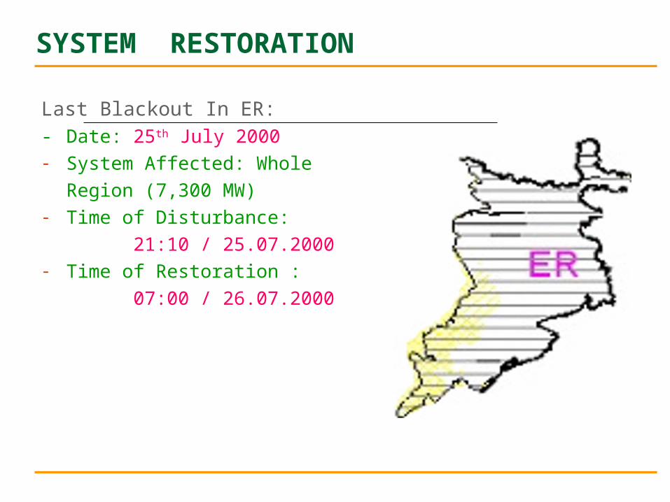
Last Blackout In ER:- Date: 25th July 2000- System Affected: Whole
Region (7,300 MW)- Time of Disturbance:
21:10 / 25.07.2000- Time of Restoration :
07:00 / 26.07.2000
SYSTEM RESTORATION
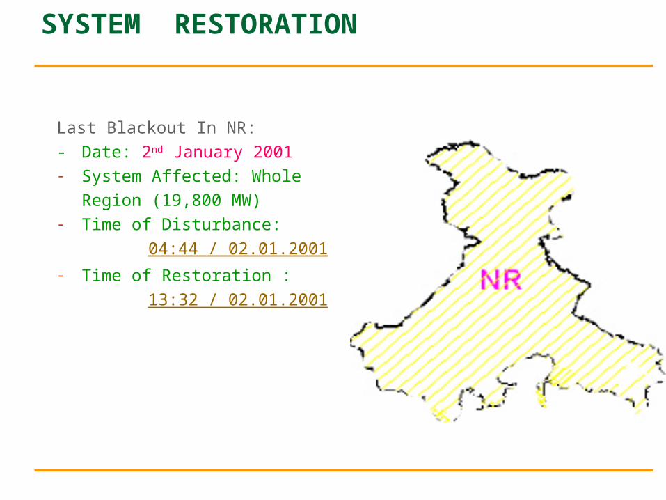
Last Blackout In NR:
- Date: 2nd January 2001- System Affected: Whole
Region (19,800 MW)- Time of Disturbance:
04:44 / 02.01.2001- Time of Restoration :
13:32 / 02.01.2001
Defence Plan
Element Protection Line Protection Generator Protection Transformer Protection
Relays to prevent cascade tripping UFR dF/ dT Under Voltage
Islanding System Islanding Power Station Islanding
System Protection Schemes
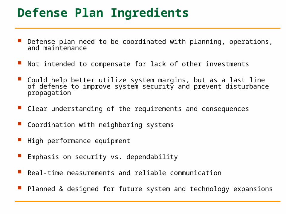
Defense Plan Ingredients
Defense plan need to be coordinated with planning, operations, and maintenance
Not intended to compensate for lack of other investments
Could help better utilize system margins, but as a last line of defense to improve system security and prevent disturbance propagation
Clear understanding of the requirements and consequences
Coordination with neighboring systems
High performance equipment
Emphasis on security vs. dependability
Real-time measurements and reliable communication
Planned & designed for future system and technology expansions
Restoration Planning
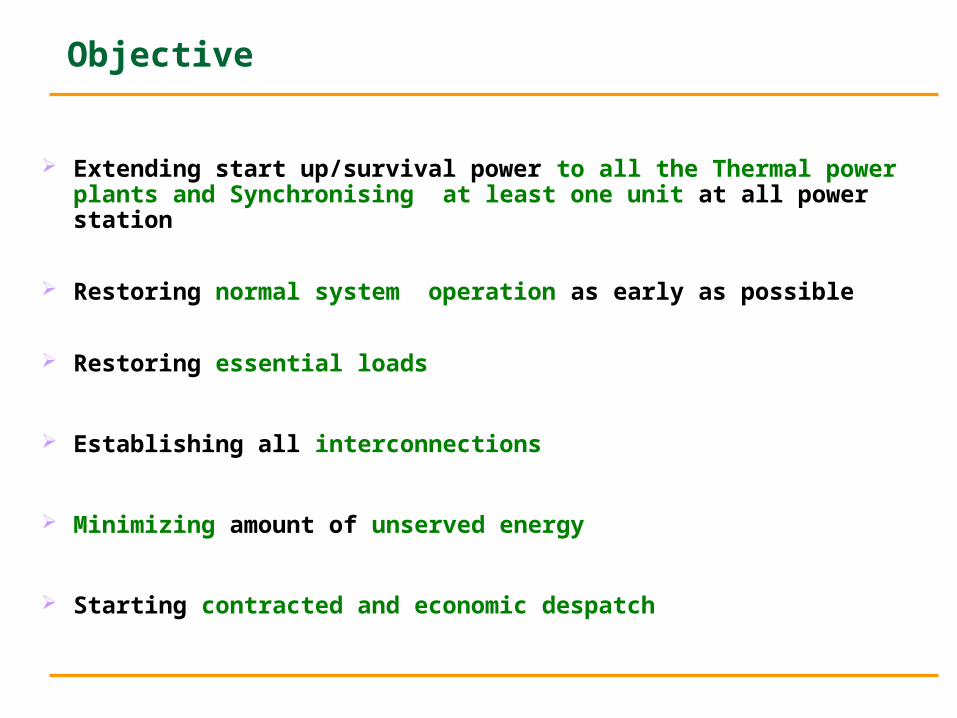
Objective
Extending start up/survival power to all the Thermal power plants and Synchronising at least one unit at all power station
Restoring normal system operation as early as possible
Restoring essential loads
Establishing all interconnections
Minimizing amount of unserved energy
Starting contracted and economic despatch
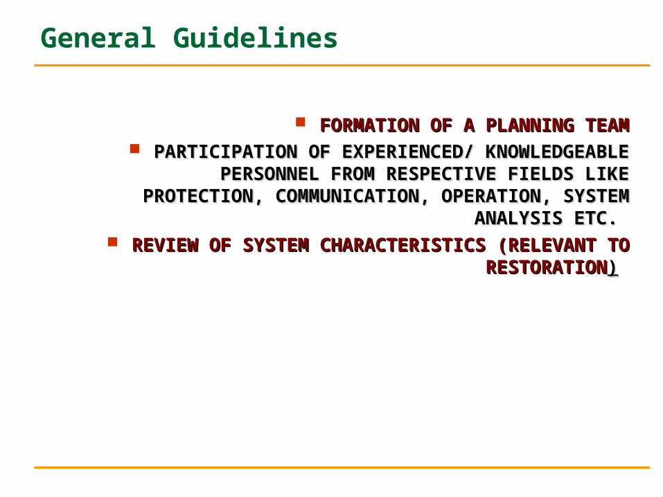
General Guidelines
FORMATION OF A PLANNING TEAMFORMATION OF A PLANNING TEAM PARTICIPATION OF EXPERIENCED/ KNOWLEDGEABLE PERSONNEL PARTICIPATION OF EXPERIENCED/ KNOWLEDGEABLE PERSONNEL
FROM RESPECTIVE FIELDS LIKE PROTECTION, COMMUNICATION, FROM RESPECTIVE FIELDS LIKE PROTECTION, COMMUNICATION, OPERATION, SYSTEM ANALYSIS ETC. OPERATION, SYSTEM ANALYSIS ETC.
REVIEW OF SYSTEM CHARACTERISTICS (RELEVANT TO REVIEW OF SYSTEM CHARACTERISTICS (RELEVANT TO RESTORATIONRESTORATION))
Problems /Constraints
Impaired communications, limited information.
Non-availability of SCADA/EMS application system.
Unfamiliarity with the situation (does not occur regularly)
Non availability /breakdown of a critical element
Time constraints re-assembling tie elements of power system.
Common Concerns
Time consuming nature of switching operation
Start-up timings of thermal units
Voltage problems during energisation of underloaded lines
Cold load inrush, power factors and coincident demand factors
Behaviour of protection system
System Characteristics
Structural
System size Metropolitan or rural
Nature of generation distribution and its mix Transmission voltage levels
Types and sizes of load blocks Availability of Interconnection Assistance
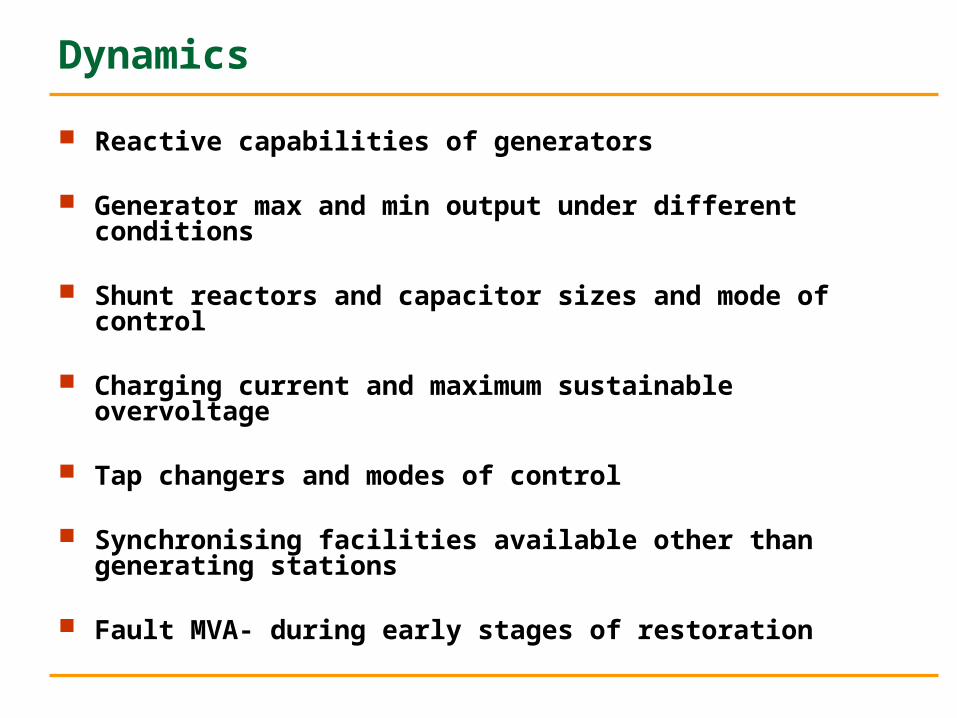
Dynamics
Reactive capabilities of generators
Generator max and min output under different conditions
Shunt reactors and capacitor sizes and mode of control
Charging current and maximum sustainable overvoltage
Tap changers and modes of control
Synchronising facilities available other than generating stations
Fault MVA- during early stages of restoration
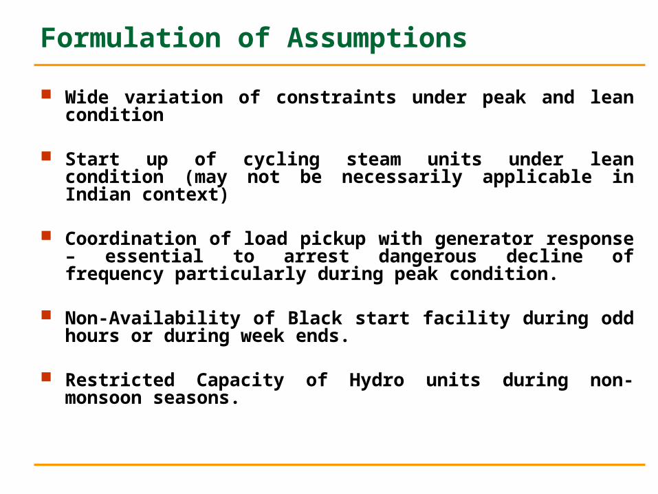
Formulation of Assumptions
Wide variation of constraints under peak and lean condition
Start up of cycling steam units under lean condition (may not be necessarily applicable in Indian context)
Coordination of load pickup with generator response – essential to arrest dangerous decline of frequency particularly during peak condition.
Non-Availability of Black start facility during odd hours or during week ends.
Restricted Capacity of Hydro units during non-monsoon seasons.
Strategies and Tactics
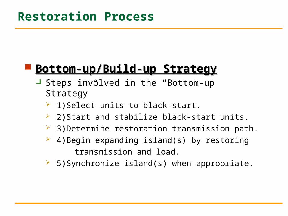
Restoration Process
Bottom-up/Build-up StrategyBottom-up/Build-up Strategy Steps involved in the “Bottom-up Strategy”
1)Select units to black-start. 2)Start and stabilize black-start units. 3)Determine restoration transmission path. 4)Begin expanding island(s) by restoring
transmission and load. 5)Synchronize island(s) when appropriate.

Restoration Process
Restore backbone transmission system, usually from outside assistance.
Restore critical generating station and substation load from transmission system.
Bring on more generation. Restore underlying transmission system. Continue restoring load.
Top-down / Build down strategyTop-down / Build down strategy
Combination Approach
Combines the “Build-up” and “Build-down” approach.
Steps in this approach include: Restoring transmission from an outside source at the
same time as building “islands” of generation. Interconnecting “islands” with each other or outside
source when able.
Selection of Restoration Strategy
Restoration method chosen depends on: Extent of blackout Availability of outside assistance Availability of internal black-start generation Objectives of restoration Utility philosophy/procedure
Restoration Tasks
Restoration Tasks
INITIAL ASSESSMENT SYSTEM STATUS DETERMINATION PLANT PREPARATION SERVICES/START-UP NETWORK PREPARATION NETWORK ENERGISATION LOAD RESTORATION SYSTEM REBUILDING
Initial Assessment
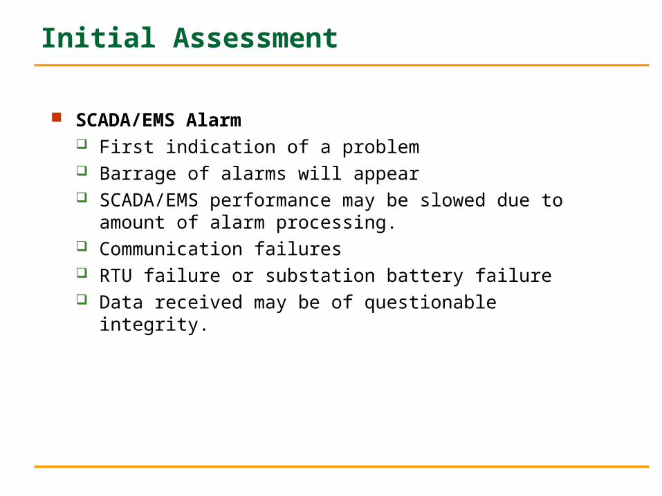
SCADA/EMS Alarm First indication of a problem Barrage of alarms will appear SCADA/EMS performance may be slowed due to amount of
alarm processing. Communication failures RTU failure or substation battery failure Data received may be of questionable integrity.
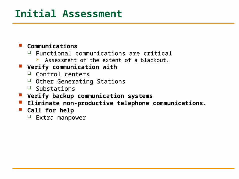
Communications Functional communications are critical
Assessment of the extent of a blackout. Verify communication with
Control centers Other Generating Stations Substations
Verify backup communication systems Eliminate non-productive telephone communications. Call for help
Extra manpower
Initial Assessment
System Status Determination
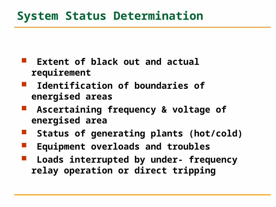
Extent of black out and actual requirement Identification of boundaries of energised areas Ascertaining frequency & voltage of energised area Status of generating plants (hot/cold) Equipment overloads and troubles Loads interrupted by under- frequency relay operation or
direct tripping
Determining Generator Status
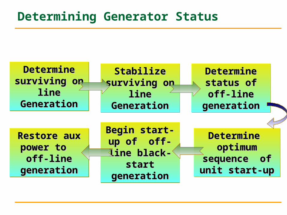
Determine Determine surviving on line surviving on line
GenerationGeneration
Determine Determine surviving on line surviving on line
GenerationGeneration
Stabilize Stabilize surviving on line surviving on line
GenerationGeneration
Stabilize Stabilize surviving on line surviving on line
GenerationGeneration
Determine status Determine status of off-line of off-line generationgeneration
Determine status Determine status of off-line of off-line generationgeneration
Restore aux Restore aux power to off-line power to off-line
generationgeneration
Restore aux Restore aux power to off-line power to off-line
generationgeneration
Begin start-up of Begin start-up of off-line black-off-line black-
start generationstart generation
Begin start-up of Begin start-up of off-line black-off-line black-
start generationstart generation
Determine Determine optimum sequence optimum sequence
of unit start-upof unit start-up
Determine Determine optimum sequence optimum sequence
of unit start-upof unit start-up
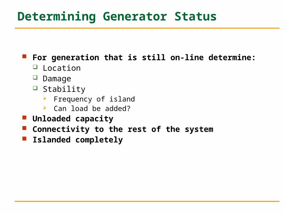
For generation that is still on-line determine: Location Damage Stability
Frequency of island Can load be added?
Unloaded capacity Connectivity to the rest of the system Islanded completely
Determining Generator Status
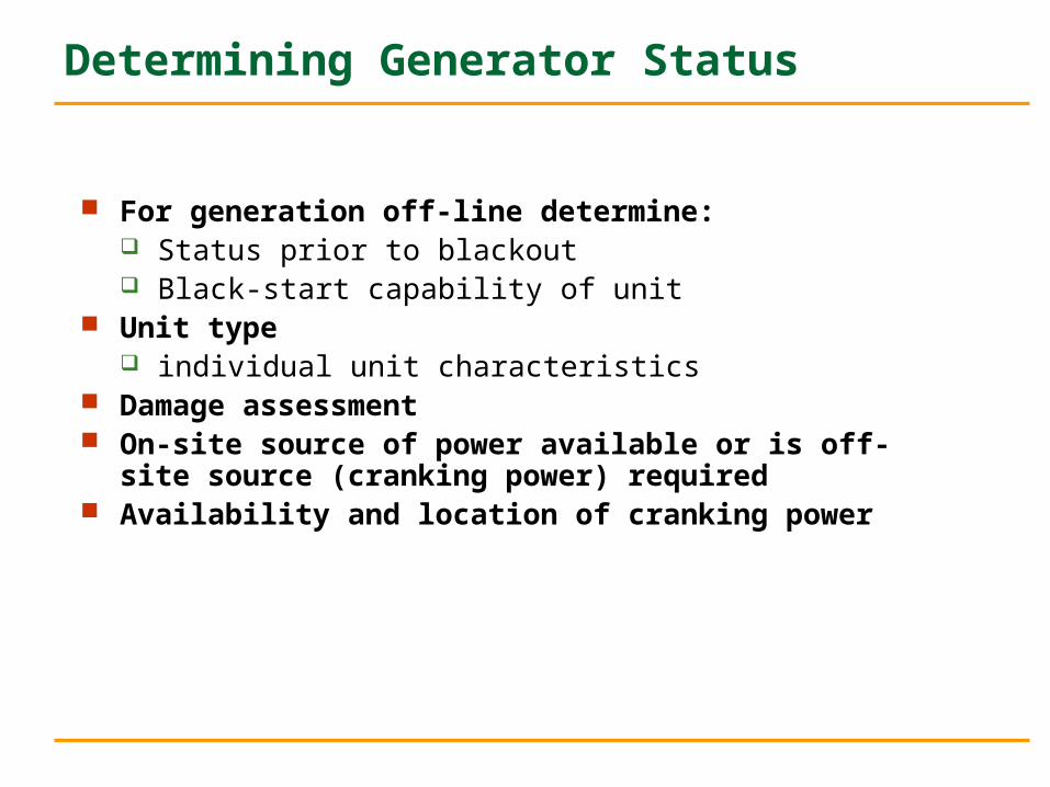
For generation off-line determine: Status prior to blackout Black-start capability of unit
Unit type individual unit characteristics
Damage assessment On-site source of power available or is off-site source
(cranking power) required Availability and location of cranking power
Determining Generator Status
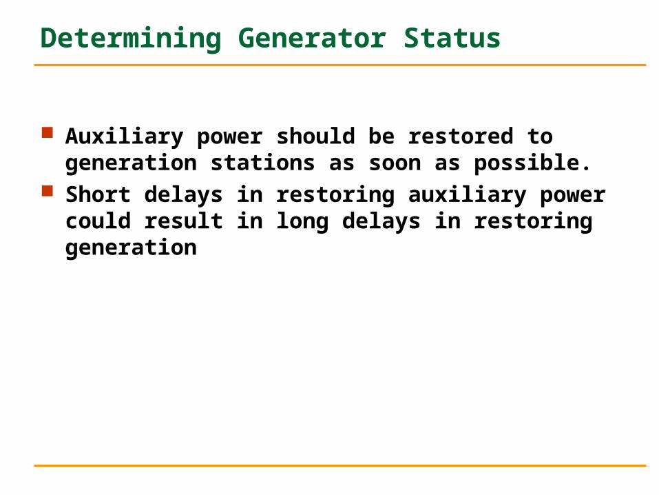
Auxiliary power should be restored to generation stations as soon as possible.
Short delays in restoring auxiliary power could result in long delays in restoring generation
Determining Generator Status
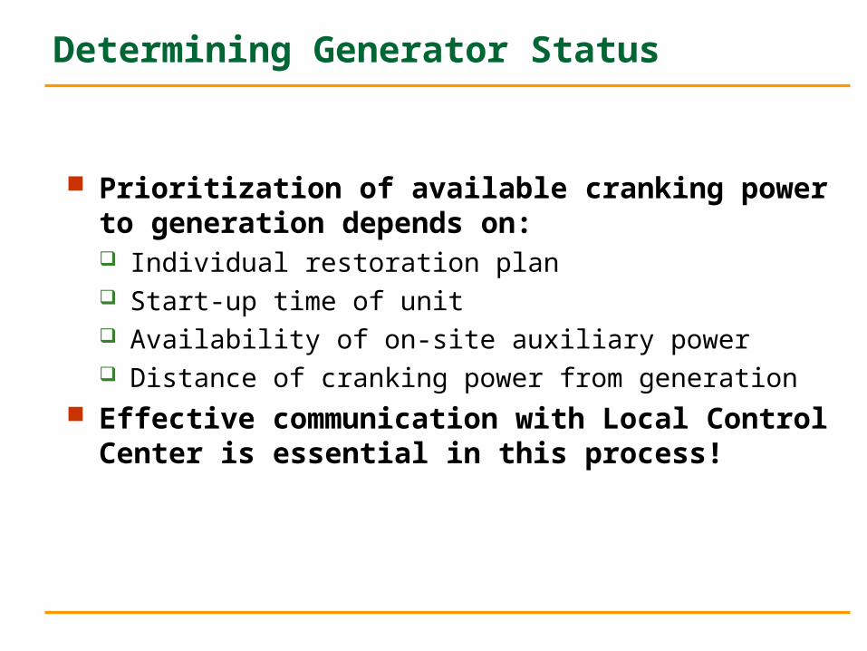
Prioritization of available cranking power to generation depends on: Individual restoration plan Start-up time of unit Availability of on-site auxiliary power Distance of cranking power from generation
Effective communication with Local Control Center is essential in this process!
Determining Generator Status
Generating plant operators take actions to perform a safe plant shutdown.
Steam plant operators implement start-up procedures immediately following a plant shutdown unless instructed otherwise by the dispatcher.
Governors must be in service. Plant operators must take action on their own
To control frequency outside the range of 49-50.5 Hz To maintain coordination with appropriate load despatch
centre under control
Determining Generator Status
Network Preparation Clearing all de-energised buses Global opening of all the breakers Sectionalising a system into sub-systems to enable parallel
restoration of islands Under frequency relays may have to be kept out of service at the
initial stage Making provision of cranking power for generating units Immediate resumption of power supply to the pumps meant for
high pressure cable
Reactive Power Balance
Energising EHV circuits or High voltage cable to be avoided as far as possible
Shunt reactor at the far end of the cable/EHV O/H line being energised to be taken into service first
Radial load to be put first Global knowledge about the magnitude and location of
reactive reserves of the system
Load Restoration
Priority load for restoration Generating Unit auxiliary power Nuclear Station auxiliary power
Substation light and power Traction Supplies Supply to Collieries Natural gas or oil supply facilities
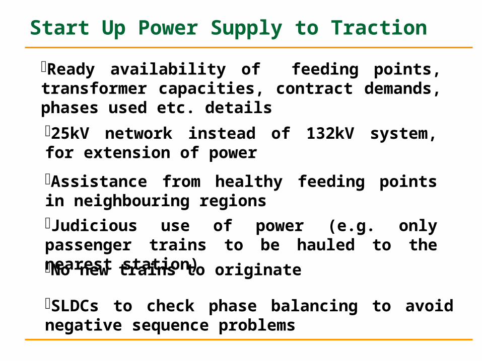
Ready availability of feeding points, transformer capacities, contract demands, phases used etc. details
25kV network instead of 132kV system, for extension of power
Assistance from healthy feeding points in neighbouring regionsJudicious use of power (e.g. only passenger trains to be hauled to the nearest station)No new trains to originate
SLDCs to check phase balancing to avoid negative sequence problems
Start Up Power Supply to Traction
Load Restoration
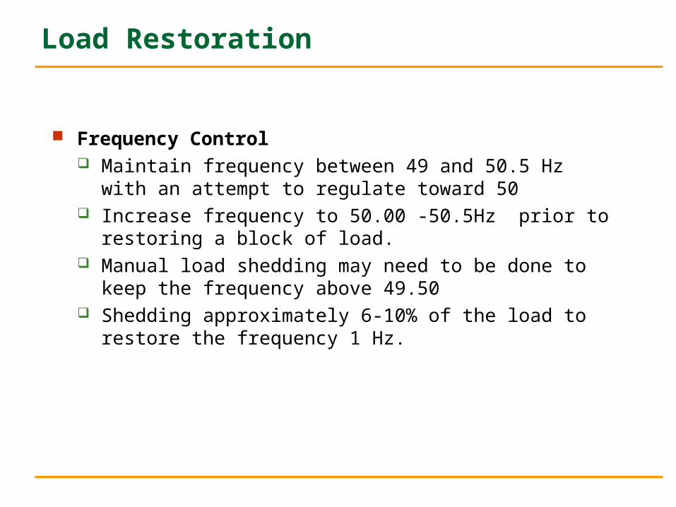
Frequency Control Maintain frequency between 49 and 50.5 Hz with an attempt
to regulate toward 50 Increase frequency to 50.00 -50.5Hz prior to restoring a
block of load. Manual load shedding may need to be done to keep the
frequency above 49.50 Shedding approximately 6-10% of the load to restore the
frequency 1 Hz.
Load Restoration
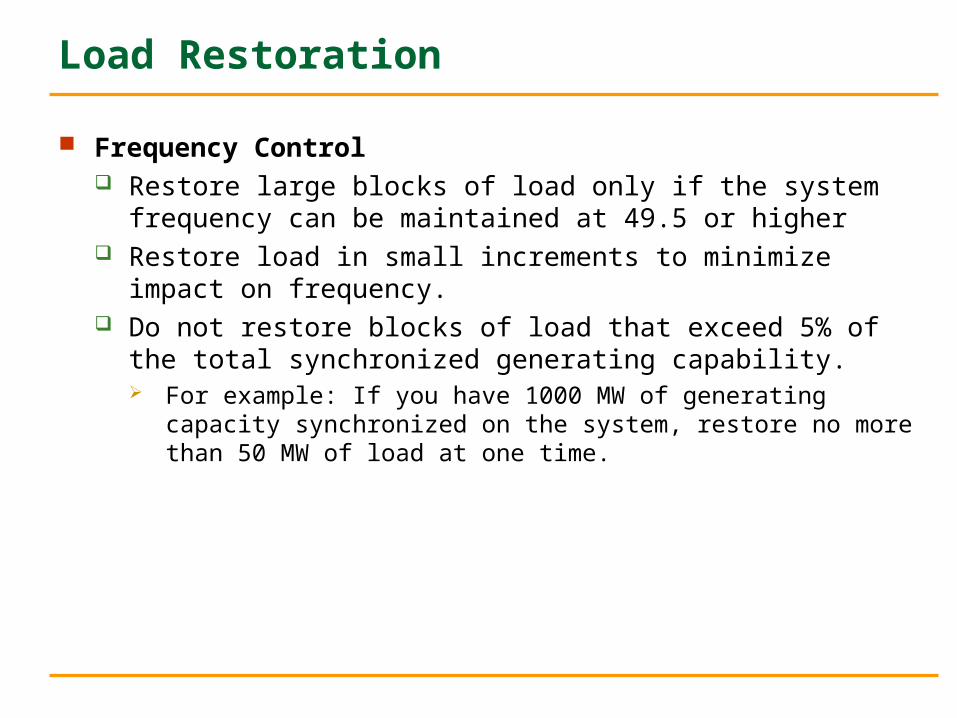
Frequency Control Restore large blocks of load only if the system frequency can be
maintained at 49.5 or higher Restore load in small increments to minimize impact on frequency. Do not restore blocks of load that exceed 5% of the total
synchronized generating capability. For example: If you have 1000 MW of generating capacity
synchronized on the system, restore no more than 50 MW of load at one time.
Island Interconnection
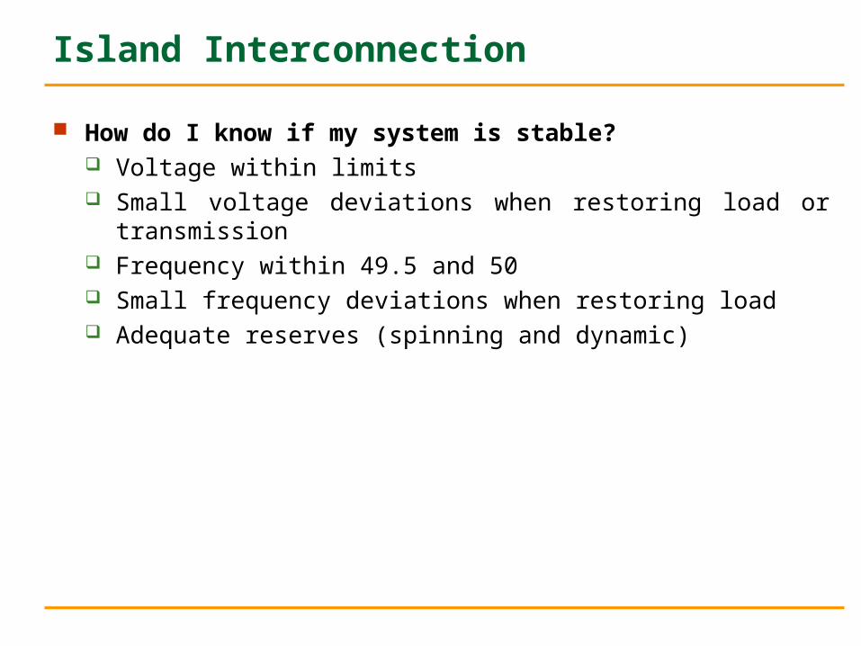
How do I know if my system is stable? Voltage within limits Small voltage deviations when restoring load or transmission Frequency within 49.5 and 50 Small frequency deviations when restoring load Adequate reserves (spinning and dynamic)
Synchronisation Frequency and voltage of the smaller island should be adjusted to match the frequency and
voltage of larger island Frequency and voltage in a smaller system are able to be moved more easily with smaller generation
shifts. Failure to match frequency and voltage between the two areas can result in significant equipment
damage and possible shut-down of one or both areas.
Post-synchronism If possible, close any other available tie-lines between the two newly connected systems to
strengthen stability Larger company has more resources to control frequency The larger Utility/Area will control frequency while the other will resort to tie-line control through
appropriate demand/generation management.
Island Interconnection
Island Interconnection
Benefits of Island Interconnection Provides a more stable combined system.
More system inertia Enables quicker load pickup
Allows for sharing of reserves Each area now only required to approximately carry 1/2
as much reserve. Allows for supply of energy for load among connected
areas. Additional control and regulation of Generation Further opportunity to connect another island
•Close and continual co-ordination among power system,
power plant and field operators
•Neighbouring utilities, local governmental authorities to be
informed time to time about the progress of
restoration.
•To depend more on the utilities own communication facilities
Logistics and communication
•Commando group to be formed as the system
complexity grows.
•Group should consist of engineers from different fields
and belonging to different utilities.
•Perfect understanding in this core group
•It enchances the moral strength of field officers as well as
reduces restoration time
Expert / Commando Group
A TECHNICAL PERSON OUTSIDE TIHE RESTORATION
TEAM SHOULD AUDIT THE ACTIVITIES.
AUDITED RESTORATION PLAN MUST BE UPDATED.
DOCUMENTS MUST BE REVISED REGULARLY TO REFLECT THE LATEST CHARACTERISTICS OF THE SYSTEM.
CHANGES IN THE SCADA/EMS INSTALLATION OR MAJOR PLANT CONTROL, AVAILABLE TOOLS ALSO TO BE INCORPORATED.
AUDITS AND UPDATES
INSTRUCTION MANUALS OR AUDIO –VISUAL TAPES, FOR
INDEPENDENT STUDY
CLASSROOM INSTRUCTIONS
LEARNING FROM PAST EXPERIENCE DURING RESTORATION.
OPERATOR TRAINING ON SIMULATOR.
ROLE PLAY
OPERATOR’ S PROBLEM SOLVING
CAPABILITY COULD ALSO BE, EXPLORED AND DEVELOPED.
ALTERNATIVE SOURCE OF FINDING NEW IDEAS.
DETAILED INTERACTION WITH THE PERSONS INVOLVED IN
RESTORATION
TRAINING
DOCUMENTATION
PURPOSE: TRAINING, REFERENCE, IMPROVEMENT OF
RESTORATION PROCEDURES.
SHOULD BE READILY ACCESSIBLE AND EASILY
UNDERSTOOD.
SHOULD BE STORED IN A CONVENIENT MEDIA FOR
QUICK PROCESSING.
SHOULD BE ILLUSTRATED WITH FAMILIAR DIAGRAMS
AND CHARTS
ACTIONS REJECTED AND INCORPORATED IN THE
PLAN MUST BE RECORDED
Experience
UFR actuated Automatic Load shedding was not fully
implemented
Inadequate communication and telemetering arrangement
reduced the logistic to load despatchers
Communication & Co-ordination problem
Laid down procedure of restoration was not readily available
to all
Procedure needs to be reviewed periodically in view of
changing configuration of the system
Few Useful Data/Thumb rules
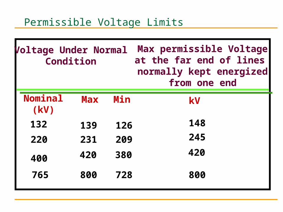
Permissible Voltage Limits
Voltage Under NormalCondition
Max permissible Voltageat the far end of lines
normally kept energizedfrom one end
Nominal(kV)
Max Min kV
132 139 126 148
220
400
765
231
420
800
209
380
728
245
420
800
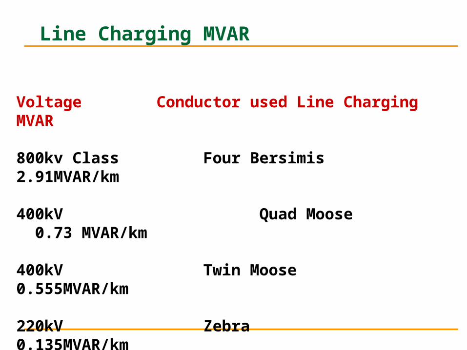
Line Charging MVAR
Voltage Conductor used Line Charging MVAR
800kv Class Four Bersimis 2.91MVAR/km
400kV Quad Moose 0.73 MVAR/km
400kV Twin Moose 0.555MVAR/km
220kV Zebra 0.135MVAR/km
132kV Panther: 0. 05 MVAR/km
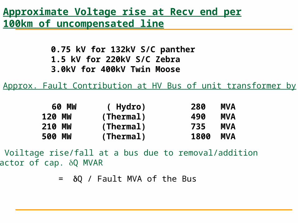
Approximate Voltage rise at Recv end per 100km of uncompensated line
0.75 kV for 132kV S/C panther1.5 kV for 220kV S/C Zebra3.0kV for 400kV Twin Moose
Approx. Fault Contribution at HV Bus of unit transformer by
60 MW ( Hydro) 280 MVA120 MW (Thermal) 490 MVA210 MW (Thermal) 735 MVA500 MW (Thermal) 1800 MVA
Approx. Voiltage rise/fall at a bus due to removal/addition of a reactor of cap. Q MVAR
= Q / Fault MVA of the Bus
Paradigm Shift
Normal Mode of OperationNormal Mode of Operation
Maintain Status quo
Peace time Operation
RestorationRestoration
Challenging –Change Status quo
War time Operation