Embed Size (px)
Citation preview
REVISION CONTROL SHEET
DOCUMENT TYPE: TECHNICAL SPECIFICATION
NO: PP-E-2536 Rev.No. R0
TECHNICAL SPECIFICATIONFOR
UPGRADATION OF DISTURBANCE RECODER SYSTEM
Rev. No.& Date
Descriptionof revision
Revised byName &Signature
Checked byName &Signature
Reviewed byName &Signature
Approvedby Name &Signature
NPCIL PROPRITORY
This document is the property of Nuclear Power
Corporation of India Limited. No exploitation or transfer of
any information contained herein is permitted in the
absence of an agreement with NPCIL and neither the
document nor any such information may be released
without the written consent of NPCIL
NUCLEAR POWER CORPORATION OF INDIA LTD.220MWe ATOMIC POWER PROJECTTECHNICAL SPECIFICATION FOR
UPGRADATION OF DISTURBANCE RECORDER SYSTEM
Page 4 of 52Rev. No. R0
SPECIFICATION NO.: PP-E-2536NOT FOR PUBLICATION / PRESENTATION OUTSIDE NPCIL
AUGUST, 2015
1.0 SCOPE OF SUPPLY / WORKS / SERVICES.
1.1 This specification covers the design, engineering, software deployment/customization,material, constructional features, manufacture, inspection and testing at theCONTRACTOR's/his SUB-CONTRACTOR's works, packing, transportation anddelivery at site, erection, performance testing at site and commissioning of ElectricalDisturbance Recorder for Kaiga Atomic Power Stations-3&4.
1.2 It is not the intent to specify completely herein, all details of design and construction ofthe equipment. However, the equipment shall conform in all respects to high standardsof engineering, design and workmanship and be capable of performing continuouscommercial operation up to the CONTRACTOR'S guarantees in a manner acceptableto the PURCHASER, who will interpret the meaning of drawings and specificationsand shall be entitled to reject any work or material which, in his judgement, is not infull accordance therewith.
1.3 The scope includes but not limited to the following items / services described hereinand elsewhere in the tender package.
1.3.1 Retrofitting of existing disturbance recorders (DRs) of M/s Alstom make Micom M840for recording and display of desired system's analog and digital parameters prior to,during and after system disturbances for duration specified in subsequent sections. Thisincludes supply of required DR modules with all sub system modules.
1.3.2 A common evaluation unit with necessary hardware and software shall be supplied formonitoring, diagnosis of DR modules and for downloading and report generation/printing of recorded disturbance data from DR modules.
1.3.3 Replacing existing DR units with DR units under supply. Inter connection and termination withexternal cables.
1.3.4 Internal wiring, inter-cabinet wiring, connections between the DR untis and toperipherals with proper cable glanding and termination.
1.3.5 Fiber optic cables required for data communication, time synchronization and crosstriggering between various DRs and evaluation.
1.3.6 Erection, testing and commissioning of components in the existing panels at site.
1.3.7 Mounting tables for DR evaluation unit and printer
1.3.8 Spares as indicated in clause 4.1 of this specification shall be supplied by theCONTRACTOR
1.3.9 Maintenance tools and tackles as described in clause 10 of this specification shall besupplied by the CONTRACTOR.
NUCLEAR POWER CORPORATION OF INDIA LTD.220MWe ATOMIC POWER PROJECTTECHNICAL SPECIFICATION FOR
UPGRADATION OF DISTURBANCE RECORDER SYSTEM
Page 5 of 52Rev. No. R0
SPECIFICATION NO.: PP-E-2536NOT FOR PUBLICATION / PRESENTATION OUTSIDE NPCIL
AUGUST, 2015
1.4 Training of PURCHASER's personnel at manufacturer's works on various design,testing and maintenance aspects and also at PURCHASER's site on installation,maintenance, carrying out adjustments etc.
1.5 Whether called for specifically or not, all accessories required for normal operation ofequipment are deemed to be considered as a part of the CONTRACTOR'S scope ofsupply.
1.6 The available drawings for the existing system where required would be furnished tothe successful CONTRACTOR for detailed engineering. In case of non-availability ofdrawings/details it shall be the CONTRACTOR’s responsibility to get the informationfrom available sources
1.7 On award of PO, CONTRACTOR shall furnish the schematics, general arrangementdrawings, panel wiring diagrams etc for Purchaser’s approval.
1.8 The CONTRACTOR shall submit commissioning procedure and drawings afterplacement of order. Among other details this procedure shall also contain detailedrequirement for handling, checklist for assembly and erection, special instructions,precautions erection drawings, log sheets etc
NUCLEAR POWER CORPORATION OF INDIA LTD.220MWe ATOMIC POWER PROJECTTECHNICAL SPECIFICATION FOR
UPGRADATION OF DISTURBANCE RECORDER SYSTEM
Page 6 of 52Rev. No. R0
SPECIFICATION NO.: PP-E-2536NOT FOR PUBLICATION / PRESENTATION OUTSIDE NPCIL
AUGUST, 2015
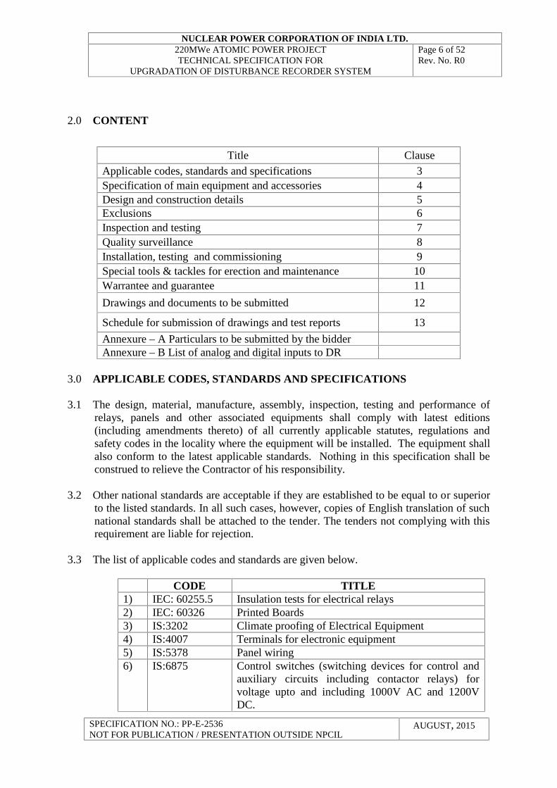
2.0 CONTENT
3.0 APPLICABLE CODES, STANDARDS AND SPECIFICATIONS
3.1 The design, material, manufacture, assembly, inspection, testing and performance ofrelays, panels and other associated equipments shall comply with latest editions(including amendments thereto) of all currently applicable statutes, regulations andsafety codes in the locality where the equipment will be installed. The equipment shallalso conform to the latest applicable standards. Nothing in this specification shall beconstrued to relieve the Contractor of his responsibility.
3.2 Other national standards are acceptable if they are established to be equal to or superiorto the listed standards. In all such cases, however, copies of English translation of suchnational standards shall be attached to the tender. The tenders not complying with thisrequirement are liable for rejection.
3.3 The list of applicable codes and standards are given below.
CODE TITLE1) IEC: 60255.5 Insulation tests for electrical relays2) IEC: 60326 Printed Boards3) IS:3202 Climate proofing of Electrical Equipment4) IS:4007 Terminals for electronic equipment5) IS:5378 Panel wiring6) IS:6875 Control switches (switching devices for control and
auxiliary circuits including contactor relays) forvoltage upto and including 1000V AC and 1200VDC.
Title ClauseApplicable codes, standards and specifications 3Specification of main equipment and accessories 4Design and construction details 5Exclusions 6Inspection and testing 7Quality surveillance 8Installation, testing and commissioning 9Special tools & tackles for erection and maintenance 10Warrantee and guarantee 11
Drawings and documents to be submitted 12
Schedule for submission of drawings and test reports 13
Annexure – A Particulars to be submitted by the bidderAnnexure – B List of analog and digital inputs to DR
NUCLEAR POWER CORPORATION OF INDIA LTD.220MWe ATOMIC POWER PROJECTTECHNICAL SPECIFICATION FOR
UPGRADATION OF DISTURBANCE RECORDER SYSTEM
Page 7 of 52Rev. No. R0
SPECIFICATION NO.: PP-E-2536NOT FOR PUBLICATION / PRESENTATION OUTSIDE NPCIL
AUGUST, 2015
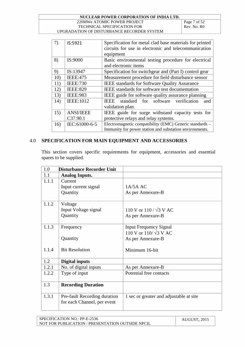
7) IS:5921 Specification for metal clad base materials for printedcircuits for use in electronic and telecommunicationequipment
8) IS:9000 Basic environmental testing procedure for electricaland electronic items
9) IS:13947 Specification for switchgear and (Part I) control gear10) IEEE:475 Measurement procedure for field disturbance sensor11) IEEE:730 IEEE standards for Software Quality Assurance12) IEEE:829 IEEE standards for software test documentation13) IEEE:983 IEEE guide for software quality assurance planning14) IEEE:1012 IEEE standard for software verification and
validation plan.15) ANSI/IEEE
C37.90.1IEEE guide for surge withstand capacity tests forprotective relays and relay systems.
16) IEC:61000-6-5 Electromagnetic compatibility (EMC) Generic standards –Immunity for power station and substation environments.
4.0 SPECIFICATION FOR MAIN EQUIPMENT AND ACCESSORIES
This section covers specific requirements for equipment, accessories and essentialspares to be supplied.
1.0 Disturbance Recorder Unit1.1 Analog Inputs.1.1.1 Current
Input current signalQuantity
1A/5A ACAs per Annexure-B
1.1.2 VoltageInput Voltage signalQuantity
110 V or 110 / 3 V ACAs per Annexure-B
1.1.3
1.1.4
Frequency
Quantity
Bit Resolution
Input Frequency Signal110 V or 110/ 3 V ACAs per Annexure-B
Minimum 16-bit
1.2 Digital inputs1.2.1 No. of digital inputs As per Annexure-B1.2.2 Type of input Potential free contacts
1.3 Recording Duration
1.3.1 Pre-fault Recording durationfor each Channel, per event
1 sec or greater and adjustable at site
NUCLEAR POWER CORPORATION OF INDIA LTD.220MWe ATOMIC POWER PROJECTTECHNICAL SPECIFICATION FOR
UPGRADATION OF DISTURBANCE RECORDER SYSTEM
Page 8 of 52Rev. No. R0
SPECIFICATION NO.: PP-E-2536NOT FOR PUBLICATION / PRESENTATION OUTSIDE NPCIL
AUGUST, 2015
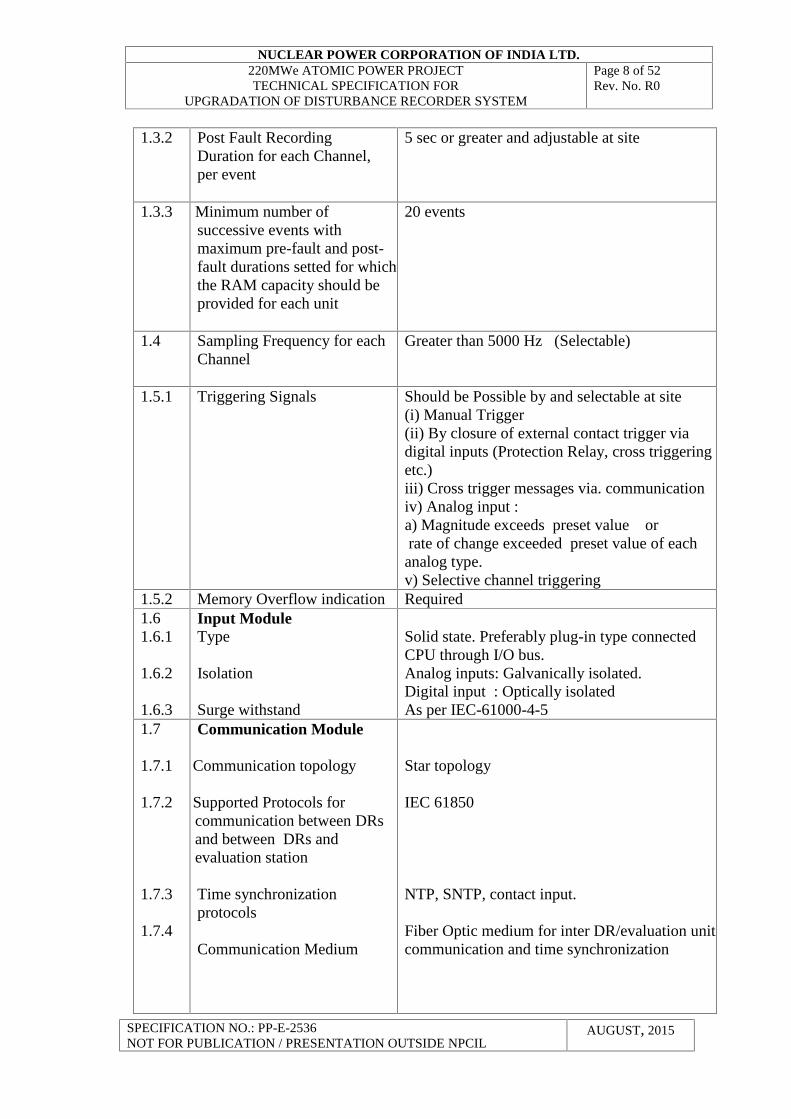
1.3.2 Post Fault RecordingDuration for each Channel,per event
5 sec or greater and adjustable at site
1.3.3 Minimum number ofsuccessive events withmaximum pre-fault and post-fault durations setted for whichthe RAM capacity should beprovided for each unit
20 events
1.4 Sampling Frequency for eachChannel
Greater than 5000 Hz (Selectable)
1.5.1 Triggering Signals Should be Possible by and selectable at site(i) Manual Trigger(ii) By closure of external contact trigger viadigital inputs (Protection Relay, cross triggeringetc.)iii) Cross trigger messages via. communicationiv) Analog input :a) Magnitude exceeds preset value orrate of change exceeded preset value of eachanalog type.v) Selective channel triggering
1.5.2 Memory Overflow indication Required1.61.6.1
1.6.2
1.6.3
Input ModuleType
Isolation
Surge withstand
Solid state. Preferably plug-in type connectedCPU through I/O bus.Analog inputs: Galvanically isolated.Digital input : Optically isolatedAs per IEC-61000-4-5
1.7
1.7.1
1.7.2
1.7.3
1.7.4
Communication Module
Communication topology
Supported Protocols forcommunication between DRsand between DRs andevaluation station
Time synchronizationprotocols
Communication Medium
Star topology
IEC 61850
NTP, SNTP, contact input.
Fiber Optic medium for inter DR/evaluation unitcommunication and time synchronization
sig
NUCLEAR POWER CORPORATION OF INDIA LTD.220MWe ATOMIC POWER PROJECTTECHNICAL SPECIFICATION FOR
UPGRADATION OF DISTURBANCE RECORDER SYSTEM
Page 9 of 52Rev. No. R0
SPECIFICATION NO.: PP-E-2536NOT FOR PUBLICATION / PRESENTATION OUTSIDE NPCIL
AUGUST, 2015
nals.
2.02.1
2.1.1
2.1.2
2.1.3
2.1.4
2.1.5
2.1.6
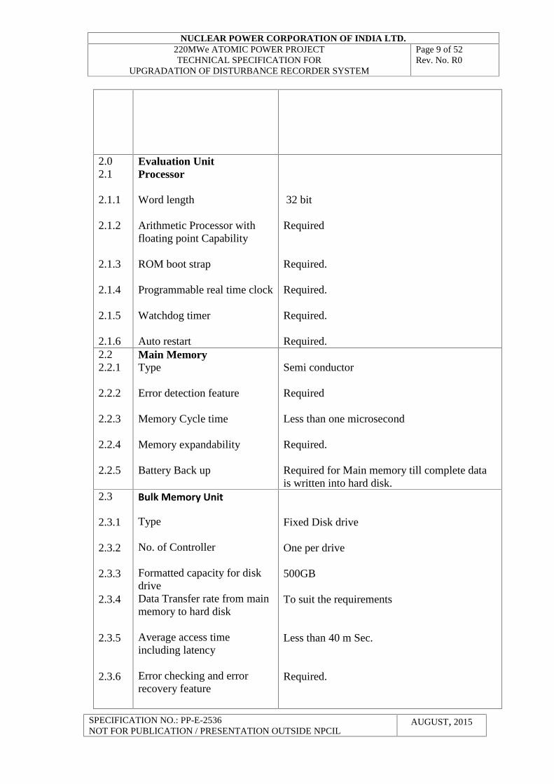
Evaluation UnitProcessor
Word length
Arithmetic Processor withfloating point Capability
ROM boot strap
Programmable real time clock
Watchdog timer
Auto restart
32 bit
Required
Required.
Required.
Required.
Required.2.22.2.1
2.2.2
2.2.3
2.2.4
2.2.5
Main MemoryType
Error detection feature
Memory Cycle time
Memory expandability
Battery Back up
Semi conductor
Required
Less than one microsecond
Required.
Required for Main memory till complete datais written into hard disk.
2.3
2.3.1
2.3.2
2.3.3
2.3.4
2.3.5
2.3.6
Bulk Memory Unit
Type
No. of Controller
Formatted capacity for diskdriveData Transfer rate from mainmemory to hard disk
Average access timeincluding latency
Error checking and errorrecovery feature
Fixed Disk drive
One per drive
500GB
To suit the requirements
Less than 40 m Sec.
Required.
NUCLEAR POWER CORPORATION OF INDIA LTD.220MWe ATOMIC POWER PROJECTTECHNICAL SPECIFICATION FOR
UPGRADATION OF DISTURBANCE RECORDER SYSTEM
Page 10 of 52Rev. No. R0
SPECIFICATION NO.: PP-E-2536NOT FOR PUBLICATION / PRESENTATION OUTSIDE NPCIL
AUGUST, 2015
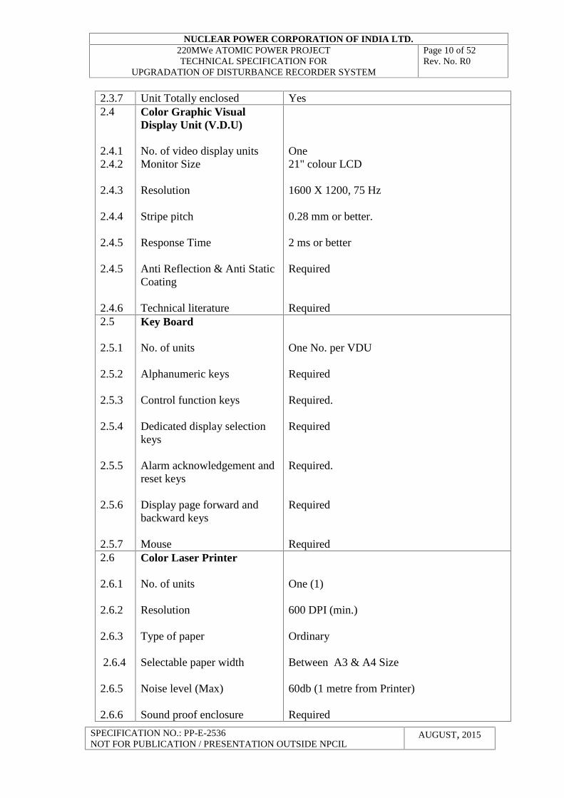
2.3.7 Unit Totally enclosed Yes2.4
2.4.12.4.2
2.4.3
2.4.4
2.4.5
2.4.5
2.4.6
Color Graphic VisualDisplay Unit (V.D.U)
No. of video display unitsMonitor Size
Resolution
Stripe pitch
Response Time
Anti Reflection & Anti StaticCoating
Technical literature
One21" colour LCD
1600 X 1200, 75 Hz
0.28 mm or better.
2 ms or better
Required
Required2.5
2.5.1
2.5.2
2.5.3
2.5.4
2.5.5
2.5.6
2.5.7
Key Board
No. of units
Alphanumeric keys
Control function keys
Dedicated display selectionkeys
Alarm acknowledgement andreset keys
Display page forward andbackward keys
Mouse
One No. per VDU
Required
Required.
Required
Required.
Required
Required2.6
2.6.1
2.6.2
2.6.3
2.6.4
2.6.5
2.6.6
Color Laser Printer
No. of units
Resolution
Type of paper
Selectable paper width
Noise level (Max)
Sound proof enclosure
One (1)
600 DPI (min.)
Ordinary
Between A3 & A4 Size
60db (1 metre from Printer)
Required
NUCLEAR POWER CORPORATION OF INDIA LTD.220MWe ATOMIC POWER PROJECTTECHNICAL SPECIFICATION FOR
UPGRADATION OF DISTURBANCE RECORDER SYSTEM
Page 11 of 52Rev. No. R0
SPECIFICATION NO.: PP-E-2536NOT FOR PUBLICATION / PRESENTATION OUTSIDE NPCIL
AUGUST, 2015
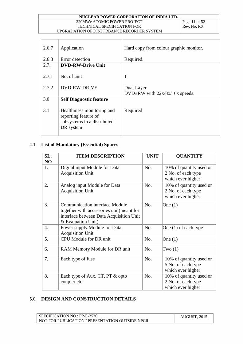
2.6.7
2.6.8
Application
Error detection
Hard copy from colour graphic monitor.
Required.2.7.
2.7.1
2.7.2
DVD-RW-Drive Unit
No. of unit
DVD-RW-DRIVE
1
Dual LayerDVD±RW with 22x/8x/16x speeds.
3.0
3.1
Self Diagnostic feature
Healthiness monitoring andreporting feature ofsubsystems in a distributedDR system
Required
4.1 List of Mandatory (Essential) Spares
SL.NO
ITEM DESCRIPTION UNIT QUANTITY
1. Digital input Module for DataAcquisition Unit
No. 10% of quantity used or2 No. of each typewhich ever higher
2. Analog input Module for DataAcquisition Unit
No. 10% of quantity used or2 No. of each typewhich ever higher
3. Communication interface Moduletogether with accessories unit(meant forinterface between Data Acquisition Unit& Evaluation Unit)
No. One (1)
4. Power supply Module for DataAcquisition Unit
No. One (1) of each type
5. CPU Module for DR unit No. One (1)
6. RAM Memory Module for DR unit No. Two (1)
7. Each type of fuse No. 10% of quantity used or5 No. of each typewhich ever higher
8. Each type of Aux. CT, PT & optocoupler etc
No. 10% of quantity used or2 No. of each typewhich ever higher
5.0 DESIGN AND CONSTRUCTION DETAILS
NUCLEAR POWER CORPORATION OF INDIA LTD.220MWe ATOMIC POWER PROJECTTECHNICAL SPECIFICATION FOR
UPGRADATION OF DISTURBANCE RECORDER SYSTEM
Page 12 of 52Rev. No. R0
SPECIFICATION NO.: PP-E-2536NOT FOR PUBLICATION / PRESENTATION OUTSIDE NPCIL
AUGUST, 2015
This Section covers the design, construction features performance and functionalrequirements of electrical disturbance recorder system.
5.1 Disturbance Recorder Modules/Units
5.1.1 Disturbance recorder system shall be of stand alone type with all input sub systemsmounted in a panel. Disturbance Recorder is provided to continuously monitor andrecord the analog inputs such as Voltage, Frequency and Current Waveforms along withrecording status of digital (contact) inputs from protection relays and Circuit Breakers, incase of occurrence of any system disturbances. The data made available by theDisturbance Recorder will be used for detailed analysis and study of cause and effect ofsuch disturbances and also to verify the performance of switchgear under disturbanceconditions. The duration for recording of pre fault and post fault conditions shall be asspecified under clause-4.
5.1.2 DR modules shall be mounted in disturbance recorder panel and located in switchyardcontrol room of switchyard control building.
5.1.3 DR evaluation unit shall be located in switchyard control room of switchyard controlbuilding.
5.1.4 Electrical disturbance recorder is provided for continuous monitoring, storing andrecording data during disturbances in 400 kV, 220 kV, 16.5kV, 6.6 kV systems and415V CL-II Power UPS bus.
5.1.5 The disturbance recorder shall be capable of accepting analog inputs from protectionCTs and PTs directly. The analog parameter measured will be line current, busvoltage and frequencies. The recorder shall also be capable of accepting digitalchannels through potential free contacts.
5.1.6 The system shall be suitable for real time operation. Required number of DR modulesshall be provided to cater to the total no. of disturbance inputs. All DR modules shallbe interconnected with each other and to the master evaluation station/unit throughsuitable communication links for centralized information.
5.1.7 The system shall be provided with clock facility to record the date and time of thedisturbance event. It shall be possible to set the clock manually or synchronize theequipment clock with GPS system. The clock shall record the date in terms of year,month and day and time in terms of hours, minutes, second and one thousandth ofsecond. System clock shall take care of leap year and months with differing no. ofdays on its own.
5.1.8 Adequate total storage capacity in Random Access solid state memory in each DRunit shall be available to store data of all analog and digital channels for at least last20 disturbances at maximum scan rates provided for each disturbance for eachchannel. It shall be possible to display or printout the same on demand. In nocondition, disturbance data shall be lost in subsystem before transfer to the hard diskin the Evaluation unit. The pre and post-triggered record duration shall be selectable.
NUCLEAR POWER CORPORATION OF INDIA LTD.220MWe ATOMIC POWER PROJECTTECHNICAL SPECIFICATION FOR
UPGRADATION OF DISTURBANCE RECORDER SYSTEM
Page 13 of 52Rev. No. R0
SPECIFICATION NO.: PP-E-2536NOT FOR PUBLICATION / PRESENTATION OUTSIDE NPCIL
AUGUST, 2015
5.1.9 DR unit should have the provision to continue with the transfer of recorded data to theevaluation unit even when new disturbances are being recorded.
5.1.10 The analog to digital converter shall be at least 16-bits resolution.
5.1.11 Each of the input Channels shall be scanned at minimum sampling rate of 5000samples/sec (selectable). Each individual channel shall be suitable for calibrationindependently. Each analog channel should have a potentiometer for set pointadjustment.
5.1.12 If the VENDOR uses interposing transformers to convert secondary outputs of CTsand PTs for measuring the absolute value during the disturbance, the vendor shallensure that distortion does not take place due to the saturation of these interposingtransformers during the disturbance. The vendor shall supply relevant calculation forthe knee point voltages selected for these transformers to take care of aboverequirements.
5.1.13 If any auxiliary CTs, opto coupler, isolating PTs are needed for receiving Analog /digital input, bidder shall include such PTs, CTs and opto coupler in supplier's scopeof supply.
5.1.14 The VENDOR shall ensure that the variations in currents and voltage amplitudes arerecorded without introduction of chopping or delays in the internal circuits ofdisturbance recorder, including interposing transformers.
5.1.15 The disturbance recorder shall be triggered when –a) Analog input or its rate of change exceeds preset value.b) Digital channel contact changeover condition takes place in specified manner (`NO' to
`NC' or vice versa).c) Any other DR units triggers (cross triggering)d) Manual triggering (push button).
5.1.16 The disturbance recorder shall have provision for manual external triggering facility fortesting the functioning of the system. Triggering shall cause all digital and analog inputsto be recorded. When triggering is based on analog values, provision should exist to guardagainst false triggering by switching transients/ lightning surges. Bidder shall indicate theprovisions made to take care of these aspects.
5.1.17 Defective digital/ analog input card should not cause triggering of the Systems.
5.1.18 Analog channel settings shall be field adjustable. Engineering functions like change oftrigger settings, skipping of any channel from scan, reconfiguration etc., shall bepassword / key lock protected.
5.1.19 The equipment shall be provided with self checking facility to check functioning of thevarious subsystems and to provide audio-visual alarm/indication on the operator consolein Data Acquisition panel and on the VDU in evaluation unit, in case of any fault in theequipment. It should be possible for operator to interrogate the system through operatingconsole in Data Acquisition panel to identify the defective module/defects. This should
NUCLEAR POWER CORPORATION OF INDIA LTD.220MWe ATOMIC POWER PROJECTTECHNICAL SPECIFICATION FOR
UPGRADATION OF DISTURBANCE RECORDER SYSTEM
Page 14 of 52Rev. No. R0
SPECIFICATION NO.: PP-E-2536NOT FOR PUBLICATION / PRESENTATION OUTSIDE NPCIL
AUGUST, 2015
cover memory overflow and loss of clock synchronism also. A potential free contact shallbe available for any trouble in disturbance recorder for PURCHASER'S SCADA system.
5.1.20 Potential free contacts for the following status/alarm indications shall be provided for thePurchasers use in SCADA/Control Panel:a) Readyb) Triggeredc) Power supply Faild) Buffer FullSimilarly LEDs/Indicating lamps, shall be provided In the acquisition unit for the above.
5.1.21 All the analog input to disturbance recorder shall be provided with galvanic isolation. Allthe digital input shall be provided with opto-coupler. Details of such provision shall beexplained in offer.
5.1.22 Disturbance recorder shall support IEC-61850 communication standard to communicatewith other data acquisition units.
5.1.23 Disturbance recorder system shall have self diagnostic feature which involves monitoringhealthiness of DR units, evaluation unit, network cables and switches etc. The monitoreddata shall be reported both locally and to evaluation unit both automatically and ondemand.
5.2 Evaluation Unit
5.2.1 The Evaluation Unit shall serve as the operator's work station and should be built aroundPersonal Computer with arithmetic Co-processor-bit CPU and necessary OperatingSystem. It shall be equipped with Hard Disk, Color Monitor, PC Mouse, DVD writerdrive and color laser printer.
5.2.2 Display monitor (Flat Panel Display)
The display monitor shall be an industry grade, field proven high-resolution monitor. Thefollowing design features shall be provided:
i) The character size, structure, color and brightness of the display shall be chosen so asto enable clear viewing in the maximum illumination levels in a switchyard controlroom without frequent adjustment/tuning.
ii) The display shall be stable, flicker-free, with good contrast, without distortion andghosting effect, without glare and reflection and with long life.
iii) The display monitor shall be of LED type and shall have high resolution (0.31 mm dotpitch, typically 1600 X 1200 on non-interlaced) color graphic capabilities.
iv) It shall have antiglare screen and shall have screen size of minimum 21" diagonal.v) It shall have other standard features, such as control for color, brightness, contrast,
vertical/horizontal shift, swivel type mounting etc
5.2.3 Key Board
The keyboard shall provide operator interface to the disturbance recorder in conjunctionwith CRT. The design features provided shall include but not limited to the following:
NUCLEAR POWER CORPORATION OF INDIA LTD.220MWe ATOMIC POWER PROJECTTECHNICAL SPECIFICATION FOR
UPGRADATION OF DISTURBANCE RECORDER SYSTEM
Page 15 of 52Rev. No. R0
SPECIFICATION NO.: PP-E-2536NOT FOR PUBLICATION / PRESENTATION OUTSIDE NPCIL
AUGUST, 2015
i) Alphanumeric Keys.ii) Key-lock switch control over critical system functions.iii) Page and cursor control keys.iv) Pre-defined function keys for various functions according to the type of keyboard.
5.2.4 Color laser Printer
Color inkjet/laser printer will be used for getting hard copies demanded from keyboards.This shall have following general features:
a) Designed for continuous trouble free operation with a minimum of maintenance.b) Quiet operation and suitable for location in switchyard control room.c) Easy maintainability, with provision for ease in execution of routine task such as
changing of ink cartridge, paper insertion etc.d) Control unit with all error detection, error reporting and fail-safe facilities.e) Off-line mode selector switch to enable safe maintenance.f) The hard copy of the records should be available on plain paper. No special paper
should be necessary.
5.2.5 DVD R&W Unit
DVD unit shall consist of a DVD drive with its controller. The controller shall bemicroprocessor based with following features.
a) Capacity for controlling one no. of DVD drive.b) Necessary local memory for required data buffer.c) Software required for DVD disk file managementd) Self test feature.
5.3 Software Requirements
5.3.1 The record of disturbance should be available from record on the request ofEngineer/Operator. The records of disturbance with different level of magnification shallbe possible. It should also be possible to copy the data in floppy disks to perform analysisat a later date. It shall be possible to obtain on CRT/Printer/Plotter the plot of any one ormore desired channels.
5.3.2 It should be possible to have record of disturbance in multi color with different channelsbeing represented by different colors. The choice of color should be in accordance withthe choice of Engineer.
5.3.3 A virus shield to prevent viruses from corrupting / destroying data file / programs shall beprovided.
5.3.4 The trace of waveform on paper should be related to the primary value of voltage/currenton the high voltage side. It should be possible to program transformation ratios ofCTs/PT/CVT in order that the scale factor relates the trace the amplitude to the primaryvalues.
5.3.5 The format of record should include the relevant information in clear text, enablingconfusion free analysis.
5.3.6 It shall be possible to get readout of the amplitude of any point on the waveform on CRTwith the cursor or mouse.
NUCLEAR POWER CORPORATION OF INDIA LTD.220MWe ATOMIC POWER PROJECTTECHNICAL SPECIFICATION FOR
UPGRADATION OF DISTURBANCE RECORDER SYSTEM
Page 16 of 52Rev. No. R0
SPECIFICATION NO.: PP-E-2536NOT FOR PUBLICATION / PRESENTATION OUTSIDE NPCIL
AUGUST, 2015
5.3.7 Facilities shall be provided to select following from menu:-
a) Grouping of channels for the purposes of display.b) Order of channel in record.c) Modification of scale along amplitude and time axis.d) Selection of channel colour.e) Selection of time segment of interest.
5.3.8 The software shall be capable of displaying instantaneous and RMS values of any givenanalog input.
5.3.9 Additionally, menu driven software shall calculate the fault location, i.e. distance to faultin K.M. based on the variation in the line parameters using instantaneous values of analoginputs that are available.
5.3.10 The computations should have accuracy better than 1%.5.3.11 The computations shall take account of fault resistance, variations of sources impedance
etc.5.3.12 The BIDDER shall provide mounting table for the master unit, printer, plotter and
necessary hardware cabinet etc.5.3.13 Equipment shall meet the relevant standards for EMI/RFI immunity. The BIDDER shall
indicate the provisions/ protection provided to reduce the interference.5.3.14 Special grounding and shielding requirements, if any shall be indicated in offer.
5.4 Requirements for Electronic Components
5.4.1 The CONTRACTOR shall provide details of his procedures with regard to tropicalizationincluding details of any special features for the following items:-i) Relaysii) PCBs with components
5.4.2 Semiconductors
All the semiconductors shall be made of silicon and of approved make. The replacementfor the same shall be easily available. Diodes, transistors and thyristors shall be of themonocrystalline type silicon, capable of continuous output at specified voltages. It shallhave high power efficiency, power diodes/ thyristors if any shall be naturally air cooledby providing extruded aluminum type heat sinks.
5.4.3 Capacitors
The use of electrolytic/tantalum capacitors shall be kept to an absolute minimum in eachPCB.
5.4.4 Resistors and Potentiometers
All PCB mounted resistors shall be of carbon and metal film type. Wire wound resistorsshall be used for other applications wherever possible. Metal oxide type resistors shall beused for surge suppression. All pre- set potentiometers shall be provided with lockingdevices. Potentiometers meant for adjustments at site should be of robust design andshould be proven to safely withstand large number of operations.
NUCLEAR POWER CORPORATION OF INDIA LTD.220MWe ATOMIC POWER PROJECTTECHNICAL SPECIFICATION FOR
UPGRADATION OF DISTURBANCE RECORDER SYSTEM
Page 17 of 52Rev. No. R0
SPECIFICATION NO.: PP-E-2536NOT FOR PUBLICATION / PRESENTATION OUTSIDE NPCIL
AUGUST, 2015
5.4.5 PCBs
5.4.5.1 PCBs shall be made of epoxy glass fiber with laminate thickness of 1.6 mm (minimum).The minimum distance between printed conductors shall be adequate to ensuresatisfactory operations under normal voltage, voltage surges, site ambient conditions etc.The PCB shall have gold plated fingers and amphenol/blue powder type terminalconnectors. The PCBs will be free from dry solders. The PCBs should be screen printedfor component values and identification. The PCBs shall have printed name for functionof PCB on both sides. Anodized name plates shall also be fixed from outside.
5.4.5.2 The PCB and its housing shall be provided with suitable guides so that only the insertionof the correct PCB in the proper manner is possible. The PCB shall be of fully draw outtype and the housing shall be modular.
5.4.5.3 PCBs shall be in conformance with IEC 60326.
5.4.5.4 The edges of the PCB shall be free from notches, cracks and delamination. Theminimum distance between the printed wiring and other edges is 1 mm. The minimumthickness of the printed wiring excluding any tin plating is 35 microns. Contactsurfaces with the exception of test terminals shall be plated with at least 2 micron thickgold.
5.4.5.5 Retouching, addition, and repairs to the printed wiring shall be based on documentedprocedures only. Cross connections by means of discrete wires, originally included inthe PCB design are permissible to a limited extent. Such cross connects shall be locatedon the component side of the board.
5.4.5.6 Components shall be fitted in accordance with good, accepted practice. Componentsweighing more than 5 grams shall not be really suspended on the conductor but shall besecured by means of clamps or by lashing, gluing or the like. Components shall befitted so that their marking can be read.
5.4.5.7 Components or conductors must not be stretched between two connection points.Supply conductors shall be bent so that no stresses will be passed to the componentbody. A free conductor length of about 6 mm. should be provided between the end ofcomponent and the soldering point. New components, which are not a part of the printedwiring of the board, shall not be added subsequently without purchaser's approval.
5.4.5.8 Heat emitting components shall be mounted such that heat emission will not damage thePCB or the adjacent components. The heat emission from a component must notsignificantly affect the performance or useful life of adjacent heat-sensitive components.
5.4.5.9 Test point Teflon jacks for in situ testing of PCBs shall be provided with properengraving for identification. All trim pots shall be adjustable from front. Test pointsshall be selected such that all-important parameters are included.
5.4.5.10 PCB should be masked with a conformal coating of polyurethane or acrylic compoundsuch as acryofoam or approved equivalent on the component side. Solder masking shallbe done with lacquer for all PCBs.
NUCLEAR POWER CORPORATION OF INDIA LTD.220MWe ATOMIC POWER PROJECTTECHNICAL SPECIFICATION FOR
UPGRADATION OF DISTURBANCE RECORDER SYSTEM
Page 18 of 52Rev. No. R0
SPECIFICATION NO.: PP-E-2536NOT FOR PUBLICATION / PRESENTATION OUTSIDE NPCIL
AUGUST, 2015
6 EXCLUSIONS
Following are excluded from the scope of work
6.1 Supply of Disturbance recorder panels.
7 INSPECTION AND TESTING
7.1 All the equipments offered should have been successfully type tested as per the relevantstandards, amended up to date. In case the equipment of the type and design offered hasalready been typed tested, bidder shall furnish type test reports before proceeding withmanufacture. Type tests must not have been conducted earlier than five years from thedate of opening of bids. In case the type tests were conducted earlier than five years,such type tests shall be repeated by carried out by the successful bidder free of costbefore commencement of supply. The undertaking to this effect shall be furnishedalong with the offer without which the offer shall be liable for rejection. As a part oftechnical offer, bidder shall include a tabulation detailing various type tests on eachtype of equipment along with applicable type test certificate number, details of theequipment subjected to type test, place of testing and final results.
7.2 The purchaser reserves the right to demand repetition of some or all the type tests in thepresence of his representative. For this purpose the bidder shall quote unit rates forcarrying out each type test.
7.3 If there are changes in the components or in the design/type already type tested and thedesign/type offered against this specification, the purchaser reserves the right todemand repetition of tests without any extra cost before commencement of supply. Thebidder shall bring out in his offer all such changes made in components, materials,design etc. as the case may be and likely affects of such changes on type qualification.
7.4 Type Test
Type test report for the following tests for the modules covered under this specificationshall be submitted for the PURCHASER’s approval.
1. Burn in test for100 hrs.2. Dielectric Withstand Tests (IEC 60255-5)3. High Voltage Impulse Test (IEC 60255-5)4. DC Supply Interruption (IEC 60255-11)5. AC Ripple on DC supply (IEC 60255-11)6. AC Voltage Dips and Short Interruptions (IEC 61000-4-11)7. High Frequency Disturbance (IEC 60255-22-1)8. Fast Transient Disturbance (IEC 60255-22-4)9. Electrostatic Discharge (IEC 60255-22-2)10. Surge Immunity (IEC 61000-4-5)11. Radio Frequency Electromagnetic Field Compatibility Test (IEC 60255-22-2)12. Atmospheric Environment Tests
NUCLEAR POWER CORPORATION OF INDIA LTD.220MWe ATOMIC POWER PROJECTTECHNICAL SPECIFICATION FOR
UPGRADATION OF DISTURBANCE RECORDER SYSTEM
Page 19 of 52Rev. No. R0
SPECIFICATION NO.: PP-E-2536NOT FOR PUBLICATION / PRESENTATION OUTSIDE NPCIL
AUGUST, 2015
- Temperature (IEC 60255-6) and Humidity (IEC 60068-2-3)13. Mechanical Stress Tests
- Vibration (IEC 60255-21-1)- Shock (IEC 60255-21-2)- Seismic Vibration (IEC 60255-21-3)
7.5 Routine Test
All routine tests shall be carried out on all equipment as per latest relevant standards inpresence of PURCHASER/ PURCHASER's representatives.
The SUPPLIER shall draft a detail program to test each equipment individually andthen the integrated system. The program must permit the verification of differentcharacteristics of the equipment. Integrated system hardware testing will be done withthe actual interconnecting cables (which will be eventually used at Site)
The Routine tests to be carried out by CONTRACTOR shall include but not limited tothe tests listed below:
Routine test for complete Disturbance Recorder
a) Verification of completeness of wiring and connection as per approved drawing.b) Continuity checks for all circuits.c) Measurement of IR and HV withstand test.d) Check for proper functioning of VDUs, Keyboards, Printer Magnetic Tape etc.e) Check for transfer of Events from DR Unit to Evaluation Unit and Printer.f) Check for software parameters like display of record information in the form of
tables and graphs.g) Scan rate testing of data acquisition modules.h) Functional testing of all modules with the simulated input signals.i) Calibration of all Analog channels.j) Check for memory full indication when an event with full memory requirement is
initiated.k) Check for proper time synchronization.l) All error detection and correction capability shall be demonstrated.
NUCLEAR POWER CORPORATION OF INDIA LTD.220MWe ATOMIC POWER PROJECTTECHNICAL SPECIFICATION FOR
UPGRADATION OF DISTURBANCE RECORDER SYSTEM
Page 20 of 52Rev. No. R0
SPECIFICATION NO.: PP-E-2536NOT FOR PUBLICATION / PRESENTATION OUTSIDE NPCIL
AUGUST, 2015
8.0 QUALITY SURVEILLANCE
8.1 General
The general requirements regarding quality assurance, organizational set up for quality surveillance, qualification and experience details of personnel ofquality Assurance department, QA Manual, Mock up test procedures etc. are covered in GCC.
8.2 Quality control plan
This indicates the requirements expected from the contractor/manufacturer of the DR system. Subsequent to the placement of Purchase Ordercontractor/manufacturer shall submit” for purchaser’s approval a quality assurance plan in line with this document incorporating specific documentnumbers for “format of records”, “acceptance norms” and “reference documents
8.3 Abbreviations:
V Verified byP Performed byW Witnessed by (After lapse of due notice to NPCIL, manufacturer may proceed with manufacture)H Hold (Unless a written clearance is obtained from NPCIL, manufacturer shall not proceed to next stage)1 NPCIL QS2 Prime Supplier / EPC Contractor3 Approved External Laboratory or Sub Vendor QC (if vendor QC / facility not available.)AD- PC Approved Document such as Tender Document, Purchase order, Drawings & Test ProceduresTR- Test ReportPS- Plant StandardCHP - Customer Hold Point (Customer is NPCIL)IS - Indian StandardsIEC - International Electrotechnical Commission standardsIEEE - Institute of Electronics and Electrical Engineers standards
NUCLEAR POWER CORPORATION OF INDIA LTD.220MWe ATOMIC POWER PROJECTTECHNICAL SPECIFICATION FOR
UPGRADATION OF DISTURBANCE RECORDER SYSTEM
Page 21 of 52Rev. No. R0
SPECIFICATION NO.: PP-E-2536NOT FOR PUBLICATION / PRESENTATION OUTSIDE NPCIL
AUGUST, 2015
Notes:Wherever V & W are both indicated , NPCIL QS to witness test or review test report TRs not more than five year old from date of opening of Part-I of tender shall be reviewed for acceptance. Otherwise test shall be carried out. Minor: The characteristic of a component, process or operation whose failure neither materially reduce the usability of the product in operation, nordoes it affect the aesthetic aspects.
Major: The characteristic of a component, process or operation whose failure may cause operation failure which cannot be readily correctedat site or cause substandard performance, increased erection and maintenance cost, reduced life or seriously affect aesthetics or ergonomics.
Critical: The characteristics of a component, process or operation failure of which will surely cause operating failure or intermittent troubleswhich is difficult to rectify at site or render the unit unfit for use or safety hazards.
‘‘Failure “ of a characteristic means failure to meet the ‘acceptance norms ‘. Sampling: Generally in accordance with IS:2500. Sampling will be used as under:-
If 100% “witness” is carried out by “Prime contractor”, NPCIL will witness on sample basis, or if 100% “witness” of tests is carried out by “sub-contractor”, “Prime contractor” will witness on sample basis.
Any deviation to this QAP shall be brought out by vendor in his offer failing which this QAP shall be complied with fully
NUCLEAR POWER CORPORATION OF INDIA LTD.220MWe ATOMIC POWER PROJECTTECHNICAL SPECIFICATION FOR
UPGRADATION OF DISTURBANCE RECORDER SYSTEM
Page 22 of 52Rev. No. R0
SPECIFICATION NO.: PP-E-2536NOT FOR PUBLICATION / PRESENTATION OUTSIDE NPCIL
AUGUST, 2015
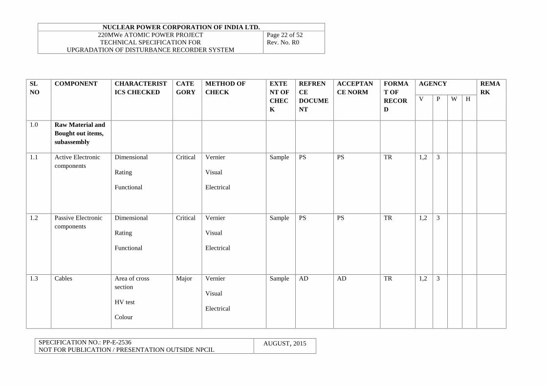
SLNO
COMPONENT CHARACTERISTICS CHECKED
CATEGORY
METHOD OFCHECK
EXTENT OFCHECK
REFRENCEDOCUMENT
ACCEPTANCE NORM
FORMAT OFRECORD
AGENCY REMARK
V P W H
1.0 Raw Material andBought out items,subassembly
1.1 Active Electroniccomponents
Dimensional
Rating
Functional
Critical Vernier
Visual
Electrical
Sample PS PS TR 1,2 3
1.2 Passive Electroniccomponents
Dimensional
Rating
Functional
Critical Vernier
Visual
Electrical
Sample PS PS TR 1,2 3
1.3 Cables Area of crosssection
HV test
Colour
Major Vernier
Visual
Electrical
Sample AD AD TR 1,2 3
NUCLEAR POWER CORPORATION OF INDIA LTD.220MWe ATOMIC POWER PROJECTTECHNICAL SPECIFICATION FOR
UPGRADATION OF DISTURBANCE RECORDER SYSTEM
Page 23 of 52Rev. No. R0
SPECIFICATION NO.: PP-E-2536NOT FOR PUBLICATION / PRESENTATION OUTSIDE NPCIL
AUGUST, 2015
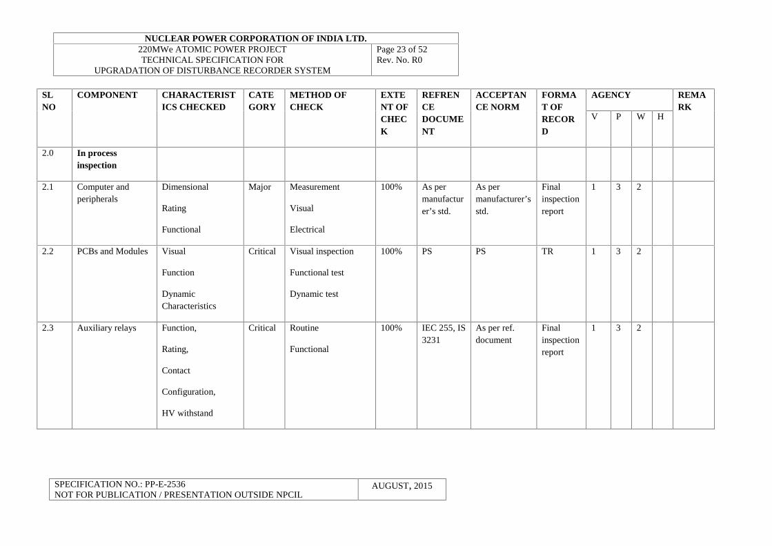
SLNO
COMPONENT CHARACTERISTICS CHECKED
CATEGORY
METHOD OFCHECK
EXTENT OFCHECK
REFRENCEDOCUMENT
ACCEPTANCE NORM
FORMAT OFRECORD
AGENCY REMARK
V P W H
2.0 In processinspection
2.1 Computer andperipherals
Dimensional
Rating
Functional
Major Measurement
Visual
Electrical
100% As permanufacturer’s std.
As permanufacturer’sstd.
Finalinspectionreport
1 3 2
2.2 PCBs and Modules Visual
Function
DynamicCharacteristics
Critical Visual inspection
Functional test
Dynamic test
100% PS PS TR 1 3 2
2.3 Auxiliary relays Function,
Rating,
Contact
Configuration,
HV withstand
Critical Routine
Functional
100% IEC 255, IS3231
As per ref.document
Finalinspectionreport
1 3 2
NUCLEAR POWER CORPORATION OF INDIA LTD.220MWe ATOMIC POWER PROJECTTECHNICAL SPECIFICATION FOR
UPGRADATION OF DISTURBANCE RECORDER SYSTEM
Page 24 of 52Rev. No. R0
SPECIFICATION NO.: PP-E-2536NOT FOR PUBLICATION / PRESENTATION OUTSIDE NPCIL
AUGUST, 2015
SLNO
COMPONENT CHARACTERISTICS CHECKED
CATEGORY
METHOD OFCHECK
EXTENT OFCHECK
REFRENCEDOCUMENT
ACCEPTANCE NORM
FORMAT OFRECORD
AGENCY REMARK
V P W H
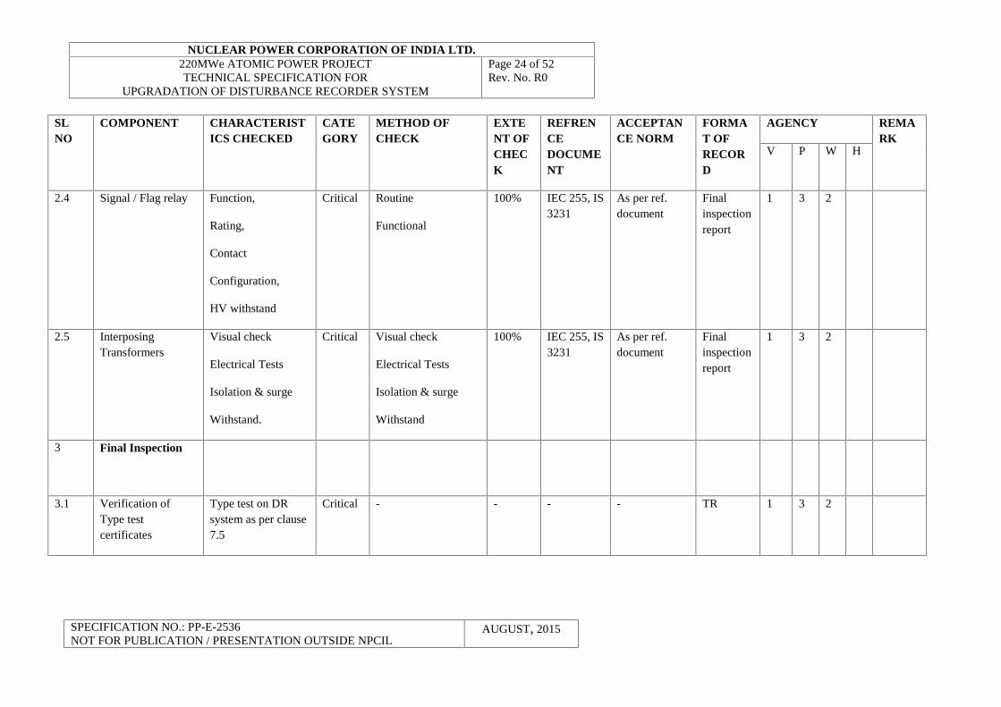
2.4 Signal / Flag relay Function,
Rating,
Contact
Configuration,
HV withstand
Critical Routine
Functional
100% IEC 255, IS3231
As per ref.document
Finalinspectionreport
1 3 2
2.5 InterposingTransformers
Visual check
Electrical Tests
Isolation & surge
Withstand.
Critical Visual check
Electrical Tests
Isolation & surge
Withstand
100% IEC 255, IS3231
As per ref.document
Finalinspectionreport
1 3 2
3 Final Inspection
3.1 Verification ofType testcertificates
Type test on DRsystem as per clause7.5
Critical - - - - TR 1 3 2
NUCLEAR POWER CORPORATION OF INDIA LTD.220MWe ATOMIC POWER PROJECTTECHNICAL SPECIFICATION FOR
UPGRADATION OF DISTURBANCE RECORDER SYSTEM
Page 25 of 52Rev. No. R0
SPECIFICATION NO.: PP-E-2536NOT FOR PUBLICATION / PRESENTATION OUTSIDE NPCIL
AUGUST, 2015
SLNO
COMPONENT CHARACTERISTICS CHECKED
CATEGORY
METHOD OFCHECK
EXTENT OFCHECK
REFRENCEDOCUMENT
ACCEPTANCE NORM
FORMAT OFRECORD
AGENCY REMARK
V P W H
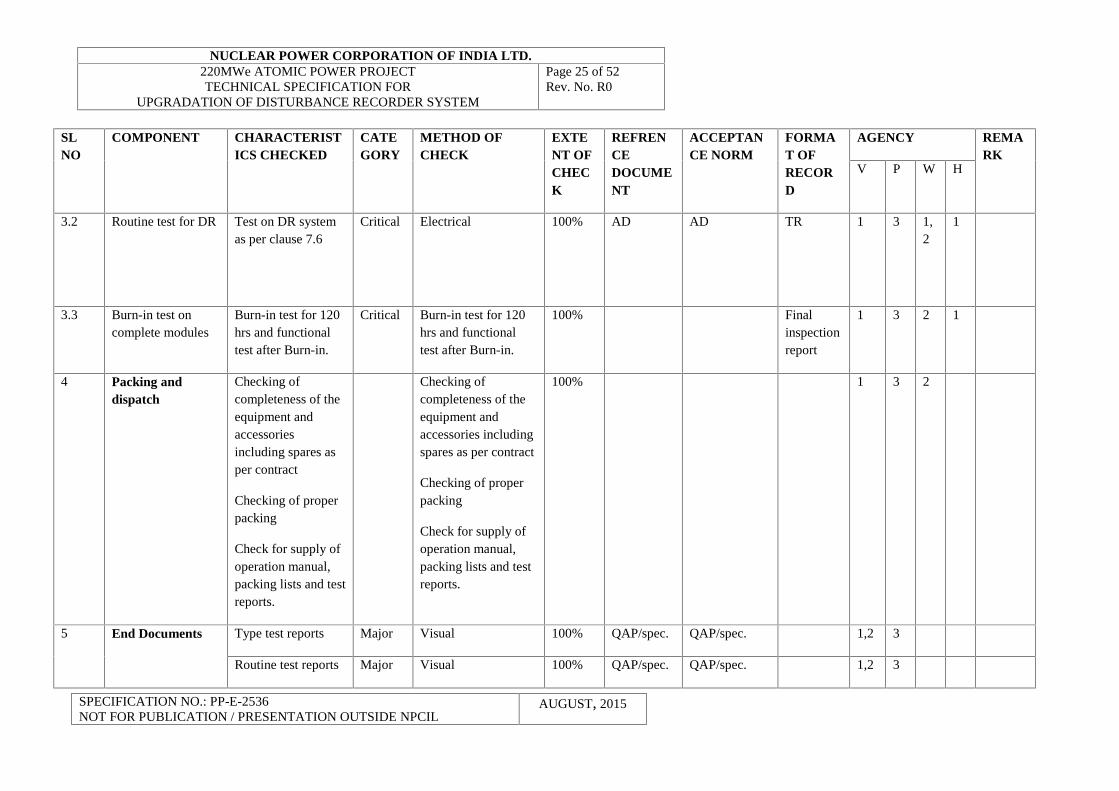
3.2 Routine test for DR Test on DR systemas per clause 7.6
Critical Electrical 100% AD AD TR 1 3 1,2
1
3.3 Burn-in test oncomplete modules
Burn-in test for 120hrs and functionaltest after Burn-in.
Critical Burn-in test for 120hrs and functionaltest after Burn-in.
100% Finalinspectionreport
1 3 2 1
4 Packing anddispatch
Checking ofcompleteness of theequipment andaccessoriesincluding spares asper contract
Checking of properpacking
Check for supply ofoperation manual,packing lists and testreports.
Checking ofcompleteness of theequipment andaccessories includingspares as per contract
Checking of properpacking
Check for supply ofoperation manual,packing lists and testreports.
100% 1 3 2
5 End Documents Type test reports Major Visual 100% QAP/spec. QAP/spec. 1,2 3
Routine test reports Major Visual 100% QAP/spec. QAP/spec. 1,2 3
NUCLEAR POWER CORPORATION OF INDIA LTD.220MWe ATOMIC POWER PROJECTTECHNICAL SPECIFICATION FOR
UPGRADATION OF DISTURBANCE RECORDER SYSTEM
Page 26 of 52Rev. No. R0
SPECIFICATION NO.: PP-E-2536NOT FOR PUBLICATION / PRESENTATION OUTSIDE NPCIL
AUGUST, 2015
SLNO
COMPONENT CHARACTERISTICS CHECKED
CATEGORY
METHOD OFCHECK
EXTENT OFCHECK
REFRENCEDOCUMENT
ACCEPTANCE NORM
FORMAT OFRECORD
AGENCY REMARK
V P W H
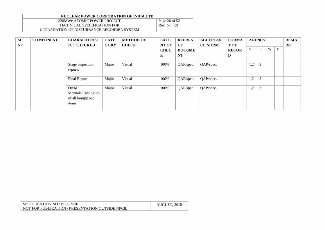
Stage inspectionreports
Major Visual 100% QAP/spec. QAP/spec. 1,2 3
Final Report Major Visual 100% QAP/spec. QAP/spec. 1,2 3
O&MManuals/Cataloguesof all bought outitems.
Major Visual 100% QAP/spec. QAP/spec. 1,2 3
NUCLEAR POWER CORPORATION OF INDIA LTD.220MWe ATOMIC POWER PROJECTTECHNICAL SPECIFICATION FOR
UPGRADATION OF DISTURBANCE RECORDER SYSTEM
Page 27 of 52Rev. No. R0
SPECIFICATION NO.: PP-E-2536NOT FOR PUBLICATION / PRESENTATION OUTSIDE NPCIL
AUGUST, 2015
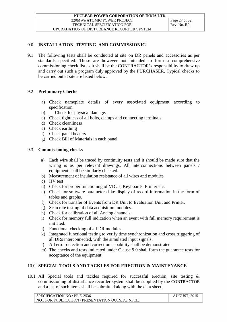
9.0 INSTALLATION, TESTING AND COMMISSIONIG
9.1 The following tests shall be conducted at site on DR panels and accessories as perstandards specified. These are however not intended to form a comprehensivecommissioning check list as it shall be the CONTRACTOR’s responsibility to draw upand carry out such a program duly approved by the PURCHASER. Typical checks tobe carried out at site are listed below.
9.2 Preliminary Checks
a) Check nameplate details of every associated equipment according tospecification.
b) Check for physical damage.c) Check tightness of all bolts, clamps and connecting terminals.d) Check cleanlinesse) Check earthingf) Check panel heaters.g) Check Bill of Materials in each panel
9.3 Commissioning checks
a) Each wire shall be traced by continuity tests and it should be made sure that thewiring is as per relevant drawings. All interconnections between panels /equipment shall be similarly checked.
b) Measurement of insulation resistance of all wires and modulesc) HV testd) Check for proper functioning of VDUs, Keyboards, Printer etc.e) Check for software parameters like display of record information in the form of
tables and graphs.f) Check for transfer of Events from DR Unit to Evaluation Unit and Printer.g) Scan rate testing of data acquisition modules.h) Check for calibration of all Analog channels.i) Check for memory full indication when an event with full memory requirement is
initiated.j) Functional checking of all DR modules.k) Integrated functional testing to verify time synchronization and cross triggering of
all DRs interconnected, with the simulated input signals.l) All error detection and correction capability shall be demonstrated.m) The checks and tests indicated under Clause 9.0 shall form the guarantee tests for
acceptance of the equipment
10.0 SPECIAL TOOLS AND TACKLES FOR ERECTION & MAINTENANCE
10.1 All Special tools and tackles required for successful erection, site testing &commissioning of disturbance recorder system shall be supplied by the CONTRACTORand a list of such items shall be submitted along with the data sheet.
NUCLEAR POWER CORPORATION OF INDIA LTD.220MWe ATOMIC POWER PROJECTTECHNICAL SPECIFICATION FOR
UPGRADATION OF DISTURBANCE RECORDER SYSTEM
Page 28 of 52Rev. No. R0
SPECIFICATION NO.: PP-E-2536NOT FOR PUBLICATION / PRESENTATION OUTSIDE NPCIL
AUGUST, 2015
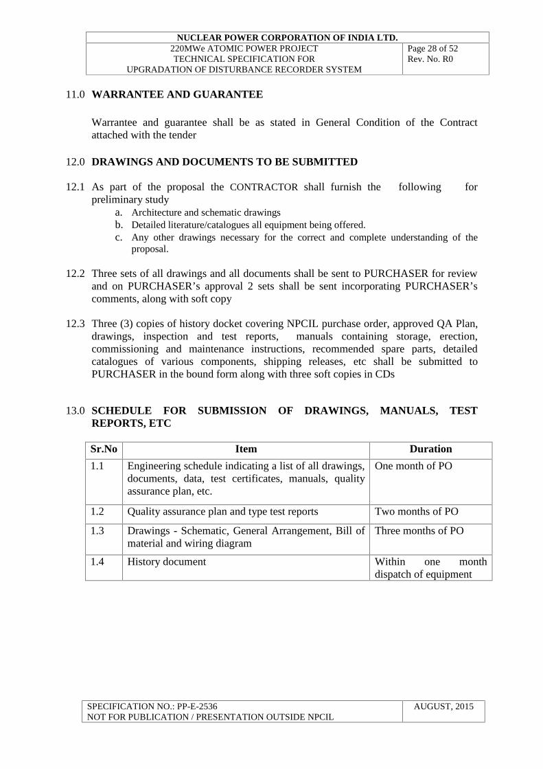
11.0 WARRANTEE AND GUARANTEE
Warrantee and guarantee shall be as stated in General Condition of the Contractattached with the tender
12.0 DRAWINGS AND DOCUMENTS TO BE SUBMITTED
12.1 As part of the proposal the CONTRACTOR shall furnish the following forpreliminary study
a. Architecture and schematic drawingsb. Detailed literature/catalogues all equipment being offered.c. Any other drawings necessary for the correct and complete understanding of the
proposal.
12.2 Three sets of all drawings and all documents shall be sent to PURCHASER for reviewand on PURCHASER’s approval 2 sets shall be sent incorporating PURCHASER’scomments, along with soft copy
12.3 Three (3) copies of history docket covering NPCIL purchase order, approved QA Plan,drawings, inspection and test reports, manuals containing storage, erection,commissioning and maintenance instructions, recommended spare parts, detailedcatalogues of various components, shipping releases, etc shall be submitted toPURCHASER in the bound form along with three soft copies in CDs
13.0 SCHEDULE FOR SUBMISSION OF DRAWINGS, MANUALS, TESTREPORTS, ETC
Sr.No Item Duration
1.1 Engineering schedule indicating a list of all drawings,documents, data, test certificates, manuals, qualityassurance plan, etc.
One month of PO
1.2 Quality assurance plan and type test reports Two months of PO
1.3 Drawings - Schematic, General Arrangement, Bill ofmaterial and wiring diagram
Three months of PO
1.4 History document Within one monthdispatch of equipment
NUCLEAR POWER CORPORATION OF INDIA LTD.220MWe ATOMIC POWER PROJECTTECHNICAL SPECIFICATION FOR
UPGRADATION OF DISTURBANCE RECORDER SYSTEM
Page 29 of 52Rev. No. R0
SPECIFICATION NO.: PP-E-2536NOT FOR PUBLICATION / PRESENTATION OUTSIDE NPCIL
AUGUST, 2015
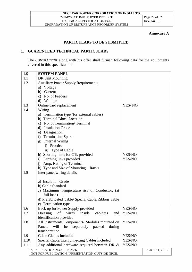
Annexure A
PARTICULARS TO BE SUBMITTED
1. GUARENTEED TECHNICAL PARTICULARS
The CONTRACTOR along with his offer shall furnish following data for the equipmentscovered in this specification:
1.0 SYSTEM PANEL1.1 DR Unit Mounting1.2 Auxiliary Power Supply Requirements
a) Voltageb) Currentc) No. of Feedersd) Wattage
1.3 Online card replacement YES/ NO1.4 Wiring
a) Termination type (for external cables)b) Terminal Block Locationc) No. of Termination/ Terminald) Insulation Gradee) Designationf) Termination Spareg) Internal Wiring
i) Practiceii) Type of Cable
h) Shorting links for CTs providedi) Earthing links providedj) Amp. Rating of Terminalk) Type and Size of Mounting Racks
YES/NOYES/NO
1.5 Inter panel wiring details
a) Insulation Gradeb) Cable Standardc) Maximum Temperature rise of Conductor. (at
full load)d) Prefabricated cable/ Special Cable/Ribbon cablee) Termination type
1.6 Back up for Power Supply provided YES/NO1.7 Dressing of wires inside cabinets and
identification providedYES/NO
1.8 All Instruments/Components/ Modules mounted onPanels will be separately packed duringtransportation.
YES/NO
1.9 Cable Glands included YES/NO1.10 Special Cable/Interconnecting Cables included YES/NO1.11 Any additional hardware required between DR & YES/NO
NUCLEAR POWER CORPORATION OF INDIA LTD.220MWe ATOMIC POWER PROJECTTECHNICAL SPECIFICATION FOR
UPGRADATION OF DISTURBANCE RECORDER SYSTEM
Page 30 of 52Rev. No. R0
SPECIFICATION NO.: PP-E-2536NOT FOR PUBLICATION / PRESENTATION OUTSIDE NPCIL
AUGUST, 2015
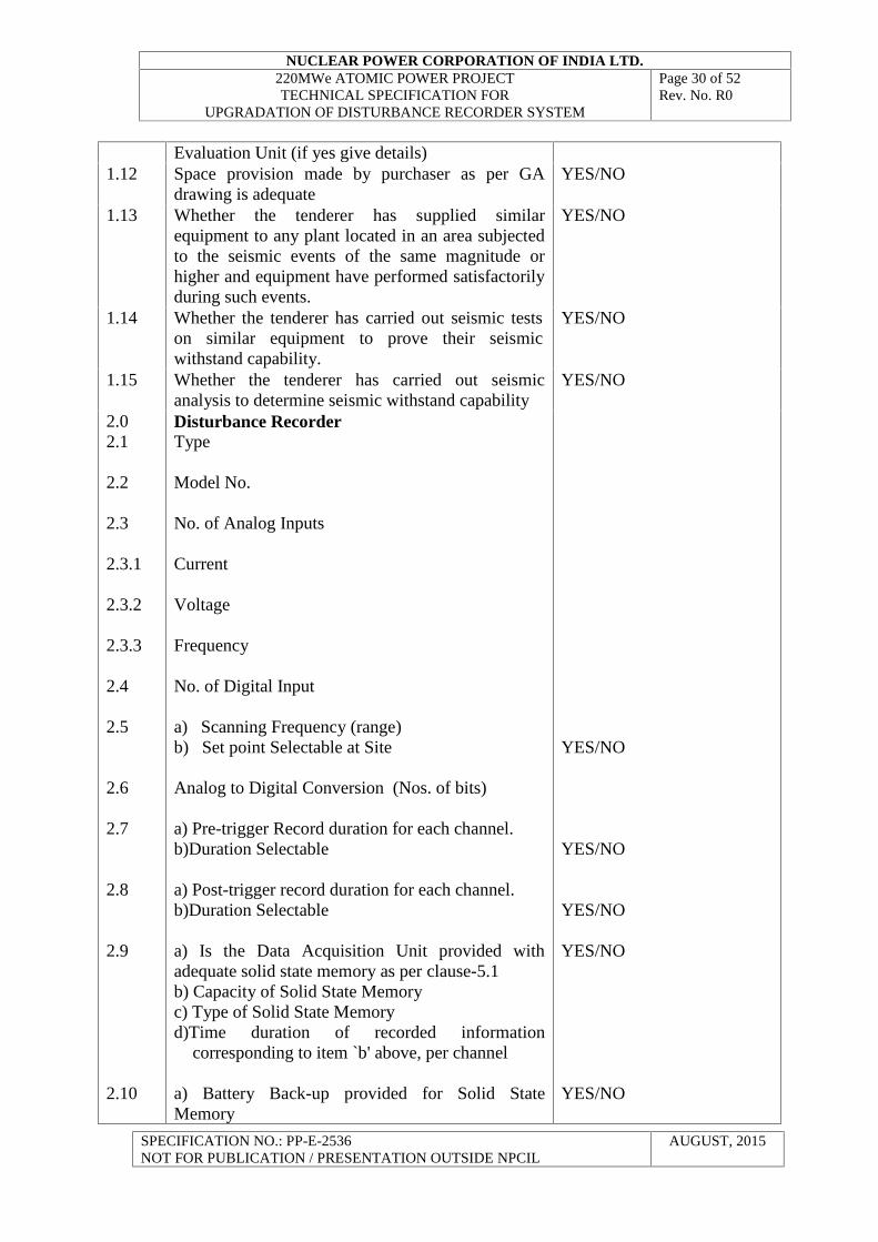
Evaluation Unit (if yes give details)1.12 Space provision made by purchaser as per GA
drawing is adequateYES/NO
1.13 Whether the tenderer has supplied similarequipment to any plant located in an area subjectedto the seismic events of the same magnitude orhigher and equipment have performed satisfactorilyduring such events.
YES/NO
1.14 Whether the tenderer has carried out seismic testson similar equipment to prove their seismicwithstand capability.
YES/NO
1.15 Whether the tenderer has carried out seismicanalysis to determine seismic withstand capability
YES/NO
2.02.1
2.2
2.3
2.3.1
2.3.2
2.3.3
2.4
2.5
2.6
2.7
2.8
2.9
2.10
Disturbance RecorderType
Model No.
No. of Analog Inputs
Current
Voltage
Frequency
No. of Digital Input
a) Scanning Frequency (range)b) Set point Selectable at Site
Analog to Digital Conversion (Nos. of bits)
a) Pre-trigger Record duration for each channel.b)Duration Selectable
a) Post-trigger record duration for each channel.b)Duration Selectable
a) Is the Data Acquisition Unit provided withadequate solid state memory as per clause-5.1b) Capacity of Solid State Memoryc) Type of Solid State Memoryd)Time duration of recorded information
corresponding to item `b' above, per channel
a) Battery Back-up provided for Solid StateMemory
YES/NO
YES/NO
YES/NO
YES/NO
YES/NO
NUCLEAR POWER CORPORATION OF INDIA LTD.220MWe ATOMIC POWER PROJECTTECHNICAL SPECIFICATION FOR
UPGRADATION OF DISTURBANCE RECORDER SYSTEM
Page 31 of 52Rev. No. R0
SPECIFICATION NO.: PP-E-2536NOT FOR PUBLICATION / PRESENTATION OUTSIDE NPCIL
AUGUST, 2015
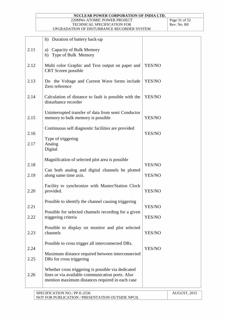
2.11
2.12
2.13
2.14
2.15
2.16
2.17
2.18
2.19
2.20
2.21
2.22
2.23
2.24
2.25
2.26
b) Duration of battery back-up
a) Capacity of Bulk Memoryb) Type of Bulk Memory
Multi color Graphic and Text output on paper andCRT Screen possible
Do the Voltage and Current Wave forms includeZero reference
Calculation of distance to fault is possible with thedisturbance recorder
Uninterrupted transfer of data from semi Conductormemory to bulk memory is possible
Continuous self diagnostic facilities are provided
Type of triggeringAnalogDigital
Magnification of selected plot area is possible
Can both analog and digital channels be plottedalong same time axis.
Facility to synchronize with Master/Station Clockprovided.
Possible to identify the channel causing triggering
Possible for selected channels recording for a giventriggering criteria
Possible to display on monitor and plot selectedchannels
Possible to cross trigger all interconnected DRs.
Maximum distance required between interconnectedDRs for cross triggering
Whether cross triggering is possible via dedicatedlines or via available communication ports. Alsomention maximum distances required in each case
YES/NO
YES/NO
YES/NO
YES/NO
YES/NO
YES/NO
YES/NO
YES/NO
YES/NO
YES/NO
YES/NO
YES/NO
NUCLEAR POWER CORPORATION OF INDIA LTD.220MWe ATOMIC POWER PROJECTTECHNICAL SPECIFICATION FOR
UPGRADATION OF DISTURBANCE RECORDER SYSTEM
Page 32 of 52Rev. No. R0
SPECIFICATION NO.: PP-E-2536NOT FOR PUBLICATION / PRESENTATION OUTSIDE NPCIL
AUGUST, 2015
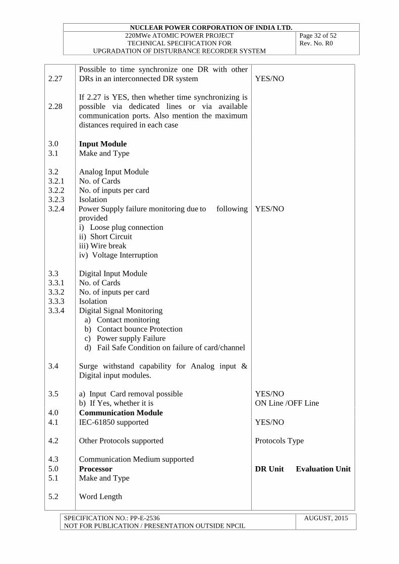
2.27
2.28
Possible to time synchronize one DR with otherDRs in an interconnected DR system
If 2.27 is YES, then whether time synchronizing ispossible via dedicated lines or via availablecommunication ports. Also mention the maximumdistances required in each case
YES/NO
3.0 Input Module3.1
3.23.2.13.2.23.2.33.2.4
3.33.3.13.3.23.3.33.3.4
3.4
3.5
Make and Type
Analog Input ModuleNo. of CardsNo. of inputs per cardIsolationPower Supply failure monitoring due to followingprovidedi) Loose plug connectionii) Short Circuitiii) Wire breakiv) Voltage Interruption
Digital Input ModuleNo. of CardsNo. of inputs per cardIsolationDigital Signal Monitoring
a) Contact monitoringb) Contact bounce Protectionc) Power supply Failured) Fail Safe Condition on failure of card/channel
Surge withstand capability for Analog input &Digital input modules.
a) Input Card removal possibleb) If Yes, whether it is
YES/NO
YES/NOON Line /OFF Line
4.0 Communication Module4.1
4.2
4.3
IEC-61850 supported
Other Protocols supported
Communication Medium supported
YES/NO
Protocols Type
5.05.1
5.2
ProcessorMake and Type
Word Length
DR Unit Evaluation Unit
NUCLEAR POWER CORPORATION OF INDIA LTD.220MWe ATOMIC POWER PROJECTTECHNICAL SPECIFICATION FOR
UPGRADATION OF DISTURBANCE RECORDER SYSTEM
Page 33 of 52Rev. No. R0
SPECIFICATION NO.: PP-E-2536NOT FOR PUBLICATION / PRESENTATION OUTSIDE NPCIL
AUGUST, 2015
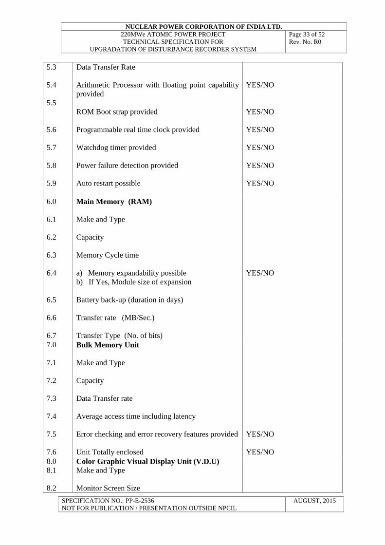
5.3
5.4
5.5
5.6
5.7
5.8
5.9
Data Transfer Rate
Arithmetic Processor with floating point capabilityprovided
ROM Boot strap provided
Programmable real time clock provided
Watchdog timer provided
Power failure detection provided
Auto restart possible
YES/NO
YES/NO
YES/NO
YES/NO
YES/NO
YES/NO
6.0
6.1
6.2
6.3
6.4
6.5
6.6
6.7
Main Memory (RAM)
Make and Type
Capacity
Memory Cycle time
a) Memory expandability possibleb) If Yes, Module size of expansion
Battery back-up (duration in days)
Transfer rate (MB/Sec.)
Transfer Type (No. of bits)
YES/NO
7.0
7.1
7.2
7.3
7.4
7.5
7.6
Bulk Memory Unit
Make and Type
Capacity
Data Transfer rate
Average access time including latency
Error checking and error recovery features provided
Unit Totally enclosed
YES/NO
YES/NO8.08.1
8.2
Color Graphic Visual Display Unit (V.D.U)Make and Type
Monitor Screen Size
NUCLEAR POWER CORPORATION OF INDIA LTD.220MWe ATOMIC POWER PROJECTTECHNICAL SPECIFICATION FOR
UPGRADATION OF DISTURBANCE RECORDER SYSTEM
Page 34 of 52Rev. No. R0
SPECIFICATION NO.: PP-E-2536NOT FOR PUBLICATION / PRESENTATION OUTSIDE NPCIL
AUGUST, 2015
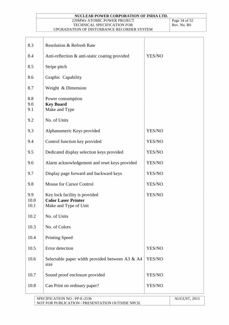
8.3
8.4
8.5
8.6
8.7
8.8
Resolution & Refresh Rate
Anti-reflection & anti-static coating provided
Stripe pitch
Graphic Capability
Weight & Dimension
Power consumption
YES/NO
9.09.1
9.2
9.3
9.4
9.5
9.6
9.7
9.8
9.9
Key BoardMake and Type
No. of Units
Alphanumeric Keys provided
Control function key provided
Dedicated display selection keys provided
Alarm acknowledgement and reset keys provided
Display page forward and backward keys
Mouse for Cursor Control
Key lock facility is provided
YES/NO
YES/NO
YES/NO
YES/NO
YES/NO
YES/NO
YES/NO10.010.1
10.2
10.3
10.4
10.5
10.6
10.7
10.8
Color Laser PrinterMake and Type of Unit
No. of Units
No. of Colors
Printing Speed
Error detection
Selectable paper width provided between A3 & A4size
Sound proof enclosure provided
Can Print on ordinary paper?
YES/NO
YES/NO
YES/NO
YES/NO

NUCLEAR POWER CORPORATION OF INDIA LTD.220MWe ATOMIC POWER PROJECTTECHNICAL SPECIFICATION FOR
UPGRADATION OF DISTURBANCE RECORDER SYSTEM
Page 35 of 52Rev. No. R0
SPECIFICATION NO.: PP-E-2536NOT FOR PUBLICATION / PRESENTATION OUTSIDE NPCIL
AUGUST, 2015
10.9
10.10
Dimensions and weight
Power consumption11.0
11.1
11.2
11.3
11.4
11.5
11.6
11.7
11.8
11.911.10
11.11
General
Detailed Literature for following items are enclosed
a) Disturbance recorderb) Input modulec) Processord) Main Memorye) Bulk Memory Unitf) Visual Display Unitg) Key Boardh) Color laser printeri) DVD-RW Drive
For DR/Evaluation unit Components
a) Mean time between failures (MTBF)b) Mean time to repair (MTTR)c) Recommended Test/calibration Voltaged) Recommended Test/calibration Frequencye) Impact of ageing on equipment performancef) Life in terms of number of years of operation
Special tools and devices for erection/maintenanceincluded (if Yes attach List)All functional, design and constructional featuresindicated in clause 4 and 5 are complied withAll drawings asked for in Section D 2.3 areenclosedAll routine tests as per clause 7.6 will be carriedouta) All type tests as per section clause 7.5 are carriedoutb) If Yes, copies of type tests certificates areenclosedc) If No, All type tests will be carried out and costsare indicatedAll required information as per clause 4 ofAnnexure-A are enclosedMounting tables /necessary furniture as per clause 4are being suppliedDetails of ICT/IVT and opto coupler enclosed.Type of electronic grounding required detailsenclosedDocument submitted to prove that software is
YES/NOYES/NOYES/NOYES/NOYES/NOYES/NOYES/NOYES/NOYES/NO
MONTHSDAYS
YES/NO
YES/NO
YES/NO
YES/NO
YES/NOYES/NO
YES/NO
YES/NO
YES/NO
YES/NOYES/NO
YES/NO
NUCLEAR POWER CORPORATION OF INDIA LTD.220MWe ATOMIC POWER PROJECTTECHNICAL SPECIFICATION FOR
UPGRADATION OF DISTURBANCE RECORDER SYSTEM
Page 36 of 52Rev. No. R0
SPECIFICATION NO.: PP-E-2536NOT FOR PUBLICATION / PRESENTATION OUTSIDE NPCIL
AUGUST, 2015
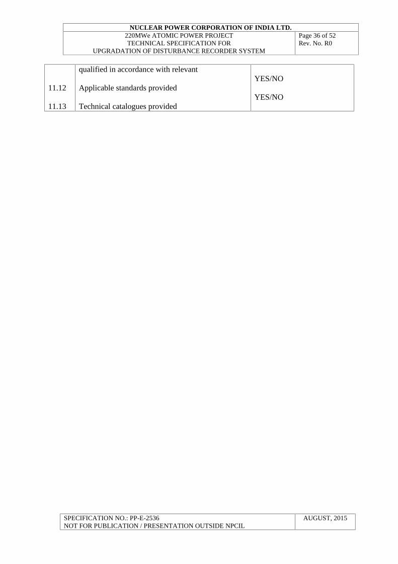
11.12
11.13
qualified in accordance with relevant
Applicable standards provided
Technical catalogues provided
YES/NO
YES/NO
NUCLEAR POWER CORPORATION OF INDIA LTD.220MWe ATOMIC POWER PROJECTTECHNICAL SPECIFICATION FOR
UPGRADATION OF DISTURBANCE RECORDER SYSTEM
Page 37 of 52Rev. No. R0
SPECIFICATION NO.: PP-E-2536NOT FOR PUBLICATION / PRESENTATION OUTSIDE NPCIL
AUGUST, 2015
2. SCHEDULE OF CONTRACTOR’S GENERAL PARTICULARS
The TENDERER shall furnish here the following general particulars of the Equipmentmanufacturers of all the equipment covered in this specification:
1.0 Name of the manufacturer :
2.0 Address of the manufacturer :
3.0 Fax No, Telephone no and email addresses of :the manufacturer
4.0 Name and designation of the officer of :the manufacturer to whom all reference shallbe made for expeditious technical co-ordination
5.0 Place of manufacture & assembly :
6.0 Current registration number with DGS & D :
7.0 Whether service facilities available, if so details :
8.0 Whether sufficient spares are available in stock :
9.0 Are all technical particulars called for filled up
10.0 Are all deviations pointed out in the schedule :of deviation
SIGNATURE ____________
DESIGNATION ____________
COMPANY ____________
DATE ____________
SEAL OF COMPANY
NUCLEAR POWER CORPORATION OF INDIA LTD.220MWe ATOMIC POWER PROJECTTECHNICAL SPECIFICATION FOR
UPGRADATION OF DISTURBANCE RECORDER SYSTEM
Page 38 of 52Rev. No. R0
SPECIFICATION NO.: PP-E-2536NOT FOR PUBLICATION / PRESENTATION OUTSIDE NPCIL
AUGUST, 2015
3. SCHEDULE OF CONTRACTOR’S EXPERIENCE
The CONTRACTOR shall furnish here a list of all similar jobs executed by him to whom areference may be made by the PURCHASER in case the PURCHASER considers such areference necessary.
S.No.Descriptionof workIncludingQty. of Items
Work orderor P.O. No.& date
Valueofwork
Deliverydate asper P.O.
Actualdate ofdelivery
Contact addressof Purchaser
SIGNATURE _________________
DESIGNATION _________________
COMPANY _________________
DATE _________________
SEAL OF COMPANY
NUCLEAR POWER CORPORATION OF INDIA LTD.220MWe ATOMIC POWER PROJECTTECHNICAL SPECIFICATION FOR
UPGRADATION OF DISTURBANCE RECORDER SYSTEM
Page 39 of 52Rev. No. R0
SPECIFICATION NO.: PP-E-2536NOT FOR PUBLICATION / PRESENTATION OUTSIDE NPCIL
AUGUST, 2015
4. PERFORMANCE DATA TO BE SUBMITTED ALONGWITH THE TENDER
CONTRACTOR shall submit for each type item offered, a tabulation indicating details ofequipment type tested, type tests carried out, severity levels, place of type testing, type testcertificate reference number, data of testing and whether any modification to the typetested equipment has been carried out after type testing and whether the type testedequipment and the equipment offered are identical.
SIGNATURE _________________
DESIGNATION _________________
COMPANY _________________
DATE _________________
SEAL OF COMPANY
NUCLEAR POWER CORPORATION OF INDIA LTD.220MWe ATOMIC POWER PROJECTTECHNICAL SPECIFICATION FOR
UPGRADATION OF DISTURBANCE RECORDER SYSTEM
Page 40 of 52Rev. No. R0
SPECIFICATION NO.: PP-E-2536NOT FOR PUBLICATION / PRESENTATION OUTSIDE NPCIL
AUGUST, 2015
5. SCHEDULE OF DEVIATIONS FROM TECHNICAL SPECIFICATION
All deviations from the technical specification shall be filled in by the CONTRACTORclause by clause in this schedule.
Section Clause No Deviation if any
The CONTRACTOR hereby certifies that the above mentioned are the onlydeviations from the technical specification of the enquiry.
SIGNATURE ________________
DESIGNATION ________________
COMPANY ________________
DATE ________________
SEAL OF COMPANY
NUCLEAR POWER CORPORATION OF INDIA LTD.220MWe ATOMIC POWER PROJECTTECHNICAL SPECIFICATION FOR
UPGRADATION OF DISTURBANCE RECORDER SYSTEM
Page 41 of 52Rev. No. R0
SPECIFICATION NO.: PP-E-2536NOT FOR PUBLICATION / PRESENTATION OUTSIDE NPCIL
AUGUST, 2015
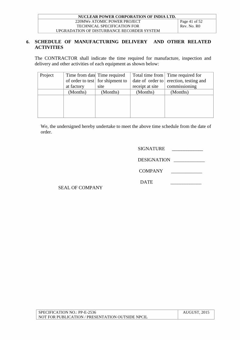
6. SCHEDULE OF MANUFACTURING DELIVERY AND OTHER RELATEDACTIVITIES
The CONTRACTOR shall indicate the time required for manufacture, inspection anddelivery and other activities of each equipment as shown below:
Project Time from dateof order to testat factory
Time requiredfor shipment tosite
Total time fromdate of order toreceipt at site
Time required forerection, testing andcommissioning
(Months) (Months) (Months) (Months)
We, the undersigned hereby undertake to meet the above time schedule from the date oforder.
SIGNATURE _____________
DESIGNATION _____________
COMPANY _____________
DATE _____________SEAL OF COMPANY
NUCLEAR POWER CORPORATION OF INDIA LTD.220MWe ATOMIC POWER PROJECTTECHNICAL SPECIFICATION FOR
UPGRADATION OF DISTURBANCE RECORDER SYSTEM
Page 42 of 52Rev. No. R0
SPECIFICATION NO.: PP-E-2536NOT FOR PUBLICATION / PRESENTATION OUTSIDE NPCIL
AUGUST, 2015
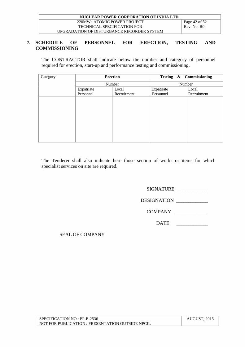
7. SCHEDULE OF PERSONNEL FOR ERECTION, TESTING ANDCOMMISSIONING
The CONTRACTOR shall indicate below the number and category of personnelrequired for erection, start-up and performance testing and commissioning.
Category Erection Testing & Commissioning
Number NumberExpatriatePersonnel
LocalRecruitment
ExpatriatePersonnel
LocalRecruitment
The Tenderer shall also indicate here those section of works or items for whichspecialist services on site are required.
SIGNATURE _____________
DESIGNATION _____________
COMPANY _____________
DATE _____________
SEAL OF COMPANY
NUCLEAR POWER CORPORATION OF INDIA LTD.220MWe ATOMIC POWER PROJECTTECHNICAL SPECIFICATION FOR
UPGRADATION OF DISTURBANCE RECORDER SYSTEM
Page 43 of 52Rev. No. R0
SPECIFICATION NO.: PP-E-2536NOT FOR PUBLICATION / PRESENTATION OUTSIDE NPCIL
AUGUST, 2015
8. SCHEDULE OF RECOMMENDED SPARES
SIGNATURE ________________
DESIGNATION _________________
COMPANY _________________
DATE _________________
SEAL OF COMPANY
NUCLEAR POWER CORPORATION OF INDIA LTD.220MWe ATOMIC POWER PROJECTTECHNICAL SPECIFICATION FOR
UPGRADATION OF DISTURBANCE RECORDER SYSTEM
Page 44 of 52Rev. No. R0
SPECIFICATION NO.: PP-E-2536NOT FOR PUBLICATION / PRESENTATION OUTSIDE NPCIL
AUGUST, 2015
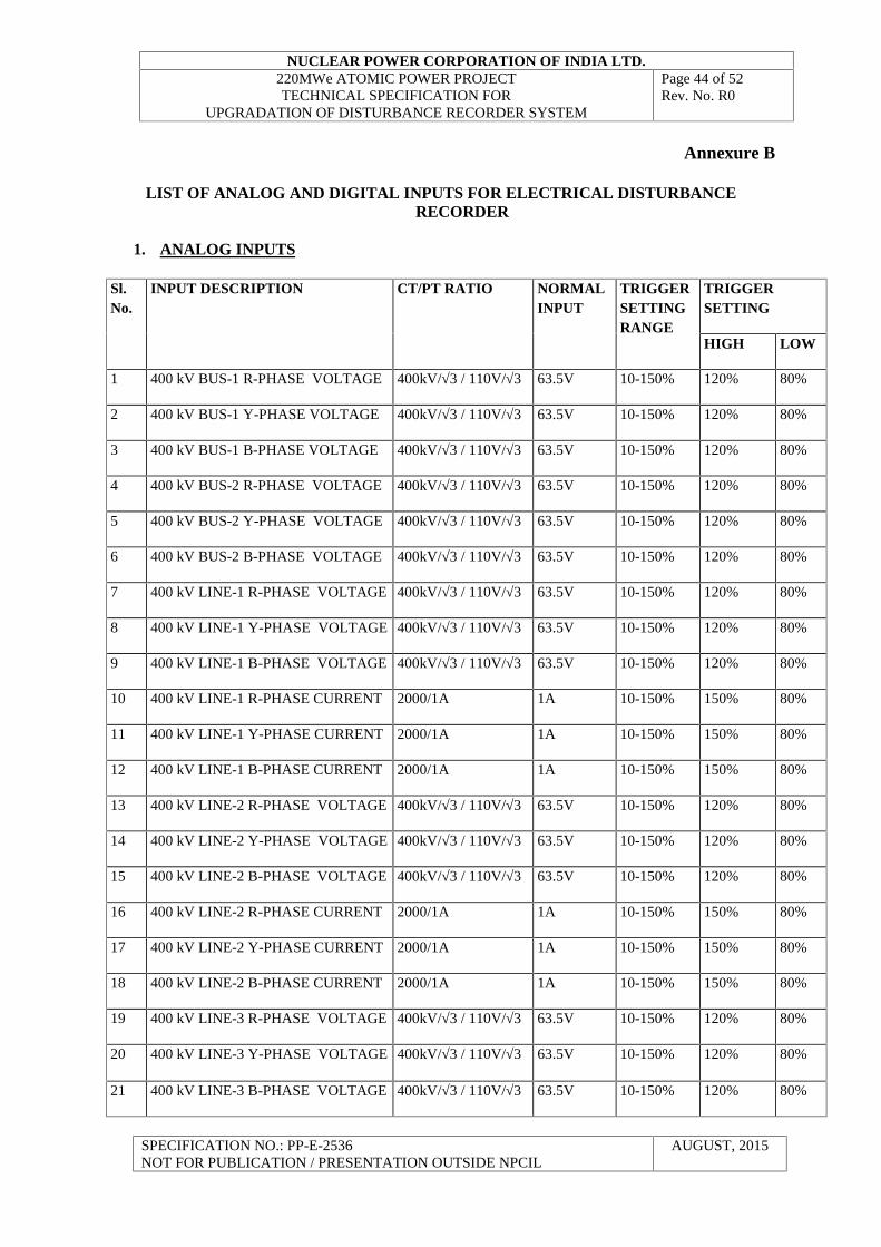
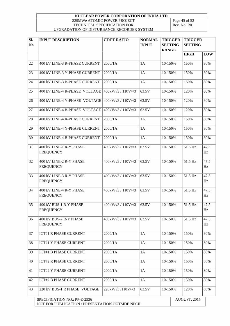
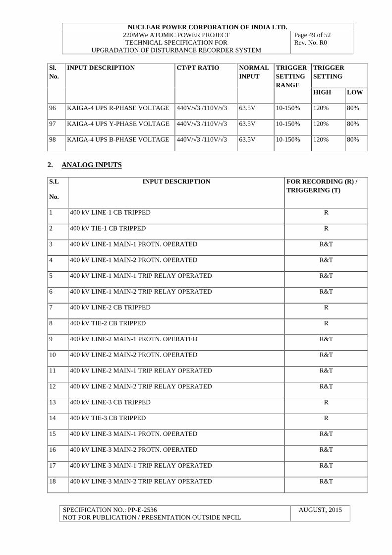
Annexure B
LIST OF ANALOG AND DIGITAL INPUTS FOR ELECTRICAL DISTURBANCERECORDER
1. ANALOG INPUTS
Sl.No.
INPUT DESCRIPTION CT/PT RATIO NORMALINPUT
TRIGGERSETTINGRANGE
TRIGGERSETTING
HIGH LOW
1 400 kV BUS-1 R-PHASE VOLTAGE 400kV/√3 / 110V/√3 63.5V 10-150% 120% 80%
2 400 kV BUS-1 Y-PHASE VOLTAGE 400kV/√3 / 110V/√3 63.5V 10-150% 120% 80%
3 400 kV BUS-1 B-PHASE VOLTAGE 400kV/√3 / 110V/√3 63.5V 10-150% 120% 80%
4 400 kV BUS-2 R-PHASE VOLTAGE 400kV/√3 / 110V/√3 63.5V 10-150% 120% 80%
5 400 kV BUS-2 Y-PHASE VOLTAGE 400kV/√3 / 110V/√3 63.5V 10-150% 120% 80%
6 400 kV BUS-2 B-PHASE VOLTAGE 400kV/√3 / 110V/√3 63.5V 10-150% 120% 80%
7 400 kV LINE-1 R-PHASE VOLTAGE 400kV/√3 / 110V/√3 63.5V 10-150% 120% 80%
8 400 kV LINE-1 Y-PHASE VOLTAGE 400kV/√3 / 110V/√3 63.5V 10-150% 120% 80%
9 400 kV LINE-1 B-PHASE VOLTAGE 400kV/√3 / 110V/√3 63.5V 10-150% 120% 80%
10 400 kV LINE-1 R-PHASE CURRENT 2000/1A 1A 10-150% 150% 80%
11 400 kV LINE-1 Y-PHASE CURRENT 2000/1A 1A 10-150% 150% 80%
12 400 kV LINE-1 B-PHASE CURRENT 2000/1A 1A 10-150% 150% 80%
13 400 kV LINE-2 R-PHASE VOLTAGE 400kV/√3 / 110V/√3 63.5V 10-150% 120% 80%
14 400 kV LINE-2 Y-PHASE VOLTAGE 400kV/√3 / 110V/√3 63.5V 10-150% 120% 80%
15 400 kV LINE-2 B-PHASE VOLTAGE 400kV/√3 / 110V/√3 63.5V 10-150% 120% 80%
16 400 kV LINE-2 R-PHASE CURRENT 2000/1A 1A 10-150% 150% 80%
17 400 kV LINE-2 Y-PHASE CURRENT 2000/1A 1A 10-150% 150% 80%
18 400 kV LINE-2 B-PHASE CURRENT 2000/1A 1A 10-150% 150% 80%
19 400 kV LINE-3 R-PHASE VOLTAGE 400kV/√3 / 110V/√3 63.5V 10-150% 120% 80%
20 400 kV LINE-3 Y-PHASE VOLTAGE 400kV/√3 / 110V/√3 63.5V 10-150% 120% 80%
21 400 kV LINE-3 B-PHASE VOLTAGE 400kV/√3 / 110V/√3 63.5V 10-150% 120% 80%
NUCLEAR POWER CORPORATION OF INDIA LTD.220MWe ATOMIC POWER PROJECTTECHNICAL SPECIFICATION FOR
UPGRADATION OF DISTURBANCE RECORDER SYSTEM
Page 45 of 52Rev. No. R0
SPECIFICATION NO.: PP-E-2536NOT FOR PUBLICATION / PRESENTATION OUTSIDE NPCIL
AUGUST, 2015
Sl.No.
INPUT DESCRIPTION CT/PT RATIO NORMALINPUT
TRIGGERSETTINGRANGE
TRIGGERSETTING
HIGH LOW
22 400 kV LINE-3 R-PHASE CURRENT 2000/1A 1A 10-150% 150% 80%
23 400 kV LINE-3 Y-PHASE CURRENT 2000/1A 1A 10-150% 150% 80%
24 400 kV LINE-3 B-PHASE CURRENT 2000/1A 1A 10-150% 150% 80%
25 400 kV LINE-4 R-PHASE VOLTAGE 400kV/√3 / 110V/√3 63.5V 10-150% 120% 80%
26 400 kV LINE-4 Y-PHASE VOLTAGE 400kV/√3 / 110V/√3 63.5V 10-150% 120% 80%
27 400 kV LINE-4 B-PHASE VOLTAGE 400kV/√3 / 110V/√3 63.5V 10-150% 120% 80%
28 400 kV LINE-4 R-PHASE CURRENT 2000/1A 1A 10-150% 150% 80%
29 400 kV LINE-4 Y-PHASE CURRENT 2000/1A 1A 10-150% 150% 80%
30 400 kV LINE-4 B-PHASE CURRENT 2000/1A 1A 10-150% 150% 80%
31 400 kV LINE-1 R-Y PHASEFREQUENCY
400kV/√3 / 110V/√3 63.5V 10-150% 51.5 Hz 47.5Hz
32 400 kV LINE-2 R-Y PHASEFREQUENCY
400kV/√3 / 110V/√3 63.5V 10-150% 51.5 Hz 47.5Hz
33 400 kV LINE-3 R-Y PHASEFREQUENCY
400kV/√3 / 110V/√3 63.5V 10-150% 51.5 Hz 47.5Hz
34 400 kV LINE-4 R-Y PHASEFREQUENCY
400kV/√3 / 110V/√3 63.5V 10-150% 51.5 Hz 47.5Hz
35 400 kV BUS-1 R-Y PHASEFREQUENCY
400kV/√3 / 110V/√3 63.5V 10-150% 51.5 Hz 47.5Hz
36 400 kV BUS-2 R-Y PHASEFREQUENCY
400kV/√3 / 110V/√3 63.5V 10-150% 51.5 Hz 47.5Hz
37 ICT#1 R PHASE CURRENT 2000/1A 1A 10-150% 150% 80%
38 ICT#1 Y PHASE CURRENT 2000/1A 1A 10-150% 150% 80%
39 ICT#1 B PHASE CURRENT 2000/1A 1A 10-150% 150% 80%
40 ICT#2 R PHASE CURRENT 2000/1A 1A 10-150% 150% 80%
41 ICT#2 Y PHASE CURRENT 2000/1A 1A 10-150% 150% 80%
42 ICT#2 B PHASE CURRENT 2000/1A 1A 10-150% 150% 80%
43 220 kV BUS-1 R PHASE VOLTAGE 220kV/√3 /110V/√3 63.5V 10-150% 120% 80%
NUCLEAR POWER CORPORATION OF INDIA LTD.220MWe ATOMIC POWER PROJECTTECHNICAL SPECIFICATION FOR
UPGRADATION OF DISTURBANCE RECORDER SYSTEM
Page 46 of 52Rev. No. R0
SPECIFICATION NO.: PP-E-2536NOT FOR PUBLICATION / PRESENTATION OUTSIDE NPCIL
AUGUST, 2015
Sl.No.
INPUT DESCRIPTION CT/PT RATIO NORMALINPUT
TRIGGERSETTINGRANGE
TRIGGERSETTING
HIGH LOW
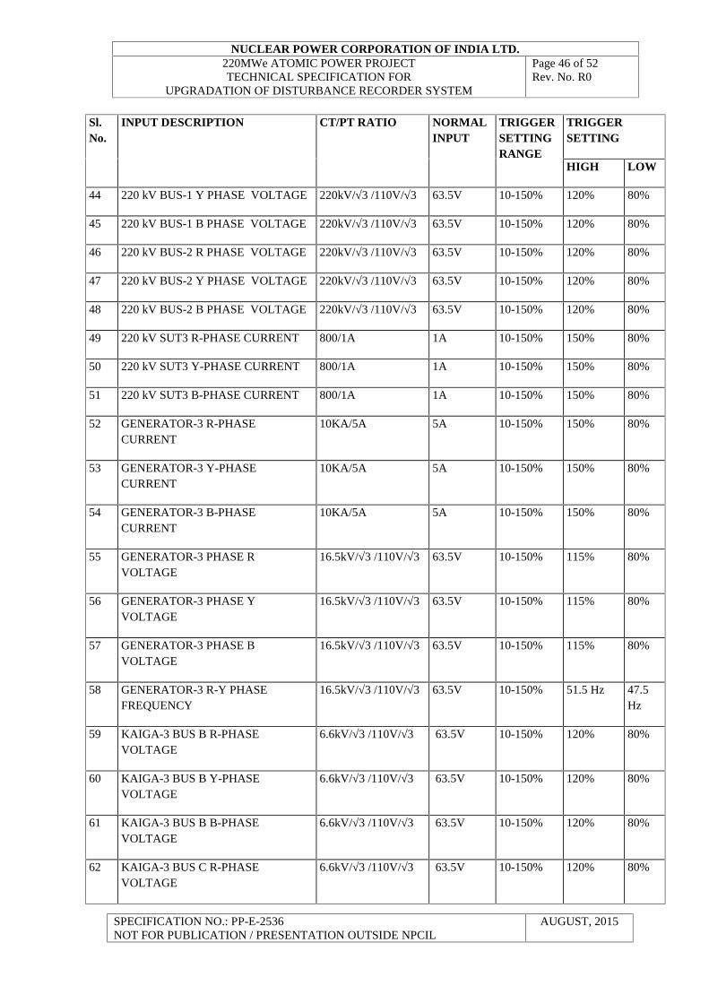
44 220 kV BUS-1 Y PHASE VOLTAGE 220kV/√3 /110V/√3 63.5V 10-150% 120% 80%
45 220 kV BUS-1 B PHASE VOLTAGE 220kV/√3 /110V/√3 63.5V 10-150% 120% 80%
46 220 kV BUS-2 R PHASE VOLTAGE 220kV/√3 /110V/√3 63.5V 10-150% 120% 80%
47 220 kV BUS-2 Y PHASE VOLTAGE 220kV/√3 /110V/√3 63.5V 10-150% 120% 80%
48 220 kV BUS-2 B PHASE VOLTAGE 220kV/√3 /110V/√3 63.5V 10-150% 120% 80%
49 220 kV SUT3 R-PHASE CURRENT 800/1A 1A 10-150% 150% 80%
50 220 kV SUT3 Y-PHASE CURRENT 800/1A 1A 10-150% 150% 80%
51 220 kV SUT3 B-PHASE CURRENT 800/1A 1A 10-150% 150% 80%
52 GENERATOR-3 R-PHASECURRENT
10KA/5A 5A 10-150% 150% 80%
53 GENERATOR-3 Y-PHASECURRENT
10KA/5A 5A 10-150% 150% 80%
54 GENERATOR-3 B-PHASECURRENT
10KA/5A 5A 10-150% 150% 80%
55 GENERATOR-3 PHASE RVOLTAGE
16.5kV/√3 /110V/√3 63.5V 10-150% 115% 80%
56 GENERATOR-3 PHASE YVOLTAGE
16.5kV/√3 /110V/√3 63.5V 10-150% 115% 80%
57 GENERATOR-3 PHASE BVOLTAGE
16.5kV/√3 /110V/√3 63.5V 10-150% 115% 80%
58 GENERATOR-3 R-Y PHASEFREQUENCY
16.5kV/√3 /110V/√3 63.5V 10-150% 51.5 Hz 47.5Hz
59 KAIGA-3 BUS B R-PHASEVOLTAGE
6.6kV/√3 /110V/√3 63.5V 10-150% 120% 80%
60 KAIGA-3 BUS B Y-PHASEVOLTAGE
6.6kV/√3 /110V/√3 63.5V 10-150% 120% 80%
61 KAIGA-3 BUS B B-PHASEVOLTAGE
6.6kV/√3 /110V/√3 63.5V 10-150% 120% 80%
62 KAIGA-3 BUS C R-PHASEVOLTAGE
6.6kV/√3 /110V/√3 63.5V 10-150% 120% 80%
NUCLEAR POWER CORPORATION OF INDIA LTD.220MWe ATOMIC POWER PROJECTTECHNICAL SPECIFICATION FOR
UPGRADATION OF DISTURBANCE RECORDER SYSTEM
Page 47 of 52Rev. No. R0
SPECIFICATION NO.: PP-E-2536NOT FOR PUBLICATION / PRESENTATION OUTSIDE NPCIL
AUGUST, 2015
Sl.No.
INPUT DESCRIPTION CT/PT RATIO NORMALINPUT
TRIGGERSETTINGRANGE
TRIGGERSETTING
HIGH LOW
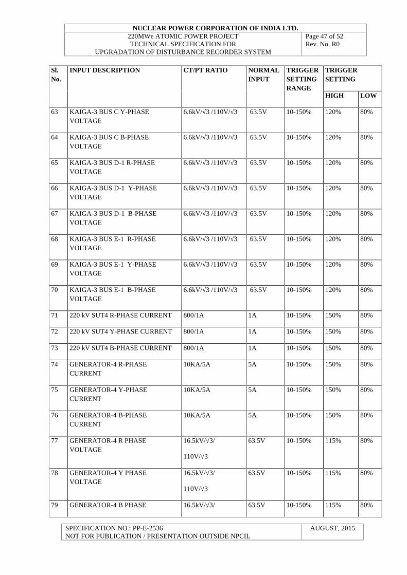
63 KAIGA-3 BUS C Y-PHASEVOLTAGE
6.6kV/√3 /110V/√3 63.5V 10-150% 120% 80%
64 KAIGA-3 BUS C B-PHASEVOLTAGE
6.6kV/√3 /110V/√3 63.5V 10-150% 120% 80%
65 KAIGA-3 BUS D-1 R-PHASEVOLTAGE
6.6kV/√3 /110V/√3 63.5V 10-150% 120% 80%
66 KAIGA-3 BUS D-1 Y-PHASEVOLTAGE
6.6kV/√3 /110V/√3 63.5V 10-150% 120% 80%
67 KAIGA-3 BUS D-1 B-PHASEVOLTAGE
6.6kV/√3 /110V/√3 63.5V 10-150% 120% 80%
68 KAIGA-3 BUS E-1 R-PHASEVOLTAGE
6.6kV/√3 /110V/√3 63.5V 10-150% 120% 80%
69 KAIGA-3 BUS E-1 Y-PHASEVOLTAGE
6.6kV/√3 /110V/√3 63.5V 10-150% 120% 80%
70 KAIGA-3 BUS E-1 B-PHASEVOLTAGE
6.6kV/√3 /110V/√3 63.5V 10-150% 120% 80%
71 220 kV SUT4 R-PHASE CURRENT 800/1A 1A 10-150% 150% 80%
72 220 kV SUT4 Y-PHASE CURRENT 800/1A 1A 10-150% 150% 80%
73 220 kV SUT4 B-PHASE CURRENT 800/1A 1A 10-150% 150% 80%
74 GENERATOR-4 R-PHASECURRENT
10KA/5A 5A 10-150% 150% 80%
75 GENERATOR-4 Y-PHASECURRENT
10KA/5A 5A 10-150% 150% 80%
76 GENERATOR-4 B-PHASECURRENT
10KA/5A 5A 10-150% 150% 80%
77 GENERATOR-4 R PHASEVOLTAGE
16.5kV/√3/
110V/√3
63.5V 10-150% 115% 80%
78 GENERATOR-4 Y PHASEVOLTAGE
16.5kV/√3/
110V/√3
63.5V 10-150% 115% 80%
79 GENERATOR-4 B PHASE 16.5kV/√3/ 63.5V 10-150% 115% 80%
NUCLEAR POWER CORPORATION OF INDIA LTD.220MWe ATOMIC POWER PROJECTTECHNICAL SPECIFICATION FOR
UPGRADATION OF DISTURBANCE RECORDER SYSTEM
Page 48 of 52Rev. No. R0
SPECIFICATION NO.: PP-E-2536NOT FOR PUBLICATION / PRESENTATION OUTSIDE NPCIL
AUGUST, 2015
Sl.No.
INPUT DESCRIPTION CT/PT RATIO NORMALINPUT
TRIGGERSETTINGRANGE
TRIGGERSETTING
HIGH LOW
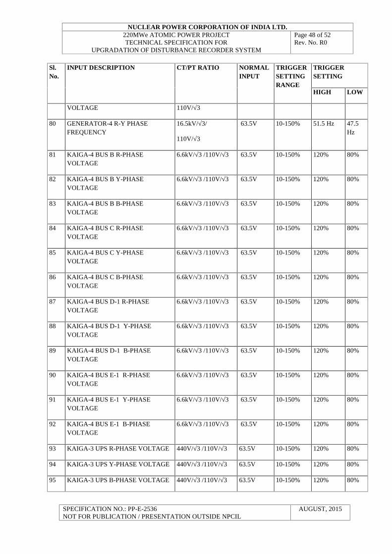
VOLTAGE 110V/√3
80 GENERATOR-4 R-Y PHASEFREQUENCY
16.5kV/√3/
110V/√3
63.5V 10-150% 51.5 Hz 47.5Hz
81 KAIGA-4 BUS B R-PHASEVOLTAGE
6.6kV/√3 /110V/√3 63.5V 10-150% 120% 80%
82 KAIGA-4 BUS B Y-PHASEVOLTAGE
6.6kV/√3 /110V/√3 63.5V 10-150% 120% 80%
83 KAIGA-4 BUS B B-PHASEVOLTAGE
6.6kV/√3 /110V/√3 63.5V 10-150% 120% 80%
84 KAIGA-4 BUS C R-PHASEVOLTAGE
6.6kV/√3 /110V/√3 63.5V 10-150% 120% 80%
85 KAIGA-4 BUS C Y-PHASEVOLTAGE
6.6kV/√3 /110V/√3 63.5V 10-150% 120% 80%
86 KAIGA-4 BUS C B-PHASEVOLTAGE
6.6kV/√3 /110V/√3 63.5V 10-150% 120% 80%
87 KAIGA-4 BUS D-1 R-PHASEVOLTAGE
6.6kV/√3 /110V/√3 63.5V 10-150% 120% 80%
88 KAIGA-4 BUS D-1 Y-PHASEVOLTAGE
6.6kV/√3 /110V/√3 63.5V 10-150% 120% 80%
89 KAIGA-4 BUS D-1 B-PHASEVOLTAGE
6.6kV/√3 /110V/√3 63.5V 10-150% 120% 80%
90 KAIGA-4 BUS E-1 R-PHASEVOLTAGE
6.6kV/√3 /110V/√3 63.5V 10-150% 120% 80%
91 KAIGA-4 BUS E-1 Y-PHASEVOLTAGE
6.6kV/√3 /110V/√3 63.5V 10-150% 120% 80%
92 KAIGA-4 BUS E-1 B-PHASEVOLTAGE
6.6kV/√3 /110V/√3 63.5V 10-150% 120% 80%
93 KAIGA-3 UPS R-PHASE VOLTAGE 440V/√3 /110V/√3 63.5V 10-150% 120% 80%
94 KAIGA-3 UPS Y-PHASE VOLTAGE 440V/√3 /110V/√3 63.5V 10-150% 120% 80%
95 KAIGA-3 UPS B-PHASE VOLTAGE 440V/√3 /110V/√3 63.5V 10-150% 120% 80%
NUCLEAR POWER CORPORATION OF INDIA LTD.220MWe ATOMIC POWER PROJECTTECHNICAL SPECIFICATION FOR
UPGRADATION OF DISTURBANCE RECORDER SYSTEM
Page 49 of 52Rev. No. R0
SPECIFICATION NO.: PP-E-2536NOT FOR PUBLICATION / PRESENTATION OUTSIDE NPCIL
AUGUST, 2015
Sl.No.
INPUT DESCRIPTION CT/PT RATIO NORMALINPUT
TRIGGERSETTINGRANGE
TRIGGERSETTING
HIGH LOW
96 KAIGA-4 UPS R-PHASE VOLTAGE 440V/√3 /110V/√3 63.5V 10-150% 120% 80%
97 KAIGA-4 UPS Y-PHASE VOLTAGE 440V/√3 /110V/√3 63.5V 10-150% 120% 80%
98 KAIGA-4 UPS B-PHASE VOLTAGE 440V/√3 /110V/√3 63.5V 10-150% 120% 80%
2. ANALOG INPUTS
S.L
No.
INPUT DESCRIPTION FOR RECORDING (R) /TRIGGERING (T)
1 400 kV LINE-1 CB TRIPPED R
2 400 kV TIE-1 CB TRIPPED R
3 400 kV LINE-1 MAIN-1 PROTN. OPERATED R&T
4 400 kV LINE-1 MAIN-2 PROTN. OPERATED R&T
5 400 kV LINE-1 MAIN-1 TRIP RELAY OPERATED R&T
6 400 kV LINE-1 MAIN-2 TRIP RELAY OPERATED R&T
7 400 kV LINE-2 CB TRIPPED R
8 400 kV TIE-2 CB TRIPPED R
9 400 kV LINE-2 MAIN-1 PROTN. OPERATED R&T
10 400 kV LINE-2 MAIN-2 PROTN. OPERATED R&T
11 400 kV LINE-2 MAIN-1 TRIP RELAY OPERATED R&T
12 400 kV LINE-2 MAIN-2 TRIP RELAY OPERATED R&T
13 400 kV LINE-3 CB TRIPPED R
14 400 kV TIE-3 CB TRIPPED R
15 400 kV LINE-3 MAIN-1 PROTN. OPERATED R&T
16 400 kV LINE-3 MAIN-2 PROTN. OPERATED R&T
17 400 kV LINE-3 MAIN-1 TRIP RELAY OPERATED R&T
18 400 kV LINE-3 MAIN-2 TRIP RELAY OPERATED R&T
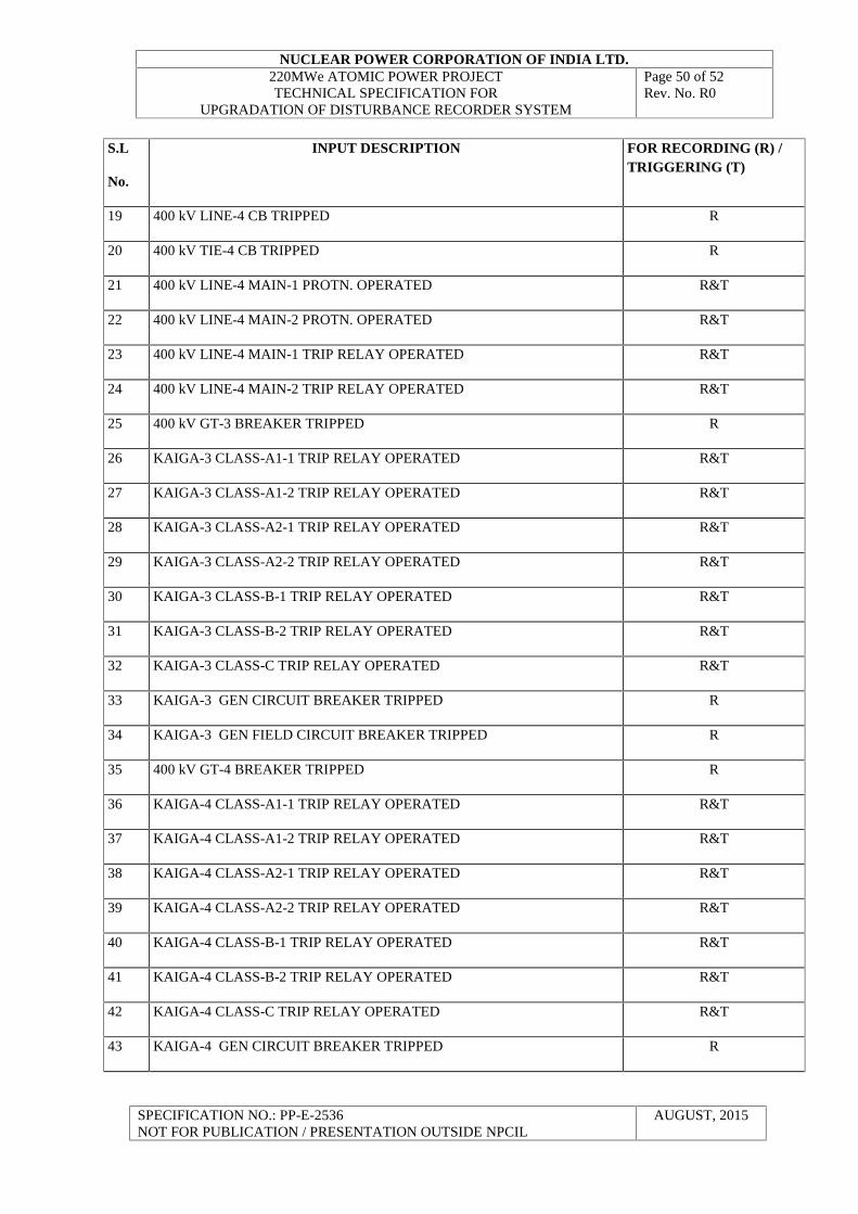
NUCLEAR POWER CORPORATION OF INDIA LTD.220MWe ATOMIC POWER PROJECTTECHNICAL SPECIFICATION FOR
UPGRADATION OF DISTURBANCE RECORDER SYSTEM
Page 50 of 52Rev. No. R0
SPECIFICATION NO.: PP-E-2536NOT FOR PUBLICATION / PRESENTATION OUTSIDE NPCIL
AUGUST, 2015
S.L
No.
INPUT DESCRIPTION FOR RECORDING (R) /TRIGGERING (T)
19 400 kV LINE-4 CB TRIPPED R
20 400 kV TIE-4 CB TRIPPED R
21 400 kV LINE-4 MAIN-1 PROTN. OPERATED R&T
22 400 kV LINE-4 MAIN-2 PROTN. OPERATED R&T
23 400 kV LINE-4 MAIN-1 TRIP RELAY OPERATED R&T
24 400 kV LINE-4 MAIN-2 TRIP RELAY OPERATED R&T
25 400 kV GT-3 BREAKER TRIPPED R
26 KAIGA-3 CLASS-A1-1 TRIP RELAY OPERATED R&T
27 KAIGA-3 CLASS-A1-2 TRIP RELAY OPERATED R&T
28 KAIGA-3 CLASS-A2-1 TRIP RELAY OPERATED R&T
29 KAIGA-3 CLASS-A2-2 TRIP RELAY OPERATED R&T
30 KAIGA-3 CLASS-B-1 TRIP RELAY OPERATED R&T
31 KAIGA-3 CLASS-B-2 TRIP RELAY OPERATED R&T
32 KAIGA-3 CLASS-C TRIP RELAY OPERATED R&T
33 KAIGA-3 GEN CIRCUIT BREAKER TRIPPED R
34 KAIGA-3 GEN FIELD CIRCUIT BREAKER TRIPPED R
35 400 kV GT-4 BREAKER TRIPPED R
36 KAIGA-4 CLASS-A1-1 TRIP RELAY OPERATED R&T
37 KAIGA-4 CLASS-A1-2 TRIP RELAY OPERATED R&T
38 KAIGA-4 CLASS-A2-1 TRIP RELAY OPERATED R&T
39 KAIGA-4 CLASS-A2-2 TRIP RELAY OPERATED R&T
40 KAIGA-4 CLASS-B-1 TRIP RELAY OPERATED R&T
41 KAIGA-4 CLASS-B-2 TRIP RELAY OPERATED R&T
42 KAIGA-4 CLASS-C TRIP RELAY OPERATED R&T
43 KAIGA-4 GEN CIRCUIT BREAKER TRIPPED R
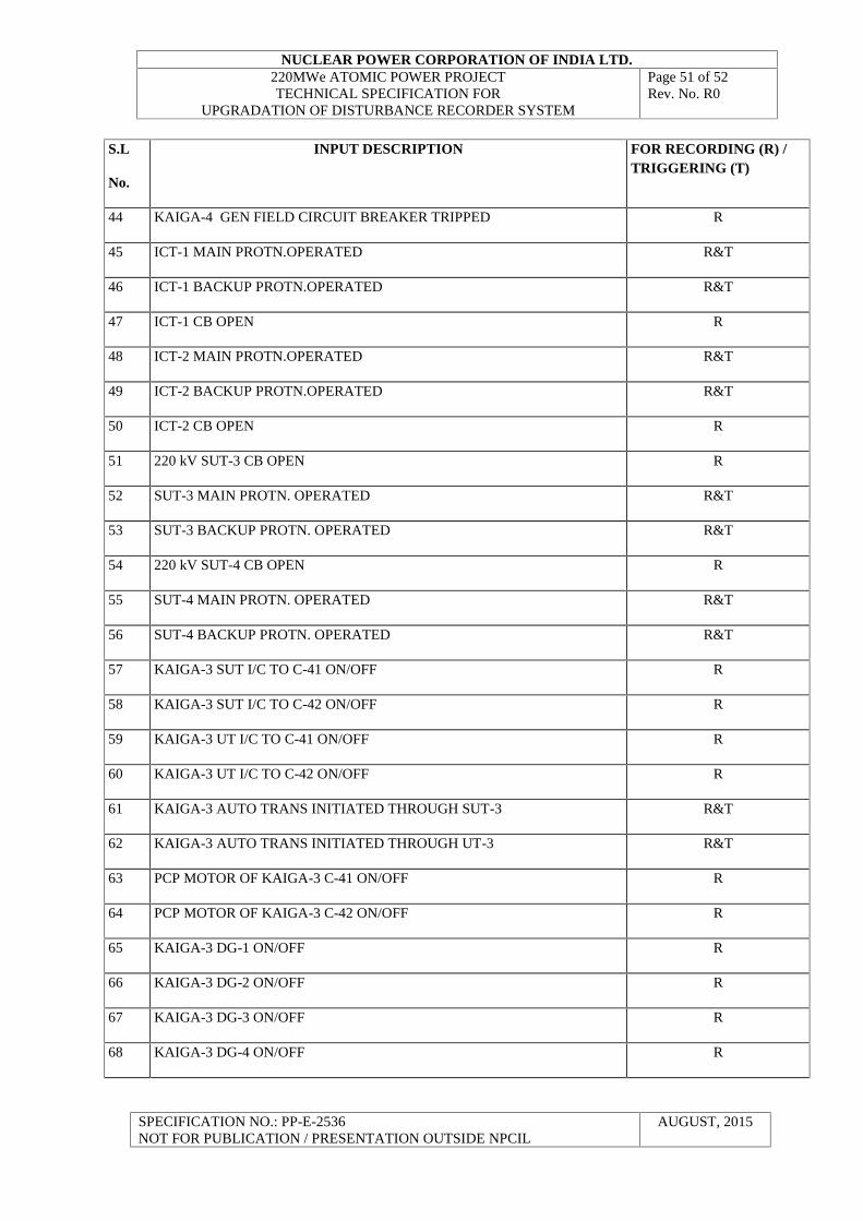
NUCLEAR POWER CORPORATION OF INDIA LTD.220MWe ATOMIC POWER PROJECTTECHNICAL SPECIFICATION FOR
UPGRADATION OF DISTURBANCE RECORDER SYSTEM
Page 51 of 52Rev. No. R0
SPECIFICATION NO.: PP-E-2536NOT FOR PUBLICATION / PRESENTATION OUTSIDE NPCIL
AUGUST, 2015
S.L
No.
INPUT DESCRIPTION FOR RECORDING (R) /TRIGGERING (T)
44 KAIGA-4 GEN FIELD CIRCUIT BREAKER TRIPPED R
45 ICT-1 MAIN PROTN.OPERATED R&T
46 ICT-1 BACKUP PROTN.OPERATED R&T
47 ICT-1 CB OPEN R
48 ICT-2 MAIN PROTN.OPERATED R&T
49 ICT-2 BACKUP PROTN.OPERATED R&T
50 ICT-2 CB OPEN R
51 220 kV SUT-3 CB OPEN R
52 SUT-3 MAIN PROTN. OPERATED R&T
53 SUT-3 BACKUP PROTN. OPERATED R&T
54 220 kV SUT-4 CB OPEN R
55 SUT-4 MAIN PROTN. OPERATED R&T
56 SUT-4 BACKUP PROTN. OPERATED R&T
57 KAIGA-3 SUT I/C TO C-41 ON/OFF R
58 KAIGA-3 SUT I/C TO C-42 ON/OFF R
59 KAIGA-3 UT I/C TO C-41 ON/OFF R
60 KAIGA-3 UT I/C TO C-42 ON/OFF R
61 KAIGA-3 AUTO TRANS INITIATED THROUGH SUT-3 R&T
62 KAIGA-3 AUTO TRANS INITIATED THROUGH UT-3 R&T
63 PCP MOTOR OF KAIGA-3 C-41 ON/OFF R
64 PCP MOTOR OF KAIGA-3 C-42 ON/OFF R
65 KAIGA-3 DG-1 ON/OFF R
66 KAIGA-3 DG-2 ON/OFF R
67 KAIGA-3 DG-3 ON/OFF R
68 KAIGA-3 DG-4 ON/OFF R
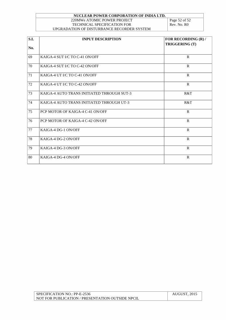
NUCLEAR POWER CORPORATION OF INDIA LTD.220MWe ATOMIC POWER PROJECTTECHNICAL SPECIFICATION FOR
UPGRADATION OF DISTURBANCE RECORDER SYSTEM
Page 52 of 52Rev. No. R0
SPECIFICATION NO.: PP-E-2536NOT FOR PUBLICATION / PRESENTATION OUTSIDE NPCIL
AUGUST, 2015
S.L
No.
INPUT DESCRIPTION FOR RECORDING (R) /TRIGGERING (T)
69 KAIGA-4 SUT I/C TO C-41 ON/OFF R
70 KAIGA-4 SUT I/C TO C-42 ON/OFF R
71 KAIGA-4 UT I/C TO C-41 ON/OFF R
72 KAIGA-4 UT I/C TO C-42 ON/OFF R
73 KAIGA-4 AUTO TRANS INITIATED THROUGH SUT-3 R&T
74 KAIGA-4 AUTO TRANS INITIATED THROUGH UT-3 R&T
75 PCP MOTOR OF KAIGA-4 C-41 ON/OFF R
76 PCP MOTOR OF KAIGA-4 C-42 ON/OFF R
77 KAIGA-4 DG-1 ON/OFF R
78 KAIGA-4 DG-2 ON/OFF R
79 KAIGA-4 DG-3 ON/OFF R
80 KAIGA-4 DG-4 ON/OFF R