Embed Size (px)
Citation preview

NOAA ARRA USVI Watershed Stabilization Project
Coral Bay Watershed Management Project –
Calabash Boom Drainage Improvements
National Oceanic and Atmospheric Administration Virgin Islands Resource Conservation & Development Council
Coral Bay Community Council
Patricia Reed Environmental Projects Manager
Coral Bay Community Council
March 31, 2012
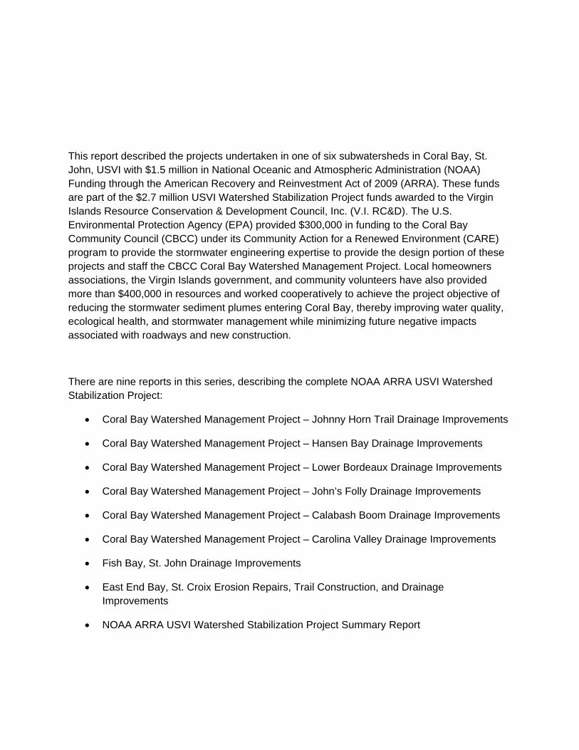
This report described the projects undertaken in one of six subwatersheds in Coral Bay, St. John, USVI with $1.5 million in National Oceanic and Atmospheric Administration (NOAA) Funding through the American Recovery and Reinvestment Act of 2009 (ARRA). These funds are part of the $2.7 million USVI Watershed Stabilization Project funds awarded to the Virgin Islands Resource Conservation & Development Council, Inc. (V.I. RC&D). The U.S. Environmental Protection Agency (EPA) provided $300,000 in funding to the Coral Bay Community Council (CBCC) under its Community Action for a Renewed Environment (CARE) program to provide the stormwater engineering expertise to provide the design portion of these projects and staff the CBCC Coral Bay Watershed Management Project. Local homeowners associations, the Virgin Islands government, and community volunteers have also provided more than $400,000 in resources and worked cooperatively to achieve the project objective of reducing the stormwater sediment plumes entering Coral Bay, thereby improving water quality, ecological health, and stormwater management while minimizing future negative impacts associated with roadways and new construction.
There are nine reports in this series, describing the complete NOAA ARRA USVI Watershed Stabilization Project:
Coral Bay Watershed Management Project – Johnny Horn Trail Drainage Improvements
Coral Bay Watershed Management Project – Hansen Bay Drainage Improvements
Coral Bay Watershed Management Project – Lower Bordeaux Drainage Improvements
Coral Bay Watershed Management Project – John’s Folly Drainage Improvements
Coral Bay Watershed Management Project – Calabash Boom Drainage Improvements
Coral Bay Watershed Management Project – Carolina Valley Drainage Improvements
Fish Bay, St. John Drainage Improvements
East End Bay, St. Croix Erosion Repairs, Trail Construction, and Drainage Improvements
NOAA ARRA USVI Watershed Stabilization Project Summary Report

Acknowledgements
Based on work by Joseph Mina, P.E., Christopher Laude, P.E, Barry Devine, Ph.D., Sarah Gray, Ph.D., Blake Parker, and Sharon Coldren.
Photos provided by the Coral Bay Community Council.
Overall project management was provided by the Virgin Islands Resource & Development Council and its Board of Directors listed below:
President - Diane Capehart Vice President - Olasee Davis Secretary - Marcia Taylor Treasurer - Dee Osinski (first year)/Olasee Davis At Large member - Paul Devine
Work would not have been possible without the contributed countless volunteer hours, including the project’s Principal Investigator Marcia Taylor who put a substantial amount of volunteer time into this project.
Work in Coral Bay would not have been possible without the Coral Bay Community Council, Inc., a 501(c)(3) organization, its volunteer Board members and many community volunteers. President and Executive Director, Sharon Coldren, spent three years as a volunteer working almost fulltime to implement this project.
Project management and project completion were facilitated by the technical expertise and project management skills of NOAA’s Restoration Center, specifically staff members Daphne MacFarlan and Julia Royster.

NOAA ARRA USVI WATERSHED STABILIZATION PROJECT Coral Bay Watershed Management Project – Calabash Boom Drainage Improvements
31 March 2012 www.CoralBayCommunityCouncil.org 1
Photo 1: Plume into Johnson Bay prior to drainage improvements (Shipwreck Ghut plume on the left; Calabash Boom Ghut
plume on the right).
Photo 2: Shipwreck Ghut Plume into Johnson Bay prior to drainage improvements.
Photo 3: Calabash Boom Ghut Plume into Johnson Bay prior to drainage improvements.
Executive Summary The Calabash Boom Drainage Basin contains two main ghuts that drain an uphill residential area with a steep, primarily unpaved road. Road grading modifications shifted some of the stormwater runoff to an adjacent ghut resulting in greater stormwater flows in this ghut. Additionally, construction of a housing complex in the Calabash Boom alluvial plain reduced its ability to clean sediment and infiltrate ghut flows from the surrounding hills. These actions plus erosion from the unpaved road increased sediment loads to Johnson Bay beginning in 2006, threatening coral reef habitat (Photos 1-3). The goal of this project is to stabilize an unpaved road and construct additional sediment and erosion control best management practices (BMPs); thereby, reducing sediment entering Johnson Bay.
In order to accomplish this goal, the Coral Bay Community Council (CBCC) proposed the following actions in the 2009 National Oceanic and Atmospheric Administration (NOAA) American Recovery and Reinvestment Act (ARRA) Coral Bay Workplan:
Limited areas of paving and BMP installation on the steep road; and,
Installation of a hydrodynamic separator and riprap apron at the Shipwreck Ghut outlet.
Ultimately, CBCC paved several road segments, installed nine waterbars, and constructed drainage channels, step pools, and check dams along Calabash Boom Road. Figure 1 shows the pre-existing and new stormwater structures, and other watershed features. The net effects are:
1) Reduced erosion of the road because several sections were paved and water is now diverted off the road; and,

NOAA ARRA USVI WATERSHED STABILIZATION PROJECT Coral Bay Watershed Management Project – Calabash Boom Drainage Improvements
31 March 2012 www.CoralBayCommunityCouncil.org 2
2) Step pools and check dams slow water velocities and allow sediment to settle out.
Shipwreck Ghut
Calabash Ghut
Johnson Bay
Figure 1: Calabash Boom Drainage Area and Watershed Features
Calabash Boom
Housing Complex
NOAA ARRA USVI WATERSHED STABILIZATION PROJECT Coral Bay Watershed Management Project – Calabash Boom Drainage Improvements
31 March 2012 www.CoralBayCommunityCouncil.org 3
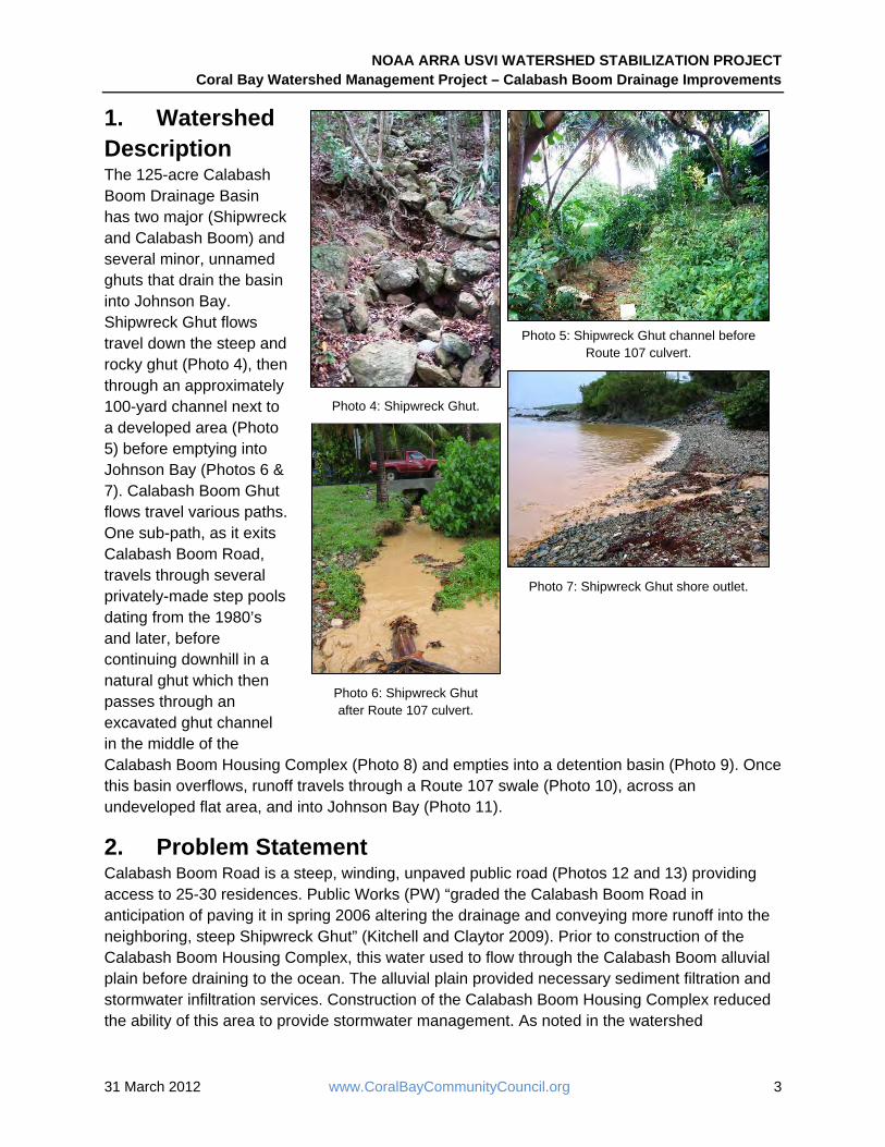
Photo 5: Shipwreck Ghut channel before Route 107 culvert.
Photo 7: Shipwreck Ghut shore outlet.
Photo 6: Shipwreck Ghut after Route 107 culvert.
Photo 4: Shipwreck Ghut.
1. Watershed Description The 125-acre Calabash Boom Drainage Basin has two major (Shipwreck and Calabash Boom) and several minor, unnamed ghuts that drain the basin into Johnson Bay. Shipwreck Ghut flows travel down the steep and rocky ghut (Photo 4), then through an approximately 100-yard channel next to a developed area (Photo 5) before emptying into Johnson Bay (Photos 6 & 7). Calabash Boom Ghut flows travel various paths. One sub-path, as it exits Calabash Boom Road, travels through several privately-made step pools dating from the 1980’s and later, before continuing downhill in a natural ghut which then passes through an excavated ghut channel in the middle of the Calabash Boom Housing Complex (Photo 8) and empties into a detention basin (Photo 9). Once this basin overflows, runoff travels through a Route 107 swale (Photo 10), across an undeveloped flat area, and into Johnson Bay (Photo 11).
2. Problem Statement Calabash Boom Road is a steep, winding, unpaved public road (Photos 12 and 13) providing access to 25-30 residences. Public Works (PW) “graded the Calabash Boom Road in anticipation of paving it in spring 2006 altering the drainage and conveying more runoff into the neighboring, steep Shipwreck Ghut” (Kitchell and Claytor 2009). Prior to construction of the Calabash Boom Housing Complex, this water used to flow through the Calabash Boom alluvial plain before draining to the ocean. The alluvial plain provided necessary sediment filtration and stormwater infiltration services. Construction of the Calabash Boom Housing Complex reduced the ability of this area to provide stormwater management. As noted in the watershed

NOAA ARRA USVI WATERSHED STABILIZATION PROJECT Coral Bay Watershed Management Project – Calabash Boom Drainage Improvements
31 March 2012 www.CoralBayCommunityCouncil.org 4
description, flows are now channeled through an excavated ghut (Photo 8) and into a detention basin (Photo 9) rather than sheet-flowing over land.
Shipwreck Ghut, prior to the 2006 PW grading, provided adequate infiltration and filtration services, as evidenced by healthy coral patches near the outlet. But after the grading, increased flows and greater amounts of sediment from the unpaved dirt road surface led to chronic, heavy
Photo 10: Route 107 swale. Photo 11: Calabash Boom Ghut outlet.
Photo 8: Calabash Boom Ghut running through housing complex.
Photo 9: Calabash Boom Housing Complex detention basin.
Photos 12-13: Steep unpaved Calabash Boom Road

NOAA ARRA USVI WATERSHED STABILIZATION PROJECT Coral Bay Watershed Management Project – Calabash Boom Drainage Improvements
31 March 2012 www.CoralBayCommunityCouncil.org 5
turbidity of ocean waters (see cover photo and Photos 14-15) and contributed to coral die-off of all the patch coral near the outflow by 2007.
3. Background and Project Planning
Research has shown that as development increased in Coral Bay so has sedimentation of the bay, thereby threatening the health of the bay and its marine habitats (Devine et al. 2003). In order to reduce this threat, the partner agencies, CBCC, NOAA, the Virgin Islands Department of Planning and Natural Resources (DPNR), the U.S. Environmental Protection Agency (EPA), and the Virgin Islands Resource Conservation and Development Council (V.I. RC&D), have aggressively spent the last five years planning and implementing actions to reduce sediment loads in Coral Bay.
Starting in 2007, NOAA funded the Coral Bay Watershed Management Plan (WMP) as a DPNR pilot watershed plan to provide a demonstration site for the whole U.S. Virgin Islands. Immediately upon publication of the WMP in 2008, CBCC applied for a $300,000 EPA Community for a Renewed Environment (CARE) grant, and received it in early 2009 to begin implementation of the WMP as part of the overall Coral Bay Watershed Management Project. The primary goal of the EPA CARE grant was to implement WMP Recommendation #1 – Provide direct, on-site technical assistance to watershed residents, businesses, developers, and others implementing watershed recommendations. To help with this recommendation the WMP discussed five actions, two of which CBCC implemented as part of the EPA CARE grant:
Near-Term Action 1.1: Use EPA CARE grant as seed money to support a 1-2 year, full-time hydrologist/watershed manager for Coral Bay.
Near-Term Action 1.4: DPNR and CBCC should consider providing resources needed to support new personnel (i.e. GIS, office basics, vehicle, etc.).
In spring 2009, working through a local nonprofit partner, V.I. RC&D, CBCC secured $1.5 million of NOAA ARRA grant funds. CBCC and V.I. RC&D used these funds to implement actions proposed in the NOAA ARRA Coral Bay Workplan prepared for the grant application, based on
Photo 14: Shipwreck Ghut plume into Johnson Bay.
Photo 15: Sediment-laden runoff from Shipwreck Ghut into Johnson Bay.

NOAA ARRA USVI WATERSHED STABILIZATION PROJECT Coral Bay Watershed Management Project – Calabash Boom Drainage Improvements
31 March 2012 www.CoralBayCommunityCouncil.org 6
the expertise provided by the newly hired CBCC Stormwater Engineer (see Section 4.1). These NOAA ARRA funds allowed for the restoration of natural drainage functions and paving of roads in six subwatersheds in Coral Bay in order to eliminate or reduce the sediment-laden stormwater runoff plumes entering the bay. These projects also implemented portions of WMP Recommendation #3 - Evaluate and repair erosion and drainage problems that are threatening property, damaging infrastructure, or delivering excessive sediment loads to Coral Bay. CBCC’s website contains a Project Overview of the USVI Watershed Stabilization Project in Coral Bay and a description of the Coral Bay Watershed Management Project.
In the NOAA ARRA Coral Bay Workplan, CBCC developed a list of watershed stabilization techniques appropriate for the Coral Bay environment (see Appendix A). These were used to formulate the following goals for the Calabash Boom Drainage Basin Project:
1. Reduce road damage and stabilize roadways from unmitigated flows (Strategy 4); and, 2. Construct additional stormwater BMPs to trap sediment (Strategy 4).
4. Project Implementation 4.1 Project Design CBCC hired Joseph Mina, P.E. as its Stormwater Engineer in 2009 using the EPA CARE grant funds to provide design expertise and recommendations. Initially he wrote a series of engineering design memos based on field conditions to help identify the key BMPs for local implementation. He also contributed significantly to writing the NOAA ARRA Coral Bay Workplan and prioritizing the detailed projects in it. The EPA CARE grant funded the engineering design phase, with the NOAA ARRA funding taking over for the field engineering and inspection, permitting, construction bidding, and field construction phases. V.I. RC&D was directly responsible for the construction phases of the Coral Bay NOAA ARRA projects. For personal reasons, Mr. Mina had to leave CBCC’s employment in June 2010 and CBCC hired Christopher Laude, P.E. to complete the design phase and implement the NOAA ARRA BMP projects over the following year.
4.2 BMP Selection Process CBCC initially divided the Calabash Boom Drainage Basin into two areas based on stormwater drainage locations in the basin. The NOAA ARRA Coral Bay Workplan included these areas as described in Table 1. In August 2009, Horsley Witten Group, using NOAA Coral Reef Program funds, was able to conduct a site assessment and provide concepts for stabilization/improvement options. “The purpose of this effort was not to develop detailed engineering designs or survey work; rather it was to meet NOAA’s and CBCC’s objective to kick start implementation of priority restoration projects recommended in the 2008 Coral Bay WMP and to stop a chronic source of sediment loading to the Bay” (Kitchell and Claytor 2009).
Mr. Mina took their November 2009 memorandum, and refined and amplified the recommendations in a February 2010 design memo. By March 2010, Mr. Mina had drafted a Scope of Work (Scope), Details, & Specifications document. The bid for this Scope was double the amount budgeted for the project so BMPs were reprioritized, reduced in scope, and rebid.
NOAA ARRA USVI WATERSHED STABILIZATION PROJECT Coral Bay Watershed Management Project – Calabash Boom Drainage Improvements
31 March 2012 www.CoralBayCommunityCouncil.org 7
The area of the Scope was reduced because it was discovered that utilities had been placed underground below the upper portion of Calabash Boom Road, without written location plans or locally-available sensing equipment to determine conduit location, thereby rendering it less safe to do construction work on that section of the roadway. In spring 2010, CBCC encouraged the formation of an informal Homeowners Association (HOA): the Calabash Boom Mountain Association. Although the road is a territorial public road, it is a low priority for PW maintenance and improvements. The HOA provided recommendations for problem areas, raised funds, and committed to doing future routine removal of sediment from the project’s step pools and waterbar areas. They also paid for installation of an additional waterbar in 2010 and graded the upper roadway in February/March 2011, spending about $15,000. They are currently providing continued maintenance of the stormwater BMPs along Calabash Boom Road.
For the Shipwreck area, the NOAA ARRA Coral Bay Workplan described a project that would include a hydrodynamic separator or custom baffle box with riprap aprons. By April 2010, the design included cleaning out the ghut channel, grading eroded banks, installing 3-4 step pools, and the hydrodynamic separator. The final Scope in April 2011 changed the step pools and channel work to installing two check dams and an inlet box, as well as the hydrodynamic separator. After design and permitting, this project was cancelled because (1) in the current environment PW would not commit to the vacuum truck maintenance required for a hydrodynamic separator; (2) another engineer questioned the design; and, (3) the tight time window for construction due to a neighboring restaurant’s busy season.
As a substitute for the cancelled Shipwreck Project, CBCC deployed the $75,000 in funds to extend the work on the Calabash Boom Road in the upper watershed. A Phase 2 Scope was drafted in June 2011, which included 302 feet of paving in several spots, installation of two waterbars, and over 500 feet of additional drainage channel excavation with construction of three check dams.
Tables 1 & 2 summarize the transition from actions proposed in the NOAA ARRA Coral Bay Workplan to the implemented actions by including dates for proposal, dates for construction, and any additional comments necessary. All engineering design documents have been included in Appendix A.
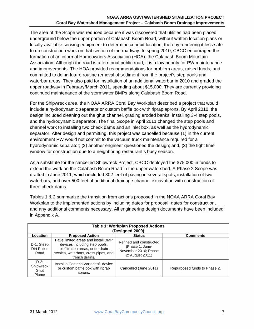
Table 1: Workplan Proposed Actions (Designed 2009)
Location Proposed Action Status Comments
D-1: Steep Dirt Public
Road
Pave limited areas and install BMP devices including step pools, biofiltration areas, underdrain
swales, waterbars, cross pipes, and trench drains.
Refined and constructed (Phase 1: June-
November 2010; Phase 2: August 2011)
D-2: Shipwreck
Ghut Plume
Install a Contech Vortechs® device or custom baffle box with riprap
aprons. Cancelled (June 2011) Repurposed funds to Phase 2.

NOAA ARRA USVI WATERSHED STABILIZATION PROJECT Coral Bay Watershed Management Project – Calabash Boom Drainage Improvements
31 March 2012 www.CoralBayCommunityCouncil.org 8
Table 2: Implemented Actions (Designed - Phase 1: March & August 2010; Phase 2: June 2011)
Location Implemented Action Status Comments
Calabash Boom Road
Construct 18-foot wide by 40 linear foot concrete pavement including
backfill from existing Reliance paving towards existing resident’s
driveway.
Constructed (Phase 1: June-November 2010)
The listed actions were implemented; however, the
overall design included much more paving and other BMPs
than could be implemented with limited NOAA ARRA funding.
At least $1 million more is needed to complete paving and
BMPs on this road.
Repair driveway intersection and excavate and pave roadside swale.
Construct 18-foot wide by 100 linear foot concrete pavement
including backfill at the first switchback.
Pave steep section of road just below driveway midway between the first and second switchbacks
downhill 150 feet.
Grade 2,340 linear feet of road and excavate roadside drainage
channel between first and second switchbacks.
Construct seven step pools in roadside drainage channel.
Install six concrete waterbars and a double utility pole waterbar in
various locations.
Excavate and pave 302 linear feet of roadway at various locations.
Constructed (Phase 2: August 2011)
Construct two waterbars.
Pave the second switchback.
Construct three check dams.
4.3 Problems Encountered/Overcome The original design for improvements produced bids costing about double the available funds. This was not a surprise because (1) it was the first project bid and CBCC did not estimate costs prior to the bid; and, (2) several years previously PW had estimated complete paving and stormwater BMPs for the 1.3-mile road at over $1.5 million.
In this project and others associated with NOAA ARRA funds, we generally found that we bid out a longer list than we expected to be able to fund, reviewed the bids, and then chose the elements that created the most cost-effective mix with the greatest potential sediment reduction.
The original Scope included one lane paving and unpaved pullouts and a wide grassed drivable shoulder. PW insisted that all paved areas needed widths of a minimum of 18 feet, with some exceptions of 16 feet, where the road cut was too narrow to allow for the 18-foot width. This policy dramatically reduced the length of the paved road area that was possible under the project budget.

NOAA ARRA USVI WATERSHED STABILIZATION PROJECT Coral Bay Watershed Management Project – Calabash Boom Drainage Improvements
31 March 2012 www.CoralBayCommunityCouncil.org 9
Because the roadway is public, CBCC only needed official permissions from PW and DPNR although it sought and gained written permission from private owners where the contractor might be doing something near or on adjacent private land. This process was undertaken to help assure that there was “full notice” and that contractors could work effectively with neighbors and not encounter problems during the construction process. This kind of inclusionary process is important to identify potential problems and avoid them – such as a special event (wedding, etc.), upcoming construction, advanced planning for the inconvenience of a blocked driveway, or one-way, delayed travel during the construction period.
4.4 Project Costs & Construction After taking into consideration site conditions, BMP costs, and available project funds, the final BMPs implemented included paving two switchbacks and other road segments, installing waterbars, and constructing roadside drainage channels, step pools, and check dams for a total cost of $185,926 over two phases plus $15,000 in additional work contributed by the Calabash Boom Mountain Association. Table 3 below details project costs for both phases of implemented BMP work. The sections below the table provide a more detailed description of construction activities. Appendix A has detailed design drawings.
Table 3: Calabash Boom Drainage Basin Project Costs Description Total Cost
Phase 1 Work Construct 18-foot wide by 40 linear foot concrete pavement including backfill from existing Reliance paving towards existing resident’s driveway.
$8,640
Repair driveway intersection and excavate and pave roadside swale. $4,740 Construct 18-foot wide by 100 linear foot concrete pavement including backfill at the first switchback. $21,600 Pave steep section of road just below driveway midway between the first and second switchbacks downhill 150 feet.
$32,400
Grade 2,340 linear feet of road and excavate roadside drainage channel between first and second switchback.
$15,046
Construct seven step pools in roadside drainage channel. $14,000 Install six concrete waterbars and a double utility pole waterbar in various locations. $14,500
Total Phase 1 Work Cost $110,926 Phase 2 Work
Excavate and pave 302 linear feet of roadway at various locations. $67,068 Construct two waterbars. $3,957 Construct 580 linear feet of roadside drainage channel above and below the second switchback. $2,895 Construct three check dams. $1,080
Total Phase 2 Work Cost $75,000
Paving Roadway paving, although not typically considered a stormwater BMP, is frequently used in the Virgin Islands to avoid continuing erosion off dirt roads. The contractor conducted the following tasks associated with paving.
1. Regrading and smoothing the roadway to provide a minimum ¼” per foot cross-slope. 2. Excavating, forming and installing wire reinforced, 6-inch-thick concrete pavement of
varying widths (Photos 16-20).

NOAA ARRA USVI WATERSHED STABILIZATION PROJECT Coral Bay Watershed Management Project – Calabash Boom Drainage Improvements
31 March 2012 www.CoralBayCommunityCouncil.org 10
Photo 16: Calabash Boom Road paving – forms and wire mesh.
Photo 17: Calabash Boom Road paving – in progress.
Photo 18: Calabash Boom Road paving – fill to grade to be done.
Photo 19: Calabash Boom Road paving - fill to grade to be done.
Photo 20: Calabash Boom Road paving - completed.
Photo 21: Calabash Boom Road paving - completed.
3. Backfilling and compacting soil against concrete so that soil is flush with the top of concrete.
Where paving connected to another concrete structure, the existing structure was sawcut, as necessary. The contractor connected pavement extensions to existing pavement by epoxy bound rebar dowels. Where paving was 16 or 18 feet wide, the contractor installed pavement in two sections to maintain traffic flow during construction.
NOAA ARRA USVI WATERSHED STABILIZATION PROJECT Coral Bay Watershed Management Project – Calabash Boom Drainage Improvements
31 March 2012 www.CoralBayCommunityCouncil.org 11
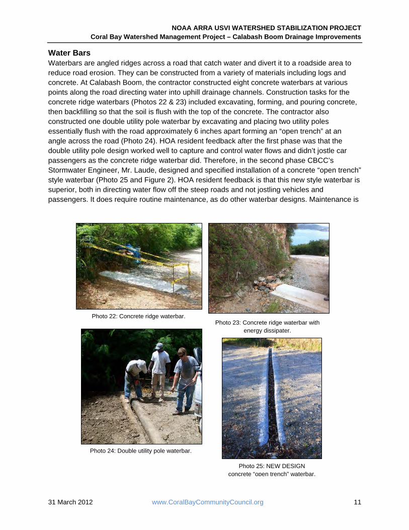
Photo 24: Double utility pole waterbar.
Photo 25: NEW DESIGN concrete “open trench” waterbar.
Photo 22: Concrete ridge waterbar.Photo 23: Concrete ridge waterbar with
energy dissipater.
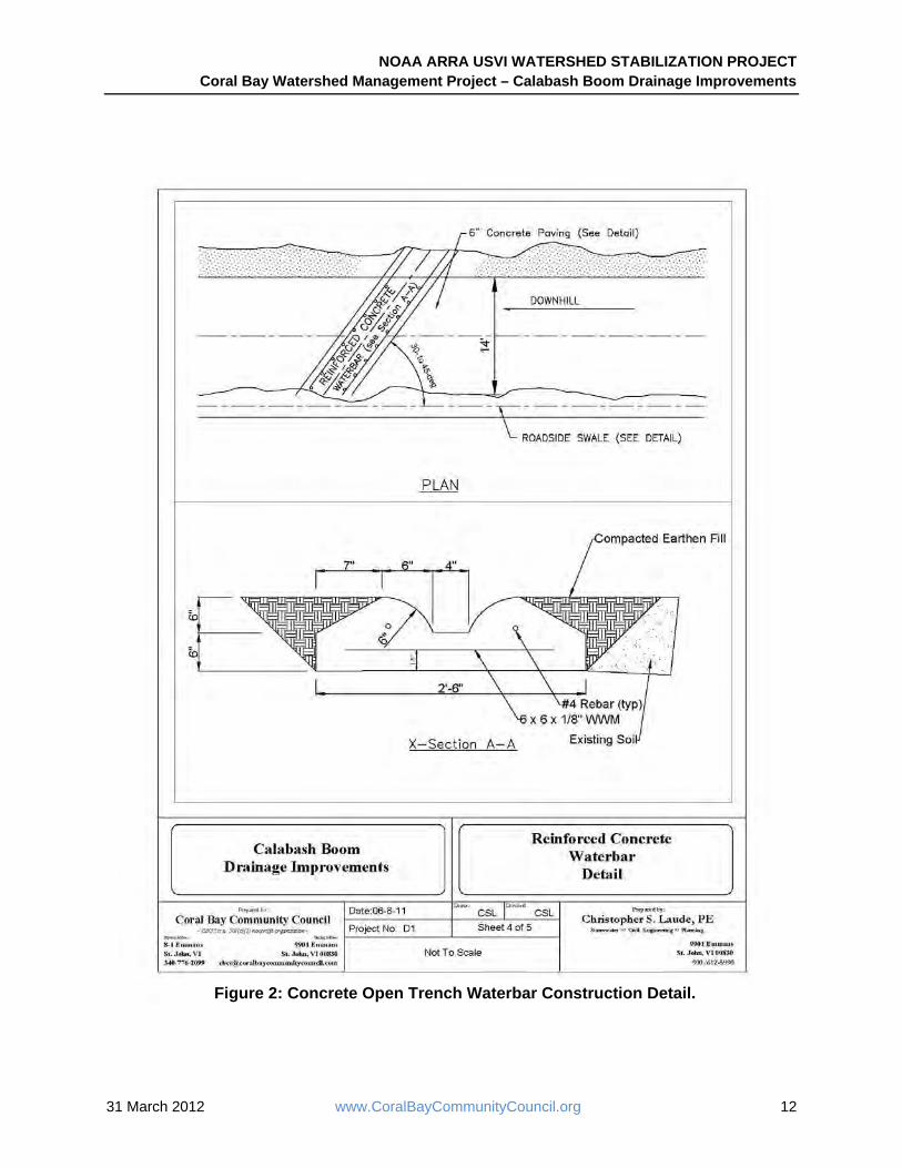
Water Bars Waterbars are angled ridges across a road that catch water and divert it to a roadside area to reduce road erosion. They can be constructed from a variety of materials including logs and concrete. At Calabash Boom, the contractor constructed eight concrete waterbars at various points along the road directing water into uphill drainage channels. Construction tasks for the concrete ridge waterbars (Photos 22 & 23) included excavating, forming, and pouring concrete, then backfilling so that the soil is flush with the top of the concrete. The contractor also constructed one double utility pole waterbar by excavating and placing two utility poles essentially flush with the road approximately 6 inches apart forming an “open trench” at an angle across the road (Photo 24). HOA resident feedback after the first phase was that the double utility pole design worked well to capture and control water flows and didn’t jostle car passengers as the concrete ridge waterbar did. Therefore, in the second phase CBCC’s Stormwater Engineer, Mr. Laude, designed and specified installation of a concrete “open trench” style waterbar (Photo 25 and Figure 2). HOA resident feedback is that this new style waterbar is superior, both in directing water flow off the steep roads and not jostling vehicles and passengers. It does require routine maintenance, as do other waterbar designs. Maintenance is
NOAA ARRA USVI WATERSHED STABILIZATION PROJECT Coral Bay Watershed Management Project – Calabash Boom Drainage Improvements
31 March 2012 www.CoralBayCommunityCouncil.org 12
Figure 2: Concrete Open Trench Waterbar Construction Detail.

NOAA ARRA USVI WATERSHED STABILIZATION PROJECT Coral Bay Watershed Management Project – Calabash Boom Drainage Improvements
31 March 2012 www.CoralBayCommunityCouncil.org 13
less important if the bar is angled near 35 degrees downhill and if there is a dropoff into the roadside drainage area, so that accumulation of sediment is less likely in the waterbar structure itself. According to Mr. Laude, it is very important that waterbars be set at a 25 to 35 degree angle on the road, rather than perpendicular, or directly across, the road surface. This allows the water flow to be turned and directed off the road surface, while still retaining sufficient velocity to carry debris off the road surface. If the waterbar is placed directly across the road, water hits the bar, drops its large debris in a pile, and maintenance (removing dirt and rocks) must be done much more frequently to keep the water flowing off the road, rather than jumping the waterbar and continuing down the road surface.
Roadside Drainage Where possible, engineers design roadside drainage to keep water off a road and funnel it to constructed drainage structures or natural waterways. For Calabash Boom Road, the contractor cleaned/excavated about 580 linear feet (LF) of roadside ditching (Photo 26) in two separate areas - before the first switchback (260 LF) and after the second switchback (320 LF). This ditching included the step pools and rock check dams discussed in the next section.
Step Pools and Rock Check Dams Step pools and check dams are structures constructed across a channel to slow water velocities and reduce erosion. They also capture sediment as water passes through the structure. Rock check dams are best in flatter road sections and step pools in steeper areas (Kitchell and Claytor 2009). For Calabash Boom, the contractor:
1. Installed six step pools (Photo 27) in roadside drainage channels from the first switch back through the second switchback and one additional larger step pool in an area above the third switchback.
2. Backfilled the existing roadside ditch with minimum 1-foot diameter rock riprap to create rock check dams.
HOA representatives say the step pools and check dams work very well in trapping sediment. The HOA pays a maintenance worker to remove the sediment routinely from the step pools.
4.5 Achieved Results Stormwater BMPs in the upper watershed now direct water flows off the road frequently, which helps reduce road erosion. Also, in several places stormwater is conveyed through step pools/check
Photo 26: Roadside drainage channel.
Photo 27: Step Pool.

NOAA ARRA USVI WATERSHED STABILIZATION PROJECT Coral Bay Watershed Management Project – Calabash Boom Drainage Improvements
31 March 2012 www.CoralBayCommunityCouncil.org 14
dams slowing velocities allowing sediment to settle out of solution, cleaning stormwater runoff prior to delivering the stormwater to natural ghut areas. After the stormwater flows into the ghut, it has time to infiltrate or receive natural ghut cleansing before arriving at the lower watershed. This has led to less water on the roads and less-turbid water in the lower watershed. For a total project cost of $185,926, CBCC was able to reduce roadway erosion; thus reducing sediment eventually discharged into Johnson Bay and at Shipwreck Landing. Attachment A is an interpretive poster that highlights these achievements.
5. Sediment Reduction Monitoring Researchers conducted sediment and turbidity monitoring at sites within the Calabash Boom Drainage Basin and below the basin in Coral Bay. Dr. Barry Devine led a monitoring team that tracked turbidity in the watershed over a two-year period (September 2009 through September 2011). Dr. Devine used three primary sampling points in the Calabash Boom Drainage Basin for turbidity monitoring: (1) Shipwreck Ghut Outlet sampling occurred where ghut flows entered Johnson Bay; (2) the Calabash Outlet sampling point captured turbidity measurements after emptying from the Calabash Boom Housing Complex’s detention basin as the runoff crossed a Route 107 swale; and (3) the Johnson Bay Shoreline sampling point at the Calabash Boom Ghut outlet downstream from the Calabash Outlet sampling point after the runoff had flowed through a short stretch of shoreline property. After analyzing the data, Dr. Devine’s results (partially NOAA ARRA funded) showed:
“The Calabash [Boom] [W]atershed drainage system was re-channeled from the roadways back into the natural ghuts and swales thereby increasing the capacity of the system to contain and slowly [release] the drainage flow, trapping the sediment naturally in the deep ghuts. [Results] show a significant decrease in the record of turbidity [as a consequence of little to] no flow. This can be partially explained by seasonal lack of rainfall but the precipitous drop in the turbidity events is also indicative of [less storm flows] reaching the bay from the huge natural ghut storage” (Devine 2012).
Additionally, after project construction, the monitoring team began to collect a series of samples from the upper roadside drainage channel to analyze how well the stormwater BMPs were reducing sediment as the water flowed off the road and through a series of step pools and check dams. This data showed that by the third sampling point right before stormwater enters Shipwreck Ghut there is a definite drop in turbidity (i.e. 195.33 NTUs uphill at Sample Site #2 versus 43.8 NTUs downhill at Sample Site #3) (CBCC 2012).
Dr. Sarah Gray, University of San Diego, and her team (partially NOAA ARRA funded) conducted marine and terrestrial sediment and water quality monitoring in Coral Bay from July 2007 to early March 2012. Her team regularly monitored 25 sediment traps at 14 stations in four bays (Great Lameshur, Little Lameshur, Coral Bay, and Hurricane Hole), collecting water and sediment samples at regular intervals (approximately every 26-28 days) at two trap heights (30 & 60 cm from bottom) and when storms occurred. Dr. Gray selected 11 main sites throughout Coral Bay including three in Hurricane Hole to capture sediment coming off an undisturbed watershed, two offshore reef areas, and the other six sites were along the developed Coral Bay

NOAA ARRA USVI WATERSHED STABILIZATION PROJECT Coral Bay Watershed Management Project – Calabash Boom Drainage Improvements
31 March 2012 www.CoralBayCommunityCouncil.org 15
shoreline. The Calabash Shore (TC-1) and Shipwreck Shore (TC-3) sites were located at the base of ghut outlet. Her results showed:
“Total and terrigenous sediment accumulation was generally higher below the steepest and most developed watersheds (such as Shipwreck [TC-3B] and Coral Harbor [TC-5, TC-8]) than below the [less] developed watersheds (such as Plantation Hill) for equivalent environments. … Additionally, total sediment trap accumulation rates were highest at the Shipwreck shore site, which is below a developed steep watershed. … Finally, total sedimentation accumulation rates below all ARRA mitigated watersheds (North Mangrove [TC-5], South Mangrove [TC-8], Shipwreck Shore [TC-3B]) were lower during the fall of 2011, which was the post-mitigation period compared to 2010. But these 2011 accumulation rates do not appear to be measurably lower than they were pre-mitigation during the fall rainy season of 2009. Completion of our fall 2011 monitoring and a detailed analysis and comparison of terrigenous (not total accumulation) and environmental data (rainfall and currents) during specific storm periods will be required before we can make an assessment of whether there has been a measurable post-mitigation reduction in marine terrigenous accumulation based on these data” (Gray 2012).
6. Lessons Learned Better Waterbar Design: The two construction phases of this project allowed for refinement and evolution of waterbar designs, as was discussed above in Section 4. The new concrete double water bar designed by CBCC Stormwater Engineer, Mr. Laude, was judged by the residents and maintainers as being superior. Thus, this design will be recommended for future use.
Dirt road surfaces last longer after waterbars are installed: Moving water off the road surface with waterbars and into roadside drainage channels allowed the graded sections of the road to last longer because water flows are not making eroding channels down road surfaces. Obviously, this also means that less sediment has flowed downstream off the road surface during the same time period; and less frequent grading means less frequent dirt disturbance that invariably causes a high sediment incidence on a short-term basis.
Selection priorities for limited paving: Paving switchbacks to stabilize and permanently direct water flow in the most desirable directions is generally a highly beneficial BMP. The water can be directed either off the road into neighboring ghuts, if available, or directed to curve down with the paving to a preferred flow area below. Paving switchbacks should be considered a top priority. Intentionally making a determination about waterflows before any paving is also essential.
Step pools catch sediment well: The step pools do catch sediment, which must be removed at regular intervals by PW, HOAs, or neighboring residents. This sediment can be useful topsoil.
Contractor bidding practices: The project partners realized early on that the best strategy was to bid out a longer list than we expected to be able to fund, review the bids, and then choose the

NOAA ARRA USVI WATERSHED STABILIZATION PROJECT Coral Bay Watershed Management Project – Calabash Boom Drainage Improvements
31 March 2012 www.CoralBayCommunityCouncil.org 16
elements that created the most cost-effective mix of BMPs. For the Calabash Boom Draiange Basin Project Phase 1, there was a bid from one of the usual PW road bidders - which was more than double the local contractors’ bids. Subsequently, none of the several road companies would respond to our bid requests, and as we became better educated we realized that the premium received by territory-wide road project contractors is high. There may be some justifiable reasons, such as slow pay and difficult competitive bid processes, but some of this premium may be due to lack of competition. Since construction material and labor costs are so high in the Virgin Islands, anything that can possibly be done to reduce the cost of PW contracting in the future would increase the total amount of paving and stormwater device structures that could be built.
7. Next Steps Any time additional funding is available from any source; more work could be done to pave and add more stormwater BMPs to the Calabash Boom Road. In the Virgin Islands’ current economic condition, it is unlikely that public funds will be available soon for improving this secondary road.
The Shipwreck Ghut outflow to Coral Bay continues to be a source of sedimentation. The use of a hydrodynamic separator or some other “last chance” device to cleanse stormwater entering the bay continues to be needed. The barriers to implementing this device and other work in this ghut channel (see above) remain a challenge.
8. References Coral Bay Community Council (CBCC). 2012. EPA CARE Grant Final Report. Turbidity Report. Devine, Barry, Ph.D. 2012. Virgin Islands NOAA-ARRA Monitoring Program Pre- and Post- Treatment Turbidity Monitoring Report Coral Bay Watershed. Devine, B., Brooks, G., and R. Nemeth. 2003. Coral Bay Sediment Deposition and Reef Assessment Study. State of the Bay, Final Project Report, Executive Summary. Submitted to VI DPNR Division of Environmental Protection MOA #NPS-01801. Gray, Sarah, Ph.D. 2012. Effects of Watershed Erosion Control on Land-Based Sources of Pollution to Coral Reefs in RCP Priority Site. January 30.2012. Kitchell, Anne and Rich Claytor. 2009. Memorandum to Danielle Lucid, NOAA and Sharon Coldren, Coral Bay Community Council. Re: Summary of Calabash Boom Road Improvements Options. Horsley Witten Group. November 11, 2009.

Attachment A: Watershed Poster
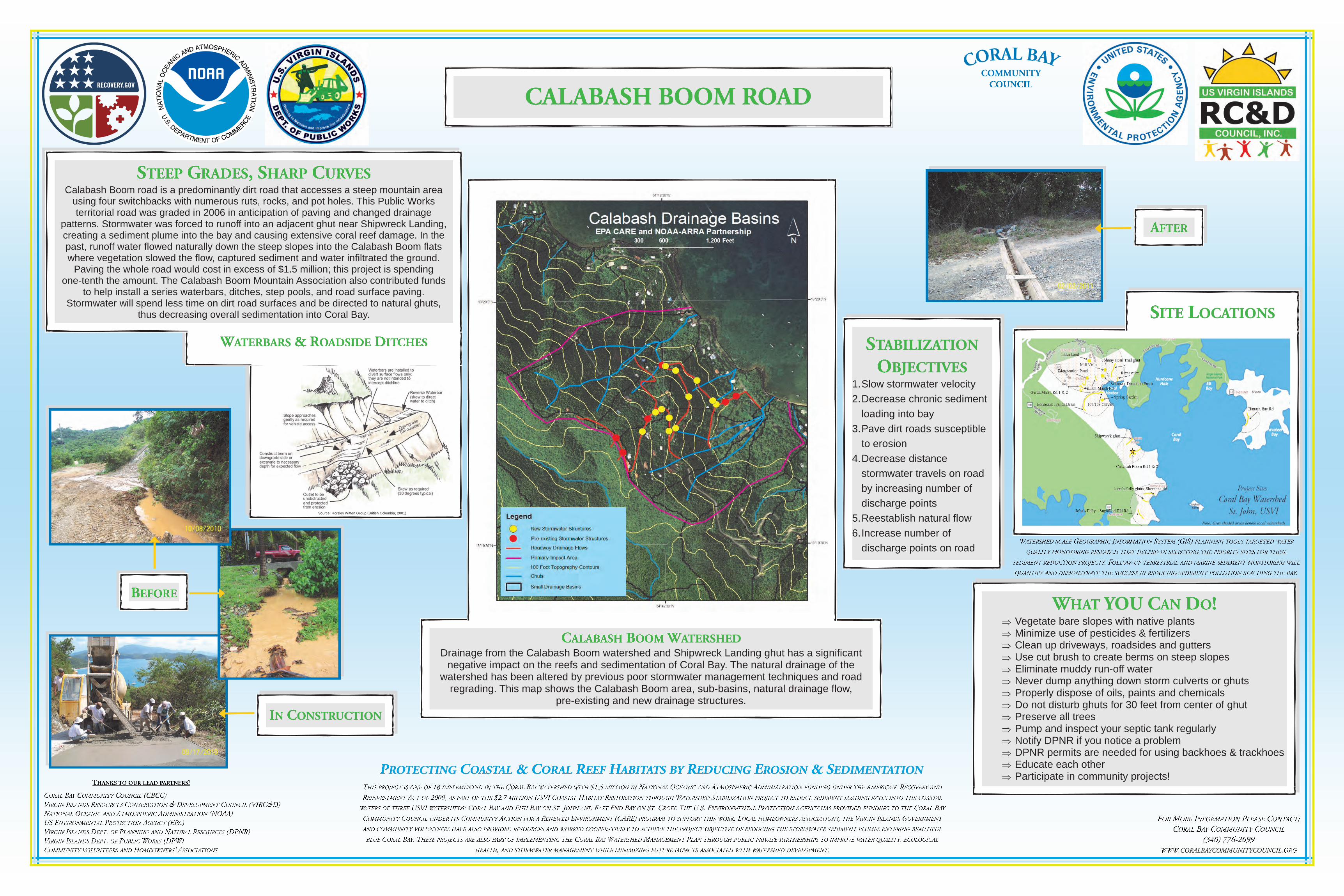
Vegetate bare slopes with native plants Minimize use of pesticides & fertilizers Clean up driveways, roadsides and gutters Use cut brush to create berms on steep slopes Eliminate muddy run-off water Never dump anything down storm culverts or ghuts Properly dispose of oils, paints and chemicals Do not disturb ghuts for 30 feet from center of ghut Preserve all trees Pump and inspect your septic tank regularly Notify DPNR if you notice a problem DPNR permits are needed for using backhoes & trackhoes Educate each other Participate in community projects!
1. Slow stormwater velocity 2. Decrease chronic sediment
loading into bay 3. Pave dirt roads susceptible
to erosion 4. Decrease distance
stormwater travels on road by increasing number of discharge points
5. Reestablish natural flow 6. Increase number of
discharge points on road
Drainage from the Calabash Boom watershed and Shipwreck Landing ghut has a significant
negative impact on the reefs and sedimentation of Coral Bay. The natural drainage of the watershed has been altered by previous poor stormwater management techniques and road
regrading. This map shows the Calabash Boom area, sub-basins, natural drainage flow, pre-existing and new drainage structures.
Calabash Boom road is a predominantly dirt road that accesses a steep mountain area using four switchbacks with numerous ruts, rocks, and pot holes. This Public Works territorial road was graded in 2006 in anticipation of paving and changed drainage
patterns. Stormwater was forced to runoff into an adjacent ghut near Shipwreck Landing, creating a sediment plume into the bay and causing extensive coral reef damage. In the past, runoff water flowed naturally down the steep slopes into the Calabash Boom flats where vegetation slowed the flow, captured sediment and water infiltrated the ground.
Paving the whole road would cost in excess of $1.5 million; this project is spending one-tenth the amount. The Calabash Boom Mountain Association also contributed funds
to help install a series waterbars, ditches, step pools, and road surface paving. Stormwater will spend less time on dirt road surfaces and be directed to natural ghuts,
thus decreasing overall sedimentation into Coral Bay.
Source: Horsley Witten Group (British Columbia, 2001)
Note: Gray shaded areas denote local watersheds

Appendix A: Engineering Designs & Drawings

CORAL BAY COMMUNITY COUNCIL, INC. Mailing: 9901 Estate Emmaus, St. John, VI 00830
Office: 8-1 Estate Emmaus, Coral Bay, St. John, U.S. Virgin Islands E-mail: [email protected] Phone/Fax: 340-776-2099
Coral Bay Projects Design Guidance
Strategies Appropriate for Coral Bay Environment
By: Joseph Mina, P.E.
1. Many natural drainage flows have been disturbed by construction and other man-made activities. A primary method of addressing water quality exiting the watershed into the bay will be to restore natural drainage flow patterns to the greatest extent possible both in intermittent drainage swales and ghuts and restoring sheet flow over steep slopes where possible. This will be accomplished primarily by:
a. Redirecting drainage from channels and redirecting the large areas of upslope water intercepted along many roads and construction sites and distribute that water using level spreaders, bioretention/infiltration devices and/or rock aprons or similar means to recreate the natural sheet flow, reduce velocity and improved percolation into soil.
i. Regrade roadbeds to direct flows to appropriate outflow devices where feasible, and add additional paving or permanent structures as appropriate to make preferred patterns of flow permanent.
ii. Add shallow vegetated swales, and detention areas with rocks and naturalized vegetation where possible to reduce velocity and promote infiltration.
iii. Install trench drains across driveways and roads into rain gardens, infiltration trenches, localized water collection systems for irrigation, or other appropriate devices.
b. Eliminate deep excavated unlined ditches which are common to many of the dirt roads in order to slow velocities and reduce amount of sediment produced by erosion. Check dams, bioretention swales, and underground stone trenches with perforated pipe will be installed where appropriate.
c. Reduce the length water travels in roadside swales by directing flow from roadways into devices often. Preferably at each switchback at a minimum by incorporating drywells, rain gardens and infiltration chambers using locally available materials and native species.
2. Retain and slow down water that reaches valley floor in larger scale regional detention/retention basins with Best Management Practices installed including forebays, infiltration cells and bioretention pond areas:
a. Devices will utilize native plantings and species where possible and available to mimic local Caribbean seasonal flow dry ghut conditions to promote both stormwater quality and to provide wildlife and riparian habitat restoration.
b. Sediment deposition retention area, cleaned regularly, with reuse of sediment material as gravel, topsoil, building sand, etc.

3. Provide “Last Chance” effort to reduce sediment entering sea at ends of ghuts and drainage ways immediately adjacent to where the flows enter the ocean.
a. Install devices just upstream of exit to the ocean from ghuts including:
i. Combination of weirs, pre-manufactured sediment retention chambers and/or small bioretention areas with local rock rip-rap aprons and multi-step natural rock retention step pools.
ii. Baffles and check dams where ghut is large enough.
iii. Construct and maintain natural “Caribbean Berm” (usually created by wave action and sand deposition) where water enters ocean in each area to provide natural sediment protection. Protection against mosquitoes and parasites in sitting water with guppies)
b. Slow, redirect and/or restore gut flow within 300 yards of ocean by installing the following where appropriate and feasible:
i. Re-vegetate gut outflow areas.
ii. Rock weirs, ghut slope and embankment protection including erosion control blankets, concrete cable mats or other manufactured devices to reduce erosion.
c. Install in-line biofiltration areas and flow spreading devices to slow velocities and provide opportunities for sediment to drop out and naturalized vegetation to reduce pollutant loading in the runoff.
4. Correction of failed devices, culverts, water routing by installing any appropriate Best Management Practices to attempt to solve some past poor choices of storm water management, or areas where no thought was given to management.
June 2009

CORAL BAY COMMUNITY COUNCIL, INC. Mailing: 9901 Estate Emmaus, St. John, VI 00830 E-mail: [email protected] Office: 8-1 Estate Emmaus, Coral Bay, St. John, U.S. Virgin Islands Phone/Fax: 340-776-2099
Engineering Recommendation Memo A Series of Observations & Preliminary Recommendations
- CBCC is a 501(c)(3) nonprofit organization - EPA Environmental Quality Award Winner – 2007
Page 1 of 5
CBCC Engineering Recommendation Memo #2
From: Joseph A. Mina, P.E. Date: May 13, 2009
Subject Property: Coral Bay
Specific Issue: Plumes of Sediment Laden Runoff in Multiple Locations – Johnson Bay Area Reliance and Shipwreck Ghut.
There are four primary areas where plumes of sediment laden water flow into the bay as a result of improper erosion and sediment pollution control in the various watersheds. These are Johnson Bay, Coral Bay at Voyages, Coral Bay at Kings Hill Road, and The Creek behind Skinny Legs. Due to the large amount of photos, these four areas will be the subject of the next four Engineering Recommendation Memos. The summary paragraphs below will be repeated for ease of reference. Summary On May 4, 2009 there was a substantial rainfall event that, according to various sources, dropped between 10 to 12 inches of rain on Cruz Bay. By my observations of the storm event’s intensities in both Coral Bay and Cruz Bay, I estimate that between 8 and 10 inches fell in Coral Bay. During the event, I performed numerous site visits and took many photos.
It should be noted that in general, during an event of this magnitude, it is almost impossible to manage the runoff, and most BMP’s seek to control the first 1” to 1.5” of runoff from a drainage area, or the 3” rain event. While I am still making a decision on which rain event to choose for our future BMP designs, I do know the devices will not manage this type of storm but only serve to pass larger events through safely after controlling the first 1” to 1.5” of runoff. It also needs to be noted that my estimates are prevalent throughout the memo. These are based on my personal observations of the intensities and reports from others describing the type of rain falling. At this time, there is no scientific measurement of these amounts, just a “best guess” based on professional experience.
During the early portion of my observations (prior to 8AM) few of the ghuts were actually flowing, and much of the runoff observed watershed-wide was clearly the result of impervious surfaces, construction activities, or runoff from existing roadways that acted as channels and decreased the initial runoff Times of Concentration. The Ghuts began to run between 8:30 and 10AM depending on the upstream watershed characteristics. This supports my “first flush” theory that the initial 1.5” of runoff is clearly the real culprit in the spiking amounts of sediment laden waters entering the bay.
Johnson Bay Plumes There are two plumes discharging into Johnson Bay. One is a result of the Ghut adjacent to Shipwreck’s Landing (Shipwreck Ghut) and the other is a result of a watercourse/ghut that is on a portion of land that is currently under construction for the Reliance Housing Project. Each of these areas has some specific concerns and potential solutions.

CORAL BAY COMMUNITY COUNCIL, INC. Mailing: 9901 Estate Emmaus, St. John, VI 00830 E-mail: [email protected] Office: 8-1 Estate Emmaus, Coral Bay, St. John, U.S. Virgin Islands Phone/Fax: 340-776-2099
Engineering Recommendation Memo A Series of Observations & Preliminary Recommendations
- CBCC is a 501(c)(3) nonprofit organization - EPA Environmental Quality Award Winner – 2007
Page 2 of 5
Shipwreck Ghut Plume Close Up of Shipwreck Ghut Plume Reliance Area Plume

CORAL BAY COMMUNITY COUNCIL, INC. Mailing: 9901 Estate Emmaus, St. John, VI 00830 E-mail: [email protected] Office: 8-1 Estate Emmaus, Coral Bay, St. John, U.S. Virgin Islands Phone/Fax: 340-776-2099
Engineering Recommendation Memo A Series of Observations & Preliminary Recommendations
- CBCC is a 501(c)(3) nonprofit organization - EPA Environmental Quality Award Winner – 2007
Page 3 of 5
1. Shipwreck Ghut Plume This Plume emanates from a ghut adjacent to Shipwreck Landing that has a fairly large watershed contributing.
However, during my initial observations (before 8AM) the only runoff entering the bay was clearly from the roadway (Rt. 107) and various construction projects in the lowest portions of the watershed. The following pictures illustrate this.
Examples of Roadway Leading up to Shipwreck Ghut
Ghut Upstream of Rt. 107 Downstream of Rt. 107 Small Plume Beginning to Form
CORAL BAY COMMUNITY COUNCIL, INC. Mailing: 9901 Estate Emmaus, St. John, VI 00830 E-mail: [email protected] Office: 8-1 Estate Emmaus, Coral Bay, St. John, U.S. Virgin Islands Phone/Fax: 340-776-2099
Engineering Recommendation Memo A Series of Observations & Preliminary Recommendations
- CBCC is a 501(c)(3) nonprofit organization - EPA Environmental Quality Award Winner – 2007
Page 4 of 5
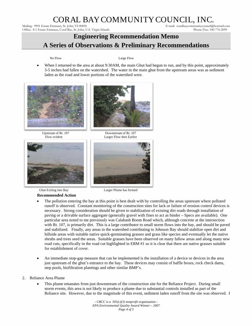
No Flow Large Flow
When I returned to the area at about 9:30AM, the main Ghut had begun to run, and by this point, approximately 3-5 inches had fallen on the watershed. The water in the main ghut from the upstream areas was as sediment laden as the road and lower portions of the watershed were.
Upstream of Rt. 107 Downstream of Rt. 107 Flow evident Larger Flow then Earlier
Ghut Exiting into Bay Larger Plume has formed
Recommended Action
The pollution entering the bay at this point is best dealt with by controlling the areas upstream where polluted runoff is observed. Constant monitoring of the construction sites for lack or failure of erosion control devices is necessary. Strong consideration should be given to stabilization of existing dirt roads through installation of paving or a drivable surface aggregate (generally gravel with fines to act as binder – Specs are available). One particular area noted to me previously was Calabash Boom Road which, although concrete at the intersection with Rt. 107, is primarily dirt. This is a large contributor to small storm flows into the bay, and should be paved and stabilized. Finally, any areas in the watershed contributing to Johnson Bay should stabilize open dirt and hillside areas with suitable native quick-germinating grasses and grass like species and eventually let the native shrubs and trees seed the areas. Suitable grasses have been observed on many fallow areas and along many new road cuts, specifically in the road cut highlighted in ERM #1 so it is clear that there are native grasses suitable for establishment of cover.
An immediate stop-gap measure that can be implemented is the installation of a device or devices in the area just upstream of the ghut’s entrance to the bay. These devices may consist of baffle boxes, rock check dams, step pools, biofiltration plantings and other similar BMP’s.
2. Reliance Area Plume
This plume emanates from just downstream of the construction site for the Reliance Project. During small storm events, this area is not likely to produce a plume due to substantial controls installed as part of the Reliance site. However, due to the magnitude of this event, sediment laden runoff from the site was observed. I
CORAL BAY COMMUNITY COUNCIL, INC. Mailing: 9901 Estate Emmaus, St. John, VI 00830 E-mail: [email protected] Office: 8-1 Estate Emmaus, Coral Bay, St. John, U.S. Virgin Islands Phone/Fax: 340-776-2099
Engineering Recommendation Memo A Series of Observations & Preliminary Recommendations
- CBCC is a 501(c)(3) nonprofit organization - EPA Environmental Quality Award Winner – 2007
Page 5 of 5
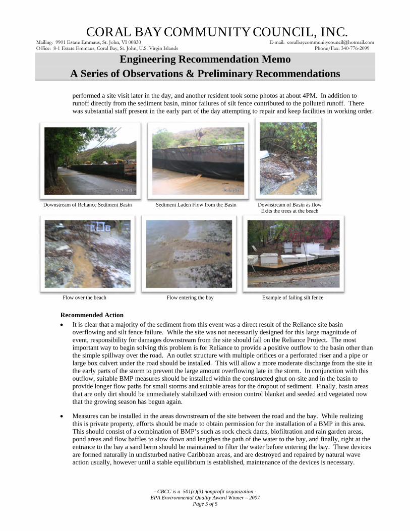
performed a site visit later in the day, and another resident took some photos at about 4PM. In addition to runoff directly from the sediment basin, minor failures of silt fence contributed to the polluted runoff. There was substantial staff present in the early part of the day attempting to repair and keep facilities in working order.
Downstream of Reliance Sediment Basin Sediment Laden Flow from the Basin Downstream of Basin as flow Exits the trees at the beach
Flow over the beach Flow entering the bay Example of failing silt fence
Recommended Action
It is clear that a majority of the sediment from this event was a direct result of the Reliance site basin overflowing and silt fence failure. While the site was not necessarily designed for this large magnitude of event, responsibility for damages downstream from the site should fall on the Reliance Project. The most important way to begin solving this problem is for Reliance to provide a positive outflow to the basin other than the simple spillway over the road. An outlet structure with multiple orifices or a perforated riser and a pipe or large box culvert under the road should be installed. This will allow a more moderate discharge from the site in the early parts of the storm to prevent the large amount overflowing late in the storm. In conjunction with this outflow, suitable BMP measures should be installed within the constructed ghut on-site and in the basin to provide longer flow paths for small storms and suitable areas for the dropout of sediment. Finally, basin areas that are only dirt should be immediately stabilized with erosion control blanket and seeded and vegetated now that the growing season has begun again.
Measures can be installed in the areas downstream of the site between the road and the bay. While realizing this is private property, efforts should be made to obtain permission for the installation of a BMP in this area. This should consist of a combination of BMP’s such as rock check dams, biofiltration and rain garden areas, pond areas and flow baffles to slow down and lengthen the path of the water to the bay, and finally, right at the entrance to the bay a sand berm should be maintained to filter the water before entering the bay. These devices are formed naturally in undisturbed native Caribbean areas, and are destroyed and repaired by natural wave action usually, however until a stable equilibrium is established, maintenance of the devices is necessary.

CORAL BAY COMMUNITY COUNCIL, INC. Mailing: 9901 Estate Emmaus, St. John, VI 00830 E-mail: [email protected] Office: 8-1 Estate Emmaus, Coral Bay, St. John, U.S. Virgin Islands Phone/Fax: 340-776-2099
Engineering Design Recommendation Memo
- CBCC is a 501(c)(3) nonprofit organization -
EPA Environmental Quality Award Winner – 2007
Page 1 of 6
From: Joseph A. Mina, P.E. Date: February 8, 2010
Subject Property: Calabash Boom Road
Specific Issue: Detailed Recommendations for Road Grading, Waterbars and Roadway Drainage Improvements
Project No: D-01
Attachments: Roadway Improvement Locations & Drainage Area Map
This memo is the detailed design of roadway improvements recommended in a Memo dated November 11, 2010 by the
Horsley Whitten Group for the Calabash Boom Road. The Horsley Whitten recommendations were modified slightly based
on a subsequent site walk with a potential contractor and further analysis of hydraulic and hydrologic calculations performed.
Estimates for flow are included herein and a detailed mapping and description of improvements are included in this memo.
Design Considerations & Methods of Analysis • Two Points of Interest were analyzed
o POI A - Areas flowing to the ghut that discharges across Rt. 107 just below the Calabash Boom Housing
Project. This flow enters the ghut before the top of the development.
o POI B - Areas flowing to the ghut adjacent to Bonny’s house that eventually flow into the ghut adjacent to
Shipwreck Landing and discharges to the ocean at that point.
• 7 Drainage areas contributing to the roadway flows were analyzed. A Site Location Map is included with this memo.
o Drainage Area #1 consists of the area tributary to a location that discharges to the roadside swale located at the
end of the paved concrete portion of the road coming up the hill from Rt. 107 that continues into Drainage Area
#7 along an unused portion of Calabash Boom road and into POI A.
o Drainage Area #2 consists of the area tributary to the roadside swale that discharges to POI B.
o Drainage Area #3 consists of the area tributary to a proposed pipe arch structure that will discharge at Bob’s
driveway across public land and into Drainage Area #1.
o Drainage Area #4 consists of the area tributary to the roadside swale that discharges to a pipe running under a
subdivision road adjacent to Elliot’s House running into Elliot’s existing concrete step pools which eventually
flow into POI A.
o Drainage Area #5 consists of the area tributary to an existing headwall and pipe under Bruzzio’s driveway
discharging to the upper portions of the ghut that eventually makes it’s way overland to POI B.
o Drainage Area #6 consists of the area tributary to the ghut that flows to POI A that is not intercepted by any
roadway.
o Drainage Area #7 consists of the unused portion of Calabash Boom Road just above the Housing Project that
combines with flows out of Drainage Area #6 and flows to POI A.
• Flow estimates were completed using the Rational Method, and using IDF data from the NOAA Atlas 14. The 50 year
storm intensity of 10.08 in/hr from these IDF curves was used as the base for the model, and an analysis.
• Times of Concentration were generally assumed to be 5 minutes to maintain a conservative estimate of flows, and due to
the extreme steep slopes and quickly travelling water along the roadway in this watershed.
• The cover condition ‘C’ value was estimated based on aerial photographs, and calculated as show in the tables in this
Memo.
• Culvert calculations for the Pipe Arch were completed using the FHWA HY-8 Program to analyze performance.
• Data on topography and elevation was taken from existing GIS models and site reconnaissance.
• Any recommendations in this memo that are implemented should be field adjusted to match the exact conditions found
during installation.

CORAL BAY COMMUNITY COUNCIL, INC. Mailing: 9901 Estate Emmaus, St. John, VI 00830 E-mail: [email protected] Office: 8-1 Estate Emmaus, Coral Bay, St. John, U.S. Virgin Islands Phone/Fax: 340-776-2099
Engineering Design Recommendation Memo
- CBCC is a 501(c)(3) nonprofit organization -
EPA Environmental Quality Award Winner – 2007
Page 2 of 6
Areas, ‘C’ values & Flow Calculations Flow Summary Table
POI DA #
Total
Area
(A)
Area
Impervious
(C=0.9)
Area
Wooded
(C=0.2)
Area
Road
(C=0.8)
Avg
C
100YR
(i) Q
*
Q out of DA
(Upstream
DAs added)
(ac) (ac) (ac) (ac)
(in/hr) (cfs)
A 1 2.56 0.1 2.16 0.3 0.30 10.08 7.7
B 2 3.43 0.1 3.02 0.4 0.30 10.08 10.2 21.5
A 3 0.9 0.1 0.65 0.15 0.38 10.08 3.4
A 4 2.64 0.2 2.18 0.35 0.34 10.08 9.0 9.0
B 5 3.91 0.2 3.51 0.3 0.29 10.08 11.3
A 6 9.25 0.5 8.45 0.3 0.26 10.08 24.0 53.5
A 7 3.78 0.1 3.51 0.17 0.25 10.08 9.4 20.5
*Rational Method Q=CiA (Using Avg C)
** Pre-Improvement Condition DA 3 flows to POI B. Post re-directs it to POI A. POI A Pre-Total 50.1
POI A Post Total 53.5
POI B Pre Total 25.0
POI B Post Total 21.5
“No Harm” Analysis The redirection of 3.4 cfs from POI B to POI A necessitates an analysis to ensure that no harm will come to the downstream
recipient of the water. In this case, it is the ghut constructed in the Calabash Boom Housing Project.
Based on a visual inspection of the site, the swale is approximately trapezoidal with an approximate 5’ wide bottom and 3:1
sideslopes. Slopes and depths vary, but in general depths are a minimum of 4’ to 5’and slope is a minimum of 5% where the
flow enters the site. The flow into POI A in both Pre & Post conditions is shown in the above table.
Based on this the following calculations show that there is no significant increase in depths of flow within the channel, and
that no harm will come to the downstream areas. Both Pre and Post conditions have a depth of approximately 0.6 ft in a
channel that is 4’ or more in depth.

CORAL BAY COMMUNITY COUNCIL, INC. Mailing: 9901 Estate Emmaus, St. John, VI 00830 E-mail: [email protected] Office: 8-1 Estate Emmaus, Coral Bay, St. John, U.S. Virgin Islands Phone/Fax: 340-776-2099
Engineering Design Recommendation Memo
- CBCC is a 501(c)(3) nonprofit organization -
EPA Environmental Quality Award Winner – 2007
Page 3 of 6
Pre-Improvement Channel Post-Improvement Channel
Roadside Swale Design • Based on the flows calculated above, the maximum flow in a roadside swale is 11.3cfs. A value of 12cfs was used to
develop the swale sizing.
• Slopes on the road vary from 20% to 1%. Sizing for velocity protection was done using the 20% condition, and depth
was sized using the 1% condition.
• Based on the velocities, minimum 4-6” stone should be placed in the bottom of all roadside swales that are steeper than
20% unless the swale is cut directly into bedrock or has significant existing rock in the bottom.
• Channel Dimensions should be trapezoidal with a 2:1 side slope and a 1’ bottom width, and a minimum of 18” in depth.
• Telephone pole waterbars should be placed every 50’ to 75’ along the roadway and at significant grade breaks in the road
to direct flows into the roadside swales except where future paving is anticipated. (Refer to plans for more details)
• Step pools and plunge pools should be included regularly in the roadside swales to create areas for sediment deposition.
These areas should be cleaned out as they fill up, and maintained on a regular basis to ensure performance.

CORAL BAY COMMUNITY COUNCIL, INC. Mailing: 9901 Estate Emmaus, St. John, VI 00830 E-mail: [email protected] Office: 8-1 Estate Emmaus, Coral Bay, St. John, U.S. Virgin Islands Phone/Fax: 340-776-2099
Engineering Design Recommendation Memo
- CBCC is a 501(c)(3) nonprofit organization -
EPA Environmental Quality Award Winner – 2007
Page 4 of 6
1% - Channel Sizing Analysis – shows 15” flow 20% Velocity Analysis – Shows need for 4 to 6” rock lining
CORAL BAY COMMUNITY COUNCIL, INC. Mailing: 9901 Estate Emmaus, St. John, VI 00830 E-mail: [email protected] Office: 8-1 Estate Emmaus, Coral Bay, St. John, U.S. Virgin Islands Phone/Fax: 340-776-2099
Engineering Design Recommendation Memo
- CBCC is a 501(c)(3) nonprofit organization -
EPA Environmental Quality Award Winner – 2007
Page 5 of 6
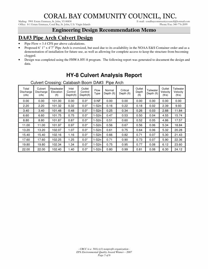
DA#3 Pipe Arch Culvert Design • Pipe Flow = 3.4 CFS per above calculations.
• Proposed 6’ 1” x 4’7” Pipe Arch is oversized, but used due to its availability in the NOAA E&S Container order and as a
demonstration of installation for future use, as well as allowing for complete access to keep the structure from becoming
clogged.
• Design was completed using the FHWA HY-8 program. The following report was generated to document the design and
data.
HY-8 Culvert Analysis Report
Culvert Crossing: Calabash Boom DA#3 Pipe Arch
Total Discharge
(cfs)
Culvert Discharge
(cfs)
Headwater Elevation
(ft)
Inlet Control
Depth(ft)
Outlet Control
Depth(ft)
Flow Type
Normal Depth (ft)
Critical Depth (ft)
Outlet Depth
(ft)
Tailwater Depth (ft)
Outlet Velocity
(ft/s)
Tailwater Velocity
(ft/s)
0.00 0.00 101.00 0.00 0.0* 0-NF 0.00 0.00 0.00 0.00 0.00 0.00 2.20 2.20 101.32 0.32 0.0* 1-S2n 0.16 0.22 0.18 0.02 2.39 9.93 3.40 3.40 101.48 0.48 0.0* 1-S2n 0.25 0.34 0.26 0.03 2.88 11.84 6.60 6.60 101.75 0.75 0.0* 1-S2n 0.47 0.53 0.50 0.04 4.55 15.74 8.80 8.80 101.87 0.87 0.0* 1-S2n 0.51 0.60 0.52 0.05 4.86 17.57
11.00 11.00 101.97 0.97 0.0* 1-S2n 0.56 0.67 0.56 0.06 5.34 18.84 13.20 13.20 102.07 1.07 0.0* 1-S2n 0.61 0.75 0.64 0.06 5.32 20.28 15.40 15.40 102.16 1.16 0.0* 1-S2n 0.66 0.82 0.71 0.07 5.30 21.43 17.60 17.60 102.25 1.25 0.0* 1-S2n 0.71 0.90 0.73 0.07 5.90 22.36 19.80 19.80 102.34 1.34 0.0* 1-S2n 0.75 0.95 0.77 0.08 6.12 23.60 22.00 22.00 102.40 1.40 0.0* 1-S2n 0.80 0.99 0.81 0.08 6.30 24.12

CORAL BAY COMMUNITY COUNCIL, INC. Mailing: 9901 Estate Emmaus, St. John, VI 00830 E-mail: [email protected] Office: 8-1 Estate Emmaus, Coral Bay, St. John, U.S. Virgin Islands Phone/Fax: 340-776-2099
Engineering Design Recommendation Memo
- CBCC is a 501(c)(3) nonprofit organization -
EPA Environmental Quality Award Winner – 2007
Page 6 of 6
DA#1 Shira’s Driveway Design • Existing driveway concrete was poorly poured and has issues extending into the road.
• Roadside swale can flow across driveway entrance with minor improvements.
• Will need to install a 5’ concrete pad at bottom of the driveway slope and repair driveway concrete to create suitable
swale/flow conveyance.
• Roadway will remain dirt in this area.
• Flow at driveway is approximately 7.7 cfs. Used 8CFS for design.
• Swale dimensions are based on visual inspection of the site. 5’ bottom width with 20% slope up drive and 5% road
cross-slope.
• Analysis shows less than 2” of water in front of driveway during runoff events.

.0 100 200 300 400 50050
Feet
Roadway Improvement Locations &
Drainage Area Plan
Calabash Boom Road
February 5, 2010
Project No: D-001
Prepared for:
Coral Bay Community Council
Prepared by:
Joseph A. Mina, P.E.
JAM Engineering Associates LLC
Segment #5 - Culvert at Don's Driveway (5) to Top of Area.
Install Telephone Pole Waterbars at approximately
50 to 75 ft. intervals directing water into uphill side swale.
Regrade and smooth roadway and regrade/excavate swale to
dimensions shown on the details.
Install waterbar across road and across private driveway to
direct roadway flows into existing culvert under driveway.
Repair and enlarge existing waterbar at top of drainage area
where road to Castle begins indicated by blue dot.
Calabash
Boom Rd.
Route 107
Segment #4 - Elliot's Switchback (4) to Culvert at Don's Driveway (5)
Install Telephone Pole Waterbars at approximately 50 to 75 ft.
intervals directing water into uphill side swale.
Regrade and smooth roadway and regrade/excavate swale to
dimensions shown on the details.
Install waterbar, step pool, & trash rack at existing driveway culvert
indicated by red dot.
Direct all roadway flows into existing culvert under driveway
indicated by blue dot into Elliot's Step pools.
Segment #3 - Bob's Driveway (3) to Elliot's Switchback (4)
Install Telephone Pole Waterbars at approximately
50 to 75 ft.
intervals directing water into uphill side swale.
Regrade and smooth roadway and regrade/excavate
swale to dimensions shown on the details.
Install waterbar, headwall, trash rack, pipe arch culvert &
endwall across road at Bob's driveway indicated
by blue dot.
Provide reinforcement using Armorflex and A-Jacks at
pipe arch outfall.
Segment #2 - Bonny's Switchback (2) to Bob's Driveway (3)
Install Concrete Paving 6" thick per Public Works Specifications
50' below and 100' above switchback. Provide min 1/4" per ft.
slope into existing roadside channels.
Install Concrete Paving 6" thick per Public Works Specifications
over approximately 200' to 500' from Private Driveway down
steepest segment as costs allow.
Drain concrete paving into dirt roadside swales.
Install Telephone Pole Waterbars along remaining
dirt areas at approximately 50 to 75 ft. intervals directing water
into uphill side swale.
Regrade and smooth roadway and regrade/excavate
swale to dimensions shown on the details.
Install Step Pools in roadside channel where indicated by red dot.
Segment #1 - Concrete End(1) to Bonny's Switchback(2)
Install Concrete Paving 6" thick per Public Works Specifications at end of existing concrete and extending
25' uphill of existing concrete. Provide min 1/4" per ft. slope into existing roadside channels.
Install Telephone Pole Waterbars along remaining dirt areas at approximately 50 to 75 ft. intervals directing
water into uphill side swale.
Regrade and smooth roadway and regrade/excavate swale to dimensions shown on the details.
Install Step Pools in roadside channel where indicated by red dot.
Repair Shira's driveway to create 5' wide swale area.
Construct concrete paving at top of existing concrete road, and at Bonny's switchback.
DA #1
DA #4
DA #7
DA #2
DA #5
DA #6
DA #3
POI A
POI B
(1)
(4)
(3)
(2)
(5)
Joseph A. Mina, P.E.
1049-E

Scope of Work & Details
for
Calabash Boom Road Grading, Drainage & Paving Improvements
PROJECT NO. D-001-10
SITUATE IN
CORAL BAY, ST. JOHN US VIRGIN ISLANDS
March 29, 2010
REVISED: April 29, 2010
PREPARED FOR:
Coral Bay Community Council, Inc. &
Virgin Islands Resource Conservation and Development Council, Inc.
NOAA-ARRA Grant 9901 Emmaus
St. John, USVI 00830
PREPARED BY:
JAM Engineering Associates LLC Stormwater ∞ Civil Engineering ∞ Planning
Joseph A. Mina, P.E.

SCOPE OF WORK Work shall consist of completing the following tasks in accordance with the plan titled, “Roadway Improvement Locations & Drainage Area Plan, Calabash Boom Road,” dated February 8, 2010 and details in this document.
1. Regrade and smooth roadway and regrade/excavate swale to dimensions shown on the details. Provide min 1/4" per ft. cross-slope. Approximately 2,340 LF. Grade roadway to prepare base for concrete paving.
2. Install 6 Concrete Waterbars along road as marked in paint on the roadsides, directing water into uphill side swale. Install 1 Double Utility Pole Waterbar in Section #4.
3. Install 6 Step Pools in roadside channels where indicated by red dots and one additional larger step pool in area above Bruzzio’s Drive.
4. Repair Shira's driveway. (first driveway on left above existing concrete at bottom of road) Install 36” HDPE (or approved equivalent) pipe under driveway, and remove concrete scraps and debris leaving existing concrete pad (approximately 5’) in place. This item includes all materials and necessary excavation to install the pipe.
5. Install trash rack at Bruzzio's Drive culvert indicated by red dot. 6. Paving Work – Install 6” paving reinforced with wire mesh per detail in areas indicated on plan.
a. At end of existing concrete installed by Reliance (50’) extending 25' uphill of existing concrete approximately to Shira’s driveway for a total of 75’ of concrete. 14’ wide pavement, installed in two 7’ wide sections to maintain traffic flow during construction.
b. 25' below and 75' above Bonny’s switchback. 14’ wide pavement, installed in two 7’ wide sections to maintain traffic flow during construction.
c. 150’ from Private Driveway at top of Segment #2 down steepest segment towards Bonny’s switchback. 9’ wide pavement. Must maintain flow of traffic around pavement during construction in dirt section of the road.
7. Upon completion of paving and removal of forms all areas shall be graded to bring the final grade flush with the edge of concrete. Graded areas shall be stabilized with erosion control blanket and seeded with bermuda grass (98% purity) at 20lbs. per acre (or approved equivalent).
NOTES AND CONDITIONS
1. All grading and compaction of graded roadways must be performed to appropriate specifications to support concrete paving.
2. Area has been marked in spray paint showing location of most of the waterbars and step pools in a site walk. Any additional questions regarding exact location and dimensions of pools can be addressed to the VIRC&D Inspector who will be on-site for regular inspection of work.
3. Contractors shall provide a cost per linear foot for paving. Actual lengths of paving may be adjusted based on this cost and available funding.
4. Traffic Flow must be maintained in at least one lane at all times, appropriate traffic control methods will be used in accordance with all Public Works requirements.
2

5. Excess material excavated shall be removed from the site or used to fill roadside areas where scour has eroded the areas adjacent to the roadside swales and is undermining the road. All areas filled and repaired shall be protected with Erosion Control Blanket and seeded with Bermuda grass (98% purity) at 20lbs. per acre. No material other than that used for roadside repairs shall remain onsite.
6. During grading & excavation work, sufficient water will be kept onsite to ensure that exposed soil and road surfaces can be sprayed down to control dust.
7. All workmanship shall comply with VI DPW specifications and FP-2006 specifications. 8. Erosion Control Matting & anchors to be provided by VIRC&D. All other materials and
supplies including but not limited to rock, concrete, and geotextile are to be provided by the contractor.
9. In areas where waterbars are to be installed in bedrock, rock swales may be substituted for wooden telephone pole waterbars. Rock swale shall be a minimum of 3’ bottom width with a maximum of 5:1 sideslopes.
10. All grading and excavation included on this job shall include all rock and ledge removal necessary to install items as specified. No additional fees shall be charged for rock work.
11. Contractor shall be responsible for installing up to four sign posts consisting of a 4" x 4" post set 2' into the ground and extending 6' above grade at locations to be determined upon the start of construction. Signs will be provided by VIRCD and mounted on the signpost by the contractor.
12. Contractor may sequence activities as needed with the approval of the VIRC&D Inspector with the exception that the concrete paving shall be installed only after all other heavy excavation is completed on the roadway to avoid heavy equipment travel over newly poured concrete.
13. BUY AMERICAN CLAUSE: Contractors are hereby notified that they are encouraged, to the greatest extent practicable, to purchase American-made equipment and products with funding provided under this award.
14. Contractor must have a VI business license to do the type of work that is being performed. 15. Contractor must have a DUNS number. 16. All workers on the projects must legally be able to work in the VI. 17. Notify Project manager, CBCC and all abutters at least 24 hours prior to beginning work. 18. Contractor must conduct a weekly safety meeting for all on site personnel 19. Provide $ 1 million liability insurance with CBCC and VIRC&D as named insured 20. Comply with all Federal and VI, DPW and DPNR regulations and requirements.
3

Scope of Work & Details Calabash Boom Road
Grading, Drainage & Paving Improvements PROJECT NO. B001-09
2.0 PLANS & DETAILS
JAM Engineering Associates LLC Stormwater ∞ Civil Engineering ∞ Planning
4

5

6

7

8

9

Scope of Work & Details Calabash Boom Road
Grading, Drainage & Paving Improvements PROJECT NO. B001-09
APPENDIX A
SPECIFICATIONS
JAM Engineering Associates LLC Stormwater ∞ Civil Engineering ∞ Planning
10
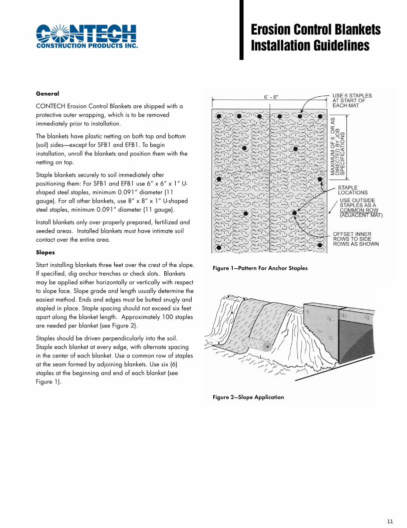
General
CONTECH Erosion Control Blankets are shipped with aprotective outer wrapping, which is to be removedimmediately prior to installation.
The blankets have plastic netting on both top and bottom(soil) sides—except for SFB1 and EFB1. To begininstallation, unroll the blankets and position them with thenetting on top.
Staple blankets securely to soil immediately afterpositioning them: For SFB1 and EFB1 use 6” x 6” x 1” U-shaped steel staples, minimum 0.091” diameter (11gauge). For all other blankets, use 8” x 8” x 1” U-shapedsteel staples, minimum 0.091” diameter (11 gauge).
Install blankets only over properly prepared, fertilized andseeded areas. Installed blankets must have intimate soilcontact over the entire area.
Slopes
Start installing blankets three feet over the crest of the slope.If specified, dig anchor trenches or check slots. Blanketsmay be applied either horizontally or vertically with respectto slope face. Slope grade and length usually determine theeasiest method. Ends and edges must be butted snugly andstapled in place. Staple spacing should not exceed six feetapart along the blanket length. Approximately 100 staplesare needed per blanket (see Figure 2).
Staples should be driven perpendicularly into the soil.Staple each blanket at every edge, with alternate spacingin the center of each blanket. Use a common row of staplesat the seam formed by adjoining blankets. Use six (6)staples at the beginning and end of each blanket (seeFigure 1).
Erosion Control BlanketsInstallation Guidelines
Figure 1—Pattern For Anchor Staples
Figure 2—Slope Application
11

Ditches or Channels
Blankets must be applied in the direction of water flow,butted snugly at ends and sides and stapled in place. Ifspecified, anchor blankets with an anchor trench at theuppermost end of channel. When using two or moreblankets side-by-side, do not place seams formed by edgesof adjoining blankets directly in the middle of the ditch invert.
Staple spacing should be four feet maximum along thelength of the blanket.
Use six (6) staples at the start of each roll installed in awaterway. Then install three (3) staples every four (4) feetthroughout the remaining length of the roll.
Use a common row of staples at all seams formed byadjoining blankets. Use approximately 111 staples perblanket (see Figure 3).
For Best Results
Maximum performance of CONTECH organic erosioncontrol blankets depend upon proper installation involvingan adequate quantity of staples. Site conditions can varygreatly; therefore, an adequate site evaluation is requiredto determine the applicability of these general guidelines
DO NOT REDUCE THE QUANTITY OF STEEL STAPLESFROM THOSE RECOMMENDED BY THIS INSTALLATIONGUIDELINE.
Figure 3—Ditch Line Application
For more information, call one of CONTECH’s Regional Offices:
Arizona (El Mirage) 800-999-8399Arkansas (North Little Rock) 501-758-1985California (San Bernadino) 909-885-8800Colorado (Denver) 303-431-8999Delaware (New Castle) 302-652-1151Florida (Orlando) 407-331-0770Georgia (Atlanta) 770-409-0814Illinois (Chicago) 630-573-1110Indiana (Indianapolis) 317-842-7766Kansas (Kansas City) 913-906-9200
Visit our web site: www.contech-cpi.com
NOTHING IN THIS CATALOG SHOULD BE CONSTRUED AS AN EXPRESSED WARRANTY OR AN IMPLIED WARRANTY OF MERCHANTABILITY ORFITNESS FOR ANY PARTICULAR PURPOSE. SEE CONTECH’S STANDARD QUOTATION OR ACKNOWLEDGEMENT FOR APPLICABLE WARRANTIESAND OTHER TERMS AND CONDITIONS OF SALE.
IG-ECBLANKETS (CP-3329-2) 09/02
Massachusetts (Palmer) 413-283-7611Michigan (Detroit) 586-469-4240New York (New York City) 845-298-2547New Mexico (Albuquerque) 505-842-8282North Carolina (Raleigh) 919-858-7820Ohio (Cincinnati) 513-771-0030Tennessee (Nashville) 615-297-9278Texas (Dallas) 972-659-0828Utah (Salt Lake City) 801-363-3873Washington (Spokane) 509-922-4155
©2002 CONTECH CONSTRUCTION PRODUCTS INC.All rights reserved. Printed in USA.
12

GeneralSite Preparation (Channel and Slope) – Grade the surface of installation areas so that the ground is smooth and compact.When seeding prior to installation, prepare for seeding by loosening the top 2” to 3” of soil. All gullies, rills, and any otherdistrubed areas must be fine graded prior to installation. Spread seed before or after mat installation as directed. (Impor-tant: Remove all large rocks, dirt clods, stumps, roots, grass clumps, trash, and other obstructions from the soil surface toallow for intimate contact between the soil surface and the mat.)
Fig 1 Fig 2
Fig 3 Fig 4
Fig 5Fig 4A
Erosion ControlBlanket and TRMInstallation Guide
Slopes1. Anchor blankets 2’ to 3’ over the top of slope
as in Fig. 1 or Fig. 2. Pin the mat at 1’ intervals
along the anchor trench bottom.
2. Walking backward down the slope, allow the
blanket to unroll slowly; ideally the blanket roll
will rest against your shin as you walk. Place
blankets loosely but without slack. The blanket
must be in intimate contact with the soil to
perform properly.
3. Staple blanket according to recommended
staple pattern for specific product and slope.
(See staple pattern guide)4. Overlap blanket edges (side-to-side) approxi-
mately 3” and staple according to Fig. 3. Note:install blankets so edge overlaps are shingledaway from prevailing winds.
5. Overlap blanket ends 6” (15 cm), with upper
blanket over lower blanket, and staple at 1’
intervals (see Fig. 4 and Fig. 4A) across the
width of the blanket.
6. Cut excess blanket with scissors and anchor at
end of slope.
7. If installation plan specifies “check slot(s)”, see
Fig. 5.
13

Channels1. Excavate terminal trenches (minimum 12” deep and 6” wide) across the channel bottom at the
upper and lower end of the lined channel sections. See Fig. 1.
2. Excavate longitudinal trenches (minimum 6” deep by 6” wide) along the channel edges (above the
water line) in which to bury the outside blanket edges. See Fig. 2 Fig. or 3.
3. Place the first blanket at the downstream (D/S) end of the channel. Place the end of the blanket in
the terminal trench and pin it at 1’ intervals across the blanket width in the bottom of the trench.
4. Once pinned and backfilled, the blanket is deployed by wrapping over the top of the trench and
unrolling upstream (U/S). If the channel is wider than the provided rolls, place the ends of the
adjacent rolls in the terminal trench, overlapping the adjacent rolls 3” to 6”. Pin at 1’ intervals,
backfill, and compact.
5. Unroll the blanket proceeding U/S and install check slots (minimum 6” deep by 6” wide) across the
width of the channel on 30’ intervals. See Fig. 4.
6. To join roll ends within the channel bottom, excavate a check slot (minimum 6” deep and 6” wide)
and place the end of the D/S blanket in the bottom of the check slot. Place the end of the U/S
blanket over the D/S blanket and staple at 1’ intervals across the width of the blankets in the
bottom of the check slot. Once pinned and backfilled, the U/S blanket is deployed by wrapping
over the top of the trench and unrolling upstream (U/S). See Fig. 5.
7. For side channel slopes, intermittent check slots should be installed across the width of the channel
at 30’ intervals and at the beginning and end of the channel. The top edge of the furthest side
blanket should be placed in an anchor trench running longitudinal to the channel. See Fig. 2 or Fig.
3.
8. Ends of rolls on the side slopes should be lapped 10” and shingled to the water flow. Pin using 3
rows of staple, with the rows spaced at 4” and staggered, and staples at 1’ intervals across the roll
width. See Fig. 6 and Fig. 6A.
Fig 1
Fig 2
Fig 3
Fig 4
Fig 6A
Fig 6
Fig 5
IG-EC/TRM 5/99 2.5M
14

Revised Scope of Work & Details
for
Calabash Boom Road Grading, Drainage & Paving Improvements
PROJECT NO. D-001-10
SITUATE IN
CORAL BAY, ST. JOHN US VIRGIN ISLANDS
March 29, 2010
REVISED: April 29, 2010 REVISED: August 23, 2010
PREPARED FOR:
Virgin Islands Resource Conservation and Development Council, Inc.
NOAA-ARRA Grant 9901 Emmaus
St. John, USVI 00830
REVISED BY:
Christopher S. Laude, PE Stormwater ∞ Civil Engineering ∞ Planning

REVISIONS TO SCOPE OF WORK As a result of discussions with Ira Wade and James Jones of DPW on 8/18/2010, the following tasks within the Scope of Work shall be revised as follows:
4. Repair Shira's driveway. (first driveway on left above existing concrete at bottom of road) Install concrete lined swale, and remove concrete scraps and debris leaving existing concrete pad (approximately 5’) in place. This item includes all materials and necessary excavation to install the swale. The swale shall direct stormwater runoff into the ditch constructed by DPW on the access easement along the west side of Calabash Boom housing project.
6. Paving Work (revised for pavement width and lengths) – Install 6” concrete paving reinforced with wire mesh per detail in areas indicated on plan.
a. At end of existing concrete installed by Reliance, install 40’ of paving extending up the road towards Shira’s driveway. Pavement shall be 18’ wide, installed in two 9’ wide sections to maintain traffic flow during construction.
b. 25' below and 75' above Bonny’s switchback. Pavement shall be 18’ wide, installed in two 9’ wide sections to maintain traffic flow during construction.
c. Use remaining project budget to pave from Private Driveway at top of Segment #2 down steepest segment towards Bonny’s switchback. The contractor shall pave the entire road cut, from the existing roadside loose soil berm to 2-feet from the hillside rock face (see attached detail) as a swale. Although the pavement is intended to be up to 18’ wide, installed in two 9’ wide sections to maintain traffic flow during construction, the actual road cut available varies from about 12 to 18 feet. The contractor shall invoice for the actual width of pavement provided, at a unit rate linearly interpolated between the 18- and 9-foot width rates. The contractor shall adjust the length of pavement in this segment to match the remaining project budget. We anticipate that total length will be about 90-ft. Prior to placing concrete, the contractor shall verify widths and lengths with the engineer.
In addition, contractor shall install one MUTCD W5-1 “Road Narrows” sign in each traffic flow direction at about 150-feet before pavement begins for the segment described in 6.c. above. The signs shall be installed as directed by DPW.
NOTES AND CONDITIONS
1. Notes and conditions shall remain the same

Scope of Work & Details Calabash Boom Road
Grading, Drainage & Paving Improvements PROJECT NO. B001-09
2.0 REVISED DETAILS
Christopher S. Laude, PE Stormwater ∞ Civil Engineering ∞ Planning
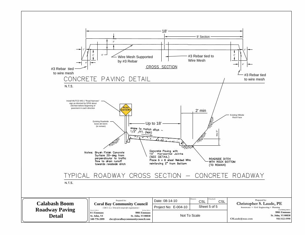
Up to 18'
18'
6"Wire Mesh Supportedby #3 Rebar
#3 Rebar tied toWire Mesh
3"
1"
4"
4"
1"
4"
4"
#3 Rebar tiedto wire mesh
#3 Rebar tiedto wire mesh
9' Section
Max
8"
2' min
Install MUTCD W5-1 "Road Narrows"sign as directed by DPW about
150-feet before beginning ofpavement in each direction
Existing Roadsideloose dirt berm
(to remain)
Existing HillsideRock Face
Prepared by:
Christopher S. Laude, PEStormwater ∞ Civil Engineering ∞ Planning
Local Mailing Address:
9901 Emmaus
St. John, VI 00830
[email protected] 910/612-5990
Prepared for:
Coral Bay Community Council- CBCC is a 501(c)(3) nonprofit organization -
Physical Address: Mailing Address:
8-1 Emmaus 9901 Emmaus
St. John, VI St. John, VI 00830
340-776-2099 [email protected]
Date: 08-14-10
Project No: E-004-10 Sheet 5 of 5CSL
Not To Scale
Calabash Boom
Roadway Paving
Detail
CSLDrawn: Checked:

Scope of Work & Details Calabash Boom Road
Grading, Drainage & Paving Improvements PROJECT NO. B001-09
APPENDIX A
SPECIFICATIONS
JAM Engineering Associates LLC Stormwater ∞ Civil Engineering ∞ Planning

Shipwreck Ghut Drainage Maintenance
Scope of Work, Details & Specifications (Revised to include Step Pools Only)
PROJECT NO. D2
SITUATE IN
CORAL BAY, ST. JOHN US VIRGIN ISLANDS
April 4, 2011
Revised May 5, 2011
PREPARED FOR:
Coral Bay Community Council, Inc., and: Virgin Islands Resource Conservation
& Development Council, Inc. NOAA-ARRA Grant
9901 Emmaus St. John, USVI 00830
PREPARED BY:
Christopher S. Laude, PE 9901 Emmaus
St John, VI 00830 (910) 612-5990
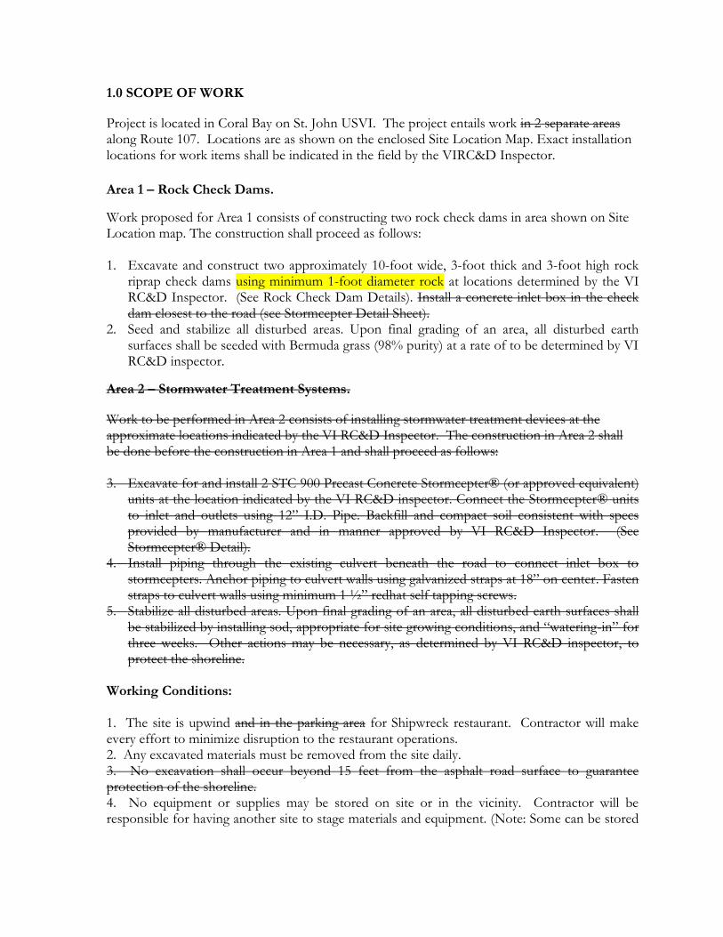
1.0 SCOPE OF WORK
Project is located in Coral Bay on St. John USVI. The project entails work in 2 separate areas along Route 107. Locations are as shown on the enclosed Site Location Map. Exact installation locations for work items shall be indicated in the field by the VIRC&D Inspector.
Area 1 – Rock Check Dams.
Work proposed for Area 1 consists of constructing two rock check dams in area shown on Site Location map. The construction shall proceed as follows: 1. Excavate and construct two approximately 10-foot wide, 3-foot thick and 3-foot high rock
riprap check dams using minimum 1-foot diameter rock at locations determined by the VI RC&D Inspector. (See Rock Check Dam Details). Install a concrete inlet box in the check dam closest to the road (see Stormcepter Detail Sheet).
2. Seed and stabilize all disturbed areas. Upon final grading of an area, all disturbed earth surfaces shall be seeded with Bermuda grass (98% purity) at a rate of to be determined by VI RC&D inspector.
Area 2 – Stormwater Treatment Systems.
Work to be performed in Area 2 consists of installing stormwater treatment devices at the approximate locations indicated by the VI RC&D Inspector. The construction in Area 2 shall be done before the construction in Area 1 and shall proceed as follows: 3. Excavate for and install 2 STC 900 Precast Concrete Stormcepter® (or approved equivalent)
units at the location indicated by the VI RC&D inspector. Connect the Stormcepter® units to inlet and outlets using 12” I.D. Pipe. Backfill and compact soil consistent with specs provided by manufacturer and in manner approved by VI RC&D Inspector. (See Stormcepter® Detail).
4. Install piping through the existing culvert beneath the road to connect inlet box to stormcepters. Anchor piping to culvert walls using galvanized straps at 18” on center. Fasten straps to culvert walls using minimum 1 ½” redhat self tapping screws.
5. Stabilize all disturbed areas. Upon final grading of an area, all disturbed earth surfaces shall be stabilized by installing sod, appropriate for site growing conditions, and “watering-in” for three weeks. Other actions may be necessary, as determined by VI RC&D inspector, to protect the shoreline.
Working Conditions: 1. The site is upwind and in the parking area for Shipwreck restaurant. Contractor will make every effort to minimize disruption to the restaurant operations. 2. Any excavated materials must be removed from the site daily. 3. No excavation shall occur beyond 15 feet from the asphalt road surface to guarantee protection of the shoreline. 4. No equipment or supplies may be stored on site or in the vicinity. Contractor will be responsible for having another site to stage materials and equipment. (Note: Some can be stored
on CBCC’s site in Coral Bay on King’s Hill rd. – check before bidding) 5. Work, particularly earth-moving, will be conducted in morning hours, as early as possible, with all work completed by 3 pm. 6. Project must take two weeks or less on site – and should be done between June 6th and June 17th on site. It cannot carry over into the following weeks due to STJ Festival/Carnival Activities. Contractor is required to provide staging schedule with bid, which will be evaluated in selection.
NOTES AND CONDITIONS
Additional specifications and adjustments, at the discretion of the VIRC&D Inspector, shall be field implemented to adequately install devices and provide protection and stabilization. Contractor shall be responsible for implementing any such adjustments as deemed necessary by the Inspector that are reasonably similar to the written specifications.
a. All materials and supplies including but not limited to grates, rock, concrete, Stormcepter ® and geotextile are to be provided by the contractor.
b. Contractor shall maintain traffic flow in at least one lane at all times using appropriate traffic control methods in accordance with all Public Works requirements.
c. During grading & excavation work, sufficient water will be kept onsite to ensure that exposed soil and road surfaces can be sprayed down to control dust.
d. All workmanship shall comply with VI DPW specifications and FP-2006 specifications. e. All grading and excavation included on this job shall include all rock and ledge removal
necessary to install items as specified. No additional fees shall be charged for rock work. f. Contractor shall be responsible for installing prior to start of construction up to four sign
posts consisting of a 4" x 4" post set 2' into the ground and extending 6' above grade at locations to be determined upon the start of construction. Signs will be provided by VIRCD and mounted on the signpost by the contractor.
g. BUY AMERICAN CLAUSE: Contractors are hereby notified that they are encouraged, to the greatest extent practicable, to purchase American-made equipment and products with funding provided under this award.
h. Contractor shall have a VI business license to do the type of work that is being performed.
i. Contractor shall provide a valid DUNS number. j. All workers on the projects must legally be able to work in the VI. k. Contractor shall notify Project manager, CBCC and all abutters at least 4 days prior to
beginning work. DPNR/CZM shall be notified 72 hours prior to beginning work. l. Contractor must conduct a weekly safety meeting for all on site personnel m. Provide $ 1 million liability insurance with CBCC and VIRC&D as named insured n. Comply with all Federal and VI, DPW and DPNR regulations and requirements.

ââ
.3,500 0 3,5001,750 Feet
Shipwreck Ghut Location Map
Shipwreck GhutProject Location

Pre
par
ed f
or:
Cora
l B
ay
Co
mm
un
ity
Co
un
cil
- C
BC
C i
s a 501(c
)(3)
nonpro
fit
org
aniz
ati
on -
Ph
ysi
cal
Ad
dre
ss:
Mai
lin
g A
dd
ress
:
8-1
Em
mau
s99
01
Em
mau
s
St.
John, V
IS
t. J
oh
n,
VI
00
83
03
40
-77
6-2
09
9cb
cc@
cora
lbay
com
munit
yco
unci
l.co
m
Dat
e: 0
3/31
/201
1
Pro
ject
No:
D2
She
et 3
of 4
CS
L
Not
To
Sca
le
Dra
ina
ge
Ma
inte
nan
ce
Sh
ipw
reck
Gh
ut
Co
ral
Ba
y, S
t J
oh
n,
US
VI
Pro
ject
La
yo
ut
Pre
par
ed b
y:
Ch
rist
op
her
S L
au
de
, P
.E.
Sto
rmw
ate
r Ð
C
ivil
Ð
P
lan
nin
g
Physi
cal
Addre
ss:
Mai
ling A
ddre
ss:
8-1
Em
mau
s9
90
1 E
mm
aus
St.
Jo
hn
, V
IS
t. J
oh
n, V
I 0
08
30
91
0-6
12
-59
90
csla
ud
e@m
ac.c
om

Pre
par
ed f
or:
Cora
l B
ay C
om
mu
nit
y C
ou
nci
l-
CB
CC
is
a
50
1(c
)(3
) n
on
pro
fit
org
an
iza
tio
n -
Ph
ysi
cal
Add
ress
:M
aili
ng
Ad
dre
ss:
8-1
Em
mau
s9901 E
mm
aus
St.
Jo
hn
, V
IS
t. J
ohn,
VI
00
83
0340-7
76-2
099
cbcc
@co
ralb
ayco
mm
un
ity
cou
nci
l.co
m
Dat
e: 0
3/31
/201
1
Pro
ject
No:
D2
She
et 3
of 4
CS
L
Not
To
Sca
le
Dra
inage
Main
ten
an
ce
Sh
ipw
reck
Gh
ut
Cora
l B
ay, S
t Joh
n,
US
VI
Ch
eck
Da
m D
eta
ils
Pre
par
ed b
y:
Ch
rist
op
her
S L
au
de
, P
.E.
Sto
rmw
ate
r Ð
C
ivil
Ð
P
lan
nin
gP
hysi
cal
Addre
ss:
Mai
ling A
ddre
ss:
8-1
Em
mau
s9901 E
mm
aus
St.
John,
VI
St.
John,
VI
00830
910-6
12-5
990
csla
ude@
mac
.com
Calabash Boom Road Supplemental
Drainage Improvements Scope of Work, Details & Specifications
PROJECT NO. D1 - Phase II
SITUATE IN
CORAL BAY, ST. JOHN US VIRGIN ISLANDS
June 8, 2011
PREPARED FOR:
Coral Bay Community Council, Inc., and: Virgin Islands Resource Conservation
& Development Council, Inc. NOAA-ARRA Grant
9901 Emmaus St. John, USVI 00830
PREPARED BY:
Christopher S. Laude, PE 9901 Emmaus
St John, VI 00830 910/612-5990
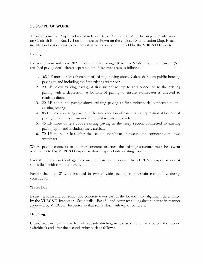
1.0 SCOPE OF WORK
This supplemental Project is located in Coral Bay on St. John USVI. The project entails work on Calabash Boom Road . Locations are as shown on the enclosed Site Location Map. Exact installation locations for work items shall be indicated in the field by the VIRC&D Inspector.
Paving Excavate, form and pave 302 LF of concrete paving 18’ wide x 6” deep, wire reinforced, (See attached paving detail sheet) separated into 6 separate areas as follows:
1. 62 LF more or less from top of existing paving above Calabash Boom public housing paving to and including the first existing water bar.
2. 20 LF below existing paving at first switchback up to and connected to the existing paving with a depression at bottom of paving to ensure stormwater is directed to roadside ditch.
3. 20 LF additional paving above existing paving at first switchback, connected to the existing paving.
4. 85 LF below existing paving in the steep section of road with a depression at bottom of paving to ensure stormwater is directed to roadside ditch.
5. 45 LF more or less above existing paving in the steep section connected to existing paving up to and including the waterbar.
6. 70 LF more or less after the second switchback between and connecting the two waterbars.
Where paving connects to another concrete structure the existing structure must be sawcut where directed by VI RC&D inspector, doweling steel into existing concrete. Backfill and compact soil against concrete in manner approved by VI RC&D inspector so that soil is flush with top of concrete. Paving shall be 18’ wide installed in two 9’ wide sections to maintain traffic flow during construction. Water Bar Excavate, form and construct two concrete water bars at the location and alignment determined by the VI RC&D Inspector. See details. Backfill and compact soil against concrete in manner approved by VI RC&D Inspector so that soil is flush with top of concrete. Ditching. Clean/excavate 579 linear feet of roadside ditching in two separate areas - before the second switchback and after the second switchback as follows:

1. 261 LF of cleaning/excavating the ditch below the second switchback in a location determined
by the VI RC&D Inspector. (See Roadside Ditch Detail). 2. 318 LF of cleaning/excavating the ditch above the second switchback in a location determined
by the VI RC&D Inspector. (See Roadside Ditch Detail).
Rock Check Dam. Excavate, form and construct rock check dams at the location and alignment determined by the VI RC&D Inspector. See details.
NOTES AND CONDITIONS
Additional specifications and adjustments, at the discretion of the VIRC&D Inspector, shall be field implemented to adequately install devices and provide protection and stabilization. Contractor shall be responsible for implementing any such adjustments as deemed necessary by the Inspector that are reasonably similar to the written specifications.
a. All materials and supplies including but not limited to rock, concrete, and geotextile are to be provided by the contractor.
b. Contractor shall barricade freshly poured concrete for a minimum of 48 hours from the end of pour to prevent damage from traffic. All concrete shall have a minimum compressive strength at 28-days of 3,000 pounds per square inch (psi). Two test cylinders per pour shall be required. Contractor shall notify VI RC&D Inspector at least 24-hours in advance of each and every concrete pour so that the Inspector may verify construction. Contractor shall not pour any concrete unless the work has been observed and approved by the Inspector.
c. Contractor shall remove excess excavated material from the site. At the direction of the VI RC&D inspector, contractor may use such material to fill eroded roadway and roadside areas. All non-traffic areas filled and repaired, and all other disturbed areas shall be protected with Erosion Control Blanket (at the direction of the VI RC&D inspector) and seeded with Bermuda grass (98% purity) at 20lbs. per acre. No material other than that used for roadside repairs shall remain onsite. VIRCD shall provide Erosion Control Blanket, contractor shall install erosion control blanket and seed with Bermuda grass at specified rate.
d. Contractor shall maintain traffic flow in at least one lane at all times using appropriate traffic control methods in accordance with all Public Works requirements.
e. During grading & excavation work, sufficient water will be kept onsite to ensure that exposed soil and road surfaces can be sprayed down to control dust.
f. All workmanship shall comply with VI DPW specifications and FP-2006 specifications. g. All grading and excavation included on this job shall include all rock and ledge removal
necessary to install items as specified. No additional fees shall be charged for rock work. h. BUY AMERICAN CLAUSE: Contractors are hereby notified that they are encouraged,
to the greatest extent practicable, to purchase American-made equipment and products with funding provided under this award.

i. Contractor shall have a VI business license to do the type of work that is being performed.
j. Contractor shall provide a valid DUNS number. k. All workers on the projects must legally be able to work in the VI. l. Contractor shall notify Project manager, CBCC and all abutters at least 4 days prior to
beginning work. DPNR/CZM shall be notified 72 hours prior to beginning work. m. Contractor must conduct a weekly safety meeting for all on site personnel n. Provide $ 1 million liability insurance with CBCC and VIRC&D as named insured o. Comply with all Federal and VI, DPW and DPNR regulations and requirements.
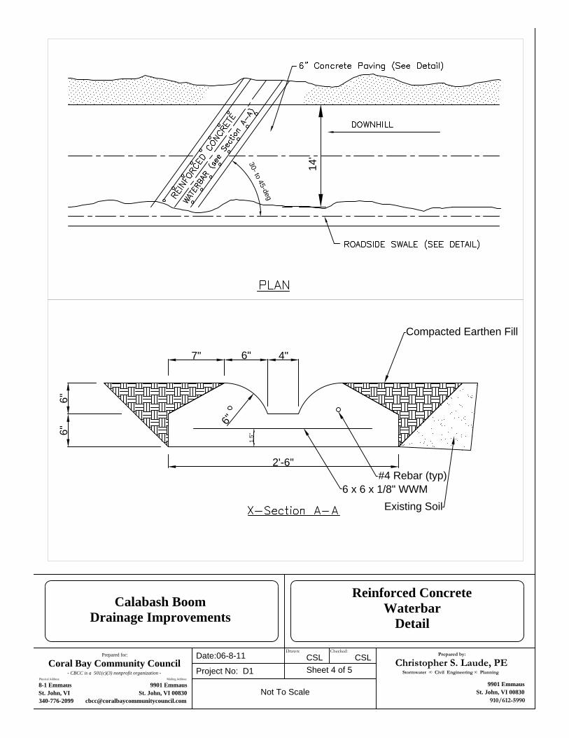
14'30- to 45-deg
2'-6"
6"6"
6"
7" 6" 4"
Compacted Earthen Fill
Existing Soil
1.5"
6 x 6 x 1/8" WWM#4 Rebar (typ)
Prepared for:
Coral Bay Community Council- CBCC is a 501(c)(3) nonprofit organization -
Physical Address: Mailing Address:
8-1 Emmaus 9901 Emmaus
St. John, VI St. John, VI 00830
340-776-2099 [email protected]
Date:06-8-11
Project No: D1 Sheet 4 of 5CSL
Not To Scale
Calabash Boom
Drainage Improvements
Reinforced Concrete
Waterbar
Detail
CSLDrawn: Checked:
Prepared by:
Christopher S. Laude, PEStormwater ∞ Civil Engineering ∞ Planning
9901 Emmaus
St. John, VI 00830
910/612-5990

18-ft
Wire Mesh Supportedby concrete blocks
4"
6" Min
6" min
Existing HillsideRock Face
Extend ConcreteDown toCompetent Rock
Concrete paving with 15' horizontal joints
Excavate so top of pavement is flush withexisting grade. Backfill and Compact Soilto Top of Pavement
6"
2' min
6 x 6 Wire Mesh Supportedby concrete blocks
4"
Fiberboard ExpansionJoint every 25 LF Existing Concrete
Existing Grade
Backfill to ConcreteSurface and Compact
Match Concrete Surfaceto Existing Grade
Set Concrete Sub-grade on Rockor Compacted natural soils.
3" or to Rock
6"
Attach with 12" #4bars grouted 6" intoexisting concrete at12" O.C.
Max. 8" depth or3H:1V slope
Prepared by:
Christopher S. Laude, PEStormwater ∞ Civil Engineering ∞ Planning
Local Mailing Address:
9901 Emmaus
St. John, VI 00830
[email protected] 910/612-5990
Prepared for:
Coral Bay Community Council- CBCC is a 501(c)(3) nonprofit organization -
Physical Address: Mailing Address:
8-1 Emmaus 9901 Emmaus
St. John, VI St. John, VI 00830
340-776-2099 [email protected]
Date: 06-09-11
Project No: D1 Sheet 5 of 5CSL
Not To Scale
Calabash Boom
Roadway Paving
Detail
CSLDrawn: Checked:

Existing HillsideRock Face
Rock Check DamMin 1' dia. Rip Rap
Existing Concrete Pavement
Prepared by:
Christopher S. Laude, PEStormwater ∞ Civil Engineering ∞ Planning
9901 Emmaus
St. John, VI 00830
910/612-5990
Prepared for:
Coral Bay Community Council- CBCC is a 501(c)(3) nonprofit organization -
Physical Address: Mailing Address:
8-1 Emmaus 9901 Emmaus
St. John, VI St. John, VI 00830
340-776-2099 [email protected]
Date: 06-09-11
Project No: D1 Sheet 3 of 5CSL
Not To Scale
Calabash Boom
Drainage Improvements
Rock Check Dam Details
CSLDrawn: Checked:
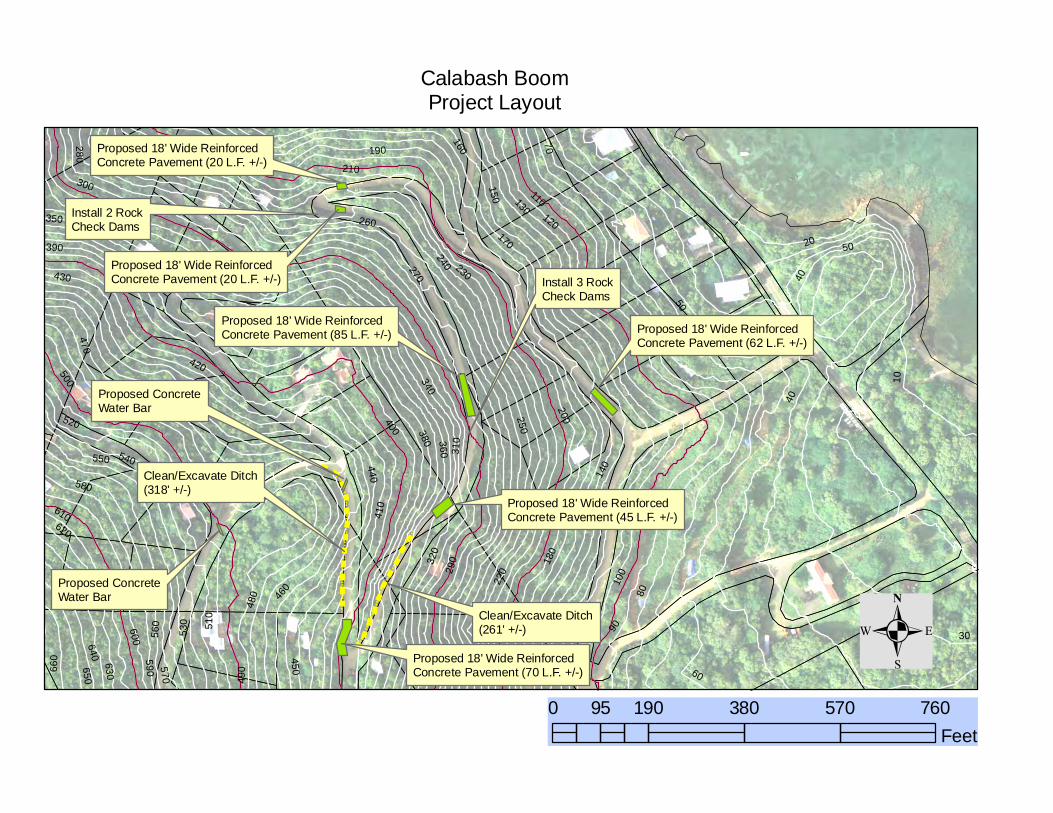
!!
!!
!!
!!
!!
!!
!!
!!
!!
!!
! !!!
!
!
!!
!!
!!
!!
!!
!!
!!
!!
!!
!
Clean/Excavate Ditch(261' +/-)
Clean/Excavate Ditch(318' +/-)
Proposed 18' Wide ReinforcedConcrete Pavement (70 L.F. +/-)
Proposed 18' Wide ReinforcedConcrete Pavement (45 L.F. +/-)
Proposed 18' Wide ReinforcedConcrete Pavement (85 L.F. +/-) Proposed 18' Wide Reinforced
Concrete Pavement (62 L.F. +/-)
Proposed 18' Wide ReinforcedConcrete Pavement (20 L.F. +/-)
Proposed 18' Wide ReinforcedConcrete Pavement (20 L.F. +/-)
Proposed ConcreteWater Bar
Install 2 RockCheck Dams
Install 3 RockCheck Dams
Proposed ConcreteWater Bar
40
30
50
60
70
80
20
90
300
290
31
0
28
0
270
220
260
230
240
250
210
10
200
190
180
160
170
320
110
340
350
150
36
014
010
0
120
130
380
390
400
410
420
430
440
45
0
460
470
480
49
0
500
51
0
520
53
0
540550
56
0
570
580
59
0
600
610620
630
640650
66
0
40
50
Calabash BoomProject Layout
.0 190 380 570 76095
Feet