Embed Size (px)
Citation preview
1
Noise Canceling Headphones Shizhang Wu
Supervisor: Ed Richter, Arye Nehorai, Walter Chen
Department of Electrical and Systems Engineering
Washington University in St. Louis Fall 2008
Abstract—In this undergraduate research project, we built a noise canceling headphone with a negative feedback system. We set up the microphone inside the ear cup of the headphone. The tradeoff in this design is the performance and the stability of the system. Our headphone can attenuate the noise for the frequency below 1 KHz and achieve at least 10 dB noise attenuation below 400 Hz. We calculated the theoretical frequency response and verified it with Matlab. The circuit was designed in Pspice and tested by generating the noise from another headphone. The system achieved the best performance under the stable condition.
1. Introduction Noise Canceling Headphones (NCHs) reduce the noise from active noise cancelation. By their nature, headphone's ear cups are able to block out some high frequency noise because it is absorbed. However, the passive noise attenuation through ear cups is not efficient for low frequency noise. Thus, it is necessary to have the active noise cancelation to reduce the low frequency noise, such as noise below 1 KHz. [1] For this undergraduate research project, we build a Noise Canceling Headphones inspired by Bose's patent [2]. The system is a close loop system and can attenuate the noise below 1 KHz. In this report, I will present the background, the theoretical calculation verified by Matlab, the Pspice circuit analysis and the real circuit performance.
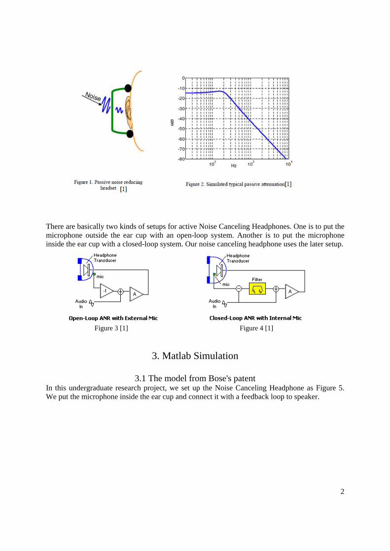
2. Background As mentioned above, passive attenuation is achieved when ear cups is sealed to the user's ears to block the external noise. This is illustrated in Figure 1 [1]. The frequency response of passive attenuation for a typical headset is illustrated in Figure 2 [1], showing about 15 dB of attenuation below the mechanical cut-off frequency 220 Hz, and an increasing attenuation above the cut-off frequency. From Figure 2 it is clear that additional active attenuation at the low frequencies can improve the overall attenuation performance.
2
There are basically two kinds of setups for active Noise Canceling Headphones. One is to put the microphone outside the ear cup with an open-loop system. Another is to put the microphone inside the ear cup with a closed-loop system. Our noise canceling headphone uses the later setup.
Figure 3 [1] Figure 4 [1]
3. Matlab Simulation
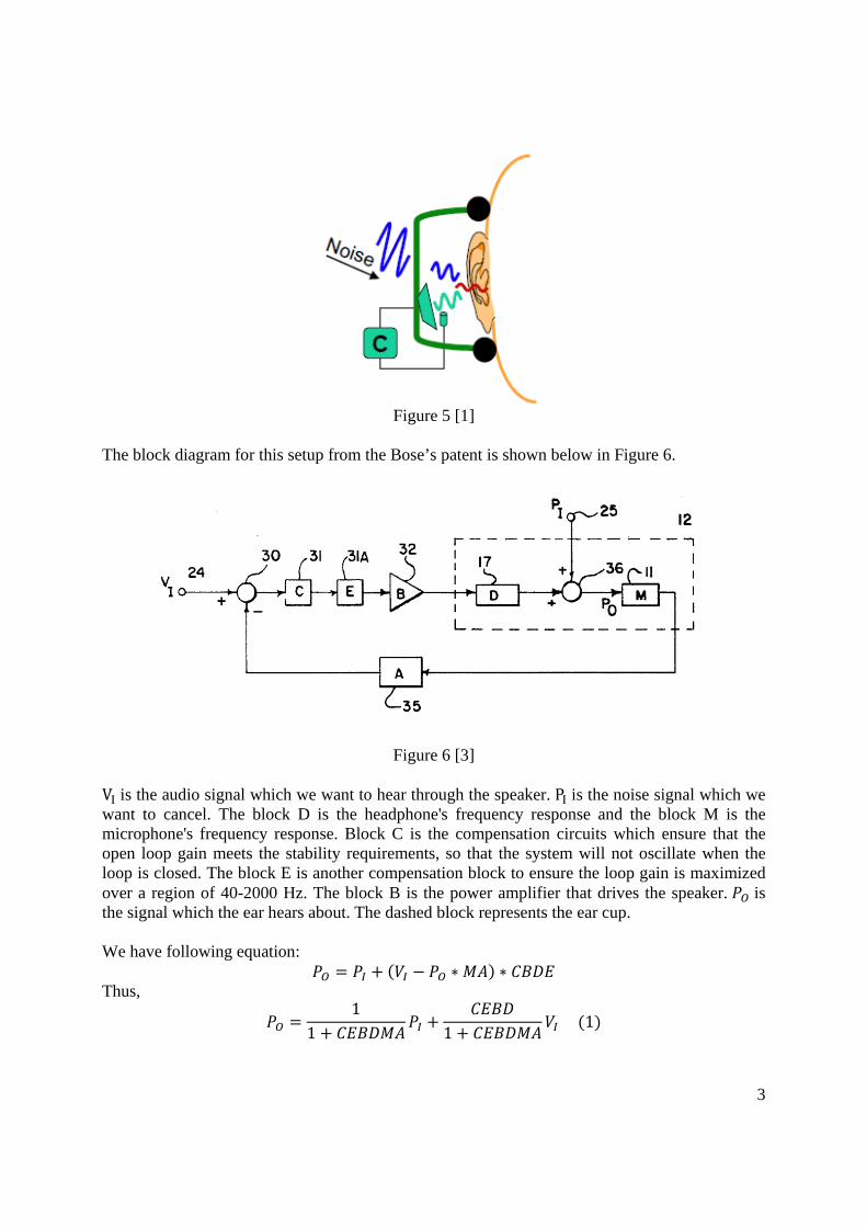
3.1 The model from Bose's patent In this undergraduate research project, we set up the Noise Canceling Headphone as Figure 5. We put the microphone inside the ear cup and connect it with a feedback loop to speaker.
3
Figure 5 [1]
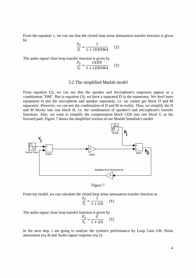
The block diagram for this setup from the Bose’s patent is shown below in Figure 6.
Figure 6 [3]
VI is the audio signal which we want to hear through the speaker. PI is the noise signal which we want to cancel. The block D is the headphone's frequency response and the block M is the microphone's frequency response. Block C is the compensation circuits which ensure that the open loop gain meets the stability requirements, so that the system will not oscillate when the loop is closed. The block E is another compensation block to ensure the loop gain is maximized over a region of 40-2000 Hz. The block B is the power amplifier that drives the speaker. is the signal which the ear hears about. The dashed block represents the ear cup. We have following equation:
Thus,
11 1
1
4
From the equation 1, we can see that the closed loop noise attenuation transfer function is given by
11
2
The audio signal close loop transfer function is given by
1 3
3.2 The simplified Matlab model
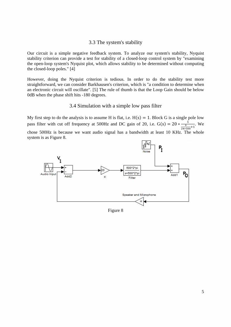
From equation (2), we can see that the speaker and microphone's responses appear as a combination "DM". But in equation (3), we have a separated D in the numerator. We don't have equipment to test the microphone and speaker separately, i.e. we cannot get block D and M separately. However, we can test the combination of D and M in reality. Thus, we simplify the D and M blocks into one block H, i.e. the combination of speaker's and microphone's transfer functions. Also, we want to simplify the compensation block CEB into one block G as the forward path. Figure 7 shows the simplified version of our Matlab Simulink's model.
Figure 7
From my model, we can calculate the closed loop noise attenuation transfer function as
11
4
The audio signal close loop transfer function is given by
1 5
In the next step, I am going to analyze the system's performance by Loop Gain GH, Noise attenuation (eq 4) and Audio signal response (eq 5).
5
3.3 The system's stability Our circuit is a simple negative feedback system. To analyze our system's stability, Nyquist stability criterion can provide a test for stability of a closed-loop control system by "examining the open-loop system's Nyquist plot, which allows stability to be determined without computing the closed-loop poles." [4] However, doing the Nyquist criterion is tedious. In order to do the stability test more straightforward, we can consider Barkhausen's criterion, which is "a condition to determine when an electronic circuit will oscillate". [5] The rule of thumb is that the Loop Gain should be below 0dB when the phase shift hits -180 degrees.
3.4 Simulation with a simple low pass filter
My first step to do the analysis is to assume H is flat, i.e. H s 1. Block G is a single pole low
pass filter with cut off frequency at 500Hz and DC gain of 20, i.e. G s 20 . We
chose 500Hz is because we want audio signal has a bandwidth at least 10 KHz. The whole system is as Figure 8.
Figure 8
6
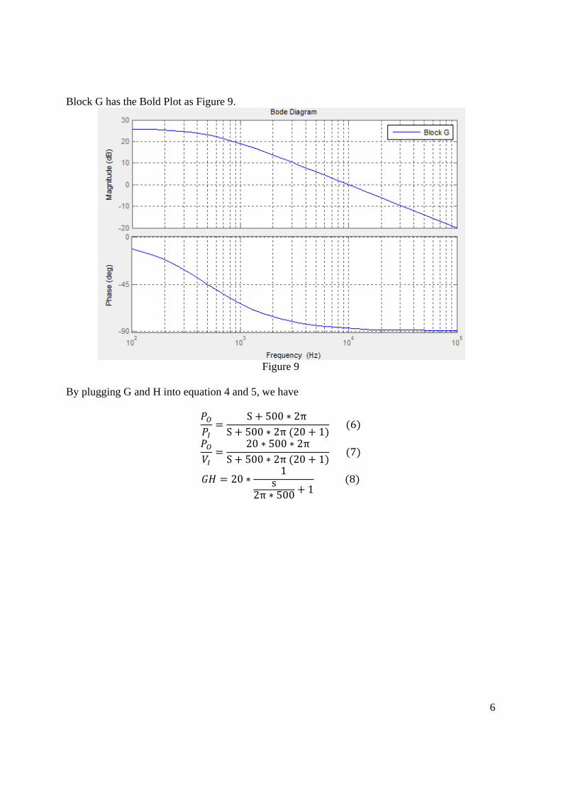
Block G has the Bold Plot as Figure 9.
Figure 9
By plugging G and H into equation 4 and 5, we have
S 500 2π S 500 2π 20 1
6
20 500 2πS 500 2π 20 1
7
201
s2π 500 1
8
7
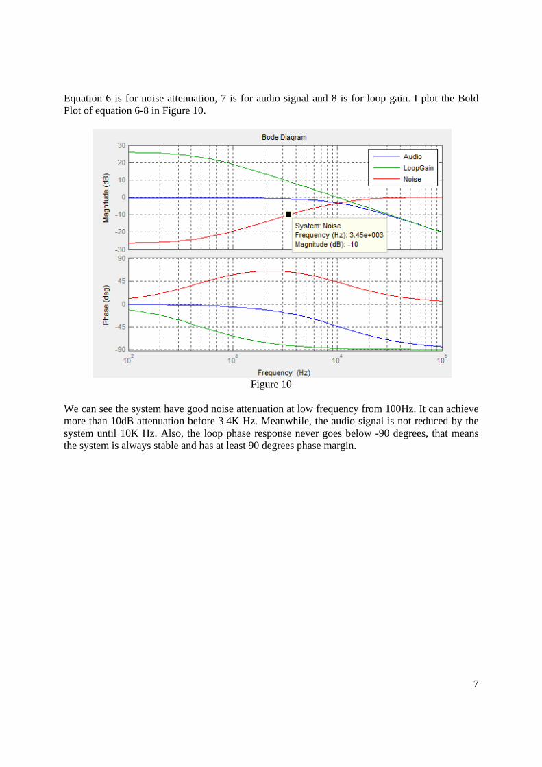
Equation 6 is for noise attenuation, 7 is for audio signal and 8 is for loop gain. I plot the Bold Plot of equation 6-8 in Figure 10.
Figure 10
We can see the system have good noise attenuation at low frequency from 100Hz. It can achieve more than 10dB attenuation before 3.4K Hz. Meanwhile, the audio signal is not reduced by the system until 10K Hz. Also, the loop phase response never goes below -90 degrees, that means the system is always stable and has at least 90 degrees phase margin.
8
3.5 Modeling the speaker's and microphone's frequency response
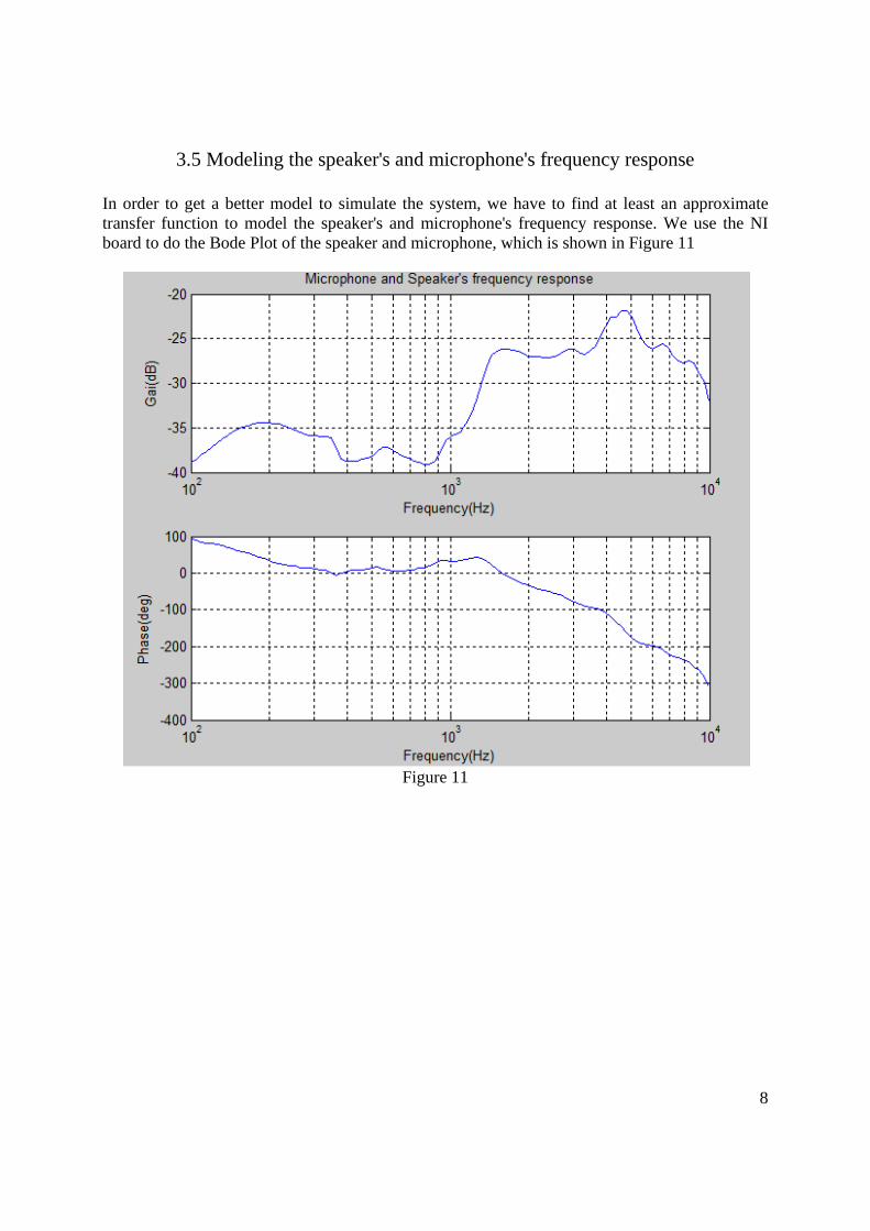
In order to get a better model to simulate the system, we have to find at least an approximate transfer function to model the speaker's and microphone's frequency response. We use the NI board to do the Bode Plot of the speaker and microphone, which is shown in Figure 11
Figure 11
9
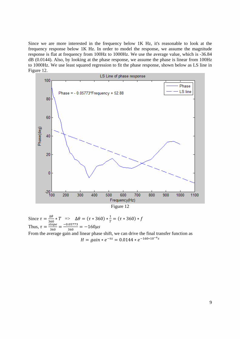
Since we are more interested in the frequency below 1K Hz, it's reasonable to look at the frequency response below 1K Hz. In order to model the response, we assume the magnitude response is flat at frequency from 100Hz to 1000Hz. We use the average value, which is -36.84 dB (0.0144). Also, by looking at the phase response, we assume the phase is linear from 100Hz to 1000Hz. We use least squared regression to fit the phase response, shown below as LS line in Figure 12.
Figure 12
Since ∆
=> ∆ 360 360
Thus, .
160
From the average gain and linear phase shift, we can drive the final transfer function as 0.0144
10
3.6 Simulation of the final design
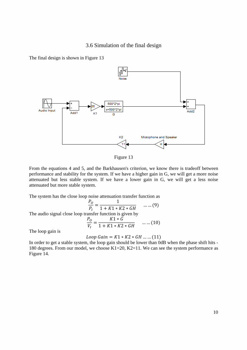
The final design is shown in Figure 13
Figure 13
From the equations 4 and 5, and the Barkhausen's criterion, we know there is tradeoff between performance and stability for the system. If we have a higher gain in G, we will get a more noise attenuated but less stable system. If we have a lower gain in G, we will get a less noise attenuated but more stable system. The system has the close loop noise attenuation transfer function as
11 1 2
…… 9
The audio signal close loop transfer function is given by 1
1 1 2 …… 10
The loop gain is 1 2 …… 11
In order to get a stable system, the loop gain should be lower than 0dB when the phase shift hits -180 degrees. From our model, we choose K1=20, K2=11. We can see the system performance as Figure 14.
11
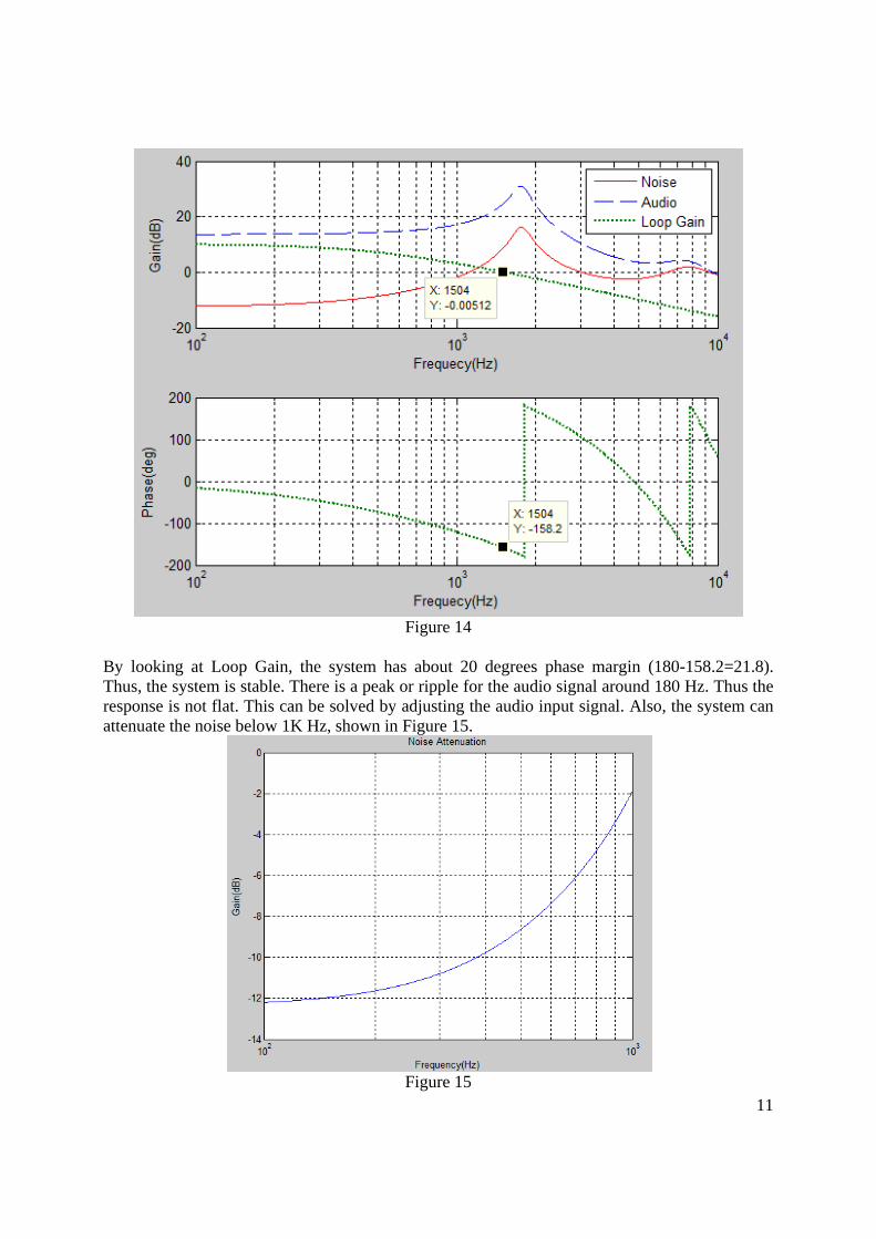
Figure 14
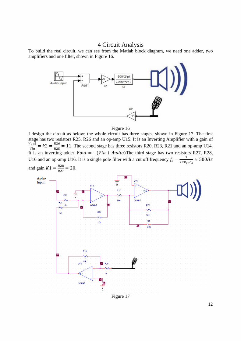
By looking at Loop Gain, the system has about 20 degrees phase margin (180-158.2=21.8). Thus, the system is stable. There is a peak or ripple for the audio signal around 180 Hz. Thus the response is not flat. This can be solved by adjusting the audio input signal. Also, the system can attenuate the noise below 1K Hz, shown in Figure 15.
Figure 15
12
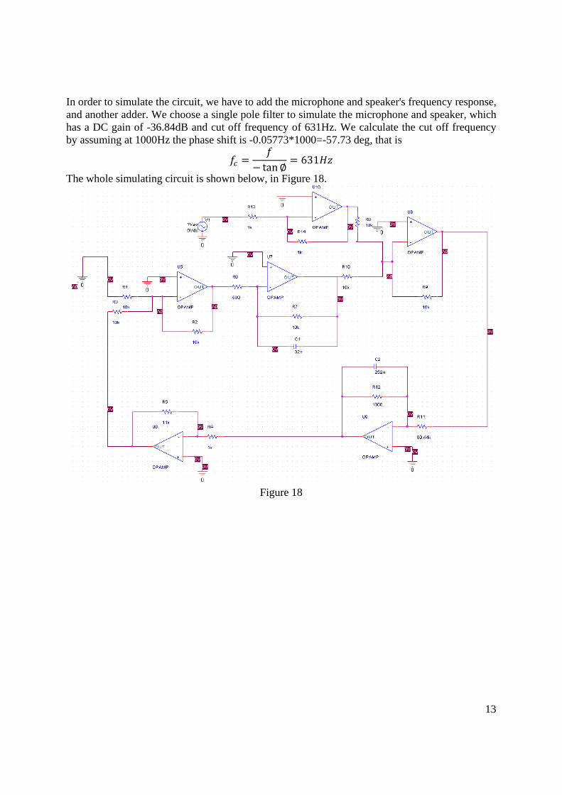
4 Circuit Analysis To build the real circuit, we can see from the Matlab block diagram, we need one adder, two amplifiers and one filter, shown in Figure 16.
Figure 16
I design the circuit as below; the whole circuit has three stages, shown in Figure 17. The first stage has two resistors R25, R26 and an op-amp U15. It is an Inverting Amplifier with a gain of
2 11. The second stage has three resistors R20, R23, R21 and an op-amp U14.
It is an inverting adder. The third stage has two resistors R27, R28,
U16 and an op-amp U16. It is a single pole filter with a cut off frequency 500
and gain 1 20.
Figure 17
13
In order to simulate the circuit, we have to add the microphone and speaker's frequency response, and another adder. We choose a single pole filter to simulate the microphone and speaker, which has a DC gain of -36.84dB and cut off frequency of 631Hz. We calculate the cut off frequency by assuming at 1000Hz the phase shift is -0.05773*1000=-57.73 deg, that is
tan631
The whole simulating circuit is shown below, in Figure 18.
Figure 18
14
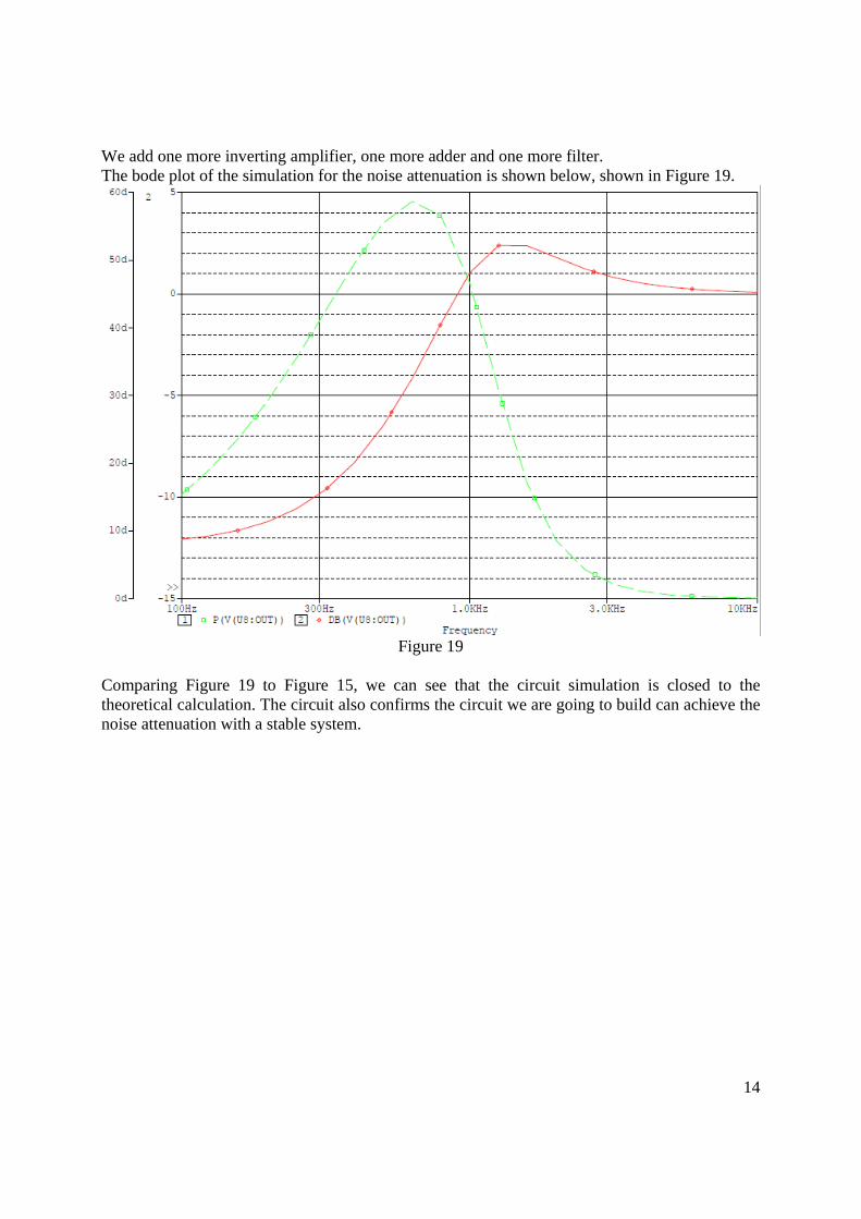
We add one more inverting amplifier, one more adder and one more filter. The bode plot of the simulation for the noise attenuation is shown below, shown in Figure 19.
Figure 19
Comparing Figure 19 to Figure 15, we can see that the circuit simulation is closed to the theoretical calculation. The circuit also confirms the circuit we are going to build can achieve the noise attenuation with a stable system.
15
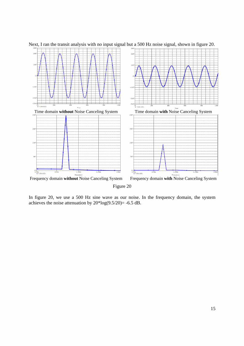
Next, I ran the transit analysis with no input signal but a 500 Hz noise signal, shown in figure 20.
Time domain without Noise Canceling System Time domain with Noise Canceling System
Frequency domain without Noise Canceling System Frequency domain with Noise Canceling System
Figure 20 In figure 20, we use a 500 Hz sine wave as our noise. In the frequency domain, the system achieves the noise attenuation by 20*log(9.5/20)= -6.5 dB.
16
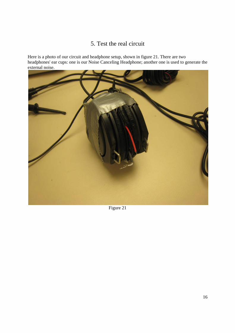
5. Test the real circuit
Here is a photo of our circuit and headphone setup, shown in figure 21. There are two headphones' ear cups: one is our Noise Canceling Headphone; another one is used to generate the external noise.
Figure 21
17
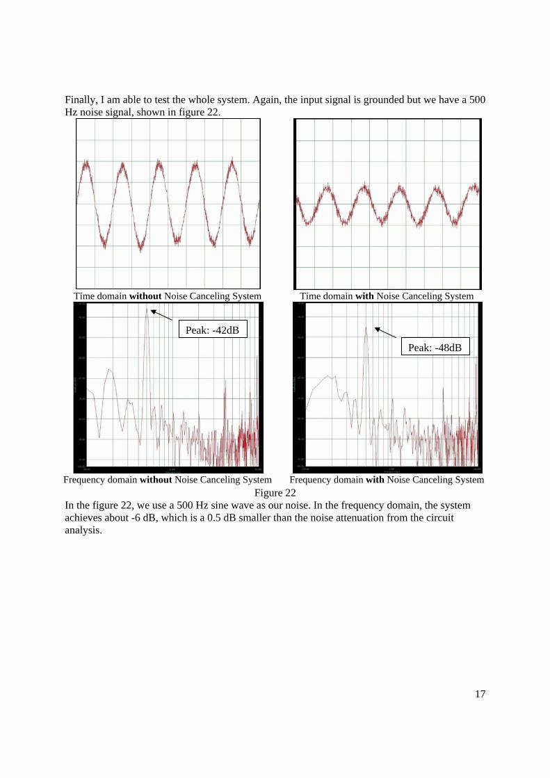
Finally, I am able to test the whole system. Again, the input signal is grounded but we have a 500 Hz noise signal, shown in figure 22.
Time domain without Noise Canceling System Time domain with Noise Canceling System
Frequency domain without Noise Canceling System Frequency domain with Noise Canceling System Figure 22
In the figure 22, we use a 500 Hz sine wave as our noise. In the frequency domain, the system achieves about -6 dB, which is a 0.5 dB smaller than the noise attenuation from the circuit analysis.
Peak: -42dB
Peak: -48dB
18
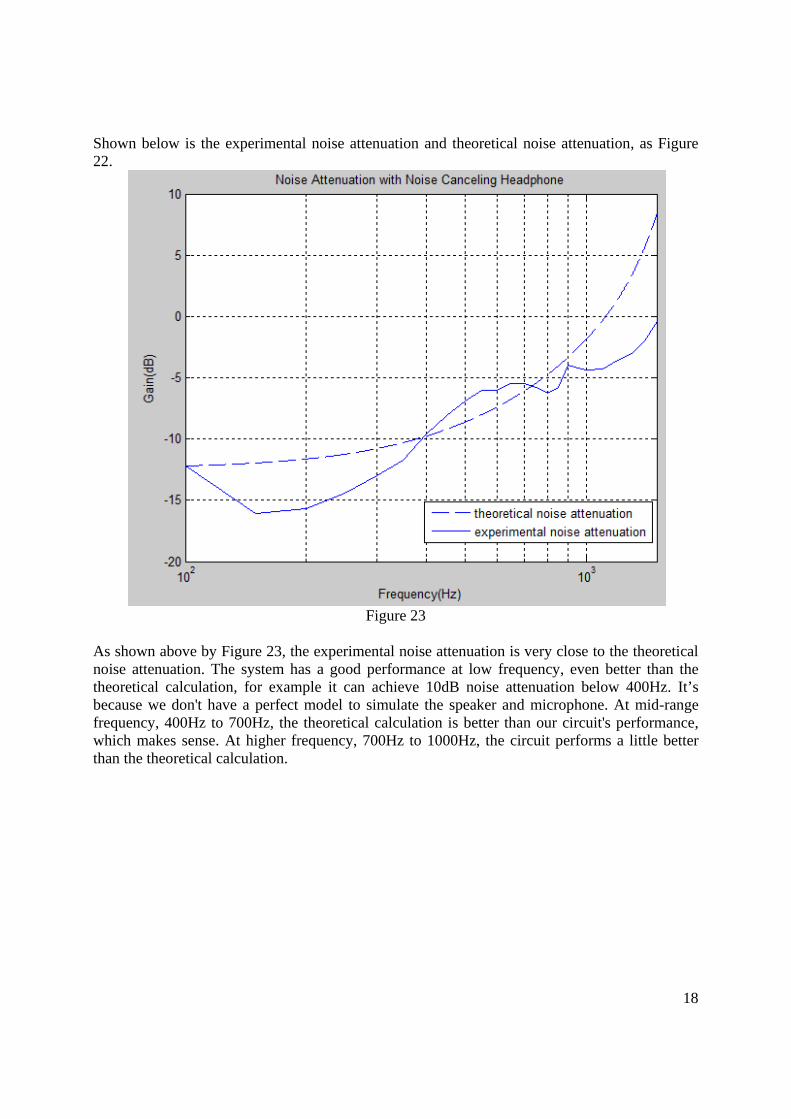
Shown below is the experimental noise attenuation and theoretical noise attenuation, as Figure 22.
Figure 23
As shown above by Figure 23, the experimental noise attenuation is very close to the theoretical noise attenuation. The system has a good performance at low frequency, even better than the theoretical calculation, for example it can achieve 10dB noise attenuation below 400Hz. It’s because we don't have a perfect model to simulate the speaker and microphone. At mid-range frequency, 400Hz to 700Hz, the theoretical calculation is better than our circuit's performance, which makes sense. At higher frequency, 700Hz to 1000Hz, the circuit performs a little better than the theoretical calculation.
19
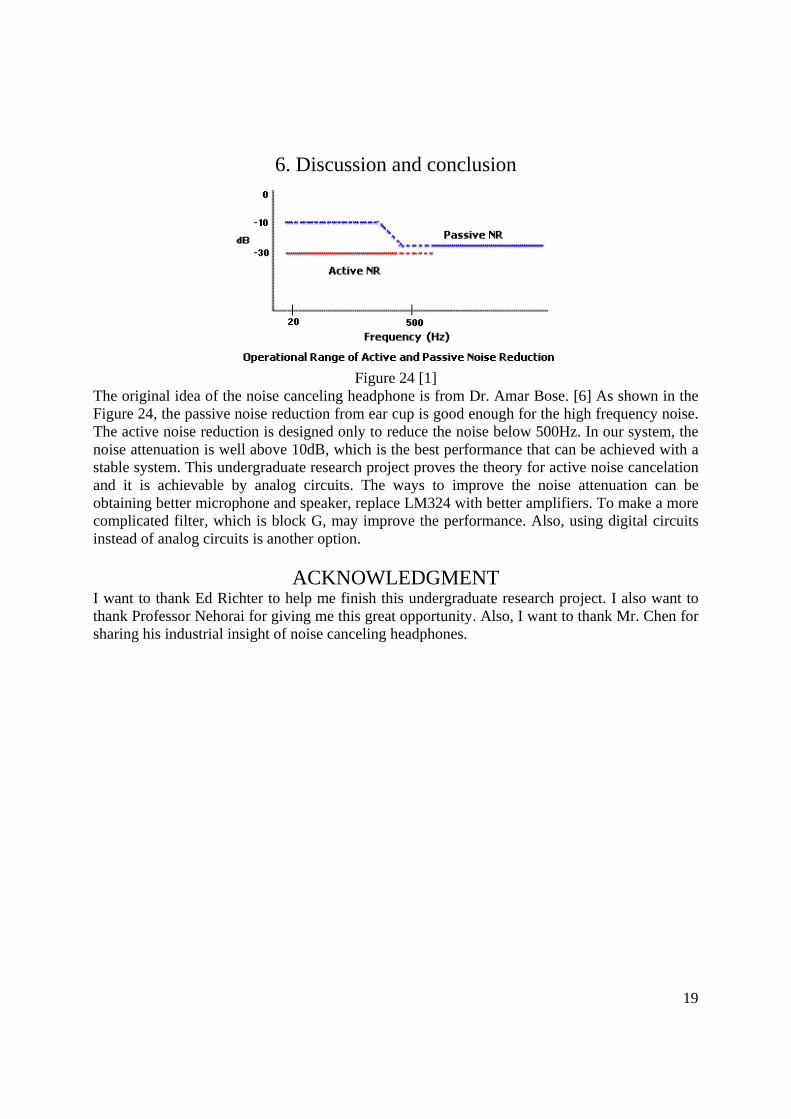
6. Discussion and conclusion
Figure 24 [1]
The original idea of the noise canceling headphone is from Dr. Amar Bose. [6] As shown in the Figure 24, the passive noise reduction from ear cup is good enough for the high frequency noise. The active noise reduction is designed only to reduce the noise below 500Hz. In our system, the noise attenuation is well above 10dB, which is the best performance that can be achieved with a stable system. This undergraduate research project proves the theory for active noise cancelation and it is achievable by analog circuits. The ways to improve the noise attenuation can be obtaining better microphone and speaker, replace LM324 with better amplifiers. To make a more complicated filter, which is block G, may improve the performance. Also, using digital circuits instead of analog circuits is another option.
ACKNOWLEDGMENT I want to thank Ed Richter to help me finish this undergraduate research project. I also want to thank Professor Nehorai for giving me this great opportunity. Also, I want to thank Mr. Chen for sharing his industrial insight of noise canceling headphones.
20
Reference [1] Chu Moy, Active Noise Reduction Headphone Systems, 2001, http://headwize.com/tech/anr_tech.htm [2] Bose, Amar, "Headphoning," US Patent No. 4,455,675, 6/19/84. [3] Shaw, E. A. G. and Thiessen, G. J. “Acoustics of circumaural earphones,” Journal of the Acoustical Society of America, 1962, 34(9), 1233-1246. [4] Wikipedia, Nyquist stability criterion, 15 April 2009 http://en.wikipedia.org/wiki/Nyquist_stability_criterion [5] Wikipedia, Barkhausen_stability_criterion, 15 April 2009 http://en.wikipedia.org/wiki/Barkhausen_stability_criterion [6] Bose, The World is a Noisy Place, 2009 April 26, 2009, http://www.bose.com/controller?event=VIEW_STATIC_PAGE_EVENT&url=/learning/escape_the_noise.jsp [7] Bartels, Volker, "Headset with Active Noise Reduction System for Mobile Applications," J. Audio Eng. Soc. April 1992, p. 277. [8] Bartels, Volker, "Sound Reproduction Device with Active Noise Compensation," US Patent No. 5,809,156, 9/15/98. [9] Eriksson, Larry J., "Active Sound Attenuation System with On-Line Adaptive Feedback Cancellation," US Patent No. 4,677,677, 6/30/87. [10] Feintuch, Paul, "Active Adaptive Noise Canceller without Training Mode," US Patent No. 5,117,401, 5/26/92. [11] Kyle, Gordon, "Ear Protection and Hearing Device," US Patent No. 3,952,158, 4/20/76. [12] Lo, Allen K., "Multiple Adaptive Filter Active Noise Canceller," US Patent No. 5,425,105, 6/13/95. [13] Sapiejewski, Roman, "High Compliance Headphone Driving," US Patent No. 5,181,252, 1/19/93. [14] Williams, Richard David, "Hearing Protector," US Patent No. 4064362, 12/20/77.