Embed Size (px)
Citation preview
Noise Driven In PackageDecoupling CapacitorOptimization for Power Integrity
Jun Chen and Lei He
Design Automation Laboratory, UCLA

Outline
IntroductionElectrical models Incremental impedance computation and
noise computationOptimization resultsConclusion
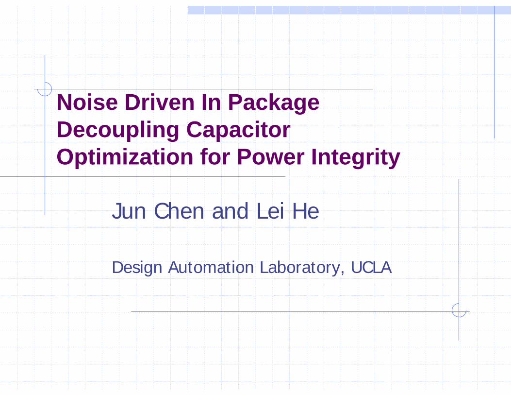
Power IntegrityNoise in power delivery system (PDS)
IR dropdI/dt dropResonance
Challenges in advanced high-performance package
Hugh power consumptionLarge current
High clock frequencyLarge inductive effects and
resonance
Large number of I/O’s SSN
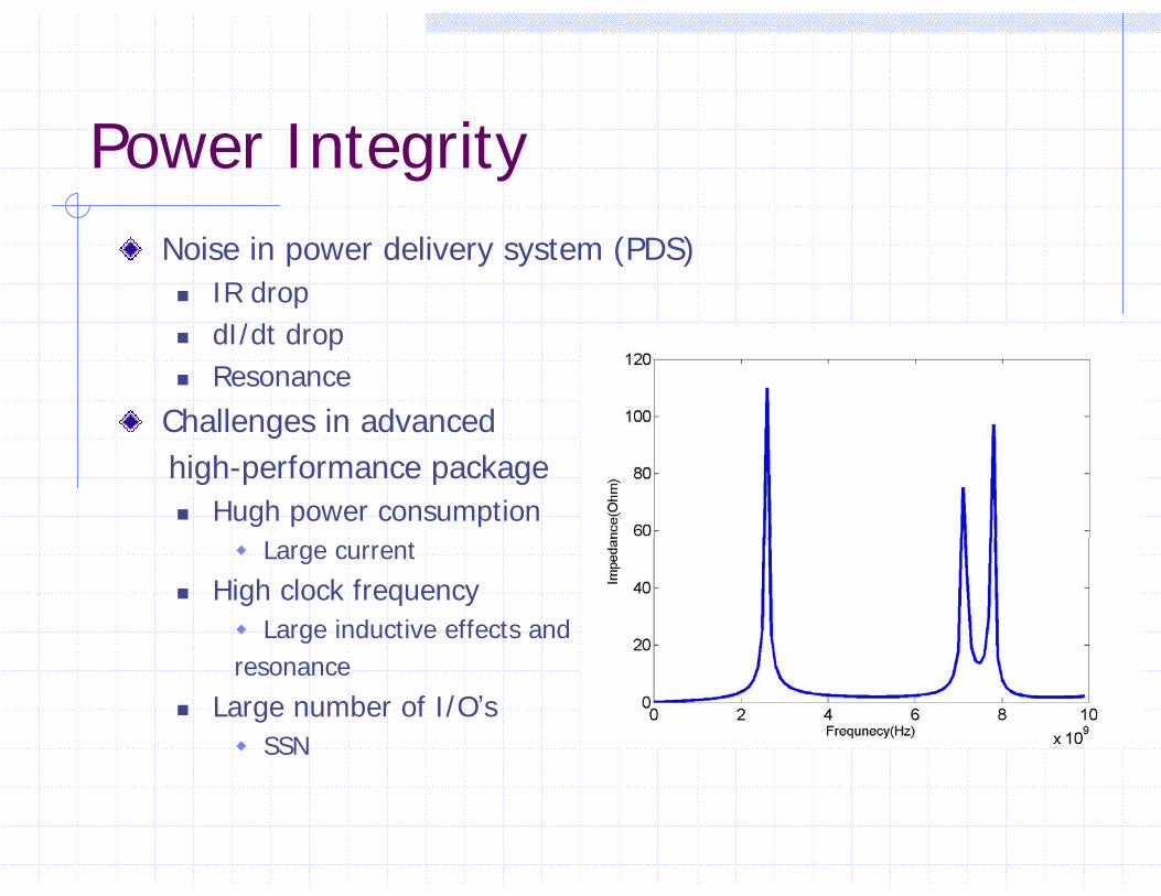
Decoupling capacitorsImprove power integrity with decoupling capacitors
Low impedance pathTemporary current source
In-Package decoupling capacitors for package
Discrete elementsDiscrete ESC, ESL, ESR Different effective frequenciesDifferent in costs
Decap 1 Decap 2
In-Package decoupling capacitor optimization problem
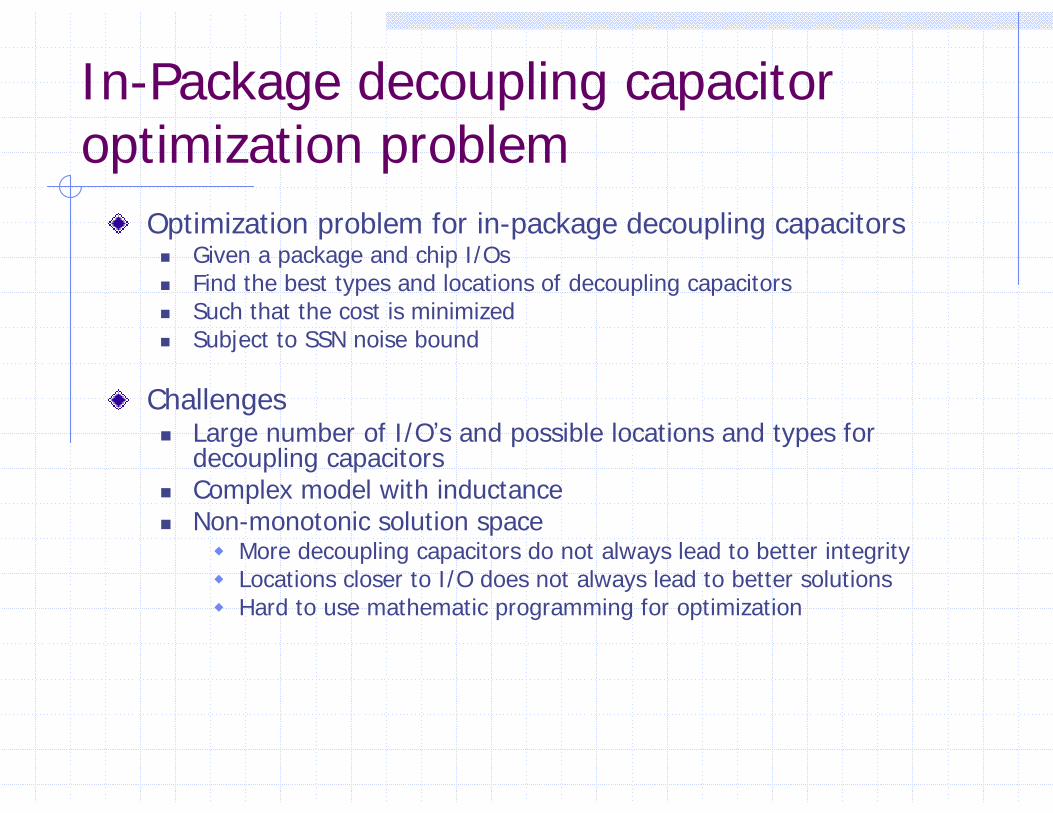
Optimization problem for in-package decoupling capacitorsGiven a package and chip I/Os Find the best types and locations of decoupling capacitorsSuch that the cost is minimizedSubject to SSN noise bound
ChallengesLarge number of I/O’s and possible locations and types for decoupling capacitorsComplex model with inductance Non-monotonic solution space
More decoupling capacitors do not always lead to better integrityLocations closer to I/O does not always lead to better solutionsHard to use mathematic programming for optimization
Existing Work
Manual trial-and-error approaches[Chen et al., ECTC ’96][Yang et al., EPEP 2002]
Automatic optimization[Kamo et al., EPEP 2000], [Hattori et al., EPEP 2002]
Ignore ESL and ESR.[Zheng et al., CICC 2003]
Use impedance as noise metric
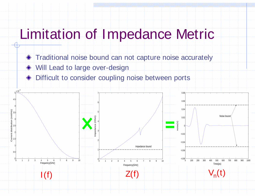
Limitation of Impedance MetricTraditional noise bound can not capture noise accuratelyWill Lead to large over-designDifficult to consider coupling noise between ports
0 1 2 3 4 5 6 7 8 9 100
1
2
3
4
5
6
7
Frequency(GHz)
Imp
ed
an
ce
(O
hm
)
Impedance bound
0 100 200 300 400 500 600 700 800 900 1000−0.08
−0.06
−0.04
−0.02
0
0.02
0.04
0.06
0.08
Time(ps)
no
ise
(V)
Noise bound
0 1 2 3 4 5 6 7 8 9 100
0.5
1
1.5
2
2.5
3
3.5
4
4.5
5x 10
−9
Frequency(GHz)
Cu
rre
nt
dis
trib
utio
n (
mA
/Hz)
I(f) Z(f) Vn(t)
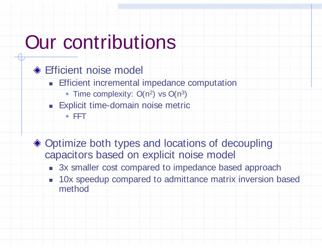
Our contributionsEfficient noise model
Efficient incremental impedance computationTime complexity: O(n2) vs O(n3)
Explicit time-domain noise metricFFT
Optimize both types and locations of decoupling capacitors based on explicit noise model
3x smaller cost compared to impedance based approach10x speedup compared to admittance matrix inversion based method
Outline
IntroductionElectrical modelsIncremental impedance computation and
noise computationOptimization resultsConclusion
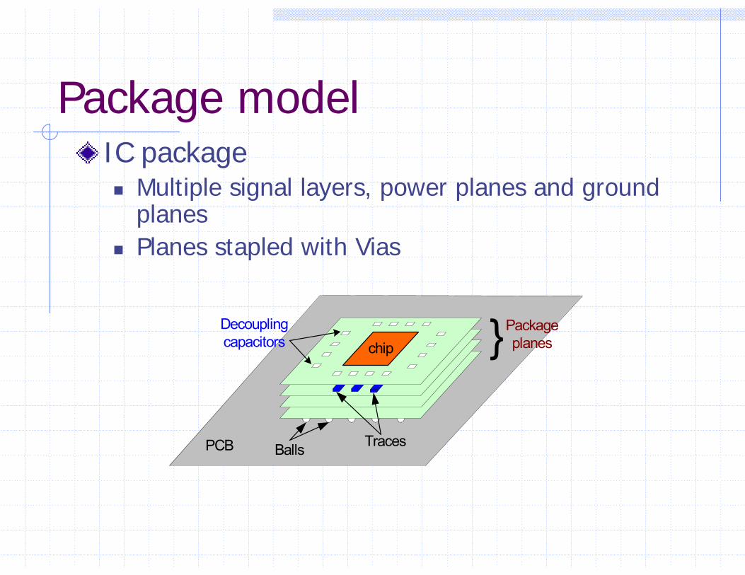
Package modelIC package
Multiple signal layers, power planes and ground planesPlanes stapled with Vias
chipDecoupling capacitors Package
planes
TracesPCB Balls
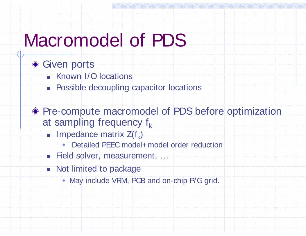
Macromodel of PDSGiven ports
Known I/O locationsPossible decoupling capacitor locations
Pre-compute macromodel of PDS before optimization at sampling frequency fk
Impedance matrix Z(fk)Detailed PEEC model+model order reduction
Field solver, measurement, …Not limited to package
May include VRM, PCB and on-chip P/G grid.
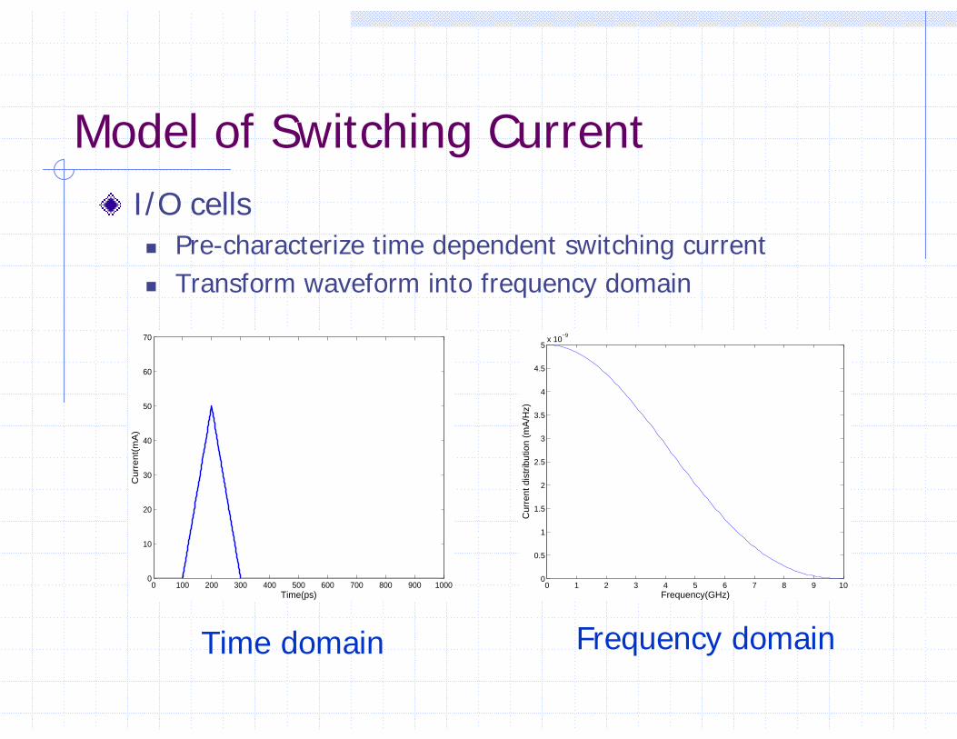
Model of Switching CurrentI/O cells
Pre-characterize time dependent switching currentTransform waveform into frequency domain
0 100 200 300 400 500 600 700 800 900 10000
10
20
30
40
50
60
70
Time(ps)
Cu
rre
nt(
mA
)
0 1 2 3 4 5 6 7 8 9 100
0.5
1
1.5
2
2.5
3
3.5
4
4.5
5x 10
−9
Frequency(GHz)
Cur
rent
dis
trib
utio
n (m
A/H
z)
Time domain Frequency domain
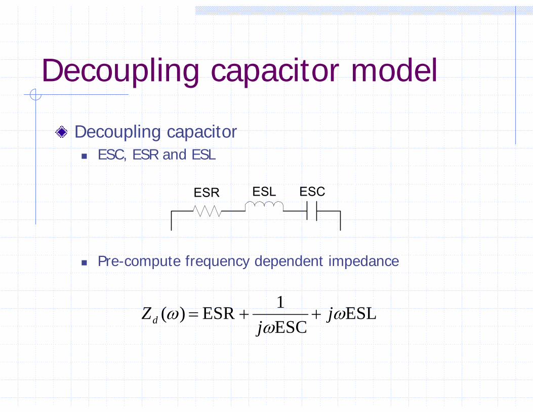
Decoupling capacitor model
Decoupling capacitorESC, ESR and ESL
Pre-compute frequency dependent impedance
ESR ESL ESC
ESLESC1 ESR )( ω
ωω j
jZd ++=

Outline
IntroductionElectrical models Incremental impedance computation and
noise computationOptimization resultsConclusion
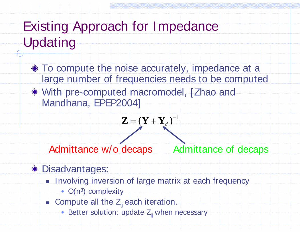
Existing Approach for Impedance Updating
To compute the noise accurately, impedance at a large number of frequencies needs to be computed With pre-computed macromodel, [Zhao and Mandhana, EPEP2004]
Disadvantages:Involving inversion of large matrix at each frequency
O(n3) complexityCompute all the Zij each iteration.
Better solution: update Zij when necessary
1)( −+= dYYZ
Admittance w/o decaps Admittance of decaps
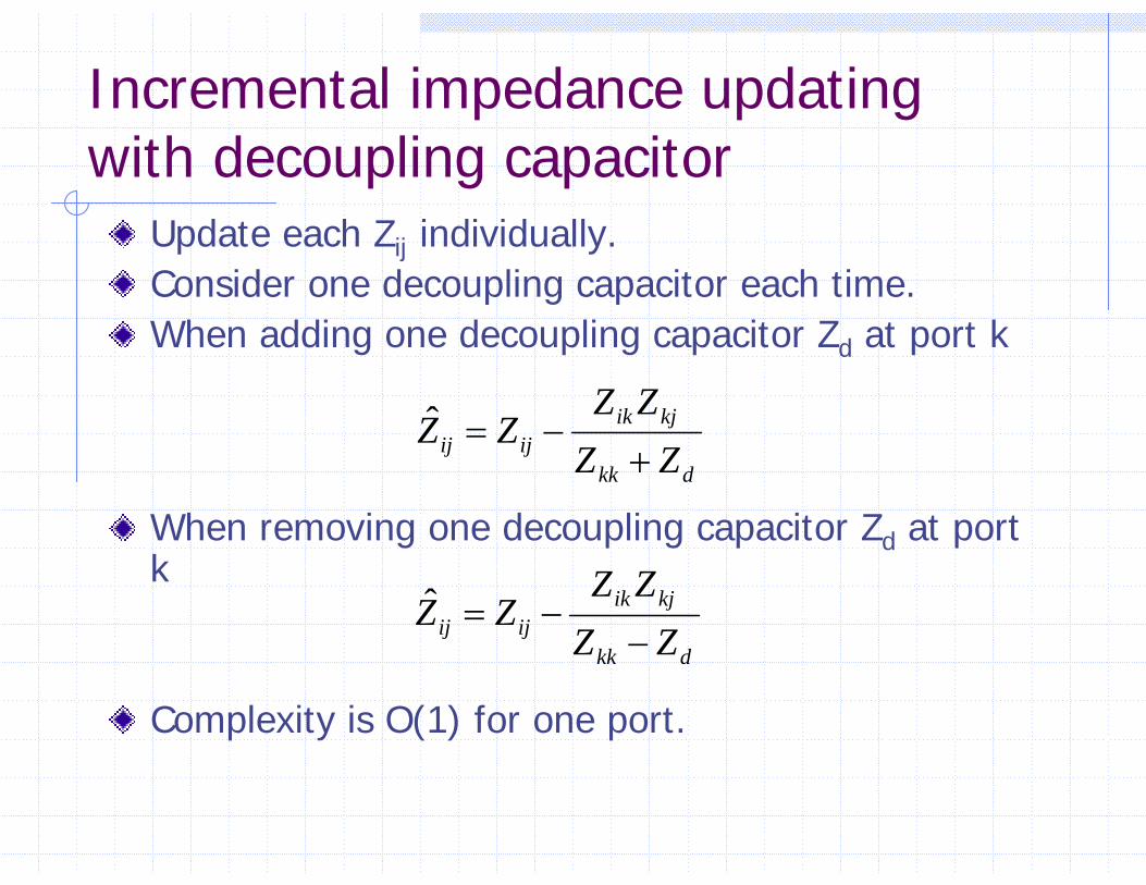
Incremental impedance updating with decoupling capacitor
Update each Zij individually.Consider one decoupling capacitor each time.When adding one decoupling capacitor Zd at port k
When removing one decoupling capacitor Zd at port k
Complexity is O(1) for one port.
dkk
kjikijij ZZ
ZZZZ
+−=ˆ
dkk
kjikijij ZZ
ZZZZ
−−=ˆ
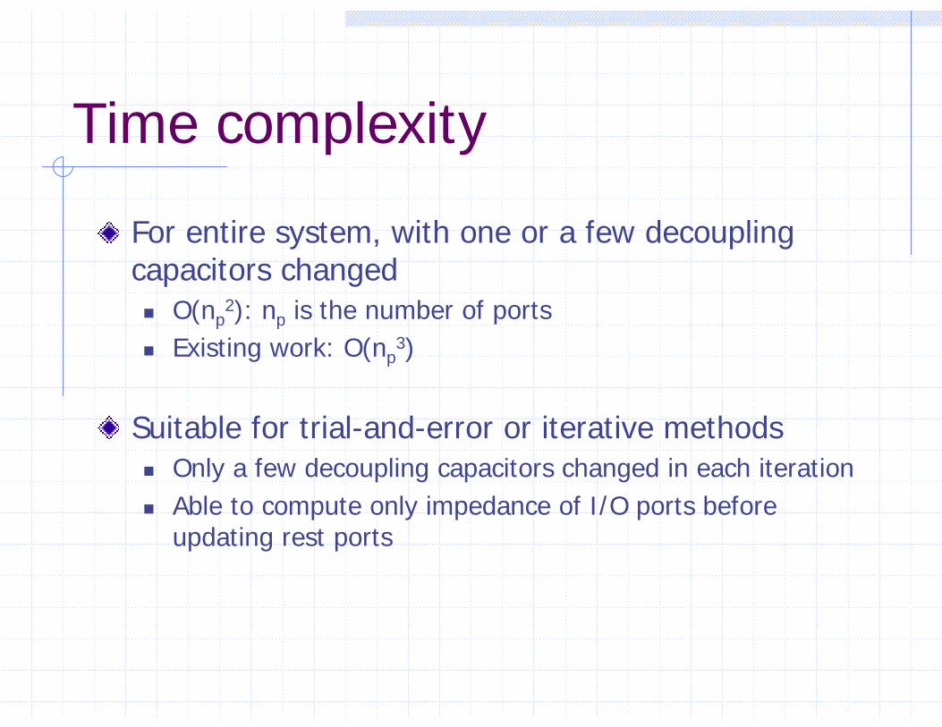
Time complexity
For entire system, with one or a few decoupling capacitors changed
O(np2): np is the number of ports
Existing work: O(np3)
Suitable for trial-and-error or iterative methodsOnly a few decoupling capacitors changed in each iterationAble to compute only impedance of I/O ports before updating rest ports

Noise Calculation
FFT methodsImpedance is computed at a large number of frequenciesFrequency components of noise from port j to port i
Worst case noiseConsider coupling noise from other portsSuperposition
( ) ( ) ( )ij k ij k j kV f Z f I f= •

Efficient General Iterative Optimization Flow
O(nI/O2)
O(np2)
Compute impedance matrix of PDS without decaps
Compute impedance of I/O ports
Noise Computation via FFT
Satisfied?
Change types and locations of decoupling capacitors
N
solution
Compute Impedance of rest ports
Accepted?
Y
Y
N
N

Outline
IntroductionElectrical models Incremental impedance computation and
noise computationOptimization resultsConclusion
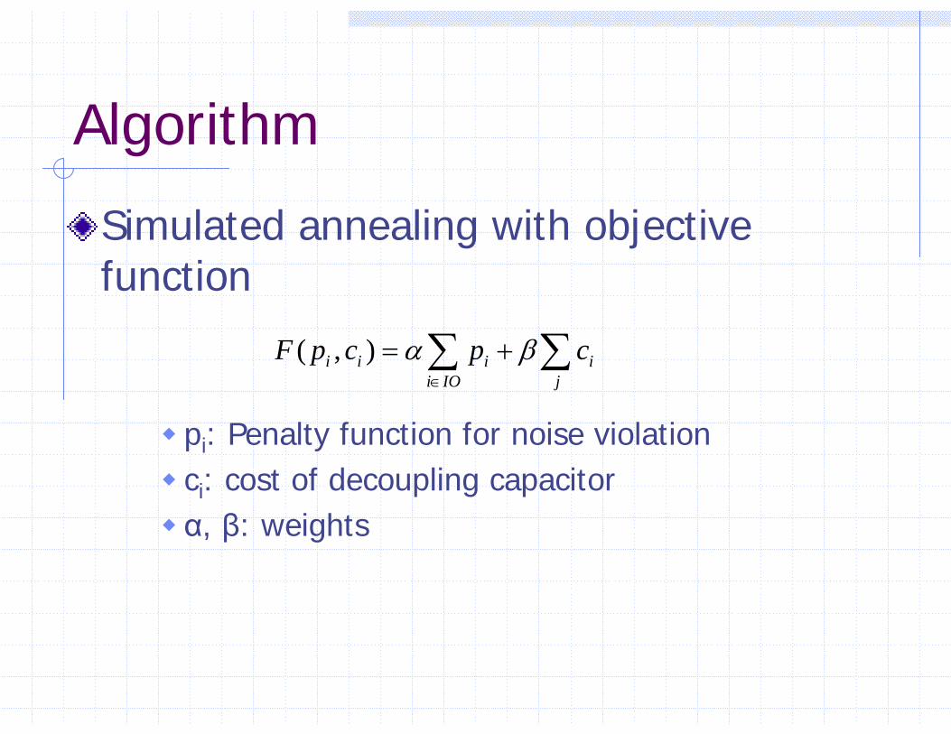
Algorithm
Simulated annealing with objective function
pi: Penalty function for noise violationci: cost of decoupling capacitorα, β: weights
( , )i i i ii IO j
F p c p cα β∈
= +∑ ∑
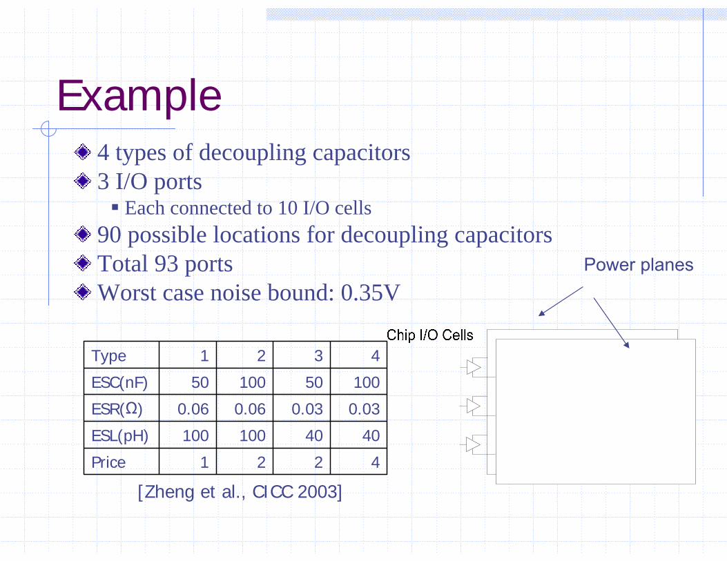
Example
4221Price
4040100100ESL(pH)
0.030.030.060.06ESR(Ω)
1005010050ESC(nF)
4321Type
4 types of decoupling capacitors3 I/O ports
Each connected to 10 I/O cells90 possible locations for decoupling capacitorsTotal 93 portsWorst case noise bound: 0.35V
Power planes
[Zheng et al., CICC 2003]
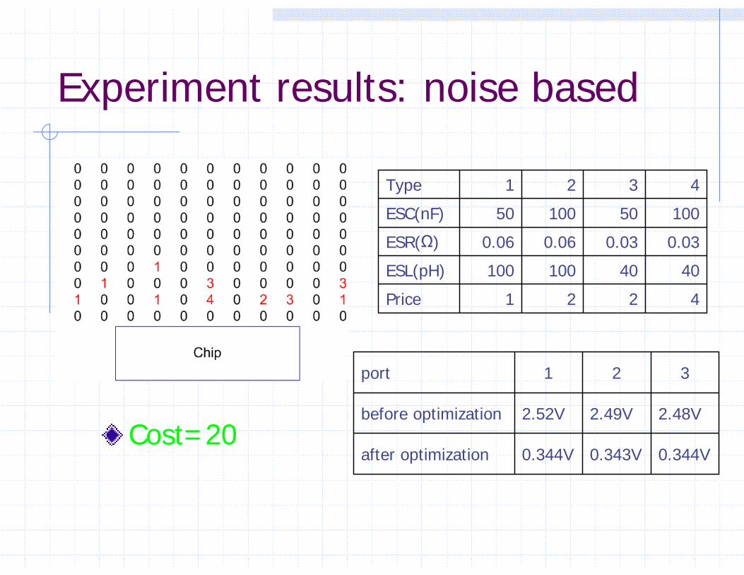
Experiment results: noise based
Cost=200.344V0.343V0.344Vafter optimization
2.48V2.49V2.52Vbefore optimization
321port
4221Price
4040100100ESL(pH)
0.030.030.060.06ESR(Ω)
1005010050ESC(nF)
4321Type
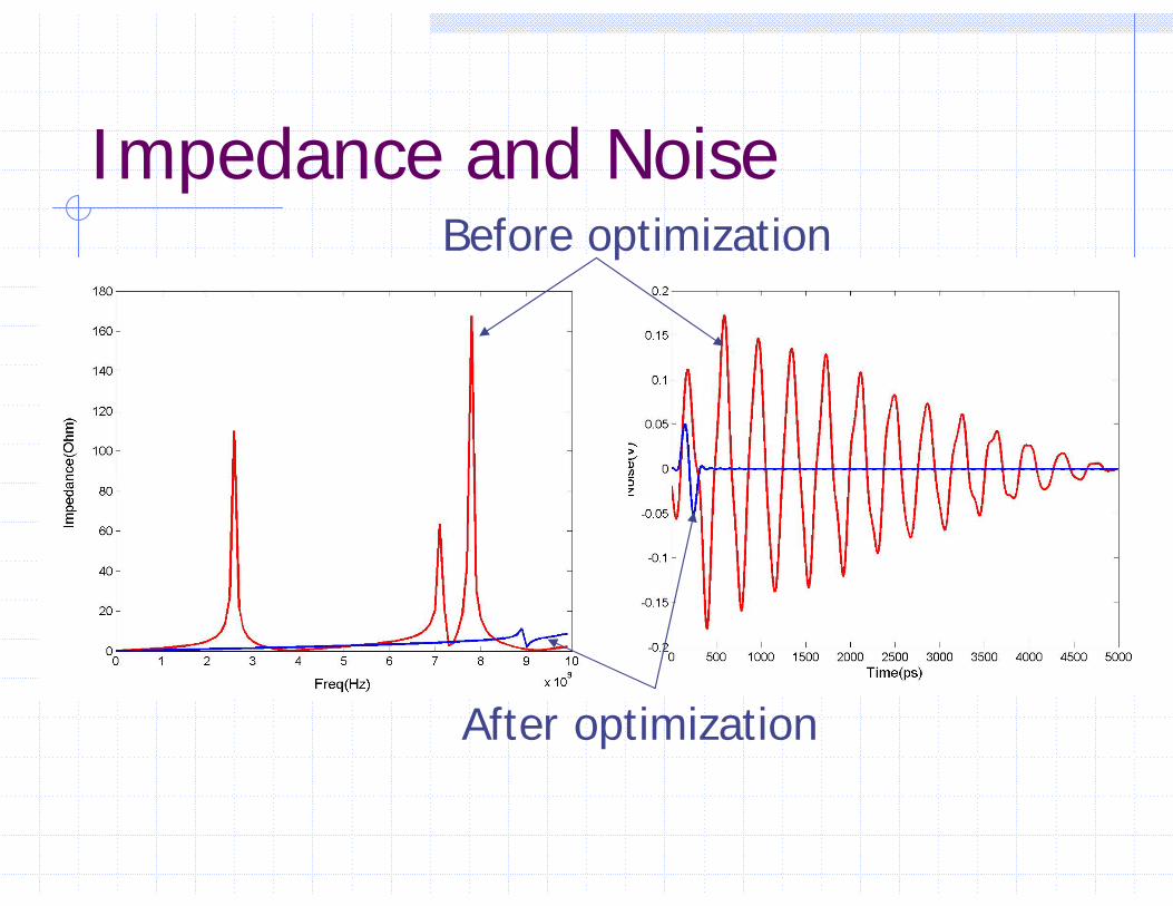
Impedance and NoiseBefore optimization
After optimization
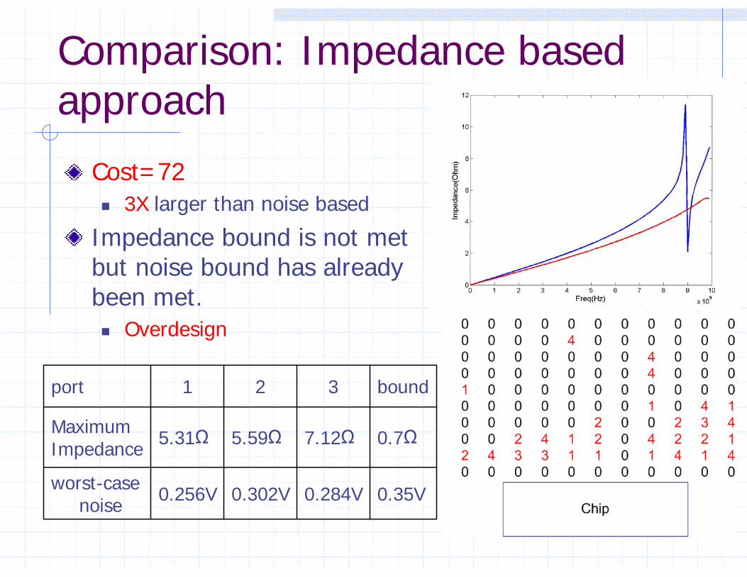
Comparison: Impedance based approach
Cost=723X larger than noise based
Impedance bound is not met but noise bound has already been met.
Overdesign
0.35V0.284V0.302V0.256Vworst-case noise
0.7Ω7.12Ω5.59Ω5.31ΩMaximumImpedance
bound321port
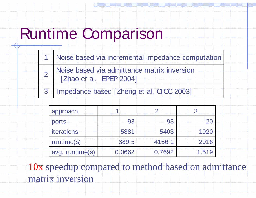
Runtime Comparison
Impedance based [Zheng et al, CICC 2003]3
Noise based via admittance matrix inversion [Zhao et al, EPEP 2004]2
Noise based via incremental impedance computation1
1.5190.76920.0662avg. runtime(s)
29164156.1389.5runtime(s)
192054035881iterations
209393ports
321approach
10x speedup compared to method based on admittance matrix inversion
Conclusion
Proposed efficient noise computation model based on incremental impedance updatingProposed efficient noise driven decoupling capacitor optimization algorithm
3X smaller cost 10x speedup
Demonstrated impedance based approach leads to large overdesign.