Embed Size (px)
Citation preview
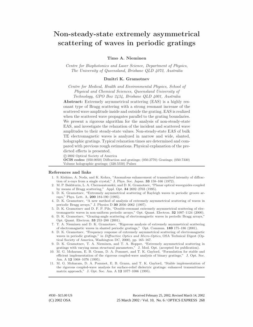
Non-steady-state extremely asymmetrical
scattering of waves in periodic gratings
Timo A. Nieminen
Centre for Biophotonics and Laser Science, Department of Physics,The University of Queensland, Brisbane QLD 4072, Australia
Dmitri K. Gramotnev
Centre for Medical, Health and Environmental Physics, School ofPhysical and Chemical Sciences, Queensland University ofTechnology, GPO Box 2434, Brisbane QLD 4001, Australia
Abstract: Extremely asymmetrical scattering (EAS) is a highly res-onant type of Bragg scattering with a strong resonant increase of thescattered wave amplitude inside and outside the grating. EAS is realizedwhen the scattered wave propagates parallel to the grating boundaries.We present a rigorous algorithm for the analysis of non-steady-stateEAS, and investigate the relaxation of the incident and scattered waveamplitudes to their steady-state values. Non-steady-state EAS of bulkTE electromagnetic waves is analyzed in narrow and wide, slanted,holographic gratings. Typical relaxation times are determined and com-pared with previous rough estimations. Physical explanation of the pre-dicted effects is presented.c© 2002 Optical Society of AmericaOCIS codes: (050.0050) Diffraction and gratings; (050.2770) Gratings; (050.7330)Volume holographic gratings; (320.5550) Pulses
References and links1. S. Kishino, A. Noda, and K. Kohra, “Anomalous enhancement of transmitted intensity of diffrac-tion of x-rays from a single crystal,” J. Phys. Soc. Japan. 33 158–166 (1972).
2. M. P. Bakhturin, L. A. Chernozatonskii, and D. K. Gramotnev, “Planar optical waveguides coupledby means of Bragg scattering,” Appl. Opt. 34 2692–2703 (1995).
3. D. K. Gramotnev, “Extremely asymmetrical scattering of Rayleigh waves in periodic groove ar-rays,” Phys. Lett. A, 200 184-190 (1995).
4. D. K. Gramotnev, “A new method of analysis of extremely asymmetrical scattering of waves inperiodic Bragg arrays,” J. Physics D 30 2056–2062 (1997).
5. D. K. Gramotnev and D. F. P. Pile, “Double-resonant extremely asymmetrical scattering of elec-tromagnetic waves in non-uniform periodic arrays,” Opt. Quant. Electron. 32 1097–1124 (2000).
6. D. K. Gramotnev, “Grazing-angle scattering of electromagnetic waves in periodic Bragg arrays,”Opt. Quant. Electron. 33 253–288 (2001).
7. T. A. Nieminen and D. K. Gramotnev, “Rigorous analysis of extremely asymmetrical scatteringof electromagnetic waves in slanted periodic gratings,” Opt. Commun. 189 175–186 (2001).
8. D. K. Gramotnev, “Frequency response of extremely asymmetrical scattering of electromagneticwaves in periodic gratings,” in Diffractive Optics and Micro-Optics, OSA Technical Digest (Op-tical Society of America, Washington DC, 2000), pp. 165–167.
9. D. K. Gramotnev, T. A. Nieminen, and T. A. Hopper, “Extremely asymmetrical scattering ingratings with varying mean structural parameters,” J. Mod. Opt. (accepted for publication).
10. M. G. Moharam, E. B. Grann, D. A. Pommet, and T. K. Gaylord, “Formulation for stable andefficient implementation of the rigorous coupled-wave analysis of binary gratings,” J. Opt. Soc.Am. A 12 1068–1076 (1995).
11. M. G. Moharam, D. A. Pommet, E. B. Grann, and T. K. Gaylord, “Stable implementation ofthe rigorous coupled-wave analysis for surface-relief dielectric gratings: enhanced transmittancematrix approach,” J. Opt. Soc. Am. A 12 1077–1086 (1995).
(C) 2002 OSA 25 March 2002 / Vol. 10, No. 6 / OPTICS EXPRESS 268#930 - $15.00 US Received February 25, 2002; Revised March 14, 2002
1 Introduction
Extremely asymmetrical scattering (EAS) is a radically new type of Bragg scatteringin slanted, periodic, strip-like wide gratings, when the first diffracted order satisfyingthe Bragg condition (scattered wave) propagates parallel to the front grating bound-ary [1–9]. The main characteristic feature of EAS is the strong resonant increase of thescattered wave amplitude, compared to the amplitude of the incident wave at the frontboundary [1–9]. Other unique features of EAS include additional resonances in non-uniform gratings [5], detuned gratings [8], in wide gratings when the scattered wavepropagates at a grazing angle with respect to the boundaries [6], and the unusuallystrong sensitivity of EAS to small variations of mean structural parameters at the grat-ing boundaries [9]. The additional resonances may result in amplitudes of the scatteredand incident waves in the grating that can be dozens or even hundreds of times largerthan that of the incident wave at the front boundary [5–9].One of the main physical reasons for all these unusual features of EAS is the diffrac-
tional divergence of the scattered wave inside and outside the grating [2–6, 9]. Indeed,the scattered wave results from scattering of the incident wave inside the grating, andpropagates parallel to the grating. Thus, it is equivalent to a beam located within thegrating, of an aperture equal to the grating width. Such a beam will diverge outside thegrating due to diffraction. Therefore, steady-state EAS is formed by the two physicaleffects – scattering and diffractional divergence. Based on the equilibrium between theseprocesses, an approximate analytical method of analysis of EAS, applicable to all typesof waves, has been developed [2–4,6, 8, 9].A reasonable question is which of the EAS resonances are practically achievable?
Any resonance is characterized by a time of relaxation, and if this time is too large,the corresponding resonance cannot be achieved in practice. In the case of EAS, largerelaxation times may result in excessively large apertures of the incident beam beingrequired for the steady-state regime to be realized [4]. It is obvious that knowledgeof relaxation times and relaxation (non-steady-state) processes during EAS is essentialfor the successful development of practical applications of this highly unusual type ofscattering.Until recently, only estimates of relaxation times for EAS in uniform gratings have
been made [2–4]. The analysis was based on physical assumptions and speculations [3,4], rather than direct treatment of non-steady-state regime of EAS. Simple analyticalequations for the relaxation times were derived [3, 4]. However, the accuracy of theseequations is questionable, since their derivation did not take into account re-scatteringprocesses in the grating. Moreover, these equations are not applicable in the presenceof the additional resonances [5, 6, 8].Therefore, the first aim of this paper is to present an efficient numerical algorithm
for the rigorous analysis of non-steady-state EAS of bulk electromagnetic waves in wideuniform and non-uniform holographic gratings. The second aim is to investigate non-steady-state EAS and accurately determine relaxation times in narrow and wide uniformperiodic gratings. In particular, amplitudes of the incident wave (0th diffracted order)and scattered wave (+1 diffracted order) inside and outside the grating will be deter-mined as functions of time and coordinates after the incident wave is “switched on.”
2 Structure and methods of analysis
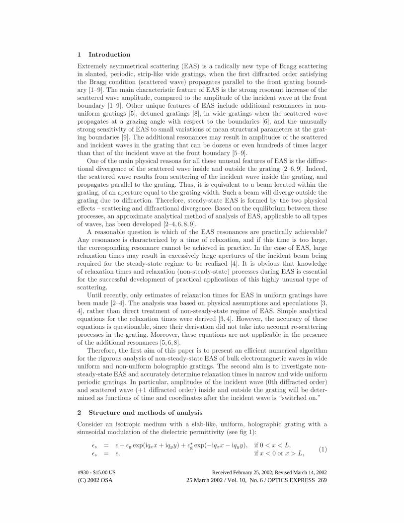
Consider an isotropic medium with a slab-like, uniform, holographic grating with asinusoidal modulation of the dielectric permittivity (see fig 1):
εs = ε+ εg exp(iqxx+ iqyy) + ε�g exp(−iqxx − iqyy), if 0 < x < L,
εs = ε, if x < 0 or x > L,(1)
(C) 2002 OSA 25 March 2002 / Vol. 10, No. 6 / OPTICS EXPRESS 269#930 - $15.00 US Received February 25, 2002; Revised March 14, 2002
where L is the grating width, εg is the grating amplitude, the mean dielectric permittiv-ity ε is the same inside and outside the grating, qx and qy are the x and y componentsof the reciprocal lattice vector q, q = 2π/Λ, Λ is the period of the grating, and thecoordinate system is shown in figure 1. There is no dissipation in the medium (ε is realand positive), and the structure is infinite along the y and z axes.
Λ
ε ε, εg
θ 0
k
k
1
0
(
(
ω
ω
0
0
)
)
y
x
q
L
ε
Fig. 1. The geometry of EAS in a slanted periodic grating.
Non-steady-state EAS in this structure occurs when the incident wave is switched onat some moment of time. Then, both the incident and scattered wave amplitudes insideand outside the grating evolve in time and gradually relax to their steady-state valuesat t = +∞. This occurs when the incident pulse, having an infinite aperture along they and z axes, is the product of a sinusoid and a step function of time.However, the numerical analysis of this infinitely long (in time) pulse is inconve-
nient, since its Fourier transform contains a δ-function. Therefore, in order to calculatenon-steady-state amplitudes of the incident and scattered waves in the structure atan arbitrary moment of time t = t0, we consider a rectangular (in time) sinusoidalincident pulse of time length 2t0, amplitude E00, and angle of incidence θ0 (fig. 1),which has a simple analytical Fourier transform. We also assume that the incident pulseis switched on instantaneously (with the amplitude E00) everywhere in the grating.That is, we ignore the process of propagation of the pulse through the grating. Thisassumption allows a substantial reduction in computational time. It is correct only ifthe time t0, at which non-steady-state amplitudes are calculated, is significantly largerthan tg = (L/ cos θ0)/(cε−1/2) – the time of propagation of the incident pulse across thegrating. We will see below that this condition is satisfied (for most times) since typicalrelaxation times τ � tg.Thus, at t = 0, the front of the pulse is at the rear grating boundary, i.e. the incident
field is zero behind the grating (at x > L). This means that if the angle of incidenceθ0 �= 0 (fig. 1), then the amplitude of the incident pulse is not constant along a wavefront. Therefore, the incident pulse experiences diffractional divergence, and the spatialFourier transform should be used. However, this divergence can be ignored in our furtherconsiderations, since it may be significant only within several wavelengths near the frontof the pulse, i.e. for times ≈ 10−14 s or smaller (this is the time for the pulse to travel adistance of a few wavelengths). This time is several orders of magnitude less than typicalrelaxation times (see below). Therefore, only for very short time intervals after switchingan incident pulse on can noticeable errors result from the above approximations.The frequency spectrum of this input is determined from its analytical Fourier trans-
form. As a result, the incident pulse is represented by a superposition of an infinite
(C) 2002 OSA 25 March 2002 / Vol. 10, No. 6 / OPTICS EXPRESS 270#930 - $15.00 US Received February 25, 2002; Revised March 14, 2002
number of plane waves having different frequencies and amplitudes, all incident at θ0.Note that the spectrum is the incident pulse depends on the pulse width 2t0, and isdifferent for every time t0 at which we calculate the fields. The steady-state response ofthe grating to each plane wave is determined by means of the rigorous theory of steady-state EAS [7], based on the enhanced T-matrix algorithm [10, 11], or the approximatetheory [8] (if applicable). Thus the frequency spectrum of the incident and scatteredwaves inside and outside the grating is obtained, and their amplitudes as functions ofthe x-coordinate at any moment time can be found using the inverse Fourier transform.Due to the geometry of the problem, the non-steady-state incident and scattered waveamplitudes do not depend on the y-coordinate.Note that the inverse Fourier transform is taken at t = t0, i.e. at the middle of the
incident pulse, in order to minimize numerical errors. The inverse Fourier transform isfound by direct integration, to allow a non-uniform set of frequency points to be used.The rapid variation of the frequency spectra at certain points, and the wide frequencyspectrum of the input for small t0 make it infeasible to use the fast Fourier transform.The calculations are carried out separately for each moment of time. Therefore, there isno accumulation of numerical errors, and the errors that are noticeable at small times≈ 10−14 s (see above) disappear at larger times.This approach is directly applicable for all shapes of the incident pulse, as well as
for an incident beam of finite aperture. However, for beams of finite aperture, we shouldalso use the spatial Fourier integral.Since the approximate theory is directly applicable for all types of waves (including
surface and guided waves in periodic groove arrays [2, 3, 9]), the developed approachto non-steady-state scattering is also applicable for all types of waves (if used togetherwith the approximate theory).
3 Numerical Results
Using the described numerical algorithm, non-steady-state EAS of bulk TE electromag-netic waves in uniform holographic gratings given by eqn (1) has been analyzed. Thegrating parameters are as follows: ε = 5, εg = 5 × 10⁻³, θ0 = 45◦, and the wavelengthin vacuum (corresponding to the central frequency ω0 of the spectrum of the incidentpulse) λ0 = 1µm. The Bragg condition is assumed to be satisfied precisely for the firstdiffracted order at ω = ω0:
k1(ω0) = k0(ω0)− q, (2)
where k0(ω) are the frequency dependent wave vectors of the plane waves in the Fourierintegral of the incident pulse, k1(ω) are the wave vectors of the corresponding firstdiffracted orders (scattered waves), k1(ω0) = k0(ω0) = ω0ε
1/2/c, k1(ω0) is parallel tothe grating boundaries (fig. 1), and c is the speed of light. Note that if ω �= ω0, k1(ω)is not parallel to the grating boundaries [8].Typical relaxation of amplitudes of the scattered wave (+1 diffracted order) and
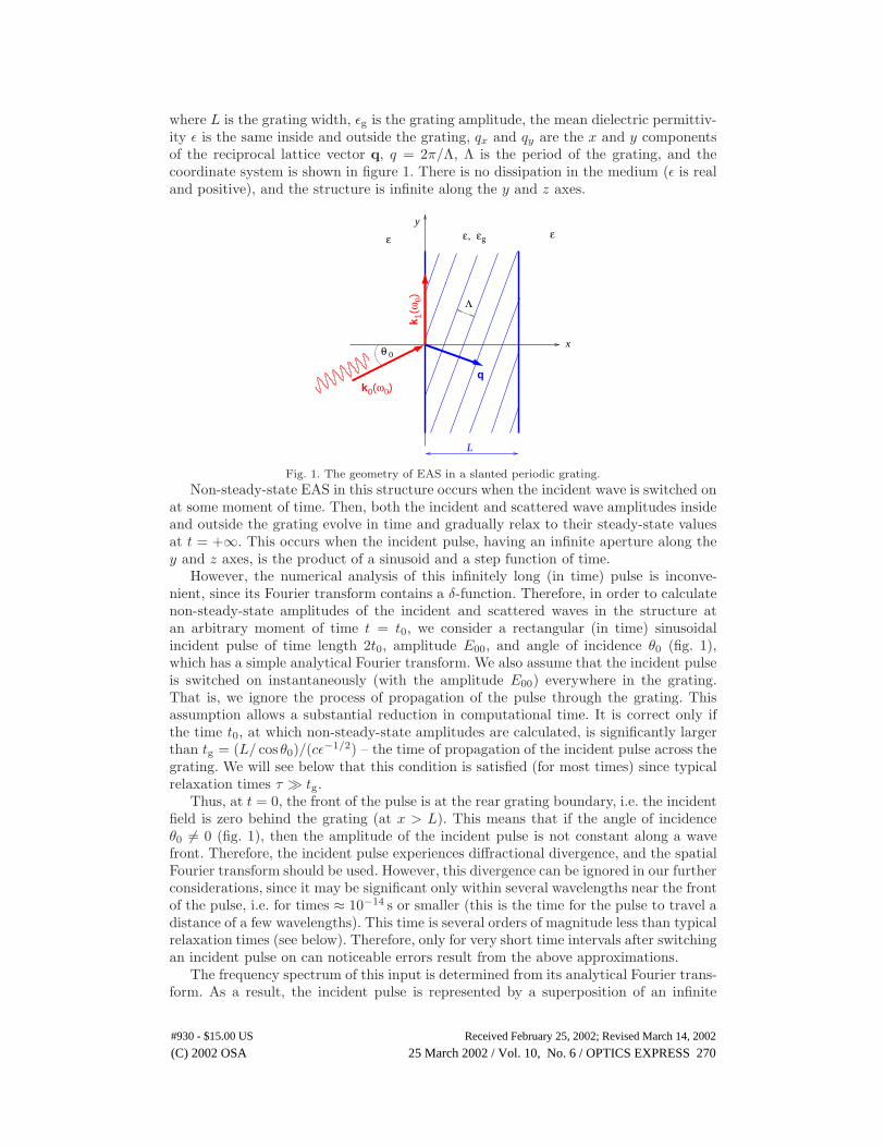
incident wave (0th diffracted order) over time inside and outside the gratings of widthsL = 10µm, 28µm, and 80µm is shown in the animations in fig. 2. The time dependenciesof non-steady-state amplitudes of the scattered wave (+1 diffracted order) at x = 0,L/2, and L, and the transmitted wave (0th diffracted order at x = L) are shown infig. 3 for the same grating widths. Note that L = 28µm is approximately equal to thecritical width Lc [5]. Physically, Lc/2 is the distance within which the scattered wavecan be spread across the grating by means of the diffractional divergence, before beingre-scattered by the grating [5]. All the curves in figures 2 and 3 can equally be regardedas approximate or rigorous, since both the theories in the considered structure givepractically indistinguishable results [7].
(C) 2002 OSA 25 March 2002 / Vol. 10, No. 6 / OPTICS EXPRESS 271#930 - $15.00 US Received February 25, 2002; Revised March 14, 2002
(a) (b) (c)
−10 −5 0 5 10 15 200
0.2
0.4
0.6
0.8
1
x (µm)
Inci
dent
wav
e
t = 7.36e−12 s
−10 −5 0 5 10 15 200
5
10
15
20
25
x (µm)
Sca
ttere
d w
ave
−20 −10 0 10 20 30 400
0.2
0.4
0.6
0.8
1
x (µm)
Inci
dent
wav
e
t = 7.36e−12 s
−20 −10 0 10 20 30 400
5
10
15
x (µm)
Sca
ttere
d w
ave
−20 0 20 40 60 80 1000
0.2
0.4
0.6
0.8
1
x (µm)
Inci
dent
wav
e
t = 7.36e−12 s
−20 0 20 40 60 80 1000
5
10
15
x (µm)
Sca
ttere
d w
ave
[animated gif, 469kb] [animated gif, 543kb] [animated gif, 628kb]
Fig. 2. Animations showing the approach of amplitudes of the scattered (bottomgraphs) and incident (top graphs) waves to the steady-state solutions (light lines).The grating widths are (a) L = 10µm, (b) L = 28µm ≈ Lc, and (c) L = 80µm.The vertical dotted lines show the grating boundaries.
10 10 10 10−13 −13 −13 −13
10 10 10 10−9−11 −11 −9 −11 −9 −11 −9
10 10 10 10
0
5
10
(1,2)(3)
(2)
(1)
(2)
(1)
(3)
(3)
15
20
25
0
4
8
12
0
2
4
6
8
10
12
of
dif
frac
ted
ord
ers
Rel
ativ
e am
plit
ud
es
Time (s)
1
(c) (d)(b)(a)4
0
0.2
0.4
0.6
0.8
1
(iii)
(i)
(ii)
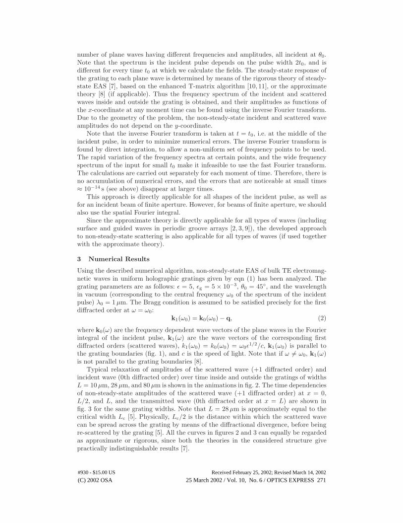
Fig. 3. The time dependencies of normalized non-steady-state amplitudes of (a–c)the first diffracted order (scattered wave) |E1/E00|, and (d) the zeroth diffractedorder (transmitted wave) |E0(x = L)/E00|. The grating widths are L = 10 µm ((a)and curve (i) in (d)), L = 28 µm ≈ Lc ((b) and curve (ii) in (d)), and L = 80 µm((c) and curve (iii) in (d)). The scattered wave amplitudes (a–c) are shown at (1)the front boundary (x = 0), (2) the rear boundary (x = L), and (3) the middle ofthe grating (x = L/2).
If L < Lc, then the relaxation at the front and rear grating boundaries occurspractically simultaneously (see figures 2(a) and 3(a)). In the middle of the grating,the scattered wave amplitude grows slightly faster at small t. This is due to energylosses from the scattered wave, caused by diffractional divergence of the wave near theboundaries (the edges of the scattered beam). This effect becomes more obvious withincreasing grating width, and is especially strong if L ≈ Lc (fig. 3(b)). This is becausethe effect of the diffractional divergence in the middle of the grating (in the middleof the beam) becomes weaker with increasing grating width (i.e. beam aperture). Atthe same time, at the edges of the beam (at the grating boundaries) the divergence isstrong, resulting in a significant reduction of the rate of change of the non-steady-statescattered wave amplitudes (compare curves (1) and (2) with curve (3) in fig. 3(b)).However, in wide gratings (with L > Lc), the relaxation occurs first near the frontboundary, and then the steady-state scattered wave amplitudes start spreading towardsthe rear boundary (fig. 2(c)). Therefore, the relaxation process in the middle of thegrating and especially at the rear boundary tends to slow down compared to that nearthe front boundary – compare curves (1) and (2) in figs. 3(b,c).The relaxation near the front boundary takes place more or less smoothly, except
for some not very significant oscillations in wide gratings near the end of the relaxation
(C) 2002 OSA 25 March 2002 / Vol. 10, No. 6 / OPTICS EXPRESS 272#930 - $15.00 US Received February 25, 2002; Revised March 14, 2002
process (curves (1) in figs. 3(a–c)). The same happens in the middle of the grating andat the rear boundary in narrow gratings (L < Lc). However, if L ≥ Lc, the relaxationcurves in the middle of the grating and at the rear boundary display a complex andunusual behavior at small and large time intervals (see curves (2) and (3) in figs. 3(b,c)).The unusual and complex character of relaxation processes in wide gratings is es-
pecially obvious from the time dependencies of non-steady-state incident (transmitted)wave amplitude at the rear grating boundary (figs. 2(c), 3(d)). In wide gratings, thesedependencies are characterized by significant oscillations with minima that are close tozero – see fig. 2(c) and curve (iii) in fig. 3(d). The typical number of these oscillationsincreases with increasing grating width (compare curves (ii) and (iii) in fig. 3(d)). Theminima in these oscillations tend to zero with increasing L. When the amplitude of thetransmitted wave at the rear grating boundary is close to zero, almost all energy of theincident wave is transferred to the scattered wave. In wide gratings this may happenseveral times during the relaxation process (figs. 2(c), 3(d)).The relaxation times at the grating boundaries and at x = L/2, determined as the
times at which the amplitudes reach (1− 1/e) of their steady-state values, are:L τ |x=0 τ |x=L/2 τ |x=L
10µm 4× 10⁻¹¹ s 4× 10⁻¹¹ s 4× 10⁻¹¹ s28µm 6× 10⁻¹² s 1.7× 10⁻¹² s 2.4× 10⁻¹¹ s80µm 7.4× 10⁻¹² s 1.2× 10⁻¹¹ s 3.4× 10⁻¹¹ s
The relaxation times for narrow gratings, determined by means of the developed algo-rithm, are about three times smaller than those previously estimated [4]. The significantoverestimation of relaxation times in paper [4] is due to not taking into account the ef-fects of re-scattering of the scattered wave in the grating. Re-scattering reduces thetransmitted wave amplitude during the relaxation process (fig. 3(d)). Thus, the energyflow into the scattered wave is increased, and the relaxation times are reduced (for moredetailed discussion of re-scattering see [5]).During the process of relaxation, the scattered wave propagates a particular distance
along the y-axis. Therefore, the relaxation times determine critical apertures lc (alongthe y-axis) of the incident beam, that are required for steady-state EAS to be achieved(see also [4]). For example, for fig. 3(a) (with the largest values of τ), the critical apertureof the incident beam is lc = cτε−1/2 cos θ0 ≈ 0.4 cm, which does not present any problemin practice.
4 Conclusions
This paper has developed an efficient numerical algorithm for the approximate and rig-orous numerical analysis of non-steady-state EAS of waves in uniform slanted gratings.An unusual type of relaxation with strong oscillations of the incident and scattered waveamplitudes has been predicted for gratings wider than the critical width.If used in conjunction with the approximate theory of steady-state EAS [2–4,8], the
developed algorithm is immediately applicable for the analysis of non-steady-state EASof all types of waves, including surface and guided modes in periodic groove arrays.Typical relaxation times have been calculated for narrow and wide gratings. It has
been shown that these times are significantly smaller than previous estimates [3,4]. Thecorresponding critical apertures of the incident beam that are required for achievingsteady-state EAS have also been determined. The obtained results demonstrate thatsteady-state EAS can readily be achieved in practice for reasonable beam apertures andnot very long gratings.
(C) 2002 OSA 25 March 2002 / Vol. 10, No. 6 / OPTICS EXPRESS 273#930 - $15.00 US Received February 25, 2002; Revised March 14, 2002