Embed Size (px)
Citation preview
1
Nonlinear Compensation Assessment in Few-modeFibers via Phase-Conjugated Twin Waves
J. S. Tavares, L. M. Pessoa and H. M. Salgado
Abstract—In this paper we further explore the concept ofphase-conjugated twin waves (PCTW) for nonlinear cancella-tion in space-division multiplexed (SDM) systems. Previously,we demonstrated that the PCTW technique can successfullyprovide nonlinear cancellation in SDM systems. In this paper, weinvestigate the cases where two and four spatial modes are co-propagating in a multimode fiber, considering three link lengths(1000 km, 3200 km and 8000 km). Weak and strong-couplingregimes are also evaluated. Our numerical simulation resultsshow an average performance improvement >10 dB after a 1000km transmission link.
Index Terms—Fiber nonlinearity, multimode fiber, phase-conjugated twin waves, space-division multiplexing.
I. INTRODUCTION
W ITH the exponential growth of capacity demand ver-ified in the last few decades, the nonlinear Shannon
limit is rapidly being approached [1], [2], [3], [4], [5]. Tokeep up with the capacity requirements, researchers haveexplored the available physical dimensions in optical fibers,namely time, phase, frequency and polarization. In order todelay the approaching capacity crunch of single-mode fibersthere have been extensive studies that rely on multimodeor multicore fibers, which allow multiplexing over differ-ent spatial modes of the same fiber by employing space-division multiplexing (SDM) [5]. However, alike single-modefiber based modern telecommunication systems, the nonlinearpenalties will eventually become the ultimate limiting factorin SDM systems, resulting from crosstalk effects in multimodeor multicore fibers, which generate intramodal and intermodalnonlinearities. Fiber-optic communication systems are largelylimited in capacity and reach by fiber Kerr nonlinearity, whichleads to distortion when the signal power is increased toachieve adequate signal-to-noise ratio. To overcome this limit,there have been proposed several nonlinearity compensationtechniques, such as digital back-propagation (DBP) [6] andmid-link optical phase conjugation (ML-PC) [7]. However,ML-PC requires the transmission link to be modified toinclude a phase conjugator in the middle of the link, whichis impractical, whereas DBP based schemes are known to becomputationally complex to implement, even when the inter-channel nonlinearities are known to the receiver [8]. Recently,it has been demonstrated that the phase-conjugated twin waves
This work was supported by FCT - Fundacao para a Ciencia e Tecnologia(Portuguese Foundation for Science and Technology) with the PhD grantPD/BD/113821/2015.
The authors are with INESC TEC and Faculty of Engineering,University of Porto, Porto, Portugal (e-mail: [email protected];[email protected]; [email protected]).
Optical fiber transmission link
SSMF
PCTW Transmitter PCTW Receiver
OA
CoherentSuperposition
Time
Ay = Ax*
Ax
APCTW
Nonlinear propagation
x Nspan
AxRX + (Ay
RX)*
Fig. 1. Single-mode PCTW transmission link diagram.
(PCTW) technique can yield a reduction of nonlinear andlinear distortions in single-mode fibers by about 8.5 dB and3 dB, respectively [9]. Also, it has been suggested that theconcept of PCTW can be further extended by using an or-thogonal dimension rather than the orthogonal polarization totransmit the complex conjugate (e.g. space). Additionally, thesame can be applied to vector waves, where the signal and itsconjugated twin are PDM (polarization-division multiplexed)signals (consisting of two independent polarization compo-nents), propagating on orthogonal dimensions (e.g. space) [9],[10].
In a previous work we proposed three multimode PCTWscenarios, that were based on PDM-wise and mode-wise ap-proaches [11]. Our numerical simulations showed that PCTWcan successfully be used for nonlinear mitigation in SDMsystems as well. Moreover, the PDM-wise approach providedbetter results, yielding a performance improvement of ∼10 dB,when compared with the single-mode PCTW case.
In this work we continue exploring nonlinearity mitigationin SDM systems by employing the PCTW technique. Specifi-cally, we assessed the impact on system performance when co-propagating two and four spatial modes, in the weak and strongcoupling regimes. Furthermore, the impact of transmissionlength was also assessed.
The remainder of this paper is organized as follows: inSection II we first describe the concept of PCTW. In Sec-tion III we describe the multimode PCTW configurationswhich were assessed. Section IV comprises the numerical sim-ulation model including simulation parameters. In Section Vthe obtained numerical simulation results are presented anddiscussed. Lastly, the final conclusions are given in Section VI.
II. SINGLE-MODE PCTW
PCTW-based transmission in single-mode fibers has beenpreviously proposed [9]. This technique consists of propa-gating a PDM optical signal, where one of the orthogonalpolarization components is the complex conjugate of the other,as depicted in Fig. 1. At the receiver side, the nonlinear distor-tions are cancelled to first order by coherently superimposingthe received twin waves. It has been proved that the nonlinear
2
TABLE IMULTIMODE PCTW CONFIGURATIONS.
2 Spatial Modes 4 Spatial Modes
LP01Time
Ay = Ax*
Ax
APCTW
Time
Ay = Ax*
Ax
APCTW
LP11Time
By = Bx*
Bx
BPCTW
Time
By = Bx*
Bx
BPCTW
LP02 -Time
Cy = Cx*
Cx
CPCTW
LP21 -Time
Dy = Dx*
Dx
DPCTW
distortions experienced by a pair of mutually PCTWs areanti-correlated, which leads to the first-order cancellationof nonlinear interactions upon coherently superimposing thereceived signals [9]. This technique requires a symmetricdispersion map, which could be readily applied in a dynamicoptical network environment, through the employment ofelectronic dispersion pre-compensation at the transmitter. Thistechnique has the potential to reduce the overall link costs,specially in applications such as ultralong-haul transmissionand transoceanic optical links, since it allows a reduction ofthe number of transceivers by 50%. On the downside, withthis technique spectral efficiency is traded for transmissionperformance [9].
The nonlinear propagation in a single-mode fiber can bedescribed by the well-known Manakov-PMD equations [12],[13], [14], as follows:
∂APCTW
∂z+iβ22
∂2APCTW
∂t2= i
8
9γ(|Ax|2 + |Ay|2
)APCTW, (1)
where β2 is the group velocity dispersion (GVD), γ is theKerr nonlinear parameter. The PDM signal containing the twinwave is given by
APCTW = (Ax, Ay)T , (2)
consisting of {Ax = A
Ay = A∗x.(3)
At the receiver side, the original signal is recovered withoutnonlinear distortions (to first order) after coherent superposi-tion of the received signals [9], by employing
ARXx + (ARXy )∗ = 2A. (4)
Optical fiber transmission linkMultimode PCTWTransmitter
Multimode PCTWReceiver
Nonlinear propagation
SI-MMF
NF = 5 dB
x Nspan
EDFA
CoherentSuperposition
Lspan
AxRX + (Ay
RX)*
BxRX + (By
RX)*(...)
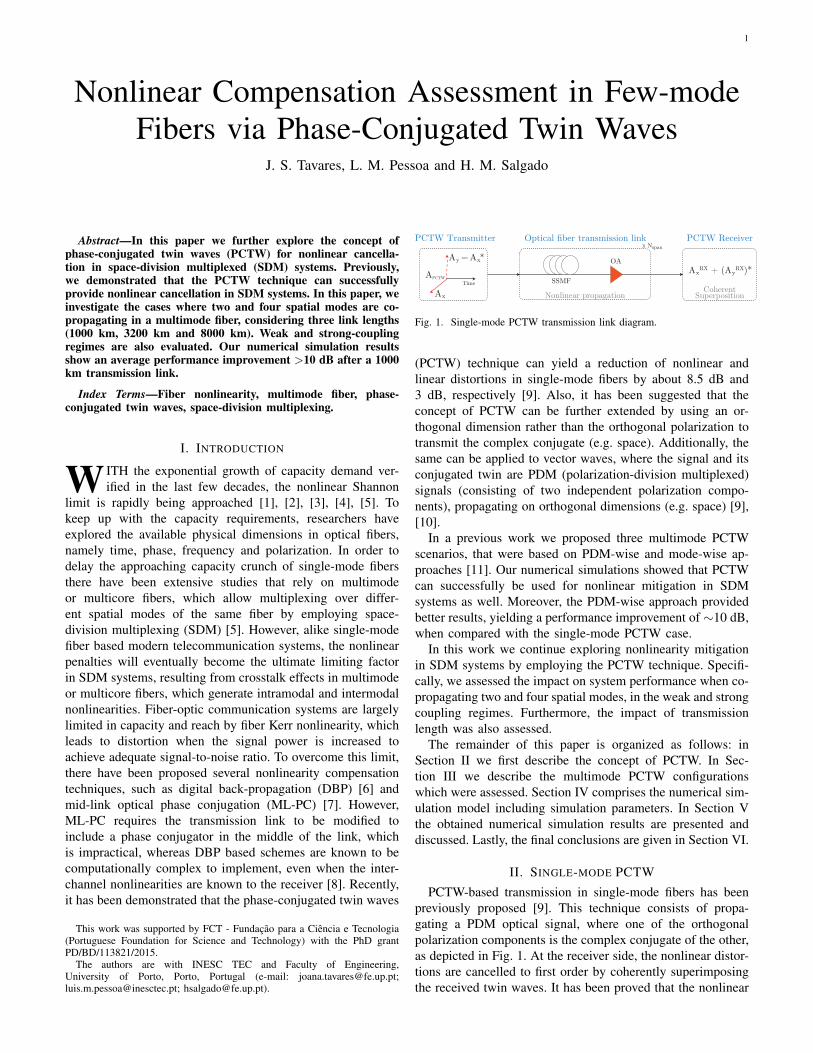
Fig. 2. Multimode PCTW transmission link diagram.
III. MULTIMODE PCTWTable I shows the investigated multimode PCTW config-
urations, following a PDM-wise approach [11], where eachpair of PCTWs is propagated on a single spatial mode anddifferent pairs are sent on distinct spatial modes. Here, weinvestigate the case considering two spatial modes (i.e. LP01and LP11) and four spatial modes (i.e. LP01, LP11, LP02and LP21). At the receiver side the received twin waves arecoherently super-positioned accordingly to each spatial mode,as shown in Fig. 2. However, Eq. (1) cannot be used to describenonlinear propagation in multimode fibers since it does notinclude the intermodal nonlinear effects. An extension of thestandard Manakov equation (SMF based) to multimode fiberswas proposed and evaluated in [15], by assuming that the stateof polarization of each spatial mode evolves randomly andindependently from the other modes. This equation governspropagation of arbitrarily polarized light in the spatial modes,and includes all nonlinear effects (intramodal as in SMF aswell as intermodal nonlinearities among various fiber spatialmodes), random polarization birefringence, chromatic disper-sion and fiber losses within each spatial mode. Moreover,the authors derived a set of equations regarding the weakand strong-coupling regimes. In general, coupling strengthbetween spatial modes can vary for different mode pairs. Forinstance, the LP11a and LP11b spatial modes are stronglycoupled due to its degenerated nature, while the modes LP01and LP11 are weakly coupled [16]. However, in this workthe two coupling regimes represent two extreme cases forpractical systems, where in the weak-coupling regime thelinear coupling between spatial modes is disregarded, whilein the strong coupling regime it is assumed that all modes arestrongly coupled.
In the weak-coupling regime [15], the nonlinear propagationfor the pth mode is given by:
∂Ap∂z
+ 〈δβ0p〉Ap + 〈δβ1p〉∂Ap∂t
+ iβ2p2
∂2Ap∂t2
= iγ
fpppp 8
9|Ap|2 +
∑m 6=p
fmmpp4
3|Am|2
Ap, (5)
where γ is the Kerr nonlinear parameter, 〈δβ0p〉 is the propa-gation constant, 〈δβ1p〉 is the DMGD and β2p is the GVD. Thenonlinear coefficient flmnp provides a relative weight amongthe nonlinear terms between the spatial modes and is definedby:
flmnp =Aeff
(IlImInIp)1/2
∫∫F ∗l FmFnF
∗p dx dy, (6)
where Il, Im, In and Ip represent the constants of normaliza-tion of the modal fields Fl, Fm, Fn and Fp, where the indices
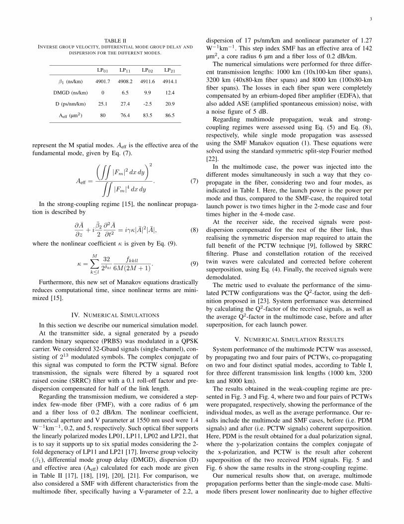
3
TABLE IIINVERSE GROUP VELOCITY, DIFFERENTIAL MODE GROUP DELAY AND
DISPERSION FOR THE DIFFERENT MODES.
LP01 LP11 LP02 LP21
β1 (ns/km) 4901.7 4908.2 4911.6 4914.1
DMGD (ns/km) 0 6.5 9.9 12.4
D (ps/nm/km) 25.1 27.4 -2.5 20.9
Aeff (µm2) 80 76.4 83.5 86.5
represent the M spatial modes. Aeff is the effective area of thefundamental mode, given by Eq. (7).
Aeff =
(∫∫|Fm|2 dx dy
)2
∫∫|Fm|4 dx dy
. (7)
In the strong-coupling regime [15], the nonlinear propaga-tion is described by
∂A
∂z+ i
β22
∂2A
∂t2= iγκ|A|2|A|, (8)
where the nonlinear coefficient κ is given by Eq. (9).
κ =
M∑k≤l
32
2δkl
fkkll6M(2M + 1)
. (9)
Furthermore, this new set of Manakov equations drasticallyreduces computational time, since nonlinear terms are mini-mized [15].
IV. NUMERICAL SIMULATIONS
In this section we describe our numerical simulation model.At the transmitter side, a signal generated by a pseudo
random binary sequence (PRBS) was modulated in a QPSKcarrier. We considered 32-Gbaud signals (single-channel), con-sisting of 213 modulated symbols. The complex conjugate ofthis signal was computed to form the PCTW signal. Beforetransmission, the signals were filtered by a squared rootraised cosine (SRRC) filter with a 0.1 roll-off factor and pre-dispersion compensated for half of the link length.
Regarding the transmission medium, we considered a step-index few-mode fiber (FMF), with a core radius of 6 µmand a fiber loss of 0.2 dB/km. The nonlinear coefficient,numerical aperture and V parameter at 1550 nm used were 1.4W−1km−1, 0.2, and 5, respectively. Such optical fiber supportsthe linearly polarized modes LP01, LP11, LP02 and LP21, thatis to say it supports up to six spatial modes considering the 2-fold degeneracy of LP11 and LP21 [17]. Inverse group velocity(β1), differential mode group delay (DMGD), dispersion (D)and effective area (Aeff) calculated for each mode are givenin Table II [17], [18], [19], [20], [21]. For comparison, wealso considered a SMF with different characteristics from themultimode fiber, specifically having a V-parameter of 2.2, a
dispersion of 17 ps/nm/km and nonlinear parameter of 1.27W−1km−1. This step index SMF has an effective area of 142µm2, a core radius 6 µm and a fiber loss of 0.2 dB/km.
The numerical simulations were performed for three differ-ent transmission lengths: 1000 km (10x100-km fiber spans),3200 km (40x80-km fiber spans) and 8000 km (100x80-kmfiber spans). The losses in each fiber span were completelycompensated by an erbium-doped fiber amplifier (EDFA), thatalso added ASE (amplified spontaneous emission) noise, witha noise figure of 5 dB.
Regarding multimode propagation, weak and strong-coupling regimes were assessed using Eq. (5) and Eq. (8),respectively, while single mode propagation was assessedusing the SMF Manakov equation (1). These equations weresolved using the standard symmetric split-step Fourier method[22].
In the multimode case, the power was injected into thedifferent modes simultaneously in such a way that they co-propagate in the fiber, considering two and four modes, asindicated in Table I. Here, the launch power is the power permode and thus, compared to the SMF-case, the required totallaunch power is two times higher in the 2-mode case and fourtimes higher in the 4-mode case.
At the receiver side, the received signals were post-dispersion compensated for the rest of the fiber link, thusrealising the symmetric dispersion map required to attain thefull benefit of the PCTW technique [9], followed by SRRCfiltering. Phase and constellation rotation of the receivedtwin waves were calculated and corrected before coherentsuperposition, using Eq. (4). Finally, the received signals weredemodulated.
The metric used to evaluate the performance of the simu-lated PCTW configurations was the Q2-factor, using the defi-nition proposed in [23]. System performance was determinedby calculating the Q2-factor of the received signals, as well asthe average Q2-factor in the multimode case, before and aftersuperposition, for each launch power.
V. NUMERICAL SIMULATION RESULTS
System performance of the multimode PCTW was assessed,by propagating two and four pairs of PCTWs, co-propagatingon two and four distinct spatial modes, according to Table I,for three different transmission link lengths (1000 km, 3200km and 8000 km).
The results obtained in the weak-coupling regime are pre-sented in Fig. 3 and Fig. 4, where two and four pairs of PCTWswere propagated, respectively, showing the performance of theindividual modes, as well as the average performance. Our re-sults include the multimode and SMF cases, before (i.e. PDMsignals) and after (i.e. PCTW signals) coherent superposition.Here, PDM is the result obtained for a dual polarization signal,where the y-polarization contains the complex conjugate ofthe x-polarization, and PCTW is the result after coherentsuperposition of the two received PDM signals. Fig. 5 andFig. 6 show the same results in the strong-coupling regime.
Our numerical results show that, on average, multimodepropagation performs better than the single-mode case. Multi-mode fibers present lower nonlinearity due to higher effective
4
Launch Power (dBm)
-10 -8 -6 -4 -2 0 2 4 6 8 10
Q2-F
acto
r (d
B)
6
8
10
12
14
16
18
20
22
24
26
28
LP01
LP11a
Average
SMF
1000 km
PCTW
PDM
(a)
Launch Power (dBm)
-10 -8 -6 -4 -2 0 2 4 6 8 10
Q2-F
acto
r (d
B)
6
8
10
12
14
16
18
20
22
24
26
28
LP01
LP11a
Average
SMF
3200 km
PCTW
PDM
(b)
Launch Power (dBm)
-10 -8 -6 -4 -2 0 2 4 6 8 10
Q2-F
acto
r (d
B)
6
8
10
12
14
16
18
20
22
24
26
28
LP01
LP11a
Average
SMF
8000 km
PCTW
PDM
(c)
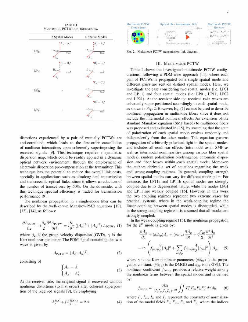
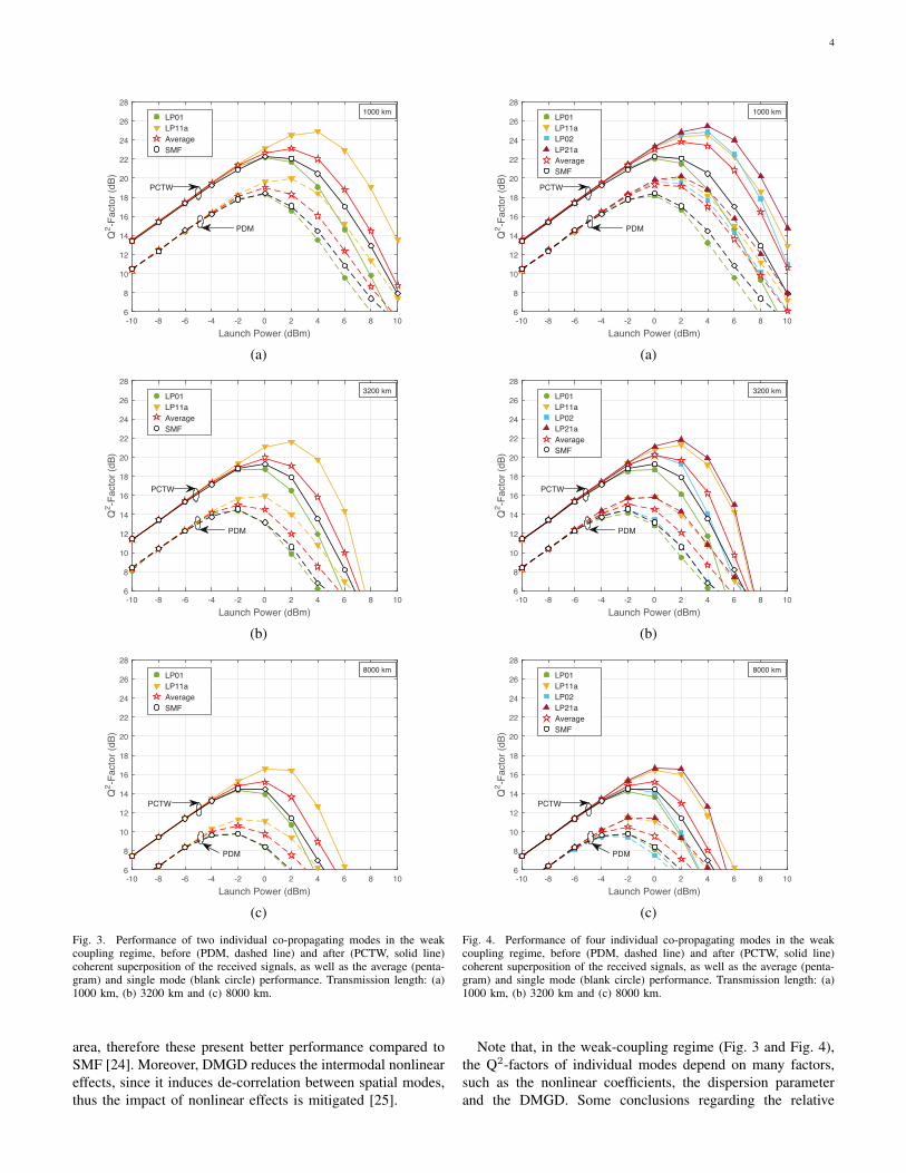
Fig. 3. Performance of two individual co-propagating modes in the weakcoupling regime, before (PDM, dashed line) and after (PCTW, solid line)coherent superposition of the received signals, as well as the average (penta-gram) and single mode (blank circle) performance. Transmission length: (a)1000 km, (b) 3200 km and (c) 8000 km.
area, therefore these present better performance compared toSMF [24]. Moreover, DMGD reduces the intermodal nonlineareffects, since it induces de-correlation between spatial modes,thus the impact of nonlinear effects is mitigated [25].
Launch Power (dBm)
-10 -8 -6 -4 -2 0 2 4 6 8 10
Q2-F
acto
r (d
B)
6
8
10
12
14
16
18
20
22
24
26
28
LP01
LP11a
LP02
LP21a
Average
SMF
1000 km
PCTW
PDM
(a)
Launch Power (dBm)
-10 -8 -6 -4 -2 0 2 4 6 8 10
Q2-F
acto
r (d
B)
6
8
10
12
14
16
18
20
22
24
26
28
LP01
LP11a
LP02
LP21a
Average
SMF
3200 km
PCTW
PDM
(b)
Launch Power (dBm)
-10 -8 -6 -4 -2 0 2 4 6 8 10
Q2-F
acto
r (d
B)
6
8
10
12
14
16
18
20
22
24
26
28
LP01
LP11a
LP02
LP21a
Average
SMF
8000 km
PCTW
PDM
(c)
Fig. 4. Performance of four individual co-propagating modes in the weakcoupling regime, before (PDM, dashed line) and after (PCTW, solid line)coherent superposition of the received signals, as well as the average (penta-gram) and single mode (blank circle) performance. Transmission length: (a)1000 km, (b) 3200 km and (c) 8000 km.
Note that, in the weak-coupling regime (Fig. 3 and Fig. 4),the Q2-factors of individual modes depend on many factors,such as the nonlinear coefficients, the dispersion parameterand the DMGD. Some conclusions regarding the relative
5
Launch Power (dBm)
-10 -8 -6 -4 -2 0 2 4 6 8 10
Q2-F
acto
r (d
B)
6
8
10
12
14
16
18
20
22
24
26
28
LP01
LP11a
Average
SMF
1000 km
PCTW
PDM
(a)
Launch Power (dBm)
-10 -8 -6 -4 -2 0 2 4 6 8 10
Q2-F
acto
r (d
B)
6
8
10
12
14
16
18
20
22
24
26
28
LP01
LP11a
Average
SMF
3200 km
PCTW
PDM
(b)
Launch Power (dBm)
-10 -8 -6 -4 -2 0 2 4 6 8 10
Q2-F
acto
r (d
B)
6
8
10
12
14
16
18
20
22
24
26
28
LP01
LP11a
Average
SMF
8000 km
PCTW
PDM
(c)
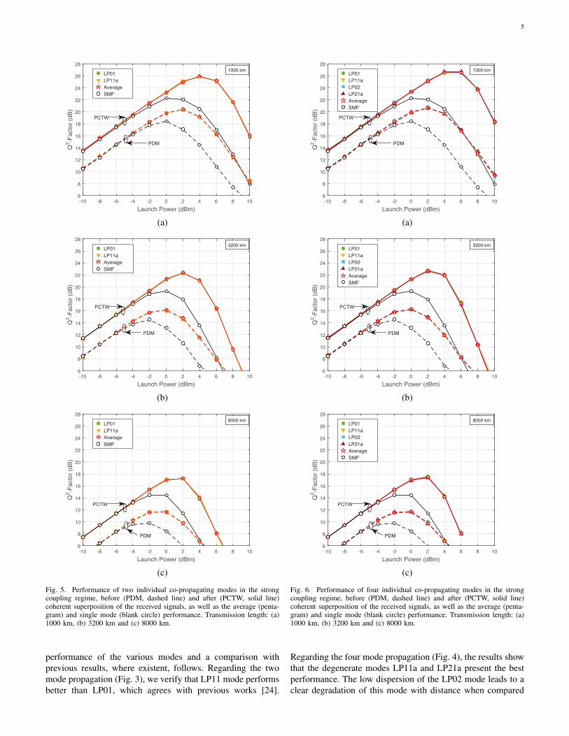
Fig. 5. Performance of two individual co-propagating modes in the strongcoupling regime, before (PDM, dashed line) and after (PCTW, solid line)coherent superposition of the received signals, as well as the average (penta-gram) and single mode (blank circle) performance. Transmission length: (a)1000 km, (b) 3200 km and (c) 8000 km.
performance of the various modes and a comparison withprevious results, where existent, follows. Regarding the twomode propagation (Fig. 3), we verify that LP11 mode performsbetter than LP01, which agrees with previous works [24].
Launch Power (dBm)
-10 -8 -6 -4 -2 0 2 4 6 8 10
Q2-F
acto
r (d
B)
6
8
10
12
14
16
18
20
22
24
26
28
LP01
LP11a
LP02
LP21a
Average
SMF
1000 km
PCTW
PDM
(a)
Launch Power (dBm)
-10 -8 -6 -4 -2 0 2 4 6 8 10
Q2-F
acto
r (d
B)
6
8
10
12
14
16
18
20
22
24
26
28
LP01
LP11a
LP02
LP21a
Average
SMF
3200 km
PCTW
PDM
(b)
Launch Power (dBm)
-10 -8 -6 -4 -2 0 2 4 6 8 10
Q2-F
acto
r (d
B)
6
8
10
12
14
16
18
20
22
24
26
28
LP01
LP11a
LP02
LP21a
Average
SMF
8000 km
PCTW
PDM
(c)
Fig. 6. Performance of four individual co-propagating modes in the strongcoupling regime, before (PDM, dashed line) and after (PCTW, solid line)coherent superposition of the received signals, as well as the average (penta-gram) and single mode (blank circle) performance. Transmission length: (a)1000 km, (b) 3200 km and (c) 8000 km.
Regarding the four mode propagation (Fig. 4), the results showthat the degenerate modes LP11a and LP21a present the bestperformance. The low dispersion of the LP02 mode leads to aclear degradation of this mode with distance when compared
6
AxRX Ay
RX
1000 km
3200 km
8000 km
AxRX + (Ay
RX)*
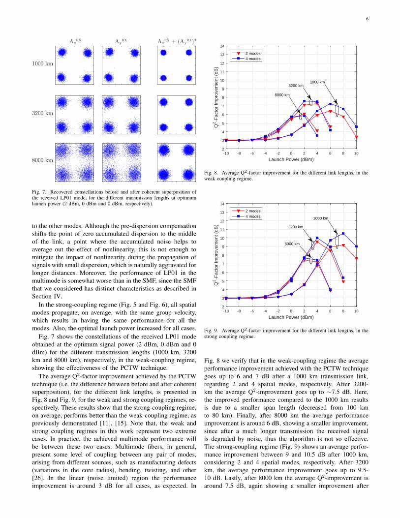
Fig. 7. Recovered constellations before and after coherent superposition ofthe received LP01 mode, for the different transmission lengths at optimumlaunch power (2 dBm, 0 dBm and 0 dBm, respectively).
to the other modes. Although the pre-dispersion compensationshifts the point of zero accumulated dispersion to the middleof the link, a point where the accumulated noise helps toaverage out the effect of nonlinearity, this is not enough tomitigate the impact of nonlinearity during the propagation ofsignals with small dispersion, which is naturally aggravated forlonger distances. Moreover, the performance of LP01 in themultimode is somewhat worse than in the SMF, since the SMFthat we considered has distinct characteristics as described inSection IV.
In the strong-coupling regime (Fig. 5 and Fig. 6), all spatialmodes propagate, on average, with the same group velocity,which results in having the same performance for all themodes. Also, the optimal launch power increased for all cases.
Fig. 7 shows the constellations of the received LP01 modeobtained at the optimum signal power (2 dBm, 0 dBm and 0dBm) for the different transmission lengths (1000 km, 3200km and 8000 km), respectively, in the weak-coupling regime,showing the effectiveness of the PCTW technique.
The average Q2-factor improvement achieved by the PCTWtechnique (i.e. the difference between before and after coherentsuperposition), for the different link lengths, is presented inFig. 8 and Fig. 9, for the weak and strong coupling regimes, re-spectively. These results show that the strong-coupling regime,on average, performs better than the weak-coupling regime, aspreviously demonstrated [11], [15]. Note that, the weak andstrong coupling regimes in this work represent two extremecases. In practice, the achieved multimode performance willbe between these two cases. Multimode fibers, in general,present some level of coupling between any pair of modes,arising from different sources, such as manufacturing defects(variations in the core radius), bending, twisting, and other[26]. In the linear (noise limited) region the performanceimprovement is around 3 dB for all cases, as expected. In
Launch Power (dBm)-10 -8 -6 -4 -2 0 2 4 6 8 10
Q2-F
acto
r Im
prov
emen
t (dB
)
2
3
4
5
6
7
8
9
10
11
12
13
14
2 modes4 modes
3200 km1000 km
8000 km
Fig. 8. Average Q2-factor improvement for the different link lengths, in theweak coupling regime.
Launch Power (dBm)-10 -8 -6 -4 -2 0 2 4 6 8 10
Q2-F
acto
r Im
prov
emen
t (dB
)
2
3
4
5
6
7
8
9
10
11
12
13
14
2 modes4 modes 1000 km
8000 km
3200 km
Fig. 9. Average Q2-factor improvement for the different link lengths, in thestrong coupling regime.
Fig. 8 we verify that in the weak-coupling regime the averageperformance improvement achieved with the PCTW techniquegoes up to 6 and 7 dB after a 1000 km transmission link,regarding 2 and 4 spatial modes, respectively. After 3200-km the average Q2-improvement goes up to ∼7.5 dB. Here,the improved performance compared to the 1000 km resultsis due to a smaller span length (decreased from 100 kmto 80 km). Finally, after 8000 km the average performanceimprovement is around 6 dB, showing a smaller improvement,since after a much longer transmission the received signalis degraded by noise, thus the algorithm is not so effective.The strong-coupling regime (Fig. 9) shows an average perfor-mance improvement between 9 and 10.5 dB after 1000 km,considering 2 and 4 spatial modes, respectively. After 3200km, the average performance improvement goes up to 9.5-10 dB. Lastly, after 8000 km the average Q2-improvement isaround 7.5 dB, again showing a smaller improvement after
7
a much longer transmission length. On average, four co-propagating modes perform better than two modes after a1000 km transmission, whereas for longer transmission lengthsthat difference vanishes, since that for longer distances thereceived signal is degraded by noise and the algorithm is notso effective.
VI. CONCLUSION
The performance of SDM-PCTW has been assessed nu-merically for different co-propagating modes and transmis-sion lengths. Our numerical simulation results show that co-propagating four spatial modes provides better performancethan two spatial modes after a 1000 km fiber transmission,whereas for longer distances that difference is much smaller.PCTW further improves SDM performance by 7 dB in theweak coupling regime and 10 dB in the strong couplingregime, after a 1000 km transmission link. Moreover, formuch longer transmission links (8000 km), the benefit of thistechnique is still significant, showing a Q-improvement around6-7 dB.
REFERENCES
[1] R.-J. Essiambre and A. Mecozzi, “Capacity limits in single mode fiberand scaling for spatial multiplexing,” in Optical Fiber CommunicationConference and Exposition and National Fiber Optic Engineers Confer-ence (OFC/NFOEC), Optical Society of America, 2012, OW3D.1.
[2] P. J. Winzer, “Challenges and evolution of optical transport networks,” inEuropean Conference on Optical Communication (ECOC), pp. 19–23,2010, We.8.D.1.
[3] P. J. Winzer, “Energy-efficient optical transport capacity scaling throughspatial multiplexing,” Photonics Technology Letters, IEEE, vol. 23,no. 13, pp. 851–853, 2011.
[4] P. J. Winzer and G. J. Foschini, “MIMO capacities and outage probabil-ities in spatially multiplexed optical transport systems,” Optics Express,vol. 19, no. 17, pp. 16680–16696, 2011.
[5] D. J. Richardson, J. M. Fini, and L. E. Nelson, “Space-division multi-plexing in optical fibres,” Nature Photonics, vol. 7, no. 5, pp. 354–362,2013.
[6] L. M. Pessoa, H. M. Salgado, and I. Darwazeh, “Assessment of disper-sion map impact on the digital back propagation of long-haul fibre-opticlinks,” Optical and Quantum Electronics, vol. 45, no. 3, pp. 257–269,2013.
[7] X. Chen, X. Liu, S. Chandrasekhar, B. Zhu, and R. W. Tkach, “Experi-mental demonstration of fiber nonlinearity mitigation using digital phaseconjugation,” in Optical Fiber Communication Conference and Exposi-tion and National Fiber Optic Engineers Conference (OFC/NFOEC),pp. 1–3, 2012, OTh3C.1.
[8] D. Rafique and A. Ellis, “Scaling the advantages of intra-channelnonlinearity compensation in future flexible optical networks,” in Euro-pean Conference on Optical Communication (ECOC), p. P4.18, OpticalSociety of America, 2012.
[9] X. Liu, A. R. Chraplyvy, P. J. Winzer, R. W. Tkach, and S. Chan-drasekhar, “Phase-conjugated twin waves for communication beyond theKerr nonlinearity limit,” Nature Photonics, vol. 7, no. 7, pp. 560–568,2013.
[10] X. Liu, S. Chandrasekhar, P. J. Winzer, R. W. Tkach, and A. R.Chraplyvy, “Fiber-nonlinearity-tolerant superchannel transmission vianonlinear noise squeezing and generalized phase-conjugated twinwaves,” Journal of Lightwave Technology, vol. 32, no. 4, pp. 766–775,2014.
[11] J. S. Tavares, L. M. Pessoa, and H. M. Salgado, “Phase conjugatedtwin waves based transmission in few modes fibers,” in InternationalConference on Transparent Optical Networks (ICTON), pp. 1–4, 2015,We.D1.3.
[12] D. Marcuse, C. R. Menyuk, and P. K. A. Wai, “Application of theManakov-PMD equation to studies of signal propagation in optical fiberswith randomly varying birefringence,” Journal of Lightwave Technology,vol. 15, no. 9, pp. 1735–1746, 1997.
[13] P. K. A. Wai and C. R. Menyak, “Polarization mode dispersion,decorrelation, and diffusion in optical fibers with randomly varyingbirefringence,” Journal of Lightwave Technology, vol. 14, no. 2, pp. 148–157, 1996.
[14] P. K. A. Wai, C. R. Menyuk, and H. H. Chen, “Stability of solitons inrandomly varying birefringent fibers,” Optics Letters, vol. 16, no. 16,pp. 1231–1233, 1991.
[15] S. Mumtaz, R. Essiambre, and G. P. Agrawal, “Nonlinear propagationin multimode and multicore fibers: Generalization of the Manakovequations,” Journal of Lightwave Technology, vol. 31, no. 3, pp. 398–406, 2013.
[16] R. Ryf, S. Randel, A. H. Gnauck, C. Bolle, A. Sierra, S. Mumtaz,M. Esmaeelpour, E. C. Burrows, R. Essiambre, P. J. Winzer, D. W.Peckham, A. H. Mccurdy, and R. Lingle, “Mode-division multiplexingover 96 km of few-mode fiber using coherent 6x6 MIMO processing,”Journal of Lightwave Technology, vol. 30, no. 4, pp. 521–531, 2012.
[17] D. Gloge, “Weakly guiding fibers,” Applied Optics, vol. 10, no. 10,pp. 2252–2258, 1971.
[18] D. Gloge, “Dispersion in weakly guiding fibers,” Applied Optics, vol. 10,no. 11, pp. 2442–2445, 1971.
[19] M. J. Adams, An introduction to optical waveguides. UMI Books onDemand, 1981.
[20] A. Ghatak and K. Thyagarajan, Introduction to fiber optics. Cambridgeuniversity press, 1998.
[21] K. Iizuka, Elements of Photonics, vol. 2. John Wiley & Sons, 2002.[22] G. P. Agrawal, Nonlinear fiber optics. San Diego, CA: Academic,
4th ed., 2007.[23] A. J. Lowery, L. B. Du, and J. Armstrong, “Performance of optical
OFDM in ultralong-haul WDM lightwave systems,” Journal of Light-wave Technology, vol. 25, no. 1, pp. 131–138, 2007.
[24] F. Ferreira, S. Jansen, P. Monteiro, and H. Silva, “Nonlinear semi-analytical model for simulation of few-mode fiber transmission,” Pho-tonics Technology Letters, IEEE, vol. 24, no. 4, pp. 240–242, 2012.
[25] C. Koebele, M. Salsi, G. Charlet, and S. Bigo, “Nonlinear effects inmode-division-multiplexed transmission over few-mode optical fiber,”Photonics Technology Letters, IEEE, vol. 23, no. 18, pp. 1316–1318,2011.
[26] K.-P. Ho and J. M. Kahn, “Linear propagation effects in mode-divisionmultiplexing systems,” Journal of Lightwave Technology, vol. 32, no. 4,pp. 614–628, 2014.