Embed Size (px)
Citation preview

J. Plasma Physics (1990), vol. 44, part 2, pp. 337-360 337
Printed in Great Britain
Nonlinear magnetic reconnection models withseparatrix jets
By E. R. PRIESTf AND L. C. LEE
Geophysical Institute, University of Alaska, Fairbanks, Alaska 99775-0800, U.S.A.
(Received 26 February 1990 and in revised form 29 June 1990)
A new theory for fast steady-state magnetic reconnection is proposed thatincludes many features of recent numerical experiments. The inflow regiondiffers from that in the classical model of Petschek (1964) and the unified linearsolutions of Priest & Forbes (1986) in possessing highly curved magnetic fieldlines rather than ones that are almost straight. A separatrix jet of plasma isejected from the central diffusion region along the magnetic separatrix. Twotypes of outflow are studied, the simplest possessing an outflow magnetic fieldthat is potential. The other contains weak standing shock waves attached to theends of the diffusion region and either slowing down the flow (fast-mode shock)after it crosses the separatrix jet or speeding it up (slow-mode), depending onthe downstream boundary conditions. A spike of reversed current slows downthe plasma that emerges rapidly from the diffusion region into the more slowlymoving downstream region, and diverts most of it along the separatrix jets. Inthe simplest case the outflow possesses no vorticity over most of the downstreamregion. The models demonstrate that both upstream and downstream boundaryconditions are important in determining which regime of reconnection isproduced from a wide variety of possibilities.
1. IntroductionIn the overall picture of a steadily reconnecting configuration (figure 1),
oppositely directed magnetic fields are carried in by a flow towards a centraldiffusion region or current sheet OY of length L. They are broken andreconnected at an X-type magnetic neutral point within the diffusion regionand are then expelled outwards. The external field strength and inflow speed ata point A at a distance Le, say, from O are denoted by Be and ve, while thecorresponding inflow values just outside the diffusion region are Bi and v(, andthe outflow values at a point C a distance Le from O are Bo and v0. Adimensionless form of the flow speed is the Alfven Mach number
M = ~, (1.1)VA
where vA = B/(/ip)* is the Alfven speed. A shock wave YH (normally of slow-mode type) stands in the flow and turns the inflowing plasma to the right, atthe same time decreasing the magnetic field strength. In the incompressible case
t Permanent address: Mathematical Sciences Department, The University, St Andrews,Fife KY16 9SS, Scotland.

338 E. R. Priest and L. C. Lee
Bo, vo
FIGURE 1. One quadrant of a reconnecting configuration, indicating schematically themagnetic field lines (arrowed), the central current sheet OY, the separatrix YS and the shockwave YH.
that is being analysed in this paper, YH becomes an Alfve'nic discontinuity ofslow- or fast-mode type, but we shall still loosely refer to it as a shock.
Apart from understanding the detailed structure of the plasma flow andmagnetic field, the main aims of reconnection theory have been to determinehow the length L of the central current sheet varies with the external AlfvenMach number Me and to find whether there is a maximum allowable(dimensionless) reconnection rate (Me) less than unity.
The two key assumptions of the classical Petschek (1964) analysis are that(i) the inflow magnetic field is current-free (or potential), and(ii) the inflow magnetic field lines are almost straight.
In other words, Petschek (1964) considered a linear potential perturbation to auniform magnetic field (-Bgx) in the inflow region. The resulting value of the fieldat the inflow to the sheet is
Bt-B. (1.2)
and so, by putting Bt = \Be, he estimated the maximum reconnection rate M*to be
M t = f i ] n7 ' r , r - (1-3)
8 log LJLFor the diffusion region (of width I) to be in a steady state, the inwardsadvection of magnetic flux must balance its outwards diffusion, and so
vt = l (1.4)
Reconnection models 339
If the plasma is expelled from the diffusion region at the inflow Alfven speed vAi,conservation of mass in the incompressible case implies
Lvi = lvAi. (1.5)
Furthermore, in a steady-state two-dimensional configuration with themagnetic field frozen to the plasma, the electric field E is uniform and equal tovxB everywhere, where vx is the plasma flow speed perpendicular to themagnetic field. Thus, evaluating this at both A and the inflow to the currentsheet gives
vtBt = v,Bt. (1.6)Finally, elimination of I and vt between (1.4)-(1.6) gives
(1.7)
so that the maximum reconnection rate (1.3) becomes
typically 001-01.Subsequently, Sonnerup (1970) proposed a model with an extra discontinuity
in the inflow region ahead of the slow shock for which the maximumreconnection rate is of order unity. Vasyliunas (1975) pointed out thatPetschek's inflow region has the character of a weak fast-mode expansion, whileSonnerup's extra discontinuity is a slow-mode expansion generated at someexternal point. Also, Parker (1973) and Sonnerup & Priest (1975) discovered astagnation-point flow solution with straight field lines, while Sonnerup & Wang(1987) studied the structure of the downstream region in detail, treating it asa narrow boundary layer.
More recently, Priest & Forbes (1986) presented a unified theory for linearreconnection: linear in the sense that the inflow magnetic field is a linearperturbation to a uniform state (assumption (ii) above). They did this bygeneralizing assumption (i) and allowing the inflow configuration to possesssignificant pressure gradients. The result is a continuous sequence ofreconnection regimes, of which Petschek's solution and a Sonnerup-like solutionwith a diffuse slow-mode expansion are particular members. It is the inflowboundary conditions along the boudnary AD that determine which regime ofreconnection is produced. The theory was developed further by Jardine &Priest (1988a-c), who extended it to include compressibility and to allow aweakly nonlinear inflow by considering the second-order terms.
Numerical experiments on steady magnetic reconnection (Biskamp 1982,1984, 1986; Forbes & Priest 1982, 1983, 1984; Lee 1986; Lee & Fu 1986; Fu &Lee 1986; Scholer 1989) have revealed four new features that are not present inthe classical models:
(a) the inflow is usually not a weak fast-mode expansion with slightlyconverging field lines and a weakening field strength;
(b) the inflow magnetic field may be highly nonlinear with a strong curvature;(c) there may be strong jets of plasma along the separatrices;(d) spikes of strong reversed current may be present near the ends of the
diffusion region.It was feature (a) that stimulated Priest and Forbes to develop their unified

340 E. R. Priest and L. C. Lee
theory for linear reconnection, in which the inflow may have the character ofa slow-mode compression, fast-mode expansion or slow-mode expansion,depending on whether the inflow is converging or diverging. Forbes & Priest(1987) have shown in detail the way in which many features of the inflow regionin numerical experiments may be understood in terms of this theory. Theelements of a theory for the separatrix jets has been presented by Habbal &Tuan (1979) and Soward & Priest (1986), while Jardine & Priest (1988d) havegiven a physical argument for the existence of the reversed currents.
It is the aim of the present paper to set up a theory which incorporatesfeatures (6), (c) and (d) for the first time; §2 gives some physical considerationsto suggest why the inflow magnetic field may be highly curved and why theshocks, separatrix jets and reversed currents are present; §3 gives a basic modelwithout shocks; §4 incorporates the shocks and analyses the resultingnonpotential downstream region. The main conclusions are summarized in thefinal section.
2. Physical considerations
Before embarking on the mathematical analysis, let us first briefly considerthe following physical questions. Why is the inflow magnetic field often highlycurved? Why are the shock waves present? What causes the separatrix jet?Why do the reversed current regions exist near the ends of the diffusion region ?Forbes & Priest (1987) have stressed that the number of independent boundaryconditions that may be imposed in a magnetohydrodynamic situation is equalto the number of characteristics that are propagating information into theregion, and so it depends on the magnitude of the inflow or outflow speed. Inparticular, for two-dimensional coplanar incompressible ideal MHD (the casestudied here), when there is an inflow slower than the normal Alfven speed,three boundary conditions may be imposed, such as the normal flow speed vn,the tangential flow speed vt and the pressure p; for faster inflows four conditionsmay be specified.
Consider, for example, the inflow boundary AD in figure 1, and suppose thatwe prescribe
vx — 0, vy = ve (a constant), p = pe (a constant) (2.1)
along AD. Then the electric field equation
E + v x B = 0 (2.2)
Ewith E uniform implies that B
>
is constant, while V.B = 0 (2.3)
implies that By = By(x).
Furthermore, provided dvjdy = dBJdy = 0, the x component of the equationof motion
( V x B ) x B (2.4)
reduces to 0 = ~ ( » + M,ox \ 2/i j

Reconnection models 341
so that By has a constant value, which must be zero in order to make By vanishon the axis of symmetry (x = 0).
In other words, imposing the boundary conditions (2.1) implies that themagnetic field is uniform on the boundary and parallel to it. If instead oneimposes values of vx, vy and p only slightly different from those in (2.1) then amagnetic field with a slight curvature may be produced, as studied in themodels of Petschek (1986) and Priest & Forbes (1986). Imposing boundaryconditions greatly different from (2.1) would in general produce highly curvedmagnetic field lines. In other words, the feature (6) mentioned in the previoussection is a direct consequence of the form of the imposed boundary conditions.
Soward & Priest (1977) have described in detail the role of characteristics inthe reconnection problem. The curl of (2.2) gives
(v.V)B-(B.V)v = 0, (2.5)
and so for an incompressible plasma (2.4) and (2.5) may be combined to give
i ( g) (2.6)
(2.7)
Bwhere v+ = v + vyj> v - = v""v^> VA
In other words, when the total pressure p+B2/2/i is uniform, the quantity v_ isconstant along the characteristics C_ (the streamlines for the quantity v_) andv_ is constant along the characteristics C+ (the streamlines for v+). When thetotal pressure is non-uniform, its gradient acts as a continuous distribution ofsources for the wave equations everywhere in the flow.
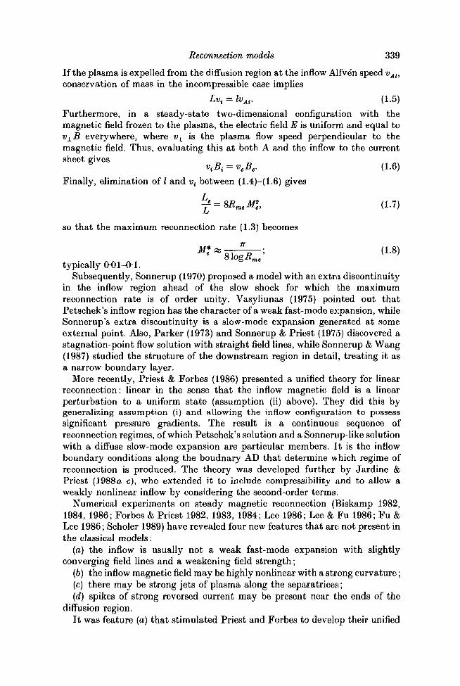
The C+ characteristics are shown schematically in figure 2 (a), where it can beseen how they propagate information from both sides in towards the particularcharacteristic YS which comes from the end (Y) of the central current sheet. Itis because the information contained in v_ cannot propagate upstream that anAlfvenic discontinuity may in general exist along YS. In the compressible casethis becomes a slow-mode shock in Petschek's model, where the shock existsphysically because the inflow is super-slow-magnetosonic, since the slowmagnetosonic speed is zero for propagation across the field. We shall find inpractice (see e.g. figure 46) that the streamlines are highly distorted from thoseindicated schematically in figure 2(a), coming in to the separatrix and leavingit at small angles. In the limit when the half-length OY of the central diffusionregion vanishes, there is no flow along the separatrix itself and a double jet ofplasma exists with a strong inflow towards 0 upstream of the separatrixtogether with an outflow downstream. When OY is non-zero, the separatrix jetconsists of a similar double jet together with an extra outflow along theseparatrix, which essentially represents the outflow of the plasma that flowsinto OY and is then diverted along the separatrix. Since there is a net mass fluxalong the separatrix, we shall use the term 'separatrix jet' even though it hasa complex structure.
In numerical experiments with very high resolution, notably the excellentones of Biskamp (1986) and Lee & Fu (1986), much of the plasma that enters
342 E. R. Priest and L. C. Lee
Fast-mode
FIGURE 2. (a) Schematic representation of the magnetic field lines ( —>— ), streamlines( —•— ) and C+ characteristics ( — >-—). (b) Notation at a point P on the shock that is inclinedat an angle 6 to the x axis: > , downstream field line (B2) for a fast-mode shock;•••«•— , downstream flow streamline (v2) for a fast-mode shock; •••>•••• , B2 for a slow-modeshock; ••••, v, for a slow-mode shock.
the diffusion region is not observed to flow outwards along the direction of thediffusion region, as in Petschek's model. Instead it escapes in strong jets alongthe separatrices, the magnetic field lines that intersect at the X-type neutralpoint in the core of the diffusion region (figure 3). With hindsight, this is notsurprising since, if there is a partial magnetic blockage at the ends of the sheet(associated with a reversed current), outflow along the separatrix will beunimpeded magnetically since there is no magnetic force along it.
When the outflow is sub-Alfvenic with respect to the transverse magneticfield, at the outflow boundary DH in figure 1, two conditions may be imposed,such as vn and vt; but when it is super-Alfvenic, one boundary condition maystill be prescribed, such as vn (Forbes & Priest 1987). Thus, in the nonlinearregime, there is a whole new continuum of possible solutions depending on what

Reconnection models 343
FIGURE 3. (a) Overall mass flux into and out of the diffusion region. (6) Streamlines, showingthe central ones, which pass out of the ends, and the outer ones (shaded region), which aredeflected along the jet and then by the shock (dashed).
is imposed on the outflow boundary. In the Petschek solution and the linearunified solutions of Priest and Forbes, there is no such freedom since the outflowspeed is the upstream Alfven speed. However, in the weakly nonlinear solutions(Jardine & Priest 19886) the freedom to impose the outflow speed at next orderis present.
Reversed currents near the ends of the diffusion region have been observedin many numerical experiments (Podgorny & Syrovatsky 1981; Forbes & Priest1982; Forbes 1986; Biskamp 1986; Lee & Fu 1986). In an extreme case wherethe outflow speed is zero, so that there is a magnetic obstacle downstream,Forbes (1986) performed a detailed analysis of the numerical data and foundthat the reversed current consists of a fast-mode shock, which slows down theplasma flowing out of the diffusion region, followed by a deflection current,which deflects it sideways.
The reversed currents seem to be produced because of a mismatch (Jardine& Priest 1988a!) between the prescribed (often slow) speed at the outflowboundary and the Alfven speed with which the plasma is being squeezed out ofthe diffusion region. The Lorentz force associated with the reversed currentslows down the plasma and may deflect it along the separatrices. Thus onewould expect the combination of a long diffusion region (into which a lot ofmass is flowing) and a slow imposed outflow speed to produce large reversedcurrents and strong separatrix jets. The magnitudes of the reversed currentsand separatrix-jet mass flux may be expected to increase as the diffusion-regionlength increases and the outflow speed is reduced.
3. Basic modelOur aim is to construct a reconnection model with highly curved (i.e.
nonlinear) inflow magnetic fields, separatrix jets and reversed currents. Inparticular, it is of interest to determine the relation L = L(Me) between thediffusion-region half-length L and the external inflow Alfven Mach number Me.We need to calculate in turn the magnetic field upstream of the shock, the
344 E. R. Priest and L. C. Lee
upstream flow, the diffusion region parameters, the shock relations, and thedownstream flow and field. In the process, the values of the external inflow.speed ve, field Be at a distance Le and the outflow speed v0 will be prescribed.
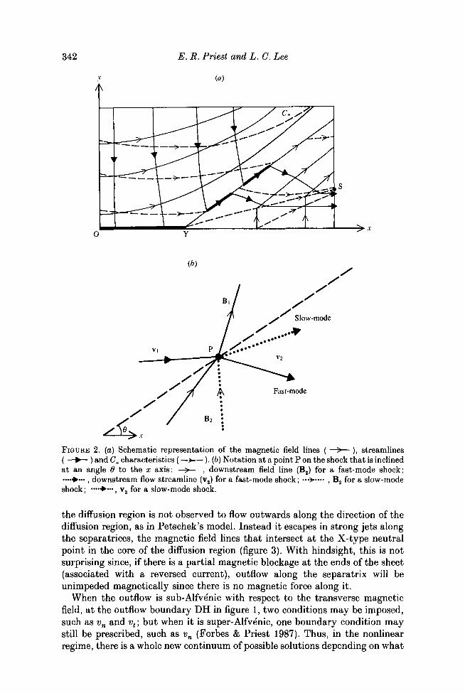
3.1. Upstream magnetic and velocity fieldsThe basic equations to be solved for a steady-state two-dimensional flow(vx(x,y),vy(x,y)), magnetic field (Bx(x,y),By(x,y)) and pressure p(x,y) are theelectric field equation (2.2) with E = Ei. uniform, the magnetic field constraint(2.3), the equation of motion (2.4) with density p uniform, and the mass- •continuity equation
V.v = 0. (3.1)For simplicity, we shall assume that the inflow is highly sub-Alfvenic and the
plasma beta much less than unity, so that (2.4) reduces to
V x B = 0, (3.2)
which, together with (2.3), implies that the magnetic field is potentialeverywhere except at the current sheet of half-length L. The solution for theupstream magnetic field that we shall adopt outside the current sheet is
j (3.3)
where Z — x + iy is a complex variable and there is a cut in the complex planefrom Z = L to Z = — L. Bt is the value of Bx at the origin just above the currentsheet, i.e. at the inflow to the diffusion region. Equating real and imaginaryparts of (3.3) after squaring yields expressions for Bx, By and B:
B\ = ^{-{x2-L2-y*) + [{x2-L2-y2)2 + ±x2y2t, (3.4)
^ % (3-5)
B2 = | § [y* + 2y2(x2+Li) + (x2 -L2)a] i (3.6)
Evaluating (3.3) at the point A(0,Le) in figure 1 gives an expression for Bt interms of the external field Be:
Furthermore, the flux function A such that
dA dAB* = -dy-' By = -c%
can be found from (3.4) and (3.5) to be
K*+°>'+te+^j (38)
where
\ \ lX]*, X = x2-y2-L\ Y = 2xy.

Reconnection models 345
Having obtained the magnetic field from (3.4) and (3.5) with Bi given by(3.7), we must next calculate the velocity from (2.2) and (3.1) with
E = -veBe. (3.9)
First of all, we can evalute (2.2) at the points 0 and C (where the velocity andmagnetic field are perpendicular) to give v( in terms of Bi and v0 in terms of Bo
as
vo = V-^. (3.11)
Indeed, in general (2.2) implies that the flow speed perpendicular to themagnetic field is
with B given by (3.6), and then (3.1) determines the flow speed parallel to themagnetic field.
A useful way to determine v is to write it in terms of a stream function T suchthat
x dy' y dx'
so as to satisfy (3.1) automatically. Then (2.2) reduces to
with solution Y = veBe —, (3.14)
where the integration is along a magnetic field line. For field lines above theseparatrix YS in figure 1, one integrates from a point on the y axis where *F = 0since the y axis is a streamline (*F = 0). For field lines below the separatrix,one integrates from a point on the lower boundary (YC) where *F = 0. Theseparatrix itself becomes a vortex-current sheet, whose structure Soward &Priest (1986) have discussed. Across the sheet, the flow velocity abruptlychanges direction, but in practice, just the like the central diffusion region, sucha sheet is broadened to a finite thickness by viscosity and magnetic diffusion.
3.2. The diffusion region
On y = 0 just above the current sheet the magnetic field strength is
Bx = —l-(L2—x2)*, (3.15)
and so the inflow speed into the sheet is
Vy = v J $ J L = z i L2 i , (3-16)
where v{ = veBe/Bi. Thus the mass flux into the half-sheet from above is
pvydx = \npLvi. (3.17)fJo

346
L = 005 L,.
E. R. Priest and, L. C. Lee
(a)
L = 0-2 Le
xlLc 1 0 x/Z.,,
FIGURE 4. For caption see facing page.
In order of magnitude, if a fraction / of the incoming mass flows out of theend of the sheet at the Alfven speed vM and a fraction 1 —/ goes out along theseparatrix then mass continuity implies
= vMl, (3.18)
(3.19)
(3.20)
where vt = veBe/Bf and vAi = vAeBJBe. Also, steady diffusion implies
«« = - .
and so elimination of I between (3.18) and (3.19) gives
2<£- B*t
in terms of the external magnetic Reynolds number Rme and Alfven Machnumber Me, where BJBe is given by (3.7).
If L/Le is known then (3.20) determines the fraction/, whereas i f / is foundfrom some as yet unknown properties of the current sheet and the reversed

L = 005 £.,
Reconnection models
(b)
L = 0-2 Le
347
L = 0-4 Le L = 0-6 Le
FIGURE 4. (a) Magnetic field lines and (b) streamlines for shockless reconnection. Four valuesof the current sheet half-length L are shown (0'05Le, 0-2Le, 0-4Xie, 0-6Le), with the sameexternal field Be and flow ve.
current region then (3.20) determines L/Le. We shall use (3.20) in the followingsections, but it is also of interest to note that the variation of the width of thesheet is given by _V _V (L2-x2)*
l{x) = = - ,vy vt L
and so the sheet narrows towards its end and l(x) decreases as the inflow speedincreases. At the same time, the variation in the flow along the sheet may befound from mass continuity,
vxl(x) = Vydx = V( Lsin 1 —,
so that
Thus the flow speed increases with distance. In practice, there will be a cut-offbefore x reaches L, and therefore the sheet will possess a minimum width anda maximum outflow speed. Such a narrowing of the sheet to a neck may be seenin some of the numerical experiments.

348 E. R. Priest and L. C. Lee
3.3. Shockless reconnectionConsider first for simplicity the case when there is no shock wave present or itis very weak, so that the magnetic field is given by (3.3) everywhere outside thecurrent sheet. The stream function follows from (3.14), where the integral forstreamlines below the separatrix is performed by integrating from a point onYC where *F = 0, so that one has here given up the ability to prescribe thestream function on SC. Plots of magnetic field lines and streamlines are shownin figure 4 for four particular values of L. The effect of increasing Be is simplyto introduce more field lines without changing the direction of the magneticfield. Also, increasing ve does not change the shapes of the streamlines, butsimply scales up the magnitude of the flow everywhere. In order to be able tofollow the streamlines through the diffusion region and along the separatrix, thestream function has been smoothed over small regions of width 8A = 001BeLe
at the diffusion region and separatrix, where (3.14) with (3.3) leads todiscontinuities.
The outflow field strength Bo is given by evaluating (3.5) at (Le, 0) with Bt
given by (3.7), and soB
The outflow speed v0 follows from (3.11) as
Also, by substituting forB(/Be from (3.7), the diffusion region relation becomes
If one insists that none of the inflow to the diffusion region flows along thejet and so puts / = 1 then (3.23) determines L/Le to be a monotonicallyincreasing function of Me, with the maximum reconnection rate M* being givenby
*?=-Aand so having a Sweet-Parker scaling.
If instead one allows a separatrix jet and imposes the value of v0 then (3.22)determines the sheet half-length L/Le as
(3.24)
Thus, as ve increases from zero (with v0 held constant) up to a maximum valueof v0, so the sheet half-length L decreases from Le to zero (figure 5a). (Forexample, if v0 is held equal to the local Alfven speed vAo = vAeB0/Be thenL?/L\ = (1 —Me)/(i +Me), and L decreases from Le to zero as Me increases from0 to 1.)
At the same time, the fraction / of plasma-diffusion-region plasma that doesnot flow out along the separatrix jet is given from (3.23) and (3.24) by
mev\. irtiv\/vlvAe

Reconnection models 349
I02
v 10
5? '10-'
io-2
0-5
v,/vo
10
10
FIGURE 5. For shockless reconnection with' a constant outflow speed v0, the variation withexternal inflow speed vt of (a) diffusion-region length L; (6) the fraction / of diffusion regionplasma not escaping along the separatrix jet; (c) diffusion-region width; (d) magnetic-energyconversion, where Wt is the external inflow of magnetic energy and Wo the outflow.
as plotted in figure 5(b). Thus, unless ve is extremely small, the presence of thefactor Rme(p 1) means t h a t / ^ 1 and most of the plasma flows out along thejet. For example, for ve « vAe,f « R^e.
The sheet width is given from (3.7), (3.10), (3.19) and (3.22) as
As shown in figure 5(c), it decreases from rj/(2*ve) to zero as ve increases fromzero to v0.
The inflow of magnetic energy through AD in figure 1 is
We = veBe[L'Bx(x,Le)dx,
Jo
where Bx is given by (3.4), B{ by (3.7) and L by (3.24). Also, the outflow ofmagnetic energy through DC is
fJ

350
10
? 0-5
0
0-4-
-
^ ^0 2 ^ ^ = ^
L/Le = 005
1 i
0-6
-
E. R. Priest and L. C. Lee
0
-l
2-0
0-5
xlLe
(c)
10
10
04^
= = :0-2 -
-
i
ULe = 0-6
i
-
0 0 5 ^ ""
0-5
20
0
-20
LILe =
-
-
id)I
0-61
J
I
/0-4
/
0-6 /
\
0-4
-1 /-
305"
0-2
10 0-5
ylL,
10
FIGURE 6. (a, b) Variation with distance along the inflow boundary A of (a) the flow speedvy normal to the magnetic field and (b) the flow speed t̂ parallel to the field, (c, d) Thevariation with distance along the outflow boundary of (c) v± and (d) vf.
where By is given by (3.5). The rate of magnetic-energy conversion as a fractionof the inflow of magnetic energy is therefore (We— Wo)/Wo and is plotted as afunction oive/v0 in figure 5(d). I t declines from a maximum value of about 0 6at ve = 0 to zero when ve = v0. For given values of v0 and Be, the absolute rateof magnetic-energy conversion is proportional to ve(We— Wo) and so increaseswith ve up to a maximum value and then declines to zero as ve approaches v0.
The way in which the flow velocity components vary with distance along theinflow and outflow boundaries is shown in figure 6. Generally, the flow speed v±
perpendicular to the magnetic field decreases with distance from the axes. Itincreases with L on both the inflow and outflow boundaries. The flow v^ alongthe field on the inflow increases in magnitude with distance from the axis anddecreases with L. On the outflow boundary the parallel flow speed increases upto the separatrix jet and increases with L.
4. Reconnection with shocksThe characteristic W+A = constant which comes from the end (Y) of the
current sheet may support an Alfvenic discontinuity (a shock in thecompressible case), since a disturbance generated at Y may propagate out along

Reconnection models 351
0 1x/Le 1 0 xlL,
FIGURE 7. Characteristics *¥ + A = constant for L = 0-2Le, with the inflow Alfven Machnumberitf, = 0-05 (a), 0-2 (b), 0-4 (c) and 05 (d).
it (i.e. YH). The position of the characteristic depends on the magnitude of theflow (figure 7), since a very slow flow produces characteristics that are inclinedonly slightly to the field lines (except the separatrix), and, as the flow speedincreases, so the angle of inclination increases and the spacing between theseparatrix and the shock widens.
For the upstream region ahead of the shock, the magnetic field and flow arestill given by (3.3) and (3.14), but the shock modifies the region downstream ofthe shock. Having found the shock position, we therefore need to apply theshock relations and then determine the downstream flow, bearing in mind thatwe are free to specify one condition at the outflow boundary HC (see §2).
4.1. Shock relations
In our incompressible regime, the condition that W+A ••= constant, orequivalently that the normal flow vn be related to the normal Alfven speed vAn
^ v +v = 0, (4-1)
determines the shape and position of the shock YS at each point P along itslength starting from the end Y of the current sheet. In other words, itdetermines the angle 6 of inclination of the shock at P.
12 PLA 44

352 E. R. Priest and L. C. Lee
L = 005 L,. L = 0-2 Le
x/L,
FIGURE 8. For caption see facing page.
At each point on the shock front, we shall find only four independentconditions relating the five downstream variables Vj, Bx and j)x (figure 26). Suchan indeterminancy is expected, since we are able to prescribe one outflowvariable. The conservation relations are as follows.
Conservation of mass
gives vx2 sin 6 — vy2 cos 0 = vxl sin 6 — vyl cos 6
and determines one of vx2 and vy2 once the other is prescribed.Conservation of magnetic flux
'n\
becomes Bx2 sin 6—By2 cos 6 = Bxlsind—Bylcos6
Conservation of electric field (E = — v x B) may be written as
v R —v R = v R —v Rux2JJy2 vy2±Jx2 "xldJyl vy\±Jx\'>
and so (4.5) and (4.6) together determine Bx2 and By2.
(4.2)
(4.3)
(4.4)
(4.5)
(4.6)
L = 005 L,.
Reconnection models
L = 0-2 Le
353
j 1
1 I 1/
/ / / /
1 / ///I/ /oA
I. —_—
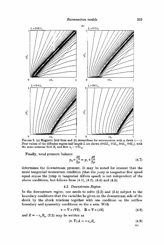
0 xlLe 1 0 xlLe 1FIGURE 8. (a) Magnetic field lines and (6) streamlines for reconnection with a shock ( ).Four values of the diffusion region-half length L are shown (0-05L,, 0-2Le, 0-4Le, 0-6Le), withthe same external field B, and flow v. = 0'2«,,.
Finally, total pressure balanceB\
(4.7)
determines the downstream pressure. It may be noted for interest that theusual tangential momentum condition (that the jump in tangential flow speedequal minus the jump in tangential Alfven speed) is not independent of theabove conditions, but follows from (4.1), (4.2), (4.4) and (4.5).
4.2. Downstream Region
In the downstream region, one needs to solve (2.2) and (2.4) subject to theboundary conditions that the variables be given on the downstream side of theshock by the shock relations together with one condition on the outflowboundary and symmetry conditions on the x axis. With
v = V x CF4), B = V x (Az) (4.8)
and E = —veBe, (2.2) may be written as
(v.V)A=-veBe. (4.9)12-2

354 E. R. Priest and L. C. Lee
Also, the curl of (2.4) becomes
/o(v.V)w = (B.V)j (4.10)
in terms of the vorticity u> = — V2xF and current j = —We shall consider two models for the downstream flow. In the first, we shall
for simplicity assume that the flow is locally super-Alfvenic, so that (4.10)reduces to
(v.V)w = 0. (4.11)This is a good approximation away from the reversed-current spike and theoutflow boundary, where the field is weak and the flow fast. The shocklessmodel of § 3 gives an outflow speed (v0) and outflow field strength Bo of
so that the outflow Alfven Mach number is
L2e+L*
Mn =- Ll-W•"e
Thus, for example, if-Me = 05 then Mo > 2 and so (4-11) is a good approximationeven near the outflow boundary when L/Le > 3~* « 0-6.
One way to solve (4.9) and (4.11) is to assume that the shock switches off they component of the flow velocity so that in the downstream region v = vx(y) xand (o = (o(y). Equation (4.11) is then satisfied identically and (4.9) determinesthe distortion of the magnetic field produced by the shear flow. However, theresulting vorticity has a singularity everywhere along the x axis and so we shallnot adopt this approach.
The simplest solution is to assume w = 0 just downstream of the shock, sothat (4.11) implies that the whole downstream region is vorticity-free and wehave
V2lF = 0. (4.12)The boundary conditions to solve this are as follows. First, along the shock YS,*F — f(s), where/(s) is determined from the shock condition (4.2) to be the sameas the stream function just upstream. Secondly, along the x axis (YC), T = 0,since it is the same streamline that comes in along the y axis. Finally, wemay impose any functional form *F(y) along the outflow boundary that joins*F(0) = 0 at C to the value Y(h) at the point H where the shock reaches theboundary. For simplicity, we shall adopt a linear function, corresponding toa uniform outflow.
The resulting field lines and flow that follow from solving (4.11) and (4.8) areshown in figure 8 for (approximately) the same values of the external field Be
and flow ve, but with different sheet half-lengths L. The shock wave is very weakindeed and is of slow-mode expansive type, increasing the flow speed veryslightly and decreasing the field strength. This is because in the shockless casethe flow is faster on the x-axis, whereas we are imposing a uniform outflow, andso the shock needs to bend the streamlines downward. If we had insteadimposed a much weaker outflow near the x axis then a slow-mode compressiveshock would have been required to bend the streamlines upward. It should benoted that in our incompressible model here the fast-mode wave speed isinfinite, and so standing fast-mode shocks are impossible. Indeed, the

200
Reconnection models
(a)
355
100 -
005 /
™ 1 Jft)
LILe = 0-6
1 /
A
\ —
FIGURE 9. (a) Variation with x of the downstream current density along the z-axis. (b)Relation between L/Lt and vjvo for different values of external inflow speed vt. L is the sheetlength and v0 the outflow speed. The shockless solution is shown dashed.
discontinuities that we have loosely called 'shocks' are really Alfvenicdiscontinuities of slow-mode type, across which there is a change of pressure(unlike an Alfven wave) but no change in density. When compressibility isallowed, the compressible discontinuity becomes a true slow-mode shock, whilethe expansive discontinuity becomes a narrow slow-mode expansion fan.

356 E. R. Priest and L. C. Lee
L = 005 Lf
(a)L = 0-2 Le
xlLe 1 0 xlL, 1
FIGURE 10. For caption see facing page.
An important feature is the reversal in curvature downstream produced bythe fast stream of plasma near the x axis emerging into the much slower streamat the outflow boundary. The variation with x of the resulting strong reversedcurrent along the x axis is shown in figure 9 (a). Also, the variation with vjvo
of L/Le for different values of ve is given in figure 9(fc) in comparison with theshockless solution of figure 5 (a). The outflow speed v0 at C is faster than in theshockless case because of the fast shock and because the uniform outflowboundary condition redistributes the mass flux by speeding up the flow near Cand slowing it down near S. An increase in sheet length increases v0, as in theshockless case.
The above model for the downstream flow is reasonable for much of thedownstream region, and it shows how the region of reversed curvature iscreated. However, it is poor near the outflow boundary when a sub-Alfvenicoutflow is being imposed and it also fails in the reversed-current spike byoverestimating its intensity. The resulting magnetic force will tend to slowdown the outflowing stream more efficiently and so prevent the shear invelocity building up the magnetic gradient so much.

L = 005 Le
Reconnection nodels(h)
L = 0-2 Le
357
FIGURE 10. Reconnection with a shock and with the full downstream solution showing (a)magnetic field lines, (6) streamlines and (c) variation with x of the downstream currentdensity along the x axis.

358 E. R. Priest and L. C. Lee
We have therefore considered a second model by solving the followingincompressible MHD equations
^ , (4.13)
> (4.14)
to obtain the steady-state solution in the outflow region downstream of theshock. The boundary conditions imposed along the outflow boundary (x = 1)are that ^(l,z) is a linear function of z to give a uniform outflow as before,dw/dx = 0, and d2A/dx2 = 0. The boundary conditions along the outflow axis(y = 0) are conditions of symmetry, namely i/r = 0, w = 0, dA/dy = 0. Theboundary conditions imposed along the shock front YH are that iff and A havethe same values as just upstream of the shock, while the vorticity wn+1 along theshock front YH at time step n+ 1 is obtained from the stream function i/rn attime step n: wn+1 = — V2^n. The initial values for &>, A and i/r are taken to bethose in the case without the shock. The values of \jr along the outflow (x = 1)are then slowly changed to the imposed value within 20 time steps. A simpleforward-differencing scheme is used for the time derivatives and a centred-differencing scheme is used for the advective terms. Finite values of rj andv (x, 0*01) are used for the resistivity and viscosity in (4.13) and (4.14) to ensurethe stability of the numerical scheme.
The results for the second model are shown in figure 10. The relation betweenL/Le and vjvo (figure 5a) is unaffected, since the new model does not change theform of i/r and therefore vy on the outflow boundary, but only modifies it in theinterior of the downstream region. Figures 10 (a, 6) indicate that the plasmaflows along the x axis are partially diverted upward to the region justdownstream of the shock front by the magnetic force associated with thereversed current. It is also found that the magnetic field lines immediatelydownstream of the shock YH are greatly bent by the diverted plasma flows. Theplasma flows turn downward near the outflow boundary (x = 1) owing to theimposed boundary condition along x = 1. Figure 10 (c) shows that the reversedcurrents along the x axis are reduced to about one-tenth of those in the firstmodel (figure 9 a).
5. ConclusionSince the development of the classical models of fast reconnection (Petschek
1964; Sonnerup 1970), we have entered an exciting era of numericalexperimentation, which has shown that some features of the previous modelsare correct: for example, Scholer (1989) has shown (in contrast with Biskamp1986) that at high magnetic Reynolds numbers fast Petschek reconnection canindeed occur when the appropriate boundary conditions are imposed and thecentral current sheet possesses an anomalous resistivity. Also, Forbes & Priest(1983), Biskamp (1986) and Fu & Lee (1986) have found clear evidence of theslow-mode shock waves. However, the experiments have also revealed newfeatures that are not explained by the classical models and that suggest thatthose models need to be generalized.

Reconnection models 359
Numerical experiments can only sample part of a parameter regime andemploy a particular set of boundary conditions, and so scaling laws deducedfrom numerical results may not hold in different parameter regimes or withdifferent boundary conditions (Biskamp 1986). The role of analytical theory isto help understand numerical experiments (which have their own reality) andto help understand the physics of the reconnection phenomenon and the effectsof the boundary conditions, although a theorist must of course adoptsimplifying assumptions in order to make analytical progress. Clearly, acombined approach of using complementary analytical and numerical tools isessential (Forbes & Priest 1987).
The first new feature of numerical experiments is that the inflow region maybe quite different in nature from that envisaged by Petschek. This has inspiredthe generalization of Petschek's model by Priest & Forbes (1986), whichaccounts for many observed features of the inflow regions.
The aim of the present paper has been to show that there is an even greaterrichness and diversity of solution than found in the unified linear Priesfr-Forbesmodels or than glimpsed in the few numerical experiments. In particular, onerange of new solutions may be obtained by imposing different inflow boundaryconditions with a substantial tangential flow and a far-from-uniform normalflow and pressure, which can make the inflow magnetic field highly curvedrather than only slightly curved (as in the Petschek and Priest-Forbes models).The resulting inflow region contains strong jets of plasma along the separatrices,which take most of the plasma out of central current sheet. They occur becauseplasma can easily escape along the separatrix field lines and because plasma onmagnetic field lines that are approaching a separatrix (and moving away fromit) suffers a large expansion (and contraction). The inflow boundary conditionsdetermine the locations of both the separatrices and also the Shockwaves thatare attached to the ends of the central sheet.
Another range of solutions is obtained by allowing different outflow boundaryconditions. In general, they lead to the presence of reversed-current spikes inthe outflow region, which produce a Lorentz force that slows down the flowsexitting from the current sheet and diverts part of them along the separatrices.The details of the downstream flow (and both the strength and type of the shockwaves) are influenced by the imposed condition on the outflow boundary.Generally, in the cases that we have studied the shocks are very weak. Whenthe outflow is uniform, they are weak fast-mode shocks, but, if the flow is slowenough on the axis, slow-mode shocks would be expected. As the inflow speedve at larger distances increases from zero through a value somewhat less than0-75wo to a maximum value somewhat less than v0 (the outflow speed), so thediffusion region length decreases from Le through 0-5Le to zero and the fractionof magnetic energy converted decreases from 0-6 through 0-2 to zero, while theamount of magnetic energy released increases from zero to a maximum andthen decreases to zero.
In future, it is planned to compare the models in detail with new numericalexperiments designed to allow a greater variety of inflow and outflow boundaryconditions. It is also intended to improve and generalize the models byattempting a better analysis of the separatrix jets and by seeking differentinflow solutions. For example, especially when compressibility is included, theroles of the pressure boundary condition and of the effects of local pressure

360 E. R. Priest and L. C. Lee
gradients and magnetic forces in creating the separatrix jets need to be studied(Fu & Lee 1986).
This work has been supported by NSF Grant ATM 88-20992 and DOE GrantDE-FG06-86ER. E.R.P. is grateful to the Geophysical Research Institute andthe U.K. Science and Engineering Research Council for financial support andto Li-Her Lee for careful and efficient help with the computations. He is alsomost thankful to Li-Her Lee, Lou Lee and Syun Akasofu for warm hospitalityduring his stay in Fairbanks.
REFERENCES
BISKAMP, D. 1982 Z. Naturforsch. 37a, 840.BISKAMP, D. 1984 Phys. Lett. 105 A, 124.BISKAMP, D. 1986 Phys. Fluids, 29, 1520.FOBBES, T. G. 1986 Astrophys. J. 305, 553.FORBES, T. G. & PRIEST, E. R. 1982 Solar Phys. 81, 303.FORBES, T. G. & PBIEST, E. R. 1983 Solar Phys. 84, 169.FORBES, T. G. & PRIEST, E. R. 1984 Solar Phys. 94, 315.FORBES, T. G. & PRIEST, E. R. 1987 Rev. Oeophys. 25, 1583.
Fu, Z. F. & LEE, L. C. 1986 J. Oeophys. Res. 91, 13373.HABBAL, S. R. & TUAN, T. F. 1979 J. Plasma Phys. 21, 85.
JARDINE, M. & PRIEST, E. R. 1988a J. Plasma Phys. 40, 143.JARDINE, M. & PRIEST, E. R. 19886 J. Plasma Phys. 40, 505.JARDINE, M. & PRIEST, E. R. 1988C Proceedings of Workshop on Reconnection in Space
Plasmas, ESA SP-285, Vol. II, p. 45.JARDINE, M. & PRIEST, E. R. 1988<Z Geophys. Astrophys. Fluid Dyn. 42, 163.LEE, L. C. 1986 Solar Wind-Magnetospheric Coupling (ed. Y. Kamide & J. A. Slavin), p. 297.
Terra Scientific.LEE, L. C. & Fu, Z. F. 1986 J. Geophys. Res. 91, 6807.PARKER, E. N. 1973 J. Plasma Phys. 9, 49.PETSCHEK, H. E. 1964 Proceedings of AAS-NASA Symposium on Physics of Solar Flares;
NASA SP-50, p. 425.PODGORNY, A. I. & SYROVATSKY, S. I. 1981 Fiz. Plazmy USSR, 7, 1055.PRIEST, E. R. & FORBES, T. G. 1986 J. Geophys. Res. 91, 5579.SCHOLER, M. 1989 J. Geophys. Res. 94, 8805.SONNERUP, B. U. 0. 1970 J. Plasma Phys. 4, 161.SONNERUP, B. U. 0. & PRIEST, E. R. 1975 J. Plasma Phys. 14, 283.SONNERUP, B. U. O. & WANG, D. J. 1987 J. Geophys. Res. 92, 8621.
SOWARD, A. M. & PRIEST, E. R. 1977 Phil. Trans. R. Soc. Land. A 284, 369.SOWARD, A. M. & PRIEST, E. R. 1986 J. Plasma Phys. 35, 333.
VASYLIUNAS, V. M. 1975 Rev. Geophys. 13, 303.