Embed Size (px)
Citation preview
Nonproliferation and nuclear fuel cycle back-end
research at UU, SwedenPeter Jansson
Special Seminar at PNNL
2018-01-25
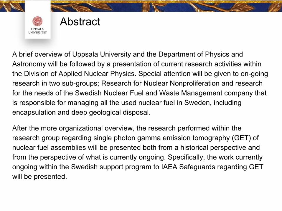
Abstract
A brief overview of Uppsala University and the Department of Physics and Astronomy will be followed by a presentation of current research activities within the Division of Applied Nuclear Physics. Special attention will be given to on-going research in two sub-groups; Research for Nuclear Nonproliferation and research for the needs of the Swedish Nuclear Fuel and Waste Management company that is responsible for managing all the used nuclear fuel in Sweden, including encapsulation and deep geological disposal.
After the more organizational overview, the research performed within the research group regarding single photon gamma emission tomography (GET) of nuclear fuel assemblies will be presented both from a historical perspective and from the perspective of what is currently ongoing. Specifically, the work currently ongoing within the Swedish support program to IAEA Safeguards regarding GET will be presented.
2
Outline
● Overview of…
○ Uppsala University○ ↳Disciplinary Domain of Science and Technology (Faculty)○ ↳Department of Physics and Astronomy○ ↳Division of Applied Nuclear Physics
● A focus on two research areas:
○ Nuclear fuel cycle back-end issues■ The Swedish nuclear situation■ Safety and Safeguards needs of the operator and regulating authority
○ Nonproliferation
● Gamma emission tomography
○ Tomographic principles○ History at UU○ Ongoing R&D
Acknowledgements:Some images kindly donated by Dr Anders Sjöland with The Swedish Nuclear Fuel and Waste Management company (SKB) and Prof. Gabriella Andersson, Ass. Prof. Sophie Grape, Dr Peter Andersson and Ass. Prof. Staffan Jacobsson Svärd with Uppsala University.
3
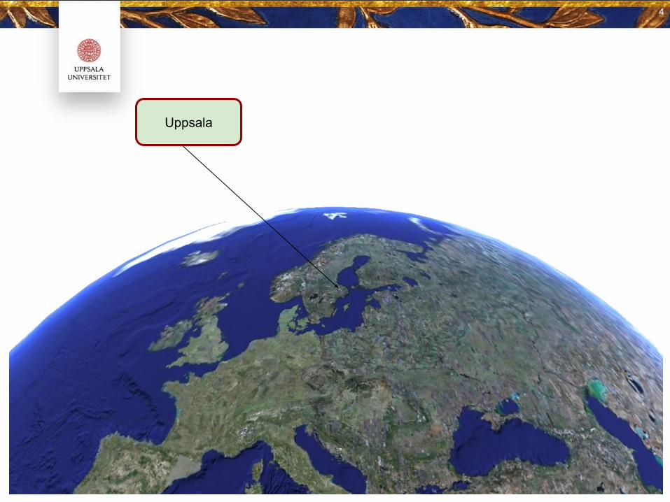
Uppsala
4
This is Uppsala University
5
5
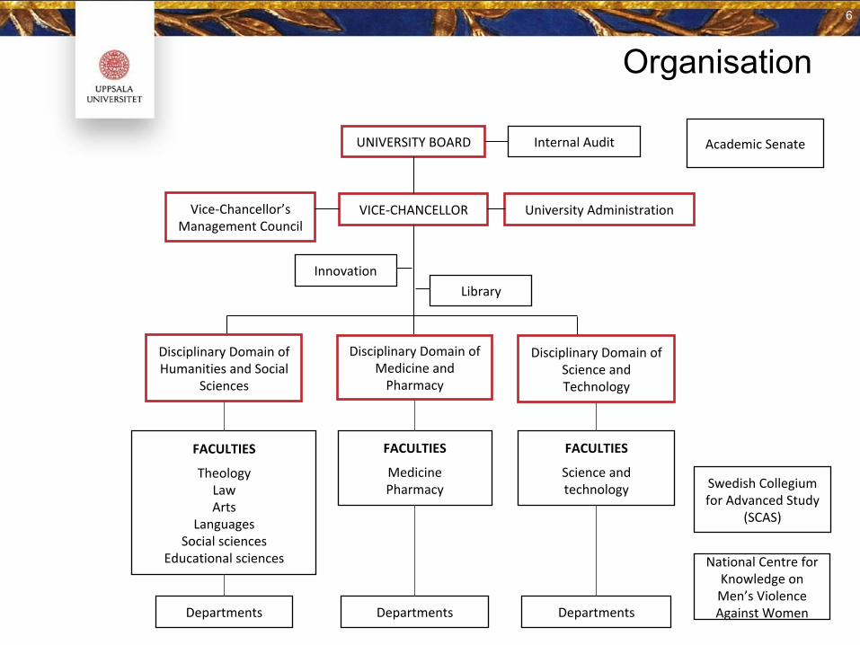
Organisation
6
6
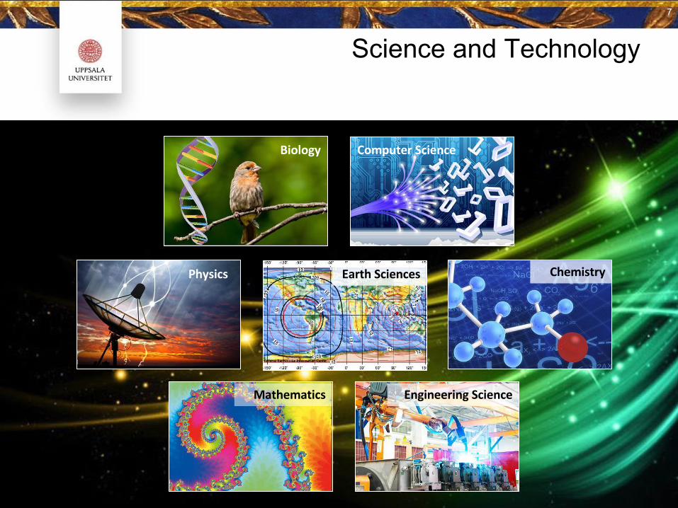
Science and Technology7
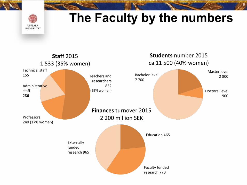
The Faculty by the numbers
8
8
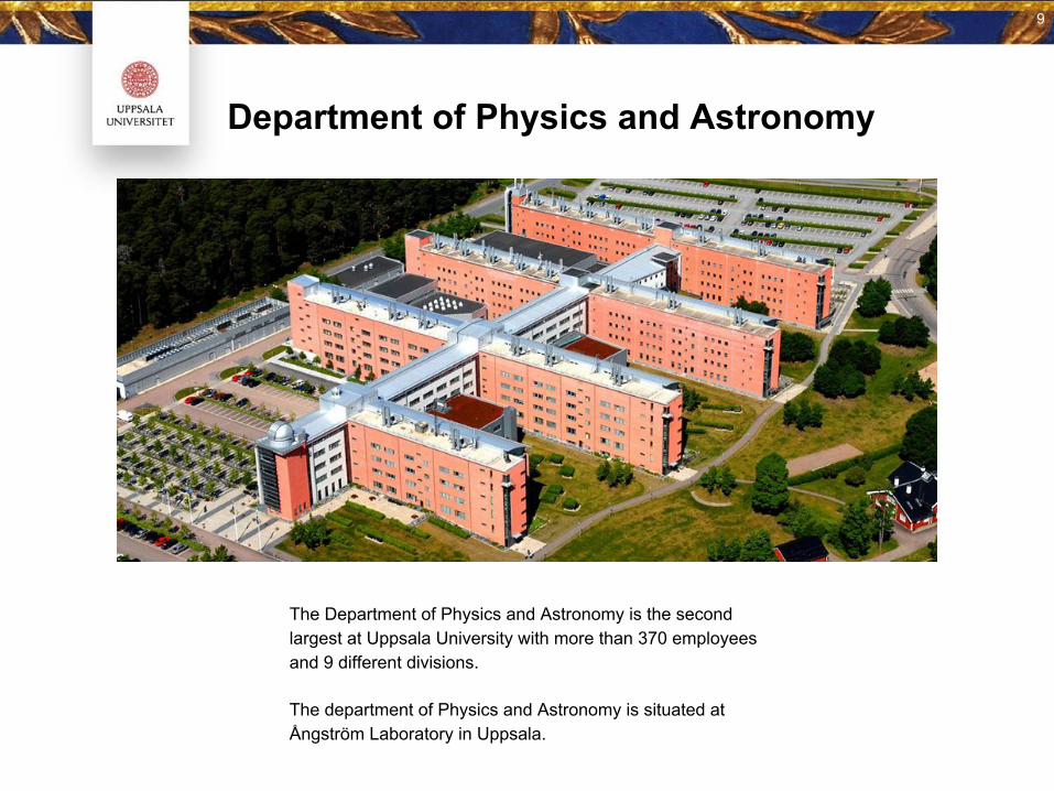
Department of Physics and Astronomy
The Department of Physics and Astronomy is the second largest at Uppsala University with more than 370 employees and 9 different divisions.
The department of Physics and Astronomy is situated at Ångström Laboratory in Uppsala.
9
10
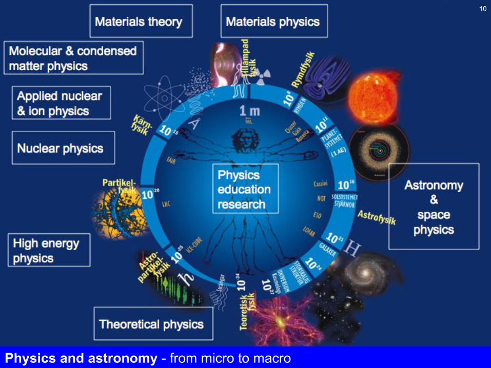
Physics and astronomy - from micro to macro
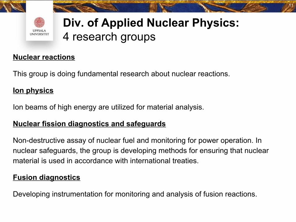
Div. of Applied Nuclear Physics:4 research groups
Nuclear reactions
This group is doing fundamental research about nuclear reactions.
Ion physics
Ion beams of high energy are utilized for material analysis.
Nuclear fission diagnostics and safeguards
Non-destructive assay of nuclear fuel and monitoring for power operation. In nuclear safeguards, the group is developing methods for ensuring that nuclear material is used in accordance with international treaties.
Fusion diagnostics
Developing instrumentation for monitoring and analysis of fusion reactions.
11
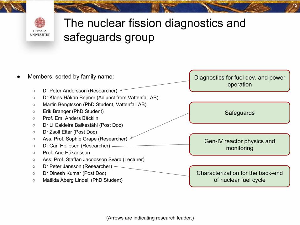
The nuclear fission diagnostics and safeguards group
● Members, sorted by family name:
○ Dr Peter Andersson (Researcher)○ Dr Klaes-Håkan Bejmer (Adjunct from Vattenfall AB)○ Martin Bengtsson (PhD Student, Vattenfall AB)○ Erik Branger (PhD Student)○ Prof. Em. Anders Bäcklin○ Dr Li Caldeira Balkeståhl (Post Doc)○ Dr Zsolt Elter (Post Doc)○ Ass. Prof. Sophie Grape (Researcher)○ Dr Carl Hellesen (Researcher)○ Prof. Ane Håkansson○ Ass. Prof. Staffan Jacobsson Svärd (Lecturer)○ Dr Peter Jansson (Researcher)○ Dr Dinesh Kumar (Post Doc)○ Matilda Åberg Lindell (PhD Student)
Characterization for the back-end of nuclear fuel cycle
Safeguards
Diagnostics for fuel dev. and power operation
Gen-IV reactor physics and monitoring
(Arrows are indicating research leader.)
12
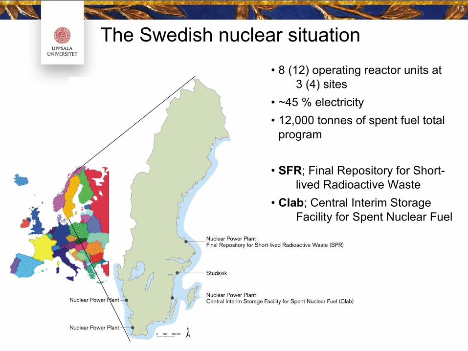
• 8 (12) operating reactor units at 3 (4) sites
• ~45 % electricity• 12,000 tonnes of spent fuel total
program
• SFR; Final Repository for Short- lived Radioactive Waste
• Clab; Central Interim Storage Facility for Spent Nuclear Fuel
The Swedish nuclear situation
13
13
14
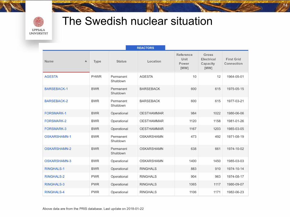
The Swedish nuclear situation
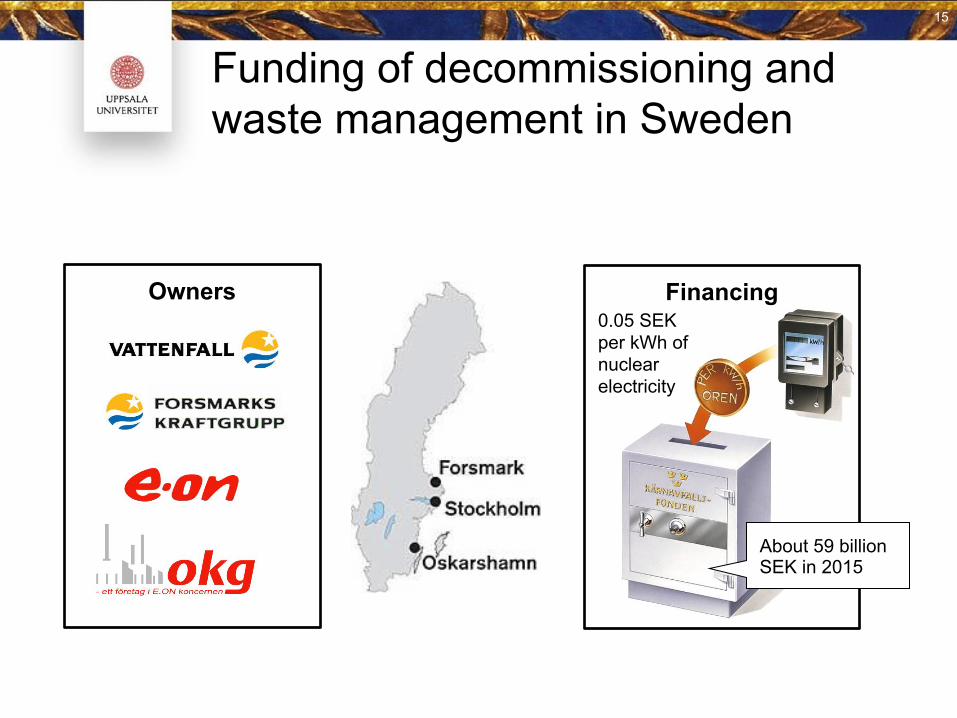
Funding of decommissioning and waste management in Sweden
About 59 billion SEK in 2015
0.05 SEK per kWh of nuclear electricity
Owners Financing
15
15
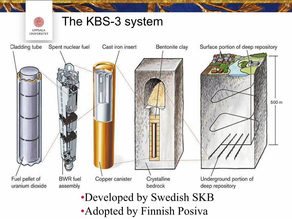
The KBS-3 system
•Developed by Swedish SKB•Adopted by Finnish Posiva
16
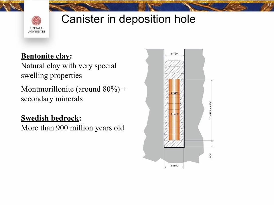
Canister in deposition hole
Bentonite clay: Natural clay with very special swelling properties
Montmorillonite (around 80%) + secondary minerals
Swedish bedrock:More than 900 million years old
17 17
17
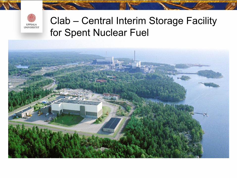
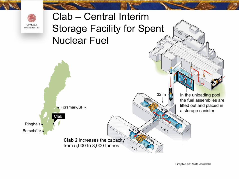
Clab – Central Interim Storage Facility for Spent Nuclear Fuel
18
Clab
Forsmark/SFR
Barsebäck
Ringhals
Clab 2 increases the capacityfrom 5,000 to 8,000 tonnes
In the unloading poolthe fuel assemblies are lifted out and placed ina storage canister
32 m
Graphic art: Mats Jerndahl
Clab – Central InterimStorage Facility for SpentNuclear Fuel
19
19
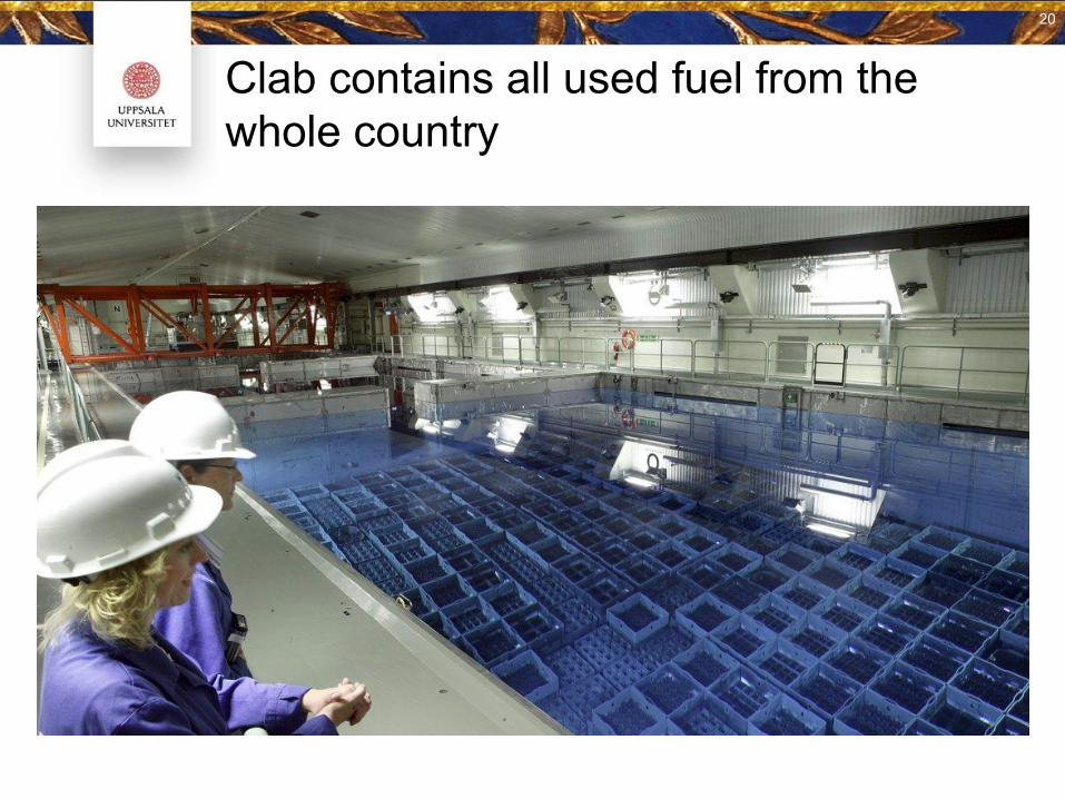
Clab contains all used fuel from the whole country
20
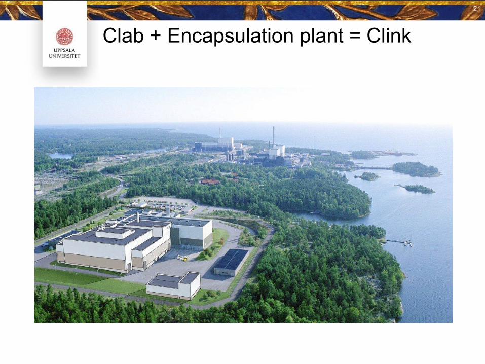
Clab + Encapsulation plant = Clink21
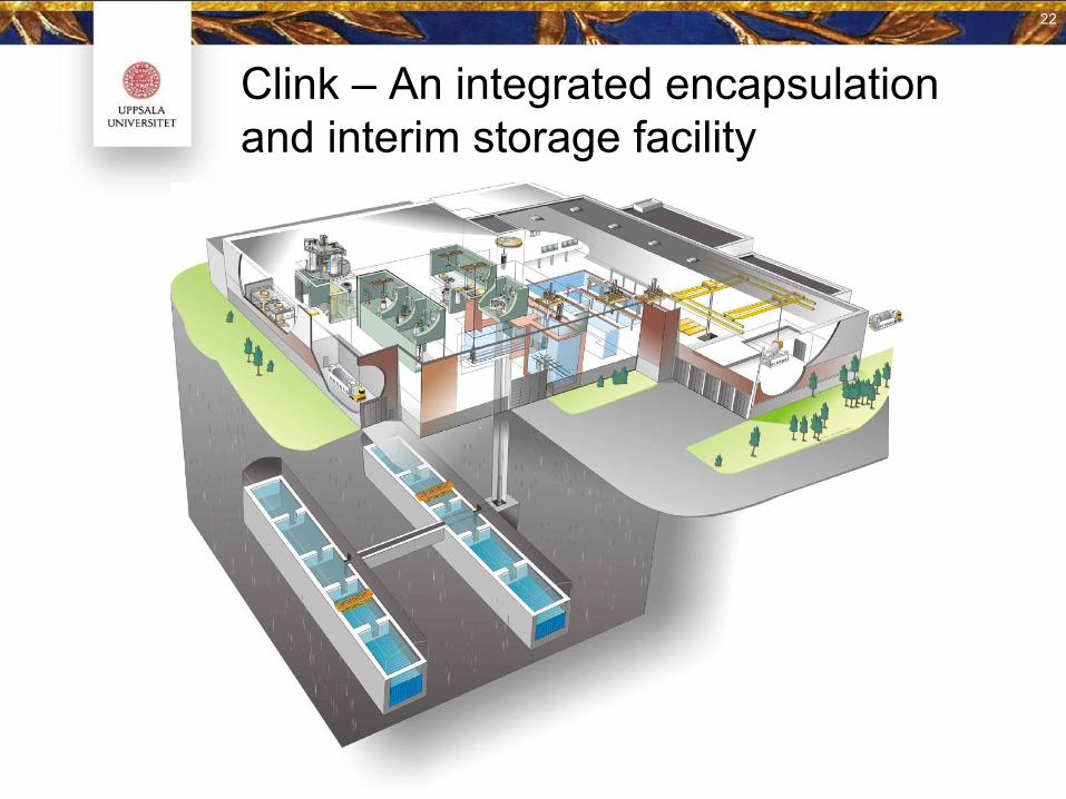
Clink – An integrated encapsulation and interim storage facility
22
22
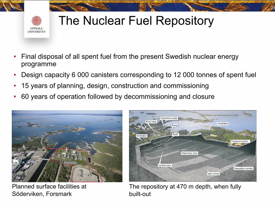
The Nuclear Fuel Repository
Planned surface facilities at Söderviken, Forsmark
23
The repository at 470 m depth, when fully built-out
• Final disposal of all spent fuel from the present Swedish nuclear energy programme
• Design capacity 6 000 canisters corresponding to 12 000 tonnes of spent fuel• 15 years of planning, design, construction and commissioning• 60 years of operation followed by decommissioning and closure
24
Typområden1977–1985
Översiktsstudier1990-tal
Förstudier1993–2002
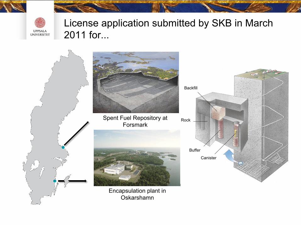
Spent Fuel Repository at Forsmark
Encapsulation plant in Oskarshamn
License application submitted by SKB in March 2011 for...
Backfill
Rock
Buffer
Canister
SKB is applying for...
• To continue interim storage of spent nuclear fuel and reactor core components. The amount of spent nuclear fuel may reach a maximum of 8000 metric tons (calculated as uranium).
• To construct and operate a facility (Clink) to store spent nuclear fuel and core components and for encapsulation of spent nuclear fuel. Capacity of approximately 200 canisters per year.
• To construct and operate a facility for final disposal of spent nuclear fuel and nuclear waste (construction material in the fuel assemblies)
– Final disposal of the spent fuel that is currently stored in Clab and
– future fuel that will arise from operating the reactors that currently have a permit to operate
• Final disposal according to the KBS-3 method with vertical placement of the canisters (KBS-3V)
• Water operations that are needed to build and operate the facilities
• Storage for rock aggregate
25
25
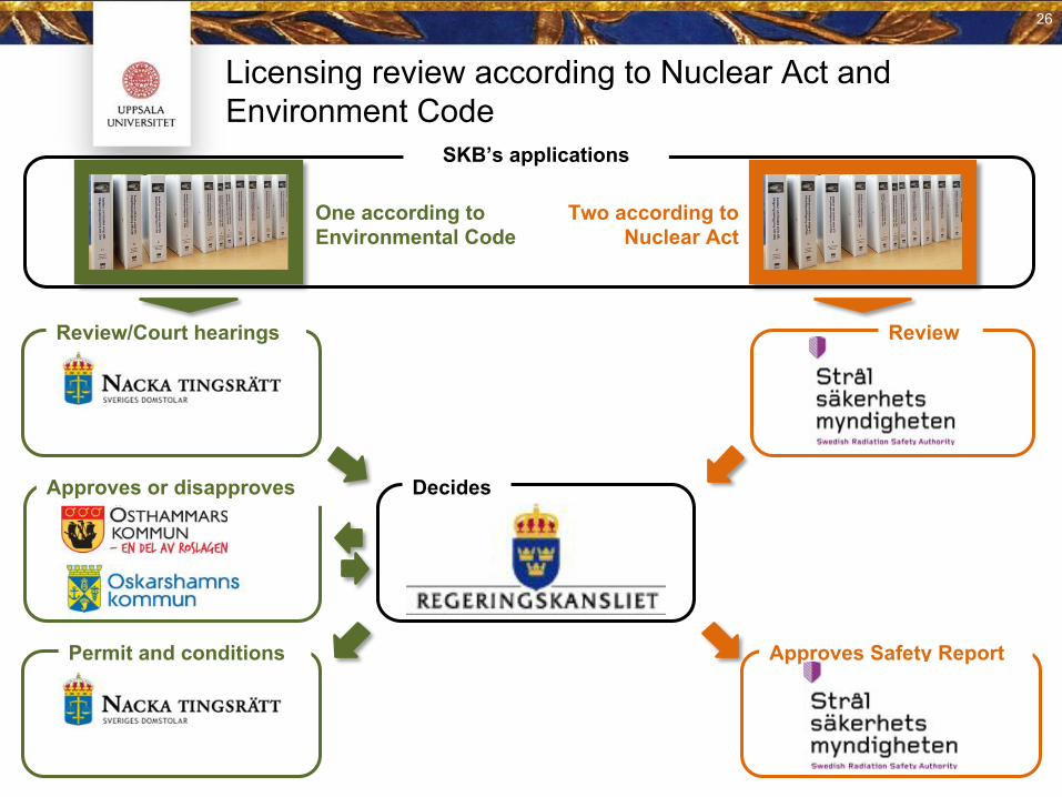
Licensing review according to Nuclear Act and Environment Code
SKB’s applications
One according to Environmental Code
Two according to Nuclear Act
Review/Court hearings Review
Decides
Permit and conditions Approves Safety Report
Approves or disapproves
26
• Decay heat – fulfil temperature requirement on canister and bentonite; optimization of repository; transport; intermediate storage pools or dry casks
• Radiation doses: gamma and neutrons; radiation protection – design, final repository, transport, intermediate storage pools or dry casks
• Criticality – multiplicity; avoid criticality everywhere at all times, final repository, transport, intermediate storage pools or dry casks
• Radionuclide inventory: goes into the long term safety analysis
• Safeguards: ○ identify correct fuel, ○ missing pins○ contents of fuel – amount of fissile material○ Burn-up (BU), Initial enrichment (IE), Cooling time (CT)
Need for back-end characterization of SNF
27
• Decay heat: very high accuracy, order of few percentage uncertainty
• Radiation doses: high accuracy – maybe 10 %
• Criticality: very high accuracy < 10 %
• Radionuclide inventory: for most nuclides fairly low accuracy need; <100 % (for some higher accuracy is needed)
• Safeguards: intermediate accuracy
Need for back-end characterization of SNF: Accuracy
28
At SKB: Various activities aiming at:
● sufficient measurement methods,● calculation codes,● fuel data and● knowledge and understanding of the nuclear fuel for
operational and safeguards issues, and● in the end for long term safety; have sufficient
competent available human resources
All to be in place at the time of start of operation of the encapsulation plant.
Fuel characterisation activities
29
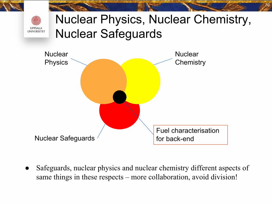
● Safeguards, nuclear physics and nuclear chemistry different aspects of same things in these respects – more collaboration, avoid division!
Nuclear Physics, Nuclear Chemistry, Nuclear Safeguards
Nuclear Physics
Nuclear Chemistry
Nuclear SafeguardsFuel characterisation for back-end
30

More about collaboration...
31
In Europe: Often relative small, under-critical, research teams.⇒ Collaboration important
Euratom: Funding via Work Programme.
Previously in RWMD: “Small, individual” EU projects. Budgets in the order of 5 M€. Call cycle every ~2 years.
Now in RWMD: One EU Joint Programme including research for deep geological disposal. ~5 year cycle. Programme budget: 52-65 M€
One R&D work package in programme, out of seven, deals with Spent Nuclear Fuel Characterization and Evolution until Disposal.
Collaboration with organisations world-wide is encouraged!
Read more: www.joprad.eu
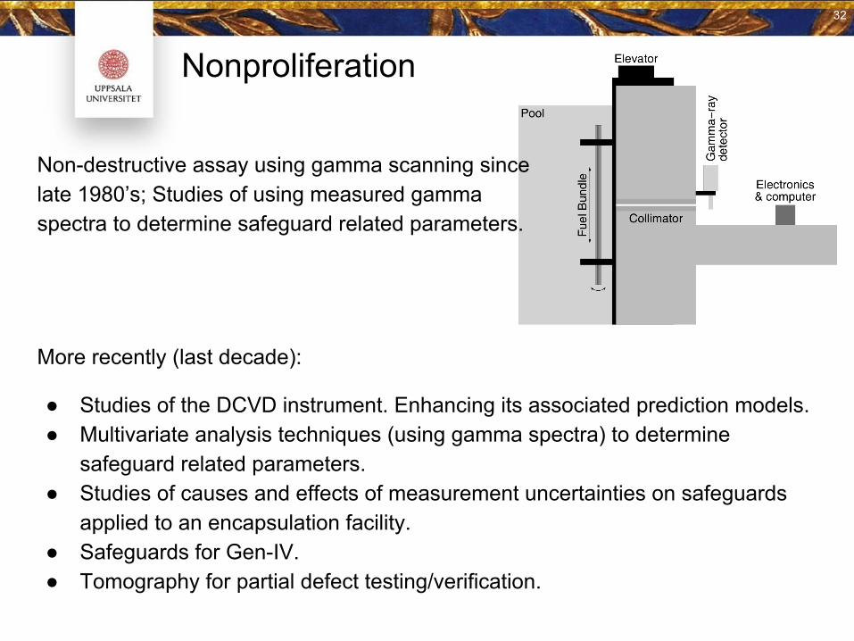
Nonproliferation
Non-destructive assay using gamma scanning since late 1980’s; Studies of using measured gamma spectra to determine safeguard related parameters.
32
More recently (last decade):
● Studies of the DCVD instrument. Enhancing its associated prediction models.● Multivariate analysis techniques (using gamma spectra) to determine
safeguard related parameters.● Studies of causes and effects of measurement uncertainties on safeguards
applied to an encapsulation facility.● Safeguards for Gen-IV.● Tomography for partial defect testing/verification.
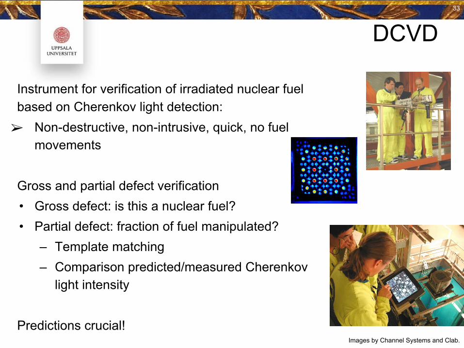
DCVD
Instrument for verification of irradiated nuclear fuel based on Cherenkov light detection:➢ Non-destructive, non-intrusive, quick, no fuel
movements
Gross and partial defect verification• Gross defect: is this a nuclear fuel?• Partial defect: fraction of fuel manipulated?
– Template matching– Comparison predicted/measured Cherenkov
light intensity
Predictions crucial!Images by Channel Systems and Clab.
33
DCVD
Multi-year effort + PhD project:• Simulations to understand and describe Cherenkov light emission from
nuclear fuel (assemblies)• Improved prediction software.
Parameterization includes IE, BU, CT, irradiation history• Possibilities offered by image analysis
Applications now include• Fast and accurate predictions • Verification of short cooled fuel• Description of and correction for near-neighbour fuel assemblies
34
34
DCVD
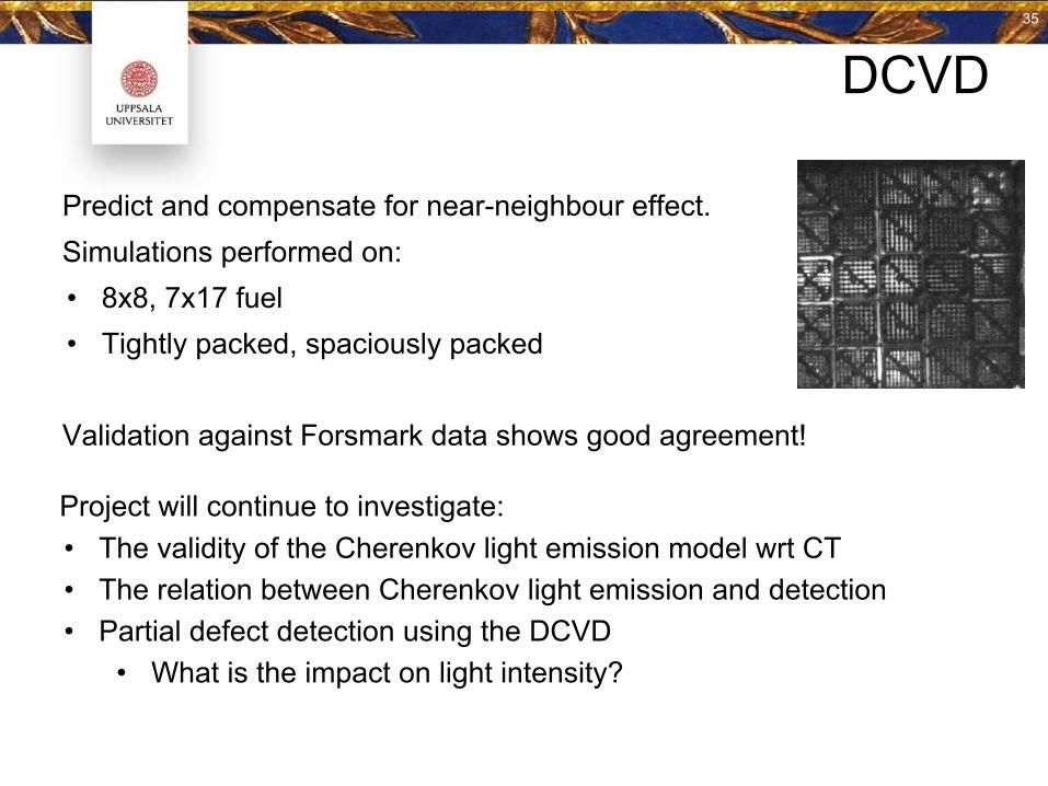
Predict and compensate for near-neighbour effect.Simulations performed on:• 8x8, 7x17 fuel• Tightly packed, spaciously packed
Validation against Forsmark data shows good agreement!
Project will continue to investigate:• The validity of the Cherenkov light emission model wrt CT• The relation between Cherenkov light emission and detection• Partial defect detection using the DCVD
• What is the impact on light intensity?
35
35
Multivariate Analysis
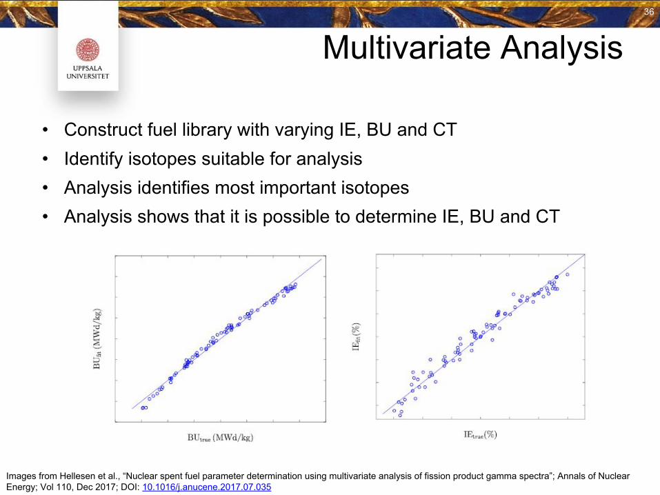
• Construct fuel library with varying IE, BU and CT• Identify isotopes suitable for analysis• Analysis identifies most important isotopes• Analysis shows that it is possible to determine IE, BU and CT
Images from Hellesen et al., “Nuclear spent fuel parameter determination using multivariate analysis of fission product gamma spectra”; Annals of Nuclear Energy; Vol 110, Dec 2017; DOI: 10.1016/j.anucene.2017.07.035 36
36
Multivariate Analysis
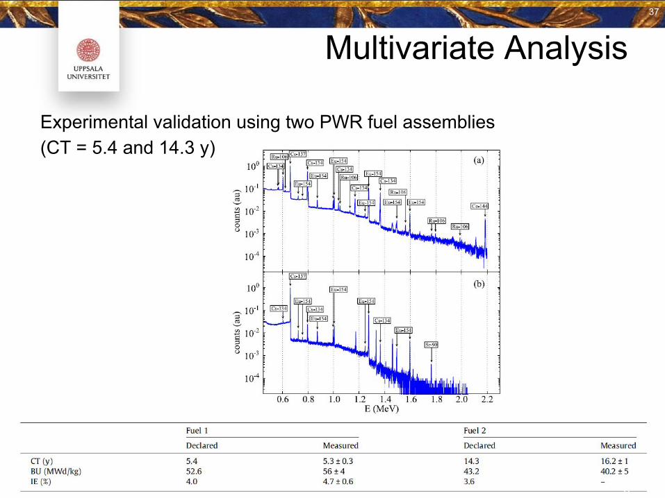
Experimental validation using two PWR fuel assemblies(CT = 5.4 and 14.3 y)
37
37
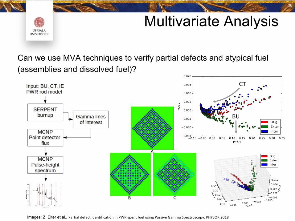
Multivariate Analysis
Can we use MVA techniques to verify partial defects and atypical fuel (assemblies and dissolved fuel)?
Images: Z. Elter et al., 38
38
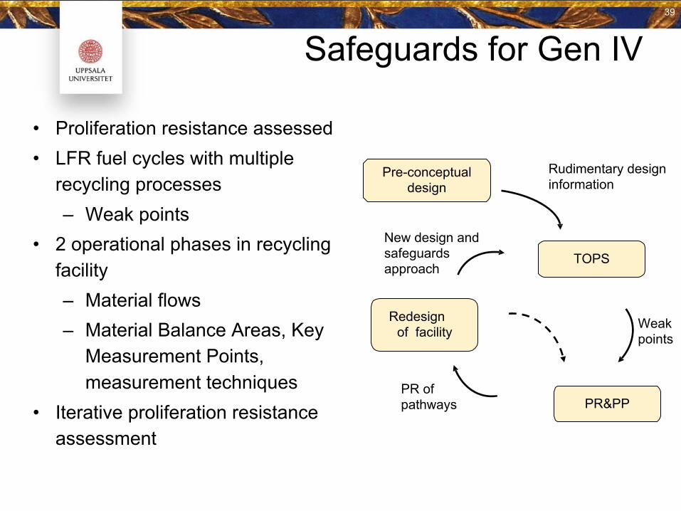
Safeguards for Gen IV
• Proliferation resistance assessed• LFR fuel cycles with multiple
recycling processes– Weak points
• 2 operational phases in recycling facility – Material flows– Material Balance Areas, Key
Measurement Points, measurement techniques
• Iterative proliferation resistance assessment
Pre-conceptual design
TOPS
PR&PP
Redesignof facility
PR of pathways
New design and safeguards approach
Rudimentary designinformation
Weak points
39
39
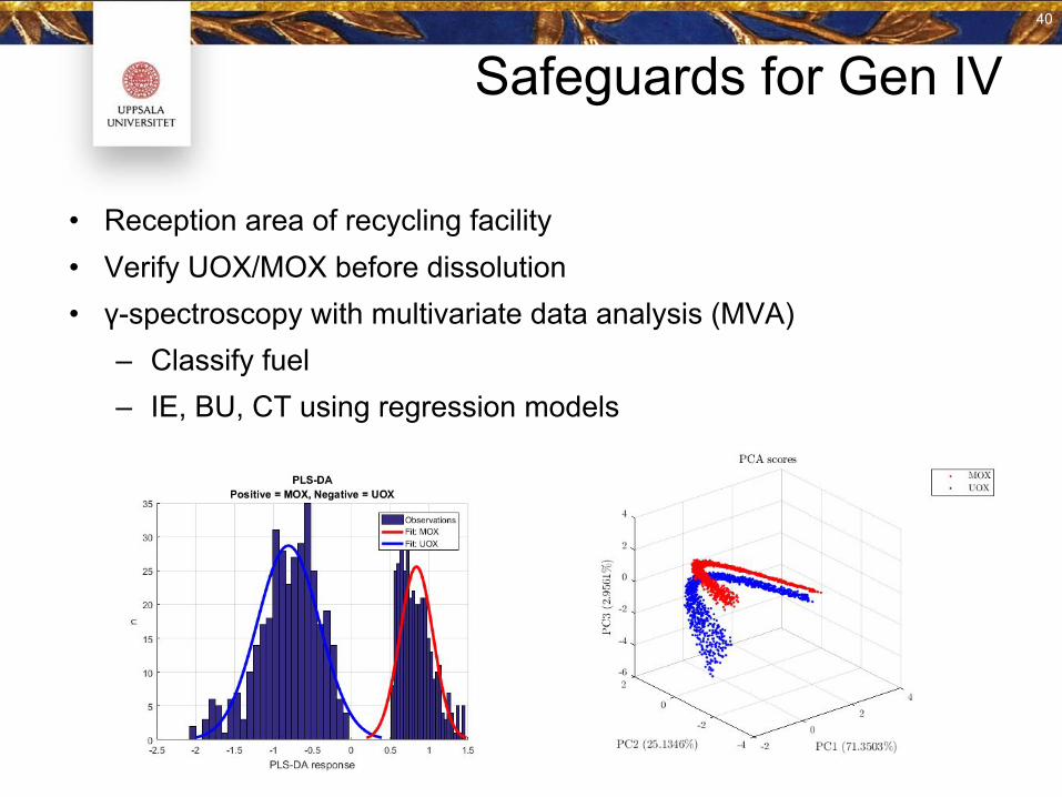
Safeguards for Gen IV
• Reception area of recycling facility• Verify UOX/MOX before dissolution• γ-spectroscopy with multivariate data analysis (MVA)
– Classify fuel– IE, BU, CT using regression models
40
40
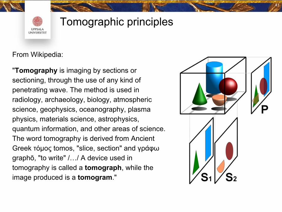
From Wikipedia:
"Tomography is imaging by sections or sectioning, through the use of any kind of penetrating wave. The method is used in radiology, archaeology, biology, atmospheric science, geophysics, oceanography, plasma physics, materials science, astrophysics, quantum information, and other areas of science. The word tomography is derived from Ancient Greek τόμος tomos, "slice, section" and γράφω graphō, "to write" /…/ A device used in tomography is called a tomograph, while the image produced is a tomogram."
Tomographic principles
41
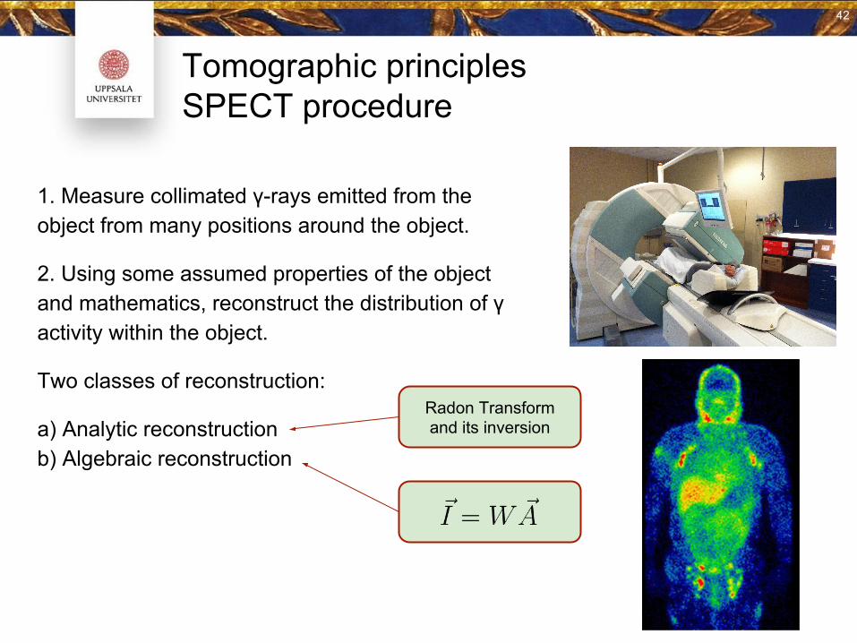
Tomographic principlesSPECT procedure
1. Measure collimated γ-rays emitted from the object from many positions around the object.
2. Using some assumed properties of the object and mathematics, reconstruct the distribution of γ activity within the object.
Two classes of reconstruction:
a) Analytic reconstruction b) Algebraic reconstruction
Radon Transform and its inversion
42
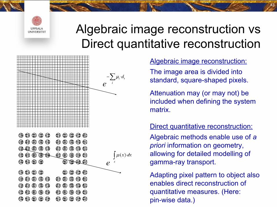
Algebraic image reconstruction vsDirect quantitative reconstruction
Direct quantitative reconstruction:Algebraic methods enable use of a priori information on geometry, allowing for detailed modelling of gamma-ray transport.
Adapting pixel pattern to object also enables direct reconstruction of quantitative measures. (Here: pin-wise data.)
Algebraic image reconstruction:The image area is divided into standard, square-shaped pixels.
Attenuation may (or may not) be included when defining the system matrix.
43
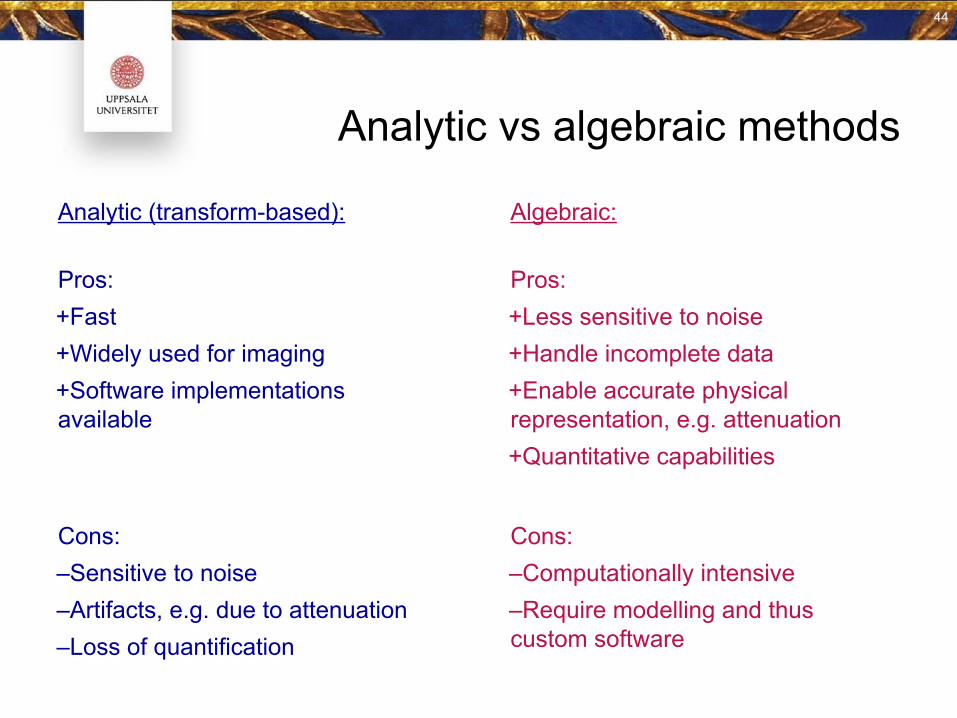
Analytic vs algebraic methods
Analytic (transform-based): Algebraic:
Pros:+Fast+Widely used for imaging+Software implementations available
Cons:‒Sensitive to noise‒Artifacts, e.g. due to attenuation‒Loss of quantification
Pros:+Less sensitive to noise+Handle incomplete data+Enable accurate physical representation, e.g. attenuation+Quantitative capabilities
Cons:‒Computationally intensive‒Require modelling and thus custom software
44
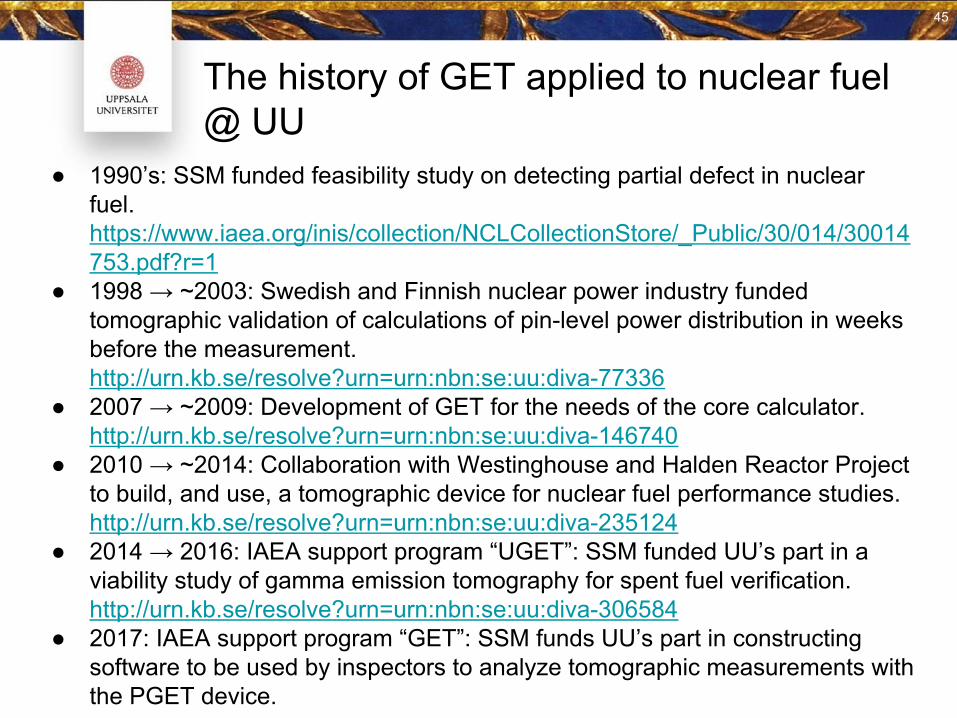
The history of GET applied to nuclear fuel @ UU
● 1990’s: SSM funded feasibility study on detecting partial defect in nuclear fuel. https://www.iaea.org/inis/collection/NCLCollectionStore/_Public/30/014/30014753.pdf?r=1
● 1998 → ~2003: Swedish and Finnish nuclear power industry funded tomographic validation of calculations of pin-level power distribution in weeks before the measurement. http://urn.kb.se/resolve?urn=urn:nbn:se:uu:diva-77336
● 2007 → ~2009: Development of GET for the needs of the core calculator. http://urn.kb.se/resolve?urn=urn:nbn:se:uu:diva-146740
● 2010 → ~2014: Collaboration with Westinghouse and Halden Reactor Project to build, and use, a tomographic device for nuclear fuel performance studies.http://urn.kb.se/resolve?urn=urn:nbn:se:uu:diva-235124
● 2014 → 2016: IAEA support program “UGET”: SSM funded UU’s part in a viability study of gamma emission tomography for spent fuel verification.http://urn.kb.se/resolve?urn=urn:nbn:se:uu:diva-306584
● 2017: IAEA support program “GET”: SSM funds UU’s part in constructing software to be used by inspectors to analyze tomographic measurements with the PGET device.
45
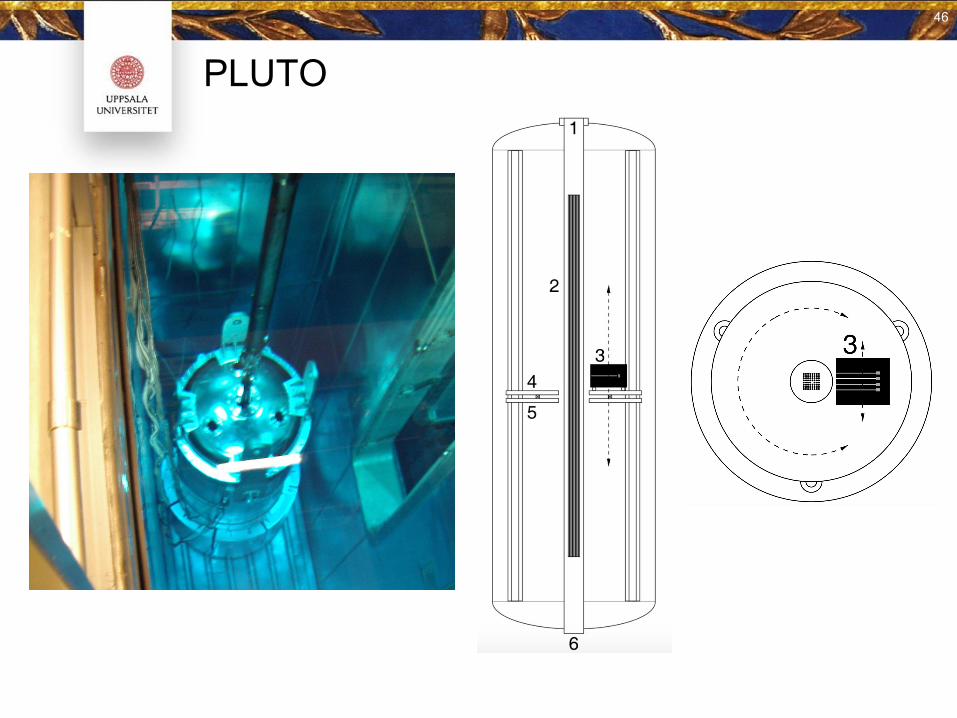
PLUTO
46
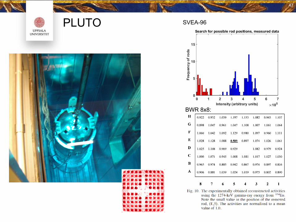
PLUTO SVEA-96
BWR 8x8:
47
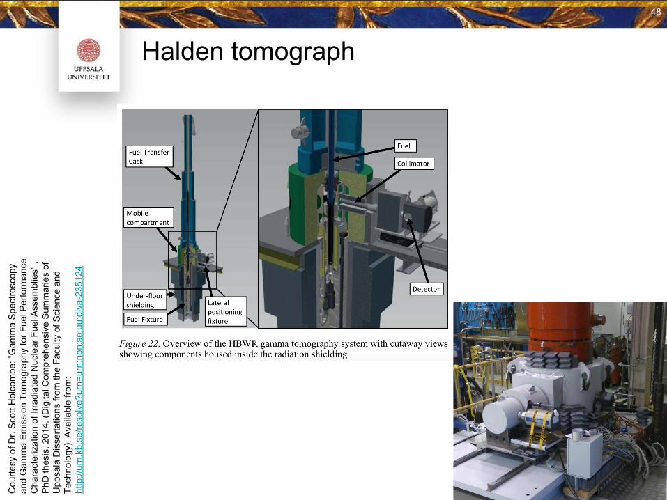
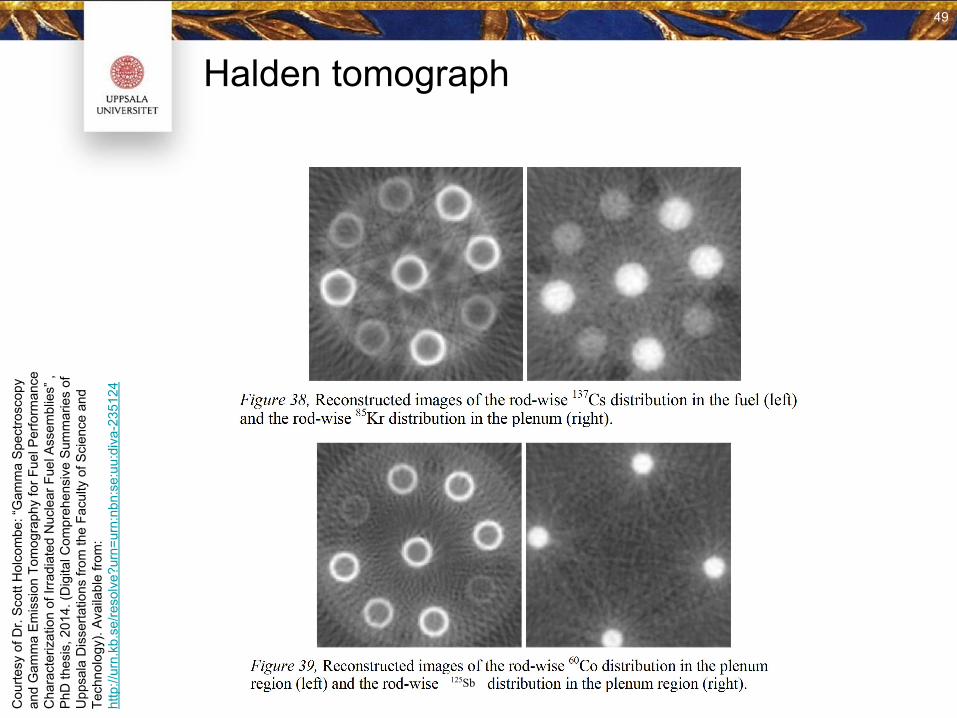
Halden tomograph
Cou
rtesy
of D
r. S
cott
Hol
com
be: “
Gam
ma
Spe
ctro
scop
y an
d G
amm
a E
mis
sion
Tom
ogra
phy
for F
uel P
erfo
rman
ce
Cha
ract
eriz
atio
n of
Irra
diat
ed N
ucle
ar F
uel A
ssem
blie
s” ,
PhD
thes
is, 2
014.
(Dig
ital C
ompr
ehen
sive
Sum
mar
ies
of
Upp
sala
Dis
serta
tions
from
the
Facu
lty o
f Sci
ence
and
Te
chno
logy
). A
vaila
ble
from
: ht
tp://
urn.
kb.s
e/re
solv
e?ur
n=ur
n:nb
n:se
:uu:
diva
-235
124
48
Halden tomograph
Cou
rtesy
of D
r. S
cott
Hol
com
be: “
Gam
ma
Spe
ctro
scop
y an
d G
amm
a E
mis
sion
Tom
ogra
phy
for F
uel P
erfo
rman
ce
Cha
ract
eriz
atio
n of
Irra
diat
ed N
ucle
ar F
uel A
ssem
blie
s” ,
PhD
thes
is, 2
014.
(Dig
ital C
ompr
ehen
sive
Sum
mar
ies
of
Upp
sala
Dis
serta
tions
from
the
Facu
lty o
f Sci
ence
and
Te
chno
logy
). A
vaila
ble
from
: ht
tp://
urn.
kb.s
e/re
solv
e?ur
n=ur
n:nb
n:se
:uu:
diva
-235
124
125Sb
49
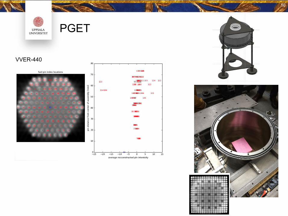
PGET
VVER-440
50
Ongoing GET research at UU
● Halden Reactor Project: LOCA tests(high power → rod ballooning → fragmentation)
○ Axial scanning of rods + tomography of rods○ Development of reconstruction techniques
● IAEA Support:○ Software for determining rod positions and fuel assembly position from tomographic images○ Software for algebraic reconstruction○ ⇒ Components in the IAEA “GET toolbox”
● Now at PNNL:○ Learning RADSAT and applying it to “hard Monte Carlo problems” ○ Exploring challenging situations for tomography with
(high burnup, short cooling time) or (low burnup, long cooling time)
51
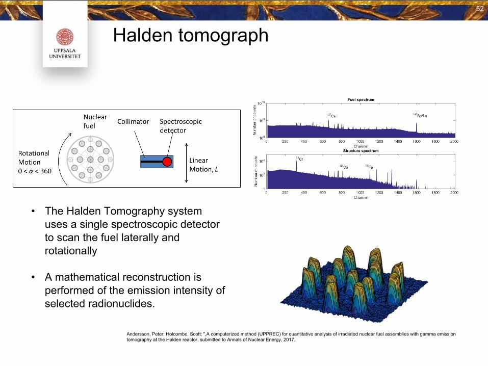
Halden tomograph
• The Halden Tomography system uses a single spectroscopic detector to scan the fuel laterally and rotationally
• A mathematical reconstruction is performed of the emission intensity of selected radionuclides.
Andersson, Peter; Holcombe, Scott; ",A computerized method (UPPREC) for quantitative analysis of irradiated nuclear fuel assemblies with gamma emission tomography at the Halden reactor, submitted to Annals of Nuclear Energy, 2017,
52
52
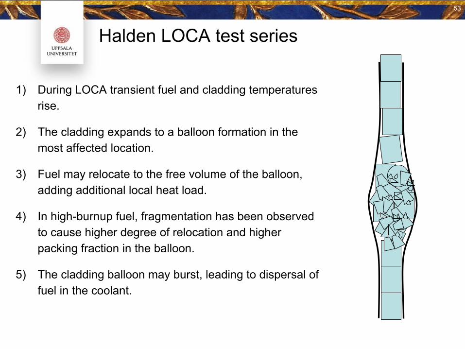
Halden LOCA test series
1) During LOCA transient fuel and cladding temperatures rise.
2) The cladding expands to a balloon formation in the most affected location.
3) Fuel may relocate to the free volume of the balloon, adding additional local heat load.
4) In high-burnup fuel, fragmentation has been observed to cause higher degree of relocation and higher packing fraction in the balloon.
5) The cladding balloon may burst, leading to dispersal of fuel in the coolant.
53
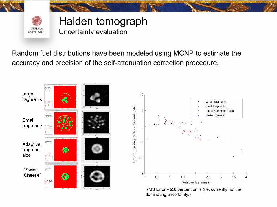
Halden tomographUncertainty evaluation
Random fuel distributions have been modeled using MCNP to estimate the accuracy and precision of the self-attenuation correction procedure.
54
RMS Error = 2.6 percent units (i.e. currently not the dominating uncertainty.)
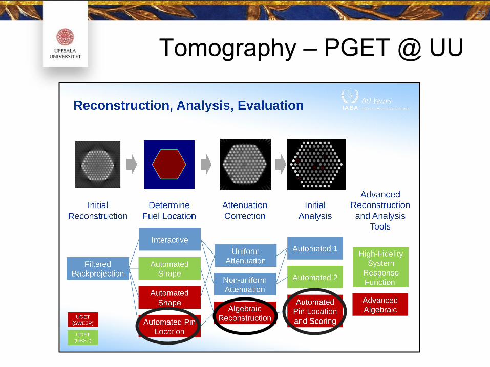
Tomography – PGET @ UU55
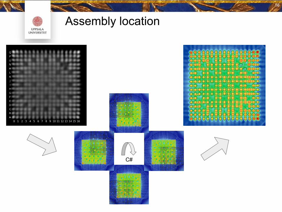
Assembly location
56
56
C#
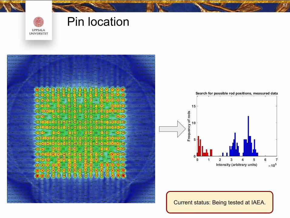
Pin location
57
57
Current status: Being tested at IAEA.
Algebraic reconstruction software development
● Object oriented (C++)
⇒ Abstract base for generic algebraic reconstruction
○ Pixels of any shape○ Arbitrarily shaped collimator- and detector system○ Arbitrarily shaped measurement objects (fuel assemblies)○ Generic gamma-ray transport
● Initially specialized:
○ PGET geometry and materials○ “Photo peak ray tracing” with attenuation○ Intrinsic instrument response (without measurement object) calculated with MCNP.
58
Current status: Work In Progress
Thank you for your attention!
59