Embed Size (px)
Citation preview
North American Combustion Burners
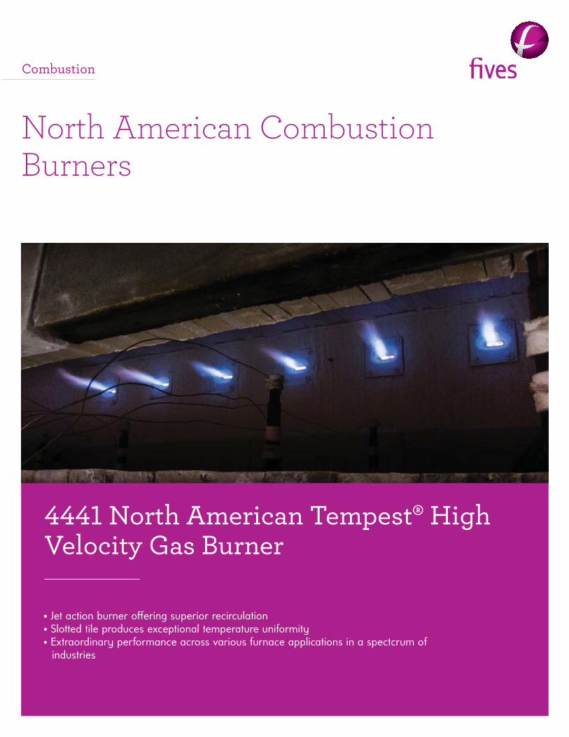
4441 North American Tempest® High Velocity Gas Burner
• Jet action burner off ering superior recirculation• Slotted tile produces exceptional temperature uniformity• Extraordinary performance across various furnace applications in a spectcrum of
industries
Combustion
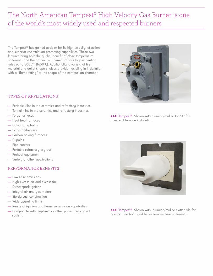
4441 Tempest®. Shown with alumina/mullite tile "A" for fi ber wall furnace installation.
4441 Tempest®. Shown with alumina/mullite slotted tile for narrow lane fi ring and better temperature uniformity.
The North American Tempest® High Velocity Gas Burner is one of the world’s most widely used and respected burners
The Tempest® has gained acclaim for its high velocity jet action and superior recirculation promoting capabilities. These two features bring both the quality benefi t of close temperature uniformity and the productivity benefi t of safe higher heating rates up to 3000°F (1650°C). Additionally, a variety of tile material and outlet shape choices provide fl exibility in installation with a “fl ame fi tting” to the shape of the combustion chamber.
TYPES OF APPLICATIONS
— Periodic kilns in the ceramics and refractory industries— Tunnel kilns in the ceramics and refractory industries— Forge furnaces— Heat treat furnaces— Galvanizing baths— Scrap preheaters— Carbon baking furnaces— Cupolas— Pipe coaters— Portable refractory dry out— Preheat equipment— Variety of other applications
PERFORMANCE BENEFITS
— Low NOx emissions— High excess air and excess fuel— Direct spark ignition— Integral air and gas meters— Sturdy cast construction— Wide operating limits— Range of ignition and fl ame supervision capabilities— Compatible with StepFire™ or other pulse fi red control system.
Imperial 4441 Natural Gas Performance Data(Performance for 27.7"w.c main air pressure operating at stoichiometric ratio unless stated otherwise)
— Combustion Air: 0.3-41.6"w.c. (0.08-10.3 kPa) air pressure, max 350°F (177°C).
— Fuel: Natural gas with propane gas versions available in the -1 thru -4-B sizes. Gas pressure varies per size with 19"w.c. (4.7 kPa) is maximum required at design capacity, for 27.7"w.c. (6.9 KPA) combustion air pressure, stoich ratio.
— Flame Supervision: Flame rod or UV detector Consult National Safety Standards and insurance underwriters for specifi c fl ame supervision requirements. Flame supervisory components must be ordered separately. See Section 7.1 for correct fl ame rod part number.
— Ignition: Direct spark (no pilot) with 6000 V transformer. A halfwave transformer prevents UV sensing of the spark during trial for ignition. Lighting not recommended above 27.7"w.c. (6.9 kPa) main air pressure. Excess air required for ignition.
— Control: Excellent performance with all control systems; StepFire™, on-ratio and thermal turndown. A limiting orifi ce valve must be installed in gas supply line within 1 ft . (30 cm) of burner. A ratio regulator should be within 4 ft . (122 cm) of burner.
— Relight: Tempest® burners require spark for re-ignition. They will not relight from a hot tile or furnace.
— Piping: For cross-connected systems, maximum gas pressure at the burner can be adversely impacted by excessive pressure drop in the gas line between the ratio regulator and the burner. The design, selection, and installation of these systems must take into account the gas pressure required at the burner to achieve the desired heat release (i.e. gas fl ow). For more detailed information on cross-con- nected control systems, see section 4.1.
North American Tempest® High Velocity Gas Burner Performance Data
— Capacities of the burners have not changed. Imperial units of static pressure are now given in inches of water column.
Burner Size -1 -2 -3 -4-A -4-B -5 -6 -7 -8-A -8-B -8-C
Air Flow, not burning (scfh) 1600 2700 4000 6100 8200 11000 19000 26000 36000 50000 63000
Air Flow, (scfh)xxxx 1250 2200 3300 5250 6900 9500 15000 22000 31000 42000 54000
Air Orifi ce , UA-DA, ("w.c.) 13.2 16.6 17.4 16.4 16.5 15.5 7.3 7.1 13.8 11.9 8.3
Gas Orifi ce , UG-DG ("w.c.) 3.9 6.7 8.5 7.9 8.5 2.9 2.6 3.8 2.5 4.6 7.3
Gas Pressure UG ("w.c.) 10.4 9.5 9.9 8.8 9.1 7.2 9.0 7.0 5.8 7.7 7.8
Gas Pressure UG ("w.c.), 30% XSF 12.0 14.0 13.5 11.9 12.7 8.0 9.9 7.7 7.5 9.5 10.1
Max. % XSA, (ignition and fl ame signal limit) 2000 3000 4000 6000 6000 6000 6000 6000 3000 3000 3000
Max. % XSF, (ignition and fl ame signal limit) 30 30 30 30 30 30 30 30 30 30 30
Flame Length (in.)x 10 10 12 20 26 28 36 45 50 60 68
F lame Diameter (in.) 1 2 2 3 4 6 7 8 12 14 14
Imperial 4441 Propane Gas Performance Data(Performance for 27.7"w.c main air pressure operating at stoichiometric ratio unless stated otherwise)
Burner Size -1 -2 -3 -4-A -4-B
Air Flow, not burning (scfh)xxxxxxxxxxxxxx 1700 2700 3850 6200 8600
Air Flow, (scfh)xxxxxxxxxxxxxxxxxxxxxxxxx 1350 2200 3450 5350 7600
Air Orifi ce , UA-DA, ("w.c.)xxxxxxxxxxxxx 13.2 15.3 18.7 16.5 15.9
Gas Orifi ce , UG-DG ("w.c.)xxxxxxxxxxxxx 1.9 3.2 8.3 3.2 4.5
Gas Pressure UG ("w.c.)xxxxxxxxxxxxxxxxxx 9.2 8.3 9.2 6.6 7.0
Gas Pressure UG ("w.c.), 30% XSFxxxxxxxxx 9.6 8.7 14 7.8 8.7
Max. % XSA, (igniton and fl ame signal limit) 1000 2000 3300 1750 2800
Max. % XSF, (ignition and fl ame signal limit) 30 30 30 30 30
Flame Length (in.)xxxxxxxxxxxxxxxxxxxxxx 8 15 12 24 24
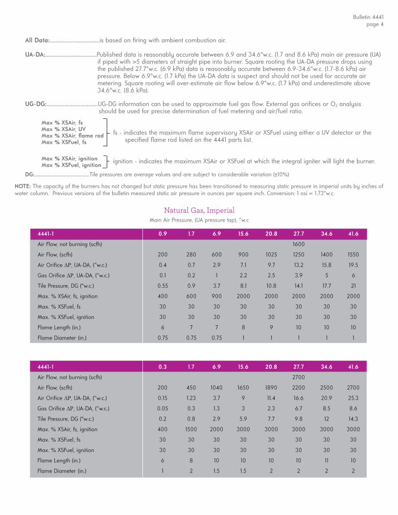
All Data:...............................is based on fi ring with ambient combustion air.
UA-DA:................................Published data is reasonably accurate between 6.9 and 34.6"w.c. (1.7 and 8.6 kPa) main air pressure (UA) if piped with >5 diameters of straight pipe into burner. Square rooting the UA-DA pressure drops using the published 27.7"w.c. (6.9 kPa) data is reasonably accurate between 6.9-34.6"w.c. (1.7-8.6 kPa) air pressure. Below 6.9"w.c. (1.7 kPa) the UA-DA data is suspect and should not be used for accurate air metering. Square rooting will over-estimate air fl ow below 6.9"w.c. (1.7 kPa) and underestimate above 34.6"w.c. (8.6 kPa).
UG-DG:................................UG-DG information can be used to approximate fuel gas fl ow. External gas orifi ces or O2 analysis should be used for precise determination of fuel metering and air/fuel ratio.
fs - indicates the maximum fl ame supervisory XSAir or XSFuel using either a UV detector or the specifi ed fl ame rod listed on the 4441 parts list.
ignition - indicates the maximum XSAir or XSFuel at which the integral igniter will light the burner.
DG:......................................Tile pressures are average values and are subject to considerable variation (±10%)
Max % XSAir, fsMax % XSAir, UVMax % XSAir, fl ame rodMax % XSFuel, fs
Max % XSAir, ignitionMax % XSFuel, ignition
Natural Gas, ImperialMain Air Pressure, (UA pressure tap), "w.c
NOTE: The capacity of the burners has not changed but static pressure has been transitioned to measuring static pressure in imperial units by inches of water column. Previous versions of the bulletin measured static air pressure in ounces per square inch. Conversion: 1 osi = 1.73"w.c.
Bulletin 4441page 4
4441-1 0.9 1.7 6.9 15.6 20.8 27.7 34.6 41.6
Air Flow, not burning (scfh) 1600
Air Flow, (scfh) 200 280 600 900 1025 1250 1400 1550
Air Orifi ce , UA-DA, (“w.c.) 0.4 0.7 2.9 7.1 9.7 13.2 15.8 19.5
Gas Orifi ce , UA-DA, (“w.c.) 0.1 0.2 1 2.2 2.5 3.9 5 6
Tile Pressure, DG ("w.c.) 0.55 0.9 3.7 8.1 10.8 14.1 17.7 21
Max. % XSAir, fs, ignition 400 600 900 2000 2000 2000 2000 2000
Max. % XSFuel, fs 30 30 30 30 30 30 30 30
Max. % XSFuel, ignition 30 30 30 30 30 30 30 30
Flame Length (in.) 6 7 7 8 9 10 10 10
Flame Diameter (in.) 0.75 0.75 0.75 1 1 1 1 1
4441-1 0.3 1.7 6.9 15.6 20.8 27.7 34.6 41.6
Air Flow, not burning (scfh) 2700
Air Flow, (scfh) 200 450 1040 1650 1890 2200 2500 2700
Air Orifi ce , UA-DA, (“w.c.) 0.15 1.23 3.7 9 11.4 16.6 20.9 25.3
Gas Orifi ce , UA-DA, (“w.c.) 0.05 0.3 1.3 3 2.3 6.7 8.5 8.6
Tile Pressure, DG ("w.c.) 0.2 0.8 2.9 5.9 7.7 9.8 12 14.3
Max. % XSAir, fs, ignition 400 1500 2000 3000 3000 3000 3000 3000
Max. % XSFuel, fs 30 30 30 30 30 30 30 30
Max. % XSFuel, ignition 30 30 30 30 30 30 30 30
Flame Length (in.) 6 8 10 10 10 10 11 10
Flame Diameter (in.) 1 2 1.5 1.5 2 2 2 2
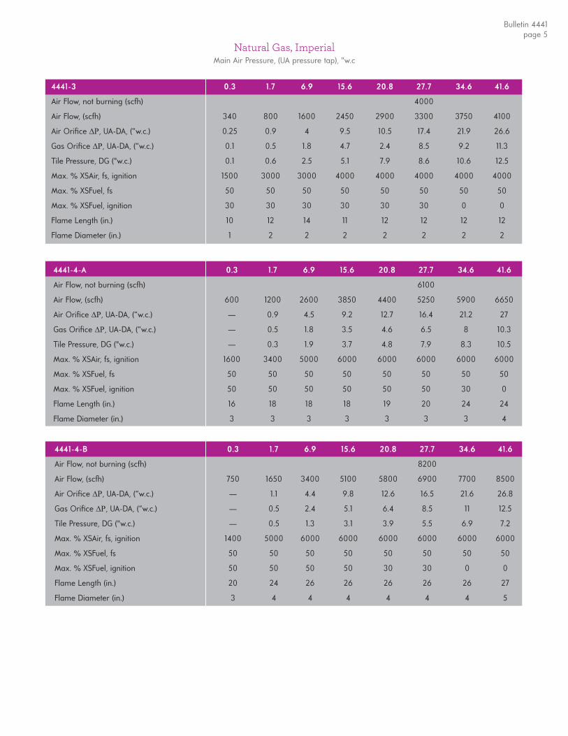
Natural Gas, ImperialMain Air Pressure, (UA pressure tap), "w.c
Bulletin 4441page 5
4441-3 0.3 1.7 6.9 15.6 20.8 27.7 34.6 41.6
Air Flow, not burning (scfh) 4000
Air Flow, (scfh) 340 800 1600 2450 2900 3300 3750 4100
Air Orifi ce , UA-DA, (“w.c.) 0.25 0.9 4 9.5 10.5 17.4 21.9 26.6
Gas Orifi ce , UA-DA, (“w.c.) 0.1 0.5 1.8 4.7 2.4 8.5 9.2 11.3
Tile Pressure, DG ("w.c.) 0.1 0.6 2.5 5.1 7.9 8.6 10.6 12.5
Max. % XSAir, fs, ignition 1500 3000 3000 4000 4000 4000 4000 4000
Max. % XSFuel, fs 50 50 50 50 50 50 50 50
Max. % XSFuel, ignition 30 30 30 30 30 30 0 0
Flame Length (in.) 10 12 14 11 12 12 12 12
Flame Diameter (in.) 1 2 2 2 2 2 2 2
4441-4-A 0.3 1.7 6.9 15.6 20.8 27.7 34.6 41.6
Air Flow, not burning (scfh) 6100
Air Flow, (scfh) 600 1200 2600 3850 4400 5250 5900 6650
Air Orifi ce , UA-DA, (“w.c.) — 0.9 4.5 9.2 12.7 16.4 21.2 27
Gas Orifi ce , UA-DA, (“w.c.) — 0.5 1.8 3.5 4.6 6.5 8 10.3
Tile Pressure, DG ("w.c.) — 0.3 1.9 3.7 4.8 7.9 8.3 10.5
Max. % XSAir, fs, ignition 1600 3400 5000 6000 6000 6000 6000 6000
Max. % XSFuel, fs 50 50 50 50 50 50 50 50
Max. % XSFuel, ignition 50 50 50 50 50 50 30 0
Flame Length (in.) 16 18 18 18 19 20 24 24
Flame Diameter (in.) 3 3 3 3 3 3 3 4
4441-4-B 0.3 1.7 6.9 15.6 20.8 27.7 34.6 41.6
Air Flow, not burning (scfh) 8200
Air Flow, (scfh) 750 1650 3400 5100 5800 6900 7700 8500
Air Orifi ce , UA-DA, (“w.c.) — 1.1 4.4 9.8 12.6 16.5 21.6 26.8
Gas Orifi ce , UA-DA, (“w.c.) — 0.5 2.4 5.1 6.4 8.5 11 12.5
Tile Pressure, DG ("w.c.) — 0.5 1.3 3.1 3.9 5.5 6.9 7.2
Max. % XSAir, fs, ignition 1400 5000 6000 6000 6000 6000 6000 6000
Max. % XSFuel, fs 50 50 50 50 50 50 50 50
Max. % XSFuel, ignition 50 50 50 50 30 30 0 0
Flame Length (in.) 20 24 26 26 26 26 26 27
Flame Diameter (in.) 3 4 4 4 4 4 4 5
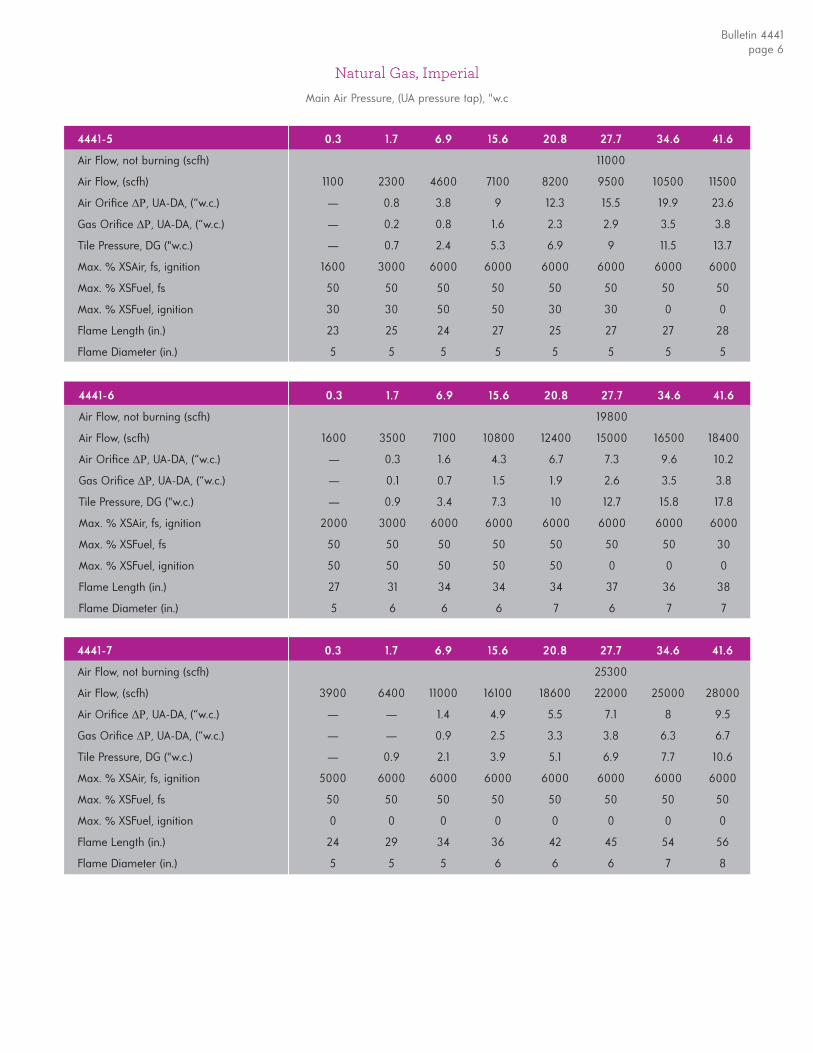
Natural Gas, ImperialMain Air Pressure, (UA pressure tap), "w.c
Bulletin 4441page 6
4441-5 0.3 1.7 6.9 15.6 20.8 27.7 34.6 41.6
Air Flow, not burning (scfh) 11000
Air Flow, (scfh) 1100 2300 4600 7100 8200 9500 10500 11500
Air Orifi ce , UA-DA, (“w.c.) — 0.8 3.8 9 12.3 15.5 19.9 23.6
Gas Orifi ce , UA-DA, (“w.c.) — 0.2 0.8 1.6 2.3 2.9 3.5 3.8
Tile Pressure, DG ("w.c.) — 0.7 2.4 5.3 6.9 9 11.5 13.7
Max. % XSAir, fs, ignition 1600 3000 6000 6000 6000 6000 6000 6000
Max. % XSFuel, fs 50 50 50 50 50 50 50 50
Max. % XSFuel, ignition 30 30 50 50 30 30 0 0
Flame Length (in.) 23 25 24 27 25 27 27 28
Flame Diameter (in.) 5 5 5 5 5 5 5 5
4441-7 0.3 1.7 6.9 15.6 20.8 27.7 34.6 41.6
Air Flow, not burning (scfh) 25300
Air Flow, (scfh) 3900 6400 11000 16100 18600 22000 25000 28000
Air Orifi ce , UA-DA, (“w.c.) — — 1.4 4.9 5.5 7.1 8 9.5
Gas Orifi ce , UA-DA, (“w.c.) — — 0.9 2.5 3.3 3.8 6.3 6.7
Tile Pressure, DG ("w.c.) — 0.9 2.1 3.9 5.1 6.9 7.7 10.6
Max. % XSAir, fs, ignition 5000 6000 6000 6000 6000 6000 6000 6000
Max. % XSFuel, fs 50 50 50 50 50 50 50 50
Max. % XSFuel, ignition 0 0 0 0 0 0 0 0
Flame Length (in.) 24 29 34 36 42 45 54 56
Flame Diameter (in.) 5 5 5 6 6 6 7 8
4441-6 0.3 1.7 6.9 15.6 20.8 27.7 34.6 41.6
Air Flow, not burning (scfh) 19800
Air Flow, (scfh) 1600 3500 7100 10800 12400 15000 16500 18400
Air Orifi ce , UA-DA, (“w.c.) — 0.3 1.6 4.3 6.7 7.3 9.6 10.2
Gas Orifi ce , UA-DA, (“w.c.) — 0.1 0.7 1.5 1.9 2.6 3.5 3.8
Tile Pressure, DG ("w.c.) — 0.9 3.4 7.3 10 12.7 15.8 17.8
Max. % XSAir, fs, ignition 2000 3000 6000 6000 6000 6000 6000 6000
Max. % XSFuel, fs 50 50 50 50 50 50 50 30
Max. % XSFuel, ignition 50 50 50 50 50 0 0 0
Flame Length (in.) 27 31 34 34 34 37 36 38
Flame Diameter (in.) 5 6 6 6 7 6 7 7
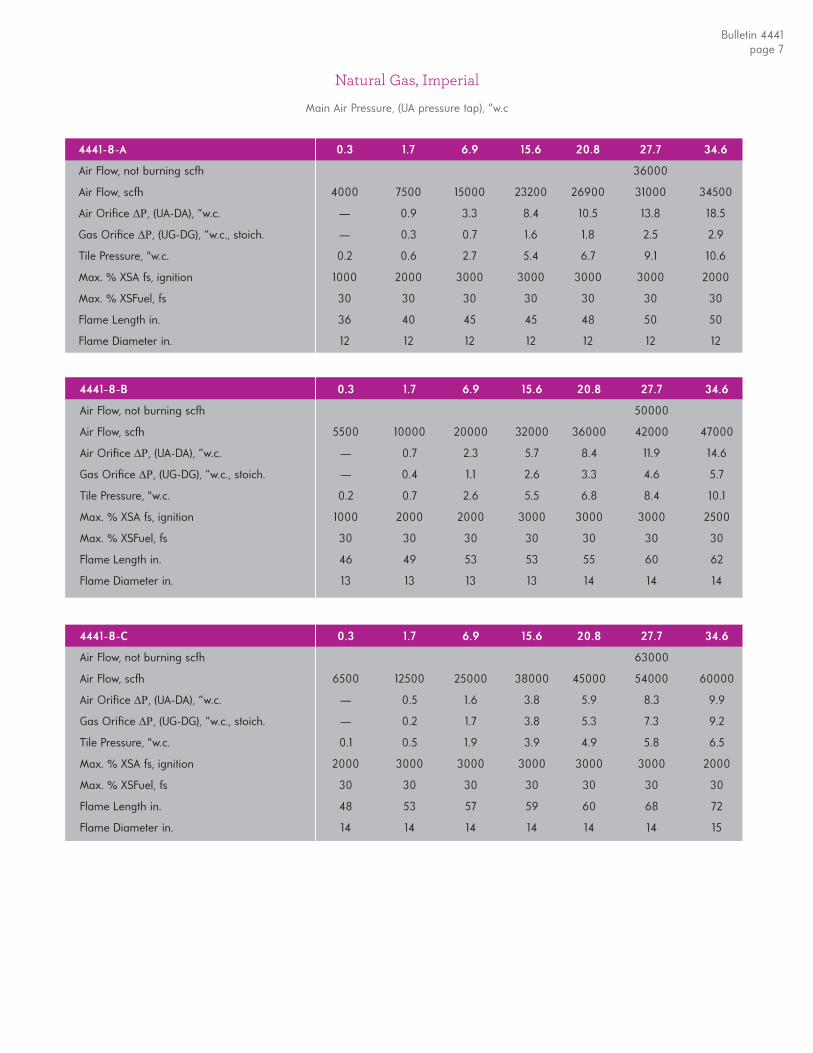
Natural Gas, Imperial
Main Air Pressure, (UA pressure tap), "w.c
Bulletin 4441page 7
4441-8-B 0.3 1.7 6.9 15.6 20.8 27.7 34.6
Air Flow, not burning scfh 50000
Air Flow, scfh 5500 10000 20000 32000 36000 42000 47000
Air Orifi ce , (UA-DA), “w.c. — 0.7 2.3 5.7 8.4 11.9 14.6
Gas Orifi ce , (UG-DG), “w.c., stoich. — 0.4 1.1 2.6 3.3 4.6 5.7
Tile Pressure, "w.c. 0.2 0.7 2.6 5.5 6.8 8.4 10.1
Max. % XSA fs, ignition 1000 2000 2000 3000 3000 3000 2500
Max. % XSFuel, fs 30 30 30 30 30 30 30
Flame Length in. 46 49 53 53 55 60 62
Flame Diameter in. 13 13 13 13 14 14 14
4441-8-C 0.3 1.7 6.9 15.6 20.8 27.7 34.6
Air Flow, not burning scfh 63000
Air Flow, scfh 6500 12500 25000 38000 45000 54000 60000
Air Orifi ce , (UA-DA), “w.c. — 0.5 1.6 3.8 5.9 8.3 9.9
Gas Orifi ce , (UG-DG), “w.c., stoich. — 0.2 1.7 3.8 5.3 7.3 9.2
Tile Pressure, "w.c. 0.1 0.5 1.9 3.9 4.9 5.8 6.5
Max. % XSA fs, ignition 2000 3000 3000 3000 3000 3000 2000
Max. % XSFuel, fs 30 30 30 30 30 30 30
Flame Length in. 48 53 57 59 60 68 72
Flame Diameter in. 14 14 14 14 14 14 15
4441-8-A 0.3 1.7 6.9 15.6 20.8 27.7 34.6
Air Flow, not burning scfh 36000
Air Flow, scfh 4000 7500 15000 23200 26900 31000 34500
Air Orifi ce , (UA-DA), “w.c. — 0.9 3.3 8.4 10.5 13.8 18.5
Gas Orifi ce , (UG-DG), “w.c., stoich. — 0.3 0.7 1.6 1.8 2.5 2.9
Tile Pressure, "w.c. 0.2 0.6 2.7 5.4 6.7 9.1 10.6
Max. % XSA fs, ignition 1000 2000 3000 3000 3000 3000 2000
Max. % XSFuel, fs 30 30 30 30 30 30 30
Flame Length in. 36 40 45 45 48 50 50
Flame Diameter in. 12 12 12 12 12 12 12
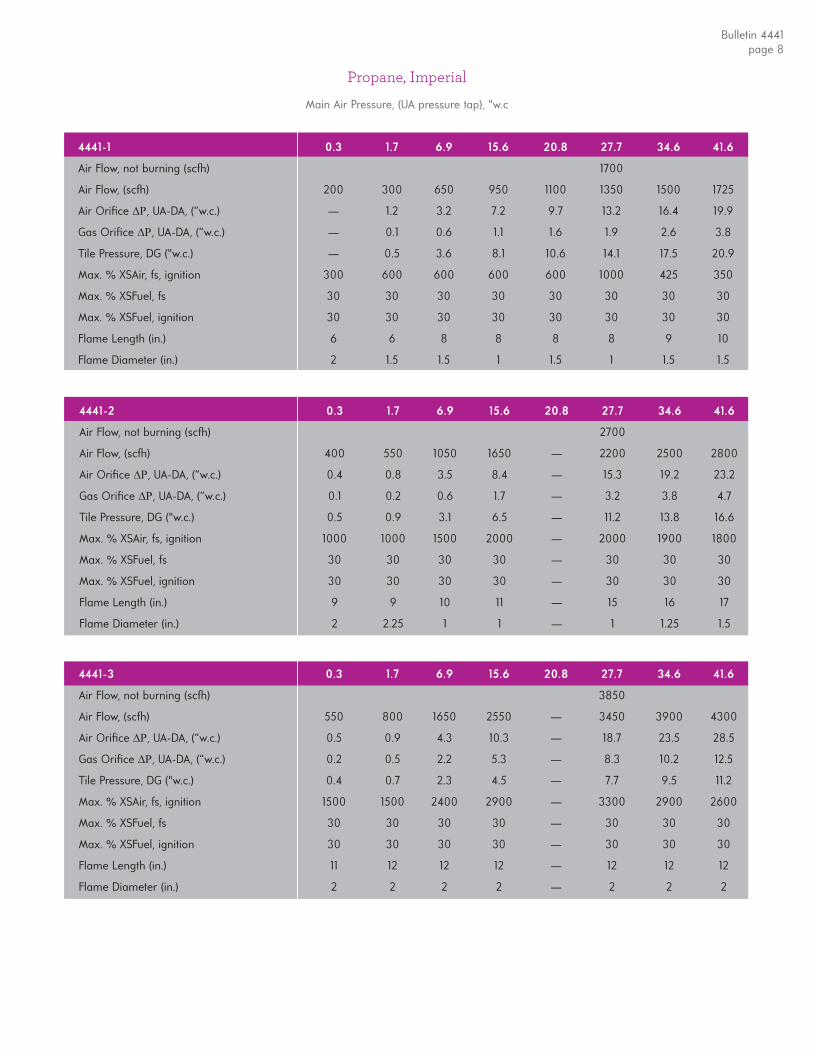
Propane, Imperial
Main Air Pressure, (UA pressure tap), "w.c
Bulletin 4441page 8
4441-3 0.3 1.7 6.9 15.6 20.8 27.7 34.6 41.6
Air Flow, not burning (scfh) 3850
Air Flow, (scfh) 550 800 1650 2550 — 3450 3900 4300
Air Orifi ce , UA-DA, (“w.c.) 0.5 0.9 4.3 10.3 — 18.7 23.5 28.5
Gas Orifi ce , UA-DA, (“w.c.) 0.2 0.5 2.2 5.3 — 8.3 10.2 12.5
Tile Pressure, DG ("w.c.) 0.4 0.7 2.3 4.5 — 7.7 9.5 11.2
Max. % XSAir, fs, ignition 1500 1500 2400 2900 — 3300 2900 2600
Max. % XSFuel, fs 30 30 30 30 — 30 30 30
Max. % XSFuel, ignition 30 30 30 30 — 30 30 30
Flame Length (in.) 11 12 12 12 — 12 12 12
Flame Diameter (in.) 2 2 2 2 — 2 2 2
4441-2 0.3 1.7 6.9 15.6 20.8 27.7 34.6 41.6
Air Flow, not burning (scfh) 2700
Air Flow, (scfh) 400 550 1050 1650 — 2200 2500 2800
Air Orifi ce , UA-DA, (“w.c.) 0.4 0.8 3.5 8.4 — 15.3 19.2 23.2
Gas Orifi ce , UA-DA, (“w.c.) 0.1 0.2 0.6 1.7 — 3.2 3.8 4.7
Tile Pressure, DG ("w.c.) 0.5 0.9 3.1 6.5 — 11.2 13.8 16.6
Max. % XSAir, fs, ignition 1000 1000 1500 2000 — 2000 1900 1800
Max. % XSFuel, fs 30 30 30 30 — 30 30 30
Max. % XSFuel, ignition 30 30 30 30 — 30 30 30
Flame Length (in.) 9 9 10 11 — 15 16 17
Flame Diameter (in.) 2 2.25 1 1 — 1 1.25 1.5
4441-1 0.3 1.7 6.9 15.6 20.8 27.7 34.6 41.6
Air Flow, not burning (scfh) 1700
Air Flow, (scfh) 200 300 650 950 1100 1350 1500 1725
Air Orifi ce , UA-DA, (“w.c.) — 1.2 3.2 7.2 9.7 13.2 16.4 19.9
Gas Orifi ce , UA-DA, (“w.c.) — 0.1 0.6 1.1 1.6 1.9 2.6 3.8
Tile Pressure, DG ("w.c.) — 0.5 3.6 8.1 10.6 14.1 17.5 20.9
Max. % XSAir, fs, ignition 300 600 600 600 600 1000 425 350
Max. % XSFuel, fs 30 30 30 30 30 30 30 30
Max. % XSFuel, ignition 30 30 30 30 30 30 30 30
Flame Length (in.) 6 6 8 8 8 8 9 10
Flame Diameter (in.) 2 1.5 1.5 1 1.5 1 1.5 1.5

Propane, ImperialMain Air Pressure, (UA pressure tap), "w.c
Bulletin 4441page 9
4441-4-B 0.3 1.7 6.9 15.6 20.8 27.7 34.6 41.6
Air Flow, not burning (scfh) 8600
Air Flow, (scfh) 1350 1900 3800 5700 — 7600 — 9200
Air Orifi ce , UA-DA, (“w.c.) 0.5 1.0 3.9 8.9 — 15.9 — 24.6
Gas Orifi ce , UA-DA, (“w.c.) 0.3 0.3 1.3 2.0 — 4.5 — 8.8
Tile Pressure, DG ("w.c.) 0.2 0.4 1.9 4.3 — 7.6 — 10.5
Max. % XSAir, fs, ignition 3000 3000 3200 3300 — 2800 — 1700
Max. % XSFuel, fs 30 30 30 30 — 30 — 30
Max. % XSFuel, ignition 30 30 30 30 — 30 — 30
Flame Length (in.) 16 18 18 20 — 24 — 26
Flame Diameter (in.) 3 3 4 4 — 6 — 6
4441-4-A 0.3 1.7 6.9 15.6 20.8 27.7 34.6 41.6
Air Flow, not burning (scfh) 6200
Air Flow, (scfh) 950 1350 2850 4000 — 5350 — 6800
Air Orifi ce , UA-DA, (“w.c.) 0.5 1.0 3.9 9.2 — 16.5 — 24.6
Gas Orifi ce , UA-DA, (“w.c.) 0.3 0.4 1.0 1.8 — 3.2 — 4.8
Tile Pressure, DG ("w.c.) 0.3 0.5 2.2 4.8 — 8.3 — 12.5
Max. % XSAir, fs, ignition 1100 1300 1500 1750 — 1750 — 900
Max. % XSFuel, fs 30 30 30 30 — 30 — 30
Max. % XSFuel, ignition 30 30 30 30 — 30 — 30
Flame Length (in.) 16 18 22 24 — 24 — 24
Flame Diameter (in.) 2 3 3 4 — 4 — 4
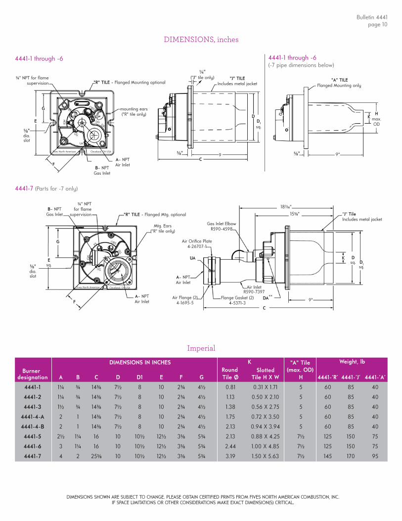
DIMENSIONS, inches
4441-1 through -6
A– NPTAir Inlet
C
K
9"
187⁄16"
4441-7 (Parts for -7 only)
A– NPTAir Inlet
Mtg. Ears("R" tile only)
Esq.
Fives North American Cleveland, OH USA
FS
IGN
OBS
UG
"R" TILE - Flanged Mtg. optional
F
G
4441-1 through -6(-7 pipe dimensions below)
153⁄8"
5⁄8" dia.slot
5⁄8" dia.slot
Air Flange (2)4-1695-5
Dsq. D1
sq.
"J" TileIncludes metal jacket
Flange Gasket (2)4-5371-3
Air InletR590-7397
Gas Inlet ElbowR590-4598
Air Orifi ce Plate4-26707-1
9"5⁄8"
K
Flanged Mounting only"A" TILE
DA**
UA
B– NPTGas Inlet
DG
37-0008-CI
37-0004
Fives North American Cleveland, OH USA
¾ " NPT for fl ame supervision
¾ " NPT for fl ame
supervision
"R" TILE - Flanged Mounting optional
mounting ears("R" tile only)
G
FB– NPTGas Inlet
A– NPTAir Inlet
FS
DGDA
IGN
OBS
UG
UA
¼ "("J" tile only)
5⁄8" 9C
"J" TILE Includes metal jacket
D Hmax. OD
D1
sq.E
Bulletin 4441page 10
DIMENSIONS SHOWN ARE SUBJECT TO CHANGE. PLEASE OBTAIN CERTIFIED PRINTS FROM FIVES NORTH AMERICAN COMBUSTION, INC.IF SPACE LIMITATIONS OR OTHER CONSIDERATIONS MAKE EXACT DIMENSION(S) CRITICAL.
designation A B C D D1 E F G Tile Ø Tile H X W H 4441-'R' 4441-'J' 4441-'A'
4441-1 1¼ ¾ 143⁄8 7½ 8 10 2¾ 4½ 0.81 0.31 X 1.71 5 60 85 40
4441-2 1¼ ¾ 143⁄8 7½ 8 10 2¾ 4½ 1.13 0.50 X 2.10 5 60 85 40
4441-3 1½ ¾ 143⁄8 7½ 8 10 2¾ 4½ 1.38 0.56 X 2.75 5 60 85 40
4441-4-A 2 1 143⁄8 7½ 8 10 2¾ 4½ 1.75 0.72 X 3.50 5 60 85 40
4441-4-B 2 1 143⁄8 7½ 8 10 2¾ 4½ 2.13 0.94 X 3.94 5 60 85 40
4441-5 2½ 1¼ 16 10 10½ 12½ 35⁄8 5¾ 2.13 0.88 X 4.25 7½ 125 150 75
4441-6 3 1¼ 16 10 10½ 12½ 35⁄8 5¾ 2.44 1.00 X 4.85 7½ 125 150 75
4441-7 4 2 255⁄8 10 10½ 12½ 35⁄8 5¾ 3.19 1.50 X 5.63 7½ 145 170 95
Burner Round SlottedWeight, lbK "A" Tile
(max. OD)DIMENSIONS IN INCHES
Imperial
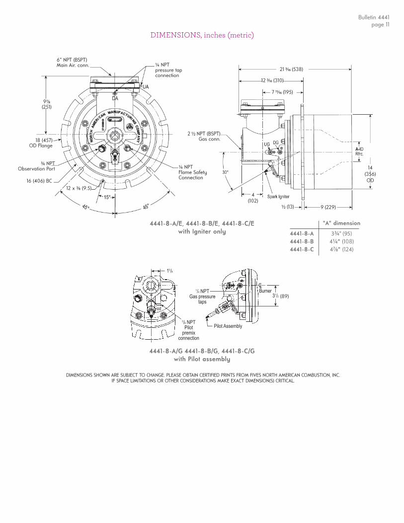
DIMENSIONS, inches (metric)
4441-8-A/E, 4441-8-B/E, 4441-8-C/Ewith Igniter only
4441-8-A/G 4441-8-B/G, 4441-8-C/Gwith Pilot assembly
"A" dimension
4441-8-A 3¾ " (95)4441-8-B 4¼ " (108)4441-8-C 47⁄8" (124)
���������� ����
���������
����
�����������
����������� �������
�� �����
� !�����
DIMENSIONS SHOWN ARE SUBJECT TO CHANGE. PLEASE OBTAIN CERTIFIED PRINTS FROM FIVES NORTH AMERICAN COMBUSTION, INC.IF SPACE LIMITATIONS OR OTHER CONSIDERATIONS MAKE EXACT DIMENSION(S) CRITICAL.
6” NPT (BSPT)Main Air. conn.
97⁄8(251)
18 (457) OD Flange
¾ NPT Observation Port
16 (406) BC12 x 3⁄8 (9.5)
¼ NPTpressure tapconnection
¼ NPTFlame SafetyConnection
(89)
21 3⁄16 (538)
½ (13)
12 3⁄16 (310)
2 ½ NPT (BSPT)Gas conn.
4(102)
7 11⁄16 (195)
9 (229)
14 (356)OD
Bulletin 4441page 11
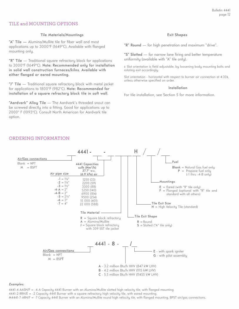
4441 - -
Tile Material
R = Square block refractoryA = Alumina/MulliteJ = Square block refractory with 309 SST tile jacket
Tile Exit Shape
R = Round S = Slotted ("A" tile only)
Tile Exit SizeH = High Velocity Tile (standard)
Mountings
E = Eared (with "R" tile only)F = Flanged (optional with "R" tile and
standard with all others)
Fuel
Blank = Natural Gas fuel only P = Propane fuel only (-1 thru -4-B only)
Examples:
4441-4-AASH/F = -4-A Capacity 4441 Burner with an Alumina/Mullite slotted high velocity tile, with fl anged mounting. 4441-2-RRH/E = -2 Capacity 4441 Burner with a square refractory high velocity tile, with eared mounting.M4441-7-ARH/F = -7 Capacity 4441 Burner with an Alumina/Mullite round high velocity tile, with fl anged mounting, BPST air/gas connections.
ORDERING INFORMATION
‡ Slot orientation is fi eld adjustable, by loosening body mounting bolts and rotating exit accordingly.
H
TILE and MOUNTING OPTIONS
27.7" w.c. (6.9 kPa) air
1250 (33)2200 (59)3300 (88)5250 (140)6900 (184)9500 (254)15 000 (401)22 000 (588)
Air pipe size
-1 = 1¼ " -2 = 1¼ " -3 = 1½ " -4-A = 2" -4-B = 2" -5 = 2½ " -6 = 3" -7 = 4"
4441 Capacitiesscfh (Nm3/h)
Tile Materials/Mountings
“A” Tile — Alumina/Mullite tile for fi ber wall and most applications up to 3000°F (1649°C). Available with fl anged mounting only.
“R” Tile — Traditional square refractory block for applications to 3000°F (1649°C). Note: Recommended only for installation in solid wall construction furnaces/kilns. Available with either fl anged or eared mounting.
“J” Tile — Traditional square refractory block with metal jacket for applications to 1800°F (982°C). Note: Recommended for installation of a square refractory block tile in soft wall.
“Aardvark” Alloy Tile — The Aardvark’s threaded snout can be screwed directly into a fi tting. Good for applications up to 2000° F (1093°C). Consult North American for Aardvark tile option.
Exit Shapes “R” Round — for high penetration and maximum “drive”.
“S” Slotted — for narrow lane fi ring and better temperature uniformity (available with “A” tile only).
Installation
For tile installation, see Section 5 for more information.
Air/Gas connectionsBlank = NPT M = BSPT
Bulletin 4441page 12
4441 - 8 - /E - with spark igniterG - with pilot assembly
A - 3.2 million Btu/h HHV (847 kW LHV)B - 4.2 million Btu/h HHV (1115 kW LHV)C - 5.5 million Btu/h HHV (11455 kW LHV)
Air/Gas connectionsBlank = NPT M = BSPT
Slot orientation - horizontal with respect to burner air connection at 4:30‡, unless otherwise specifi ed on order.
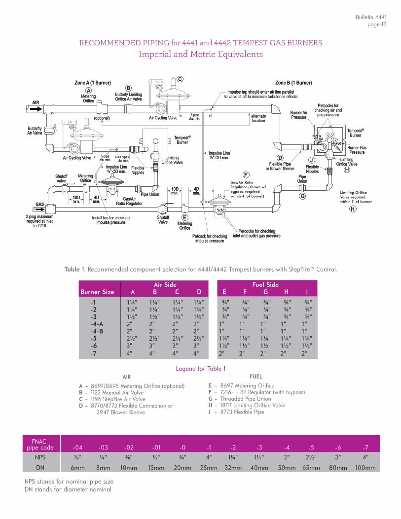
RECOMMENDED PIPING for 4441 and 4442 TEMPEST GAS BURNERS
Table 1. Recommended component selection for 4441/4442 Tempest burners with StepFireTM Control.
AIR A – 8697/8695 Metering Orifi ce (optional)B – 1122 Manual Air ValveC – 1196 StepFire Air ValveD – 8770/8773 Flexible Connection or 2947 Blower Sleeve
Legend for Table 1 FUEL
E – 8697 Metering Orifi ceF – 7216- - BP Regulator (with bypass)G – Threaded Pipe UnionH – 1807 Limiting Orifi ce ValveJ – 8773 Flexible Pipe
Air Side Fuel Side Burner Size A B C D E F G H I
-1 1¼" 1¼" 1¼" 1¼" ¾" ¾" ¾" ¾" ¾" -2 1¼" 1¼" 1¼" 1¼" ¾" ¾" ¾" ¾" ¾" -3 1½" 1½" 1½" 1½" ¾" ¾" ¾" ¾" ¾" -4-A 2" 2" 2" 2" 1" 1" 1" 1" 1" -4-B 2" 2" 2" 2" 1" 1" 1" 1" 1" -5 2½" 2½" 2½" 2½" 1¼" 1¼" 1¼" 1¼" 1¼" -6 3" 3" 3" 3" 1½" 1½" 1½" 1½" 1½" -7 4" 4" 4" 4" 2" 2" 2" 2" 2"
Limiting Orifi ceValve required within 1' of burner
H
Gas/Air Ratio Regulator (shown w/ bypass, required within 4' of burner)
Imperial and Metric Equivalents
Bulletin 4441page 13
pipe code -04 -03 -02 -01 -0 -1 -2 -3 -4 -5 -6 -7
NPS 1⁄8" ¼ " 3⁄8" ½ " ¾ " 4" 1¼ " 1½ " 2" 2½ " 3" 4"
DN 6mm 8mm 10mm 15mm 20mm 25mm 32mm 40mm 50mm 65mm 80mm 100mm
FNAC
NPS stands for nominal pipe sizeDN stands for diameter nominal
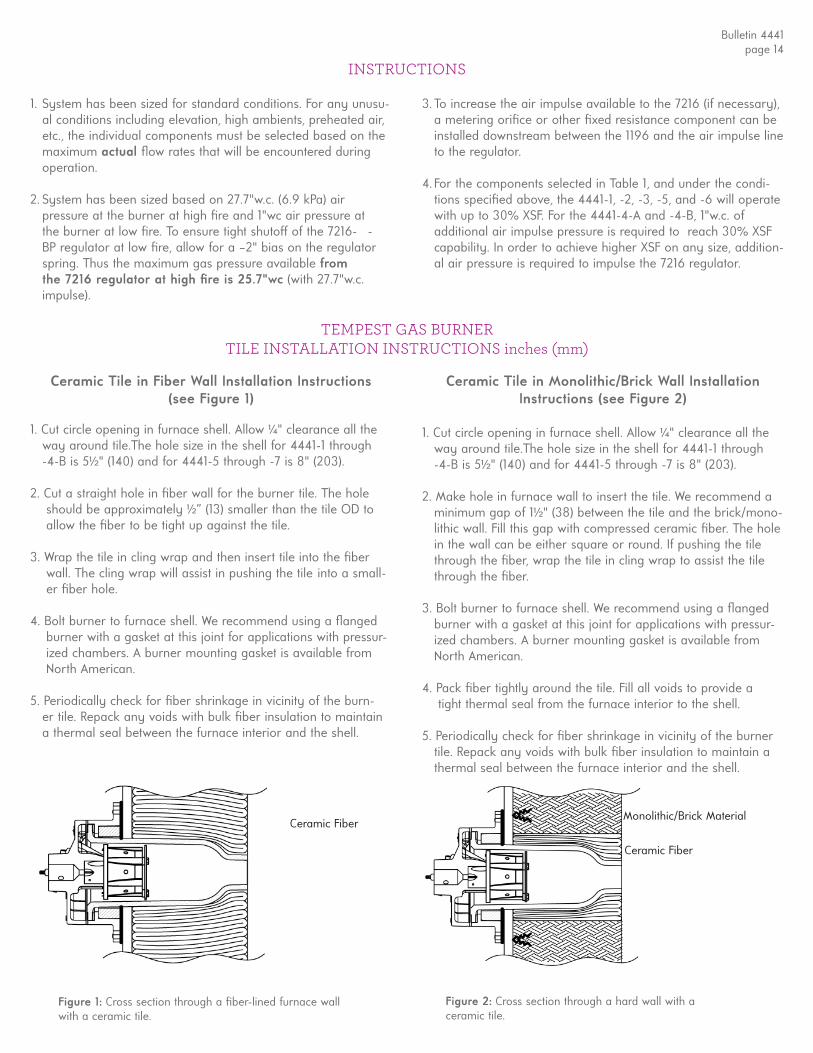
TEMPEST GAS BURNERTILE INSTALLATION INSTRUCTIONS inches (mm)
Ceramic Tile in Fiber Wall Installation Instructions(see Figure 1)
1. Cut circle opening in furnace shell. Allow ¼ " clearance all the way around tile.The hole size in the shell for 4441-1 through -4-B is 5½ " (140) and for 4441-5 through -7 is 8" (203).
2. Cut a straight hole in fi ber wall for the burner tile. The hole should be approximately ½ ” (13) smaller than the tile OD to allow the fi ber to be tight up against the tile.
3. Wrap the tile in cling wrap and then insert tile into the fi ber wall. The cling wrap will assist in pushing the tile into a small- er fi ber hole.
4. Bolt burner to furnace shell. We recommend using a fl anged burner with a gasket at this joint for applications with pressur- ized chambers. A burner mounting gasket is available from North American. 5. Periodically check for fi ber shrinkage in vicinity of the burn- er tile. Repack any voids with bulk fi ber insulation to maintain a thermal seal between the furnace interior and the shell.
Ceramic Tile in Monolithic/Brick Wall Installation Instructions (see Figure 2)
1. Cut circle opening in furnace shell. Allow ¼ " clearance all the way around tile.The hole size in the shell for 4441-1 through -4-B is 5½ " (140) and for 4441-5 through -7 is 8" (203).
2. Make hole in furnace wall to insert the tile. We recommend a minimum gap of 1½ " (38) between the tile and the brick/mono- lithic wall. Fill this gap with compressed ceramic fi ber. The hole in the wall can be either square or round. If pushing the tile through the fi ber, wrap the tile in cling wrap to assist the tile through the fi ber.
3. Bolt burner to furnace shell. We recommend using a fl anged burner with a gasket at this joint for applications with pressur- ized chambers. A burner mounting gasket is available from North American.
4. Pack fi ber tightly around the tile. Fill all voids to provide a tight thermal seal from the furnace interior to the shell.
5. Periodically check for fi ber shrinkage in vicinity of the burner tile. Repack any voids with bulk fi ber insulation to maintain a thermal seal between the furnace interior and the shell.
Figure 1: Cross section through a fi ber-lined furnace wall with a ceramic tile.
Figure 2: Cross section through a hard wall with a ceramic tile.
Ceramic Fiber
Ceramic Fiber
Monolithic/Brick Material
Bulletin 4441page 14
1. System has been sized for standard conditions. For any unusu-al conditions including elevation, high ambients, preheated air, etc., the individual components must be selected based on the maximum actual fl ow rates that will be encountered during operation.
2. System has been sized based on 27.7"w.c. (6.9 kPa) air pressure at the burner at high fi re and 1"wc air pressure at the burner at low fi re. To ensure tight shutoff of the 7216- - BP regulator at low fi re, allow for a –2" bias on the regulator spring. Thus the maximum gas pressure available from the 7216 regulator at high fi re is 25.7"wc (with 27.7"w.c. impulse).
3. To increase the air impulse available to the 7216 (if necessary), a metering orifi ce or other fi xed resistance component can be installed downstream between the 1196 and the air impulse line to the regulator.
4. For the components selected in Table 1, and under the condi-tions specifi ed above, the 4441-1, -2, -3, -5, and -6 will operate with up to 30% XSF. For the 4441-4-A and -4-B, 1"w.c. ofadditional air impulse pressure is required to reach 30% XSF capability. In order to achieve higher XSF on any size, addition-al air pressure is required to impulse the 7216 regulator.
INSTRUCTIONS
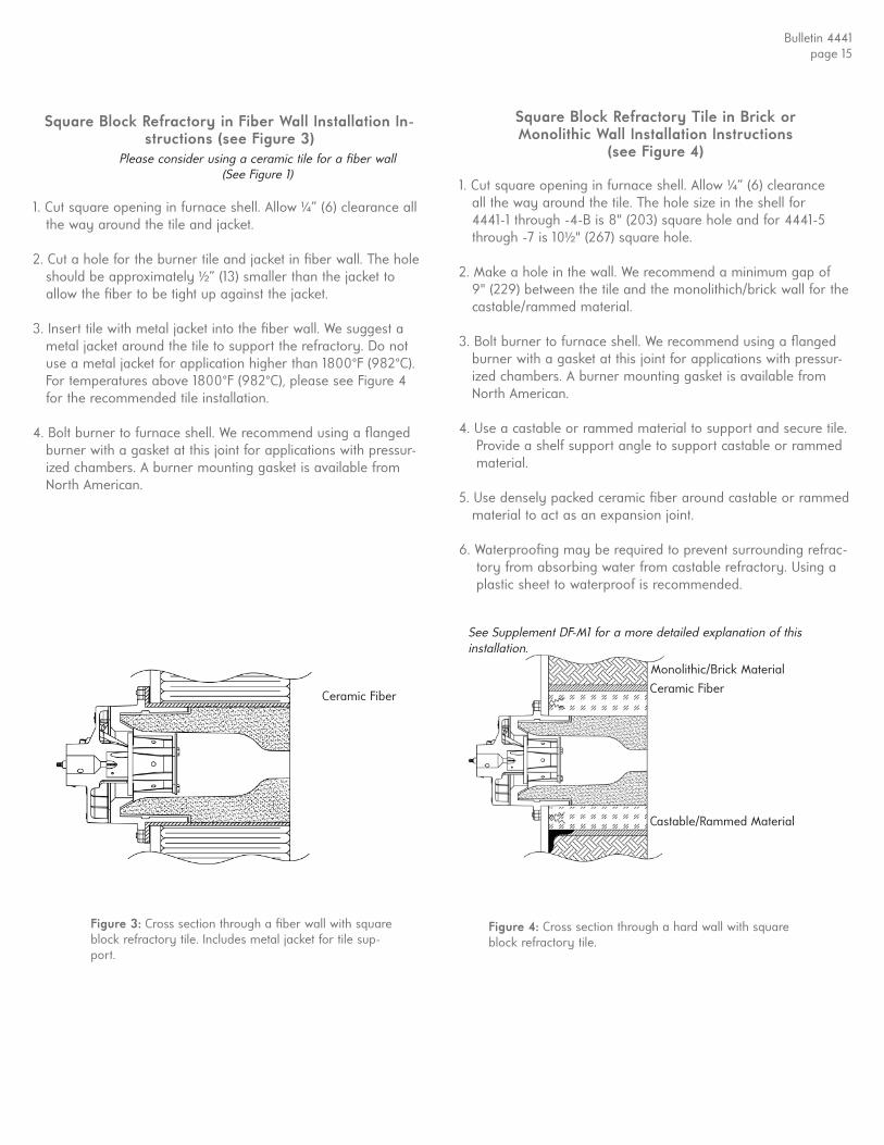
Square Block Refractory in Fiber Wall Installation In-structions (see Figure 3)
1. Cut square opening in furnace shell. Allow ¼” (6) clearance all the way around the tile and jacket. 2. Cut a hole for the burner tile and jacket in fi ber wall. The hole should be approximately ½ ” (13) smaller than the jacket to allow the fi ber to be tight up against the jacket.
3. Insert tile with metal jacket into the fi ber wall. We suggest a metal jacket around the tile to support the refractory. Do not use a metal jacket for application higher than 1800°F (982°C). For temperatures above 1800°F (982°C), please see Figure 4 for the recommended tile installation.
4. Bolt burner to furnace shell. We recommend using a fl anged burner with a gasket at this joint for applications with pressur- ized chambers. A burner mounting gasket is available from North American.
Square Block Refractory Tile in Brick or Monolithic Wall Installation Instructions
(see Figure 4)
1. Cut square opening in furnace shell. Allow ¼” (6) clearance all the way around the tile. The hole size in the shell for 4441-1 through -4-B is 8" (203) square hole and for 4441-5 through -7 is 10½ " (267) square hole. 2. Make a hole in the wall. We recommend a minimum gap of 9" (229) between the tile and the monolithich/brick wall for the castable/rammed material.
3. Bolt burner to furnace shell. We recommend using a fl anged burner with a gasket at this joint for applications with pressur- ized chambers. A burner mounting gasket is available from North American.
4. Use a castable or rammed material to support and secure tile. Provide a shelf support angle to support castable or rammed material.
5. Use densely packed ceramic fi ber around castable or rammed material to act as an expansion joint.
6. Waterproofi ng may be required to prevent surrounding refrac- tory from absorbing water from castable refractory. Using a plastic sheet to waterproof is recommended.
Ceramic Fiber
Monolithic/Brick MaterialCeramic Fiber
Castable/Rammed Material
Figure 3: Cross section through a fi ber wall with square block refractory tile. Includes metal jacket for tile sup-port.
Figure 4: Cross section through a hard wall with square block refractory tile.
Please consider using a ceramic tile for a fi ber wall (See Figure 1)
See Supplement DF-M1 for a more detailed explanation of this installation.
Bulletin 4441page 15

INSTRUCTIONS for ASSEMBLY and INSTALLATIONof BURNER AIR and GAS PETCOCKS
Tools required: 6" adjustable wrench and pliers.
Table 1. List of Parts
Item No. Description Quantity
1 1⁄8" Petcock 4 2 1⁄8" Hose Nipple 4 3 1⁄8" × 1½ " Nipple 2 4 1⁄8" Coupling 2
Figure 2. Petcock Assemblies
INSTRUCTIONS
1) Determine burner size stamped on the nameplate which is mounted on the front of the burner body. Find corresponding number for the petcock assemblies in Table 3.
2) Assemble petcocks as detailed in Figure 2 illustrations A & B. Refer to Table 1 for item description.
3) Remove pipe plugs from the burner body. Plug locations (UA, DA, UG, and DG) are cast on the burner body.
4) Replace pipe plugs with the proper petcock assembly. Tighten to ensure there is no leakage.
5) Check for leakage during burner operation.
NOTE: We recommend using liquid Tefl on sealer on pipe threads.
Table 3. Use of Petcock Assemblies
Taps
Burner UG DG UA DA
4442-0 through -4 B A B A
4442-5 through -7 B B A A
4441-1 through -7 A A A A
4441-8 A B A A Note: UG, DG, UA, DA are appropriately labeled on the burner body.
A
ITEM 1
ITEM 1ITEM 3
ITEM 2
ITEM 2ITEM 4
B
CAUTION: Valves must be kept in closed position when notin use.
Bulletin 4441page 16
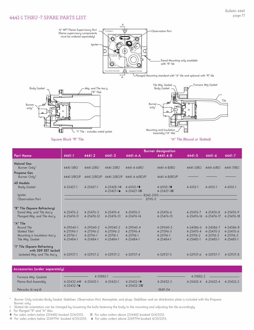
Body Gasket
Burneronly*
Mtg. and Tile Ass'y("R" Tile)
"J" Tile - includes metal jacket
Tile Mtg. Gasket Furnace Mtg GasketBody Gasket
TileBurneronly*
Mounting and Insulation Assembly ("A" tile)
Square Block "R" Tile "A" Tile (Round or Slotted)
Igniter
A
A
Observation Port
Fives North American Cleveland, OH USA
FS
DG
DA
IGN
OBS
UG
UA
¾ " NPT Flame Supervisory Port(fl ame supervisory components
must be ordered separately)
Flanged Mounting standard with "A" tile and optional with "R" tile
Eared Mounting only availablewith "R" tile
4441-1 THRU -7 SPARE PARTS LIST
37-0006/CI
37-0289/HR
Part Name 4441-1 4441-2 4441-3 4441-4-A 4441-4-B 4441-5 4441-6 4441-7
Natural Gas Burner Only* 4441-1/BO 4441-2/BO 4441-3/BO 4441-4-A/BO 4441-4-B/BO 4441-5/BO 4441-6/BO 4441-7/BO
Propane Gas Burner Only* 4441-1/BO/P 4441-2/BO/P 4441-3/BO/P 4441-4-A/BO/P 4441-4-B/BO/P
All Models Body Gasket 4-25427-1 4-25427-1 4-25428-1 4-6050-1 4-6050-1 4-6102-1 4-6102-1 4-6102-1 4-25427-1 4-25427-1 4-25427-1 Igniter Observation Port
"R" Tile (Square Refractory) Eared Mtg. and Tile Ass'y 4-25476-2 4-25476-3 4-25476-4 4-25476-5 4-25476-6 4-25476-7 4-25476-8 4-25476-9 Flanged Mtg. and Tile Ass'y 4-25476-11 4-25476-12 4-25476-13 4-25476-14 4-25476-15 4-25476-16 4-25476-17 4-25476-18
"A" Tile Round Tile 4-29040-1 4-29040-2 4-29040-3 4-29040-4 4-29040-5 4-24586-6 4-24586-7 4-24586-8 Slotted Tile† 4-27596-1 4-27596-2 4-27596-3 4-27596-4 4-27596-5 4-25470-4 4-25470-5 4-25470-6 Mounting & Insulation Ass'y 4-25716-1 4-25716-1 4-25716-1 4-25716-1 4-25716-1 4-25716-2 4-25716-2 4-25716-2 Tile Mtg. Gasket 4-25484-1 4-25484-1 4-25484-1 4-25484-1 4-25484-1 4-25485-1 4-25485-1 4-25485-1
"J" Tile (Square Refractory with 309 SST Jacket) Jacketed Mtg. and Tile Ass'y 4-52937-1 4-52937-2 4-52937-3 4-52937-4 4-52937-5 4-52937-6 4-52937-7 4-52937-8
Part Name 4441-1 4441-2 4441-3 4441-4-A 4441-4-B 4441-5 4441-6 4441-7
Furnace Mtg. Gasket‡ Flame Rod Assembly 4-25432-4 4-25432-1 4-25432-1 4-25432-1 4-25432-3 4-25432-4 4-25432-4 4-25432-2 4-25432-7 4-25432-3 Petcocks (4 req'd)
Burner designation
R240-21008790-0
4-51882-1 4-51882-2
* Burner Only includes Body Gasket, Stabilizer, Observation Port, Nameplate, and plugs. Stablilizer and air distribution plate is included with the Propane Burner only.
† Slotted tile orientation can be changed by loosening the bolts fastening the body to the mounting and adjusting the tile accordingly.‡ For fl anged "R" and "A" tiles. For sales orders below 2214482 booked 12/4/2012. For sales orders above 2214482 booked 12/4/2012. For sales orders below 2249794 booked 4/30/2015. For sales orders above 2249794 booked 4/30/2015.
Bulletin 4441page 17
Accessories (order separately)
1849-04

4441-8 SPARE PARTS LIST
Part Name -8-A -8-B -8-C
Air Inlet Flange 4-1695-6 4-1695-6 4-1695-6 Air Inlet Gasket (2 req'd) 4-5371-4 4-5371-4 4-5371-4 Body 4-29217-1 4-29217-1 4-29217-1Combustion Cup Assembly 4-29796-1 4-29796-1 4-29796-1Gas Nozzle 4-29793-1 4-29793-1 4-29793-1Igniter (-E version only) 4-3681-1 4-3681-1 4-3681-1 Inlet Air Orifi ce 4-29795-1 4-29795-2 4-29795-3Mounting & Tile Assembly 4-29219-1 4-29219-2 4-29219-3Mounting Gasket (2 req'd) 4-29221-1 4-29221-1 4-29221-1Nozzle Mounting Plate Assembly 4-29824-1 4-29824-1 4-29824-1Pilot Assembly (-G version only) 4-28157-1 4-28157-1 4-28157-1Pilot/Igniter Yoke 4-27369-1 4-27369-1 4-27369-1
Accessories (order separately)
Flame Rod 4-25432-8 4-25432-8 4-25432-8Petcocks (4 req'd) 1849-04 1849-04 1849-04Furnace Mtg. Gasket
Air FlangeGaskets(2 REQ)
Inlet Air Orifi ce
Air Inlet Flange Mounting Gasket(2 REQ)
Mounting &TileAssembly
Combustion Cup Assembly
Nozzle Mtg. Plate Assembly
Gas Nozzle
Body
Igniter
Pilot/IgniterYoke
Bulletin 4441page 18
WARNING: Situations dangerous to personnel and property may exist with the operation and maintenance of any combustion equipment. The presence of fuels, oxidants, hot and cold combustion products, hot surfaces, electrical power in control and ignition circuits, etc., are inherent with any combustion application. Components in combustion systems may exceed 160°F (71°C) surface temperatures and present hot surface contact hazard. Fives North American Combustion, Inc. suggests the use of combustion systems that are in compliance with all Safety Codes, Standards, Regulations and Directives; and care in operation.
Copy
right
© 2
018
- Fi
ves
- Al
l rig
hts
rese
rved
| Bu
letin
444
1 02
/18
CONTACT US:Fives North American Combustion, Inc. 4455 East 71st Street - Cleveland, OH 44105 - USATel: +1 216 271 6000 - Fax: +1 216 373 4237Email: fna.sales@fi vesgroup.com www.fi vesgroup.com
4-53689-1


![Combustion in compressed ignition engine, pressure data [Autosaved]1.pptx](https://img.pdfslide.net/doc/110x75/577cc1e41a28aba71193fb08/combustion-in-compressed-ignition-engine-pressure-data-autosaved1pptx.jpg)