Embed Size (px)
Citation preview

Paper WM-T4-02-1
WM-T4-02
HAMMER-PIPE ENERGY TRANSFER EFFICIENCY FOR PIPE RAMMING
Tadesse Meskele1 and Armin W. Stuedlein2, Ph.D., P.E.
1 Graduate Research Assistant, Oregon State University 2 Assistant Professor and Loosley Faculty Fellow, Oregon State University
ABSTRACT: The amount of energy transfer from the hammer to the casing is a critical consideration for assessing
of the constructability of the required length and diameter of pipe with a given hammer. Due to various contractor-selected pipe-hammer connections and natural sources of energy loss (e.g., thermal, frictional, etc.), the energy
transfer efficiency of pipe ramming hammers must be less than 100 percent; however, actual hammer- pipe energy
transfer efficiencies, defined as the ratio of actual energy transferred to the rated hammer energy, have not been
reported to-date. Overestimates of hammer- pipe energy transfer could result in corresponding overestimates of
driving stresses and penetration rates; likewise, over-estimates of driving stress could lead to excessive and
uneconomical wall thickness. This study focuses on the characterization of hammer- pipe energy transfer
efficiencies for commonly used pneumatic and hydraulic hammers observed during production and test pipe
ramming installations. The observed energy transfer was found to depend on the type of hammer, the hammer-pipe
connection (e.g., collets vs. ram cones), the hammer alignment, and the degree of tension on restraining chains.
Observations of energy transfer indicate that hammer efficiency can vary widely; average observed efficiencies
ranged from 20 to 50 percent. Additionally, a parametric study on pipe drivability is presented, and confirmed the importance of energy transfer on the rate of pipe penetration. The characterization of pipe-hammer energy transfer
provided herein can form the basis for a rational evaluation of pipe drivability for a given hammer and pipe
geometry, and can help owners, engineers, consultants, and contractors determine the likelihood of a successful
casing installation.
1. INTRODUCTION
Pipe ramming is increasingly becoming a popular cost-effective trenchless solution for the installation of new
culverts and pipes since it mitigates many of the logistical issues associated with conventional open-cut placement
(Stuedlein and Meskele 2012). The traditional open-cut technique involves excavation of a trench across the road,
placing the culvert and restoration of the road surface which have adverse impact on the daily life of road users
through road or rail closures, traffic interruptions and detours, noise pollution, and restricted or blocked entrances to homes and businesses (Ariaratnam et al. 2006). Pipe ramming is regarded as an efficient trenchless technique that
allows installation of casings in soils with large cobbles and boulders, ground conditions that may pose greater
difficulty to other trenchless technologies. Thus many DOTs and agencies are adopting pipe ramming and
employing the method for pipe and culvert installation projects.
Pipe ramming involves the hammering of a pipe casing into the ground with high frequency percussive blows
generated by a pneumatically or hydraulically powered encased piston rammer (Stuedlein and Meskele 2012). The
piston strikes the inside of the heavy steel shell which is connected to the pipe to be installed; upon impact, the
energy generated from the piston strike is transferred to the pipe and enables penetration of the hammer-pipe system
into the ground. Because the transfer of energy from the hammer to the pipe is imperfect, characterizing the actual
energy propelling the pipe is a critical step in the evaluation of the drivability and rate of penetration of the pipe.
North American Society for Trenchless Technology (NASTT)
NASTT’s 2013 No-Dig Show
Sacramento, California
March 3-7, 2013
Paper WM-T4-02-2
Hence, characterization of hammer-pipe efficiency is an important element for the successful and safe installation of
a pipe. This study addresses the energy transfer efficiency of commonly used pneumatic and hydraulic pipe
ramming hammers and their connection to the pipe to quantify the actual energy delivered and the factors
controlling the delivery of energy. The work presented herein forms a critical component in the selection of an
appropriately sized hammer, pipe wall thickness, and feasibility of installation of a given length of pipe.
2. WAVE PROPAGATION ANALYSIS
The planning of pipe ramming installations requires an assessment of the constructability of the required length and
diameter of pipe with a given hammer and evaluation of the likelihood of damage to the pipe due to excessive
driving stresses. Wave propagation analysis with the one-dimensional wave equation, typically used for pile
foundations and largely attributed to Smith (1960), can be employed to assess the drivability of the proposed
hammer and pipe geometry. Smith (1960) proposed the solution of wave propagation in an elastic pile using a finite
difference scheme by idealizing the actual continuous pile as a series of discretized lumped masses connected by
massless linear springs and dampers representing soil resistance on each mass. The soil resistance mobilized in
response to a hammer impact comprises a static component, represented by the linear-elastic springs, and a dynamic
component of resistance represented by the dashpot (damper). The static resistance model is driven by an elasto-
plastic constitutive law where the soil is assumed to compress elastically for a specified relative soil-pipe movement, defined as the quake (Q) and fails plastically with constant resistance for greater relative soil-pipe movements. The
dynamic soil resistance component is an instantaneous resistance offered by the ground due to the rapid motion of
the pipe. The dynamic resistance model assumes that the amount of viscous damping is proportional to the pipe
velocity and static soil resistance with the constant of proportionality defined as the damping constant (J).
Over the last half century, various researchers (Samson et al. 1963, Rausche et al. 1972, Goble and Rausche 1976,
Randolph and Simons 1986, Lee et al. 1988) have examined Smith’s 1-D approach and contributed improvements
that addressed the limitations in the model. GRLWEAP® (GRL Wave Equation Analysis for Piles), developed by
Goble and Rausche (1976), is one of most widely used wave equation programs. Francis et al. (2012) describe the
use of wave equation analyses for the estimation of the driving stresses for a pipe ramming project. In general, wave
propagation analysis requires the specification of various model inputs, including the pipe properties (diameter, length, wall thickness, modulus, and mass density), soil properties (face and casing static soil resistance, quake, and
damping), and hammer properties (rated energy, energy transfer efficiency). The wave propagation analysis results
in a predicted penetration rate (i.e., blow count) measured in blows per foot or blows per meter as a function of
assumed energy delivered, total static and dynamic soil resistance acting on the pipe (i.e., sum of face and casing
resistance), and driving stresses induced in the pipe. Refer to Stuedlein and Meskele (2013) for details.
The most critical parameter affecting the drivability of a pipe is the amount of energy transferred from the hammer
to the pipe. In order to illustrate the sensitivity of relevant factors affecting the drivability of a pipe ramming
installation, a parametric analysis of pipe drivability with variation in the assumed static soil resistance was
investigated using GRLWEAP®. An open-ended steel pipe 600 mm in diameter, with 12.5 mm wall thickness, and
30 m in length was considered for the parametric analysis. A 400 mm pneumatic HammerHead hammer, with an
estimated maximum energy of 6.4 kN-m and impact rate of 231 blows per minute (bpm) was modeled. The parametric study considered the following baseline parameter values: hammer-pipe energy transfer efficiency, e =
0.3, shaft quake, Qs = 2.5 mm, face quake, Qf = 2.5 mm, shaft damping, Js = 2.6 mm, and face damping, Jf = 2.6
mm. The parametric study was conducted to investigate the sensitivity of each model parameter while holding the
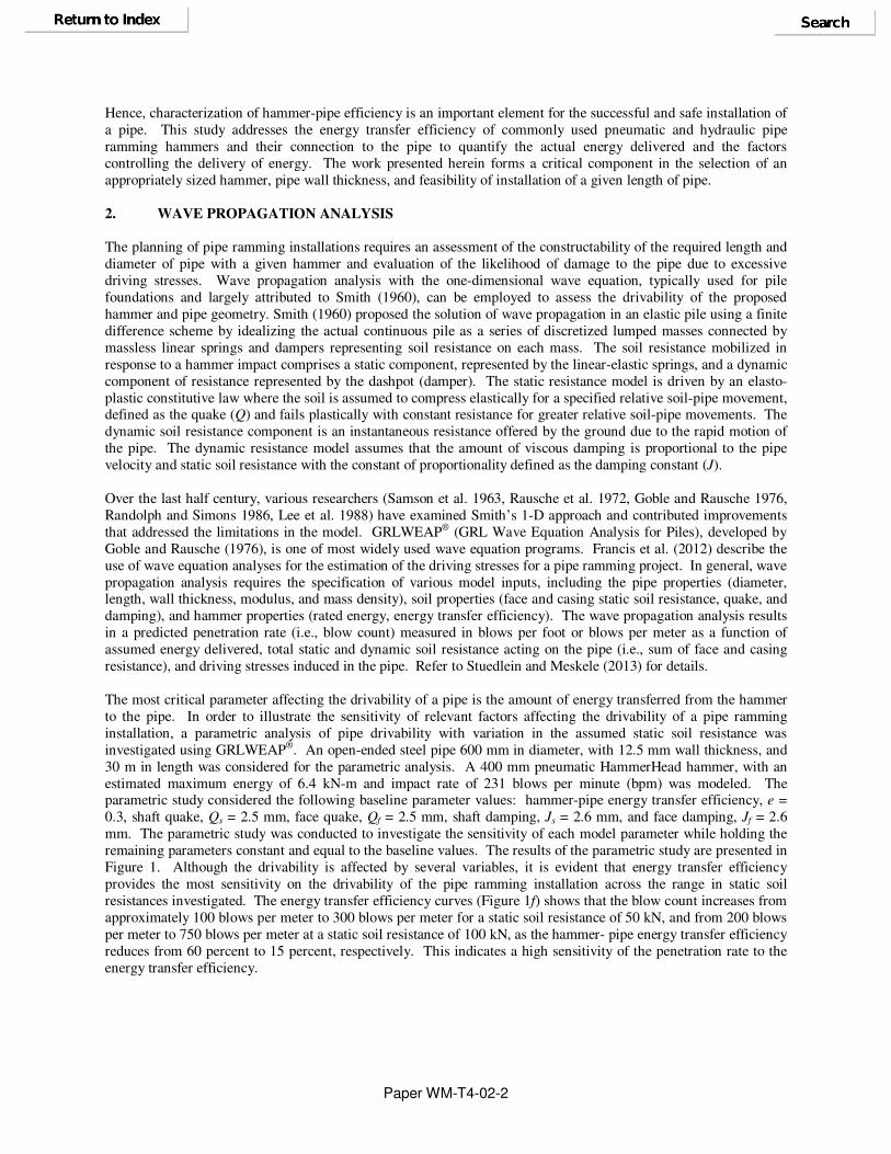
remaining parameters constant and equal to the baseline values. The results of the parametric study are presented in
Figure 1. Although the drivability is affected by several variables, it is evident that energy transfer efficiency
provides the most sensitivity on the drivability of the pipe ramming installation across the range in static soil
resistances investigated. The energy transfer efficiency curves (Figure 1f) shows that the blow count increases from
approximately 100 blows per meter to 300 blows per meter for a static soil resistance of 50 kN, and from 200 blows
per meter to 750 blows per meter at a static soil resistance of 100 kN, as the hammer- pipe energy transfer efficiency
reduces from 60 percent to 15 percent, respectively. This indicates a high sensitivity of the penetration rate to the
energy transfer efficiency.

Paper WM-T4-02-3
Figure 1. Parametric analysis of pipe ramming drivability analysis indicating the variation in blow count in
blows per meter (b/m) as a function of static soil resistance, by varying (a) the percentage of shaft resistance
(b) shaft damping (c) face damping (d) shaft quake (e) face quake, and (f) hammer-pipe energy transfer
efficiency.
3. ANALYSIS OF PIPE RAMMING HAMMER –PIPE ENERGY TRANSFER EFFICIENCY
Selection of the appropriate hammer is critical to the success of a pipe ramming installation. Generally, there are
two types of hammers that are used in pipe ramming installations: pneumatic and hydraulic hammers. Pneumatic
hammers are the most frequently used hammer in the United States, and utilizes compressed air to power a
reciprocating piston within a specially designed steel shell (Schrank et al. 2009, Currey et al. 2009). The piston
strikes the inside walls of the shell which is in turn connected to the pipe via contractor selected collets, pipe cones, and/or ram cones, which facilitate the transfer of energy to pipe. Pneumatic hammers generally require a large
external air compressor to provide the air supply. Hydraulic hammers operate on a similar principle as that of
pneumatic hammers, however, they utilize compressed hydraulic fluid to power the internal piston. The use of the
0
50
100
150
200
0 250 500 750 1000 1250
Sta
tic
So
il R
esis
tan
ce
(k
N)
Blow Count (b/m)
20%
40%
60%
80%
Proportion of Shaft Resistance
(a)
0
50
100
150
200
0 250 500 750 1000 1250
Sta
tic S
oil R
esis
tan
ce (
kN
)
Blow Count (b/m)
12 34
(b)
Shaft Damping Js (s/m)
0
50
100
150
200
0 250 500 750 1000 1250
Sta
tic
So
il R
es
ista
nc
e (
kN
)
Blow Count (b/m)
1234
(c)
Face Damping Jf (s/m)
0
50
100
150
200
0 250 500 750 1000 1250Sta
tic
So
il R
es
ista
nc
e (k
N)
Blow Count (b/m)
0.5
1
2
2.5
(d)
Shaft Quake Qs (mm)
0
50
100
150
200
0 250 500 750 1000 1250
Sta
tic
So
il R
es
ista
nc
e (
kN
)
Blow Count (b/m)
0.5
1
2
2.5
(e)
Face Quake Qf (mm)
0
50
100
150
200
0 250 500 750 1000 1250
Sta
tic
So
il R
es
ista
nc
e (
kN
)
Blow Count (b/m)
15% 30%
45% 60%
(f)
Hammer-Pipe Energy Transfer Efficiency, e

Paper WM-T4-02-4
hydraulic fluid instead of compressed air allows an overall smaller ram and lightweight hydraulic power unit as
compared to the air compressors used by pneumatic systems. In general, the internal hammer efficiency of
hydraulic hammers may be somewhat better as compared to pneumatic hammers, however, they are more expensive
(Yin et al. 2003).
The amount of energy and frequency of impact can be varied during driving by changing the air or fluid pressure supplied to the hammer and the rate at which it flows within the hammer casing. Generally speaking, contractors
elect to operate hammers at medium high to maximal operational levels, with adjustments made to limit the pipe
recoil that develops in response to restitution and elastic rebound of the pipe. The transfer of energy from the
hammer to the pipe depends mainly on the type of connection between the hammer and the pipe and the force used
to maintain the integrity of the connection (e.g., tension in the restraining chains), however internal hammer losses
such as friction and heat are likely to contribute inefficiencies. Typically, the hammer is fitted to the rear end of the
pipe on a rail system with collets facilitating the connection and distributing the impact force of the hammer to the
edge of the pipe casing (Figure 2). Commonly used hammer-pipe connections that can join the hammer and pipe are
depicted on Figure 3. Collets (Figure 3a) and ram cones (Figure 3f) can be used solely or along with pipe ram
collars (Figure 3b) and pipe reducing cones or adapters (Figure 3c), respectively. Cotter segments can be applied
around a pipe cone edge (Figure 3d) or pipe edge (Figure 3e) to avoid flaring of the steel pipe at the rear end and
evenly distribute the energy transfer to the pipe. The entire system (e.g., a pipe-collet-hammer connection) is held in place by tensioned chains hooked to eye pads welded on the rear end of the pipe. Some hammers may be operated
in reverse to detach the connection to the pipe, increasing productivity of the installation.
Figure 2. Typical set up of pipe ramming installation project.

Paper WM-T4-02-5
Figure 3. Hammer-pipe connections (a) collets showing moderate wear or damage (b) pipe ram collar and
collets, the latter showing significant wear (c) pipe reducing cone/adapter, and (d) cotter segments (e) ram
cone and cotter segments, and (f) ram cone. Productivity in pipe ramming installations can be optimized by evaluating the hammer-pipe connection efficiency.
Low energy and/or efficiency (i.e., energy transfer) can result in a slower rate of penetration or outright refusal.
Excessive energy could result in driving stresses that exceed the yield stress of the pipe, potentially resulting in unacceptable levels plastic strain (i.e., damage). Stress wave measurements using instrumentation that consists of
high-frequency strain and accelerometers attached at rear end of the pipe, commonly used in conjunction with
dynamic pile load testing (ASTM D-4945; ASTM 2008), can be made at the rear end of a pipe to assess the
hammer-pipe connection performance in real time during the installation, as described by Meskele and Stuedlein
(2011) and Stuedlein and Meskele (2012). The pile driving analyzer (PDA) is a widely used computerized system
for the analysis of the stress wave measurements (i.e., pipe strain and acceleration) which are converted by the PDA
to force, F EAε= , and velocity, V adt= ∫ , time histories, respectively, where ε = strain, E = modulus of the
pipe, A = cross sectional area of the pipe, and a = acceleration the propagating wave. Refer to ASTM D-4945 (ASTM 2008) for details on high-strain dynamic testing and measurements. The energy transfer from the hammer
for each impact can be computed by integrating the product of force and velocity signals with respect to time (Goble
et al. 1980):
0
( ) ( ) ( )
t
transferE t F t v t dt= ⋅∫ (1)
where Etransfer = energy transferred, F = force trace (i.e., time history), and v = velocity trace at head of the pipe. The
maximum energy transferred to the pipe for each hammer blow can be obtained by taking the maximum value of
Etransfer. Generally the maximum energy transfer (Etransfer) occurs just before the start of pipe rebound. Figure 4
shows typical force and velocity traces along with a computed energy transfer with respect to time based on Eqn. 1.
The velocity records were converted to an equivalent force, F Z v= ⋅ , where Z = EA/c represents the pipe
impedance which is a function of its modulus of elasticity, E , cross sectional area, A , and wave speed, c , prior plotting with the force trace on the same scale. The maximum energy transfer observed is equal to 2.3 kN-m, or an
energy transfer efficiency of 36 percent for the 400 mm HammerHead pneumatic hammer for this particular blow.
Figure 4. Typical PDA-measured force, velocity and energy time histories for a single hammer blow of a 400
mm HammerHead pneumatic hammer.
The PDA force and velocity data have been collected and analyzed for four hammer case histories from different
pipe ramming projects, described in Table 1. The hammers used on these projects include the 400 mm
HammerHead for Cases 1 and 6, the 800 mm Grundoram Apollo for Case 2, the 915 mm IHC S-280 for Case 3 and
the 600 mm Taurus for Case 6. The rated hammer energies represent a wide range, from 6.4 to 142.4 kN-m.
The transfer of energy to the pipe largely depends on the tension within the chains or straps, support of the hammer,
and the hammer-pipe connection. The chain tension is an important factor as loosening of the chains can result in
-2.0
-1.0
0.0
1.0
2.0
3.0
4.0
-1000
-500
0
500
1000
1500
2000
0 2 4 6 8 10 12
En
erg
y (k
N-m
)
Fo
rce
(k
N)
Time (ms)
ForceZ*velocityEnergy

Paper WM-T4-02-6
significantly reduced transfer of energy or loss of seating of the hammer from the pipe in the worst case scenario.
Thus, the degree and frequency of chain tightening is a key issue that affects the transfer of the energy. The usage
of a support cradle (i.e. pipe cradle and hammer cradle) can assist in the positioning, aligning and leveling of the
hammer with the pipe, which in turn improves the energy transfer from the hammer to the pipe. However, some
projects utilize excavators to lift the hammer with aid of straps to the level of the pipe; this approach is not
recommended, as variations in the excavator boom movement can cause significant variations in hammer-pipe energy transfer. To illustrate the effect of chain tightening and vertical support on the energy transfer with an
example, an analysis from Case 6 is presented on Figure 5. A 600 mm Grundoram Taurus hammer with rated
energy of 18.6 kN-m was used for a segment of pipe during the project. The hammer was supported vertically by
straps tied to excavator. Frequent chain tightening was carried out during the impact driving of the pipe. The effect
of consistent chain tightening over length of penetration is clearly shown on the general trend of maintained or
increasing energy transfer shown in Figure 5. At approximate penetration lengths of 29.5 m, 30.1 m and 30.7 m
significant drops in energy transfer were observed, corresponding to instances where excavator boom could not keep
the hammer level and aligned with the pipe.
Table 1. Pipe ramming installations where PDA measurements were taken. On some of the projects (Case 4
and Case 5) stress wave measurements were not acquired and therefore not included here.
Ram
Type
Ram
Size
(mm)
Rated
Energy
(kN-m)
Blow
per
min.
Pipe
size
(mm)
Pipe
thickness
(mm)
Type of
connection
Project
description
HammerHead 400 6.4* 231 610 13 Collets Case 1: Pressurized water pipe Installation, Wildish Sand and
Gravel Co. Site, Eugene, Oregon (Meskele and Stuedlein 2011)
Grundoram Apollo
800 40.5 180 2440 25.4 Ram cone and cotter segments
Case 2: Corrugated Metal Pipe (CMP) replacement project under Highway 21 at Allan’s Creek, Ontario
IHC S-280 915 142.4 45 3650 37.5 Ram helmet and inverted pipe cone
Case 3: Culvert replacement project under Interstate Highway 84 at Perham Creek, Oregon (ODOT 2002)
HammerHead 400 6.4 231 1070 12.5 Collets with pipe ram collars
Case 6: Full scale pipe ramming experiment at Emery
& Sons site in Salem, Oregon
Grundoram Taurus
600 18.6 180 1070 12.5 Ram cone, cotter segments and inverted pipe cone
Case 6: Full scale pipe ramming experiment at Emery & Sons site in Salem, Oregon
* Estimated rated energy
Figure 5. Maximum hammer–pipe energy transfer of the Grundoram Taurus hammer as a function of length
of penetration for Case 6. Drops in energy at penetration lengths of 29.5 m, 30.1 m and 30.7 reflect undesired
movement of the hammer resulting from excavator operator error.
0
2
4
6
8
10
29 30 31 32 33 34
Ma
xim
um
en
erg
y t
ran
sfe
r (k
N-m
)
Length of penetration (m)

Paper WM-T4-02-7
The hammer-pipe connection is another important factor that can have a profound impact on the energy transfer.
Analysis of the energy transfer efficiency for each hammer and project tabulated above is presented on Figures 6
through 10. The same HammerHead hammer was employed for Case 1 and Case 6 with pipe sizes of 610 mm and
1070 mm, respectively. The difference in pipe sizes led to the usage of different hammer-pipe connections (Figure 6
and Figure 7). For Case 1, 610 mm diameter collets (three steel segments) with moderate wear were used to couple
the hammer to the pipe, whereas for Case 6, a 1070 mm diameter pipe collar was used in conjunctions with the 610 mm collets were used to join the hammer and the pipe. During ramming in Case 6, the collets suffered additional
wear (see Figure 3). The energy transfer has a two-step pathway for Case 1 and a three step pathway for Case 6.
There is a greater potential for energy inefficiency for the 400 mm hammer in Case 6 because there are a larger
number of frictional interfaces in the pipe-hammer connection, and more opportunity for the dissipation of energy in
friction. Additionally, wear on the connection can impact the efficiency of energy transfer. The measurements of
energy shown in Figures 6 and 7 confirm the expected outcome: Case 1 exhibited an average energy transfer
efficiency of 30 percent, whereas for Case 6 an average efficiency of 23 percent was observed. The coefficient of
variation (COV, defined as the ratio of standard deviation and average), representing the sample distributions
determined through fitting of Gaussian (i.e., normal) distributions are shown in Figures 6b and 7b.
A 800 mm Grundoram Apollo hammer was utilized for Case 2; the hammer-pipe connection consisted of two ram
cones (i.e. a 1800 mm and 780 mm diameter tapered ram cones that mate to one another) and cotter segments which followed a four-step pathway of hammer-ram cone-ram cone-cotter segments-pipe energy transfer (Figure 8).
Figure 6. Pipe ramming installation for Case 1. (a) a 400 mm diameter HammerHead hammer (b) observed
hammer-pipe energy transfer efficiency distribution.
Figure 7. Pipe ramming installation for Case 6. (a) a 400 mm diameter HammerHead hammer (b) observed
hammer-pipe energy transfer efficiency distribution.

Paper WM-T4-02-8
Unlike the collets, the ram cone is made of a single solid piece of steel, which enhances the efficiency of the energy
transfer. The sample statistics of energy transfer efficiency reveal a more efficient transfer of energy with mean
value of 46% and COV of 0.19 (Figure 8b).
The IHC double-acting Hydrohammer S-280 was utilized to drive a 3650 mm culvert for Case 3 with a helmet and
inverted pipe cone that comprised the hammer-pipe connection (Figure 9). The hammer-pipe system was held together using a winch and a cable where the winch pulled the hammer forward after each blow during the impact
driving. Approximately 1100 kN of tensile force was achieved in the winch cable, providing an equal component of
compressive force on the connection. The energy flow followed a three step hammer-helmet-pipe cone-pipe
pathway for energy transfer. The mean efficiency for this case was 50 percent with a COV of 0.1, representing a
narrow dispersion of efficiency around the mean. Clearly, a motorized winch that provided a compressive thrust
improved the transfer of energy.
Figure 8. Pipe ramming installation for Case 2. (a) a 800 mm diameter Grundoram Apollo hammer (b)
observed hammer-pipe energy transfer efficiency distribution.
Figure 9. Pipe ramming installation for Case 3. (a) a 915 mm diameter IHC S-280 hammer (b) observed
hammer-pipe energy transfer efficiency distribution.
A second hammer, the 610 mm Grundoram Taurus, was evaluated during Case 6. The connection consisted of a pipe
cone and ram cone with tensioned chains (Figure 10). Cotter segments were used to protect the edges of the pipe
cone and transfer impact energy. This connection provided a four-step pathway of energy transfer: hammer-ram
cone-cotter segments-pipe cone-pipe (Figure 10). The average energy transfer efficiency observed was 25 percent
with a COV of 0.17. This relatively low transfer efficiency was largely due to the connection inefficiencies between

Paper WM-T4-02-9
Figure 10. Pipe ramming installation for Case 6. (a) a 600 mm diameter Grundoram Taurus hammer (b)
observed hammer-pipe energy transfer efficiency distribution.
the hammer and the pipe, perhaps associated with the use of cotter segments between the ram cone and pipe cone.
Additionally, the use of a boom-supported hammer (instead of a hammer cradle) likely contributed to a lower average energy transfer as described earlier. Additional research is required to evaluate and confirm the energy
losses associated with various hammer-pipe connections and hammer support.
The second-moment sample statistics of energy transfer efficiency were summarized on Table 2 for the four hammer
case histories from the various pipe ramming projects. The results demonstrate that the mean and COV of the
efficiency range from 23 to 50 percent and 0.10 to 0.22, respectively. The hammer-pipe energy efficiency produced
using the IHC S-280 hydraulic hammer was the largest of the hammers and connections investigated; however, this
could be the result of the use of the motorized winch-based thrust. Clearly, additional research is required to
determine the influence of various connection details. Nonetheless, contractors are encouraged to use best practices
to secure the hammer-pipe connection for optimized energy transfer.
Table 2. Statistical summary of observed hammer efficiency.
Hammer
Type Projects
Rated Energy
(kN-m)
Hammer Efficiency (%) Hammer –pipe
Connection µ = Mean COV
HammerHead Case 1 6.4 30 0.22 Collets with tensioned chains
Apollo Case 2 40.5 46 0.19 Ram cone with tensioned chains
IHC S-280 Case 3 142.4 50 0.10 Ram cone and pipe cone with motorized winch
HammerHead Case 6 6.4 23 0.22 Collets with pipe ram collars and tensioned chains
Taurus Case 6 18.6 25 0.17 Ram cone and pipe cone with tensioned chains
4. SUMMARY AND CONCLUSION
The characterization of hammer-pipe energy transfer efficiency is critical for the assessment of pipe drivability, an
analysis that holds significant potential for the evaluation of proposed pipe ramming installations. Wave
propagation analyses commonly used in pile drivability can be performed to optimize the hammer energy required
to drive the proposed length of pipe without causing damage. The parametric study of wave propagation discussed
herein illustrated the significance of energy transfer efficiency in dynamic modeling of the pipe. However, prior to
this work, actual hammer-pipe energy transfer efficiencies have not been reported, hindering the widespread use of
wave equation analysis for pipe drivability. In this study, stress wave measurements have been collected and analyzed for four different hammers used on various production and experimental installations. For each hammer

Paper WM-T4-02-10
type, the energy transfer efficiencies were derived from the PDA measurements and statistically characterized. The
hammer-pipe connection efficiency depends on the magnitude of tension in the chains or winch, vertical support
provided for the pipe and the hammer, and the hammer-pipe connection. Regularly tightened chains or cables and
constant hammer support will lead to improved energy transfer. The hammer-pipe connection contributes a
significant role in the energy transfer efficiency. Although the data presented herein suggests certain best practices
should be followed, additional research on energy transfer is required to understand the role of connection elements in improving energy efficiency.
5. ACKNOWLEDGEMENTS
The authors gratefully acknowledge support from the Oregon Department of Transportation (ODOT) and Federal
Highway Administration (FHWA) through Research Contract SPR-710. Case 1 was carried out with the
cooperation of the Wildish Sand and Gravel Company and Gonzales Boring and Tunneling. Case 2 was carried with
the cooperation of Ontario Ministry of Transportation (MTO), Golder Associates, and Jim Robinson Contracting.
Case 6 was completed with the significant support of the Oregon and Southwest Washington Chapter of the National
Utility Contractors Association (NUCA). The assistance provided to the authors is gratefully acknowledged.
6. REFERENCES
Ariaratnam, S., Chan, W. and Choi, D. (2006) “Utilization of trenchless construction methods in mainland china to
sustain urban infrastructure,” Practice Periodical on Structural Design and Construction, ASCE, Reston, VA,
Vol. 11, No. 3, pp. 134-141.
ASTM (2008) “Standard Test Method for High-Strain Dynamic Testing of Deep Foundations,” Standard D-4945,
American Society for Testing and Measurement, West Conshohocken, PA.
Currey, J.,Woodbridge, G. and Nicholson, E. (2009) “On grade, large diameter pipe ramming installations,”
International No-Dig Show 2009, The North American Society (NASTT) and the International Society for
Trenchless Technology (ISTT), Toronto, Canada, Paper D-1-04, pp. 1-8.
Francis , M., Tanner , C. , and Sharp , M. (2012) “Estimating hammer stresses for pipe ramming and HDD assists,”
Proceedings of No-Dig 2012, North American Society for Trenchless Technology, Nashville., 8 pp. Goble G.G., Rausche F. and Likins G. (1980) “The Analysis of Pile Driving - A State-of-the-Art,” Proceedings of
International Seminar on the Application of Stress-Wave Theory on Piles, pp.131-161.
Goble, G.G., and Rausche, F. (1976) “Wave Equation Analysis of Pile Driving, WEAP Program.” Federal Highway
Administration Report FHWA-IP-76-14.
Lee, S.L., Chow, Y.K., Karunaratne, G.P., and Wong, K.Y. (1988) “Rational wave equation model for pile-driving
analysis,” Journal of Geotechnical Engineering, 114(3): 306–325.
Meskele, T. and Stuedlein, A.W. (2011) “Performance of an Instrumented Pipe Ramming Installation,” Proceedings
of No-Dig 2011, North American Society for Trenchless Technology, Washington D.C., 11 pp.
Oregon Department of Transportation (ODOT) (2002) “Perham Creek culvert replacement project,” project
overview leaflet, Columbia River Highway, Hood River County.
Randolph, M.F., and Simons, H.A. (1986) “An improved soil model for one-dimensional pile driving analysis,”
Proceedings of the 3rd International Conference on Numerical Methods in Offshore Piling, Nantes, pp. 1–17. Rausche, F., Moses, F., and Goble, G. G. (1972) “Soil resistance predictions from pile dynamics,” Journal of Soil
Mechanics and Foundations Division, ASCE, 98(SM9), pp. 917-937.
Samson, C., Hirsch T., and Lowery, L. (1963) “Computer study of dynamic behavior of piling,” Journal of the
structural division, ASCE, Vol.89, pp.413-449.
Schrank, J. S., Havekost, M. D. and Njoloma, S., M. (2009) “Pipe ramming under three active railroad lines in
difficult soil conditions,” Proceedings of No-Dig 2009, The North American Society (NASTT) and the
International Society for Trenchless Technology (ISTT), Toronto, Canada, Paper F-2-05, pp. 1-10.
Smith, E.A.L. (1960) “Pile driving analysis by the wave equation,” Journal of the Soil Mechanics and Foundation
Engineering Division, ASCE, 86(4): 35–61.
Stuedlein, A.W., and Meskele, T. (2012) “Preliminary Design and Engineering of Pipe Ramming Installations,”
Journal of Pipeline Systems Engineering and Practice, ASCE, Vol. 3, No. 4. Stuedlein, A.W., and Meskele, T. (2013) “Engineering Analysis and Design of Pipe Ramming Installations,” ODOT
Research Report, SPR 710, Oregon Department of Transportation. In Press.
Yin, K., Peng, J., Wang, Q., Wang, R. (2003) “Research on a hydraulic impact hammer system for pipe-ramming,”
Pipelines, ASCE, Reston, VA, pp. 1194-1200.