Embed Size (px)
Citation preview

February 9, 2018 Revision J Turner Designs 1995 N. 1st Street San Jose, CA 95112
998-2900 Rev J 2
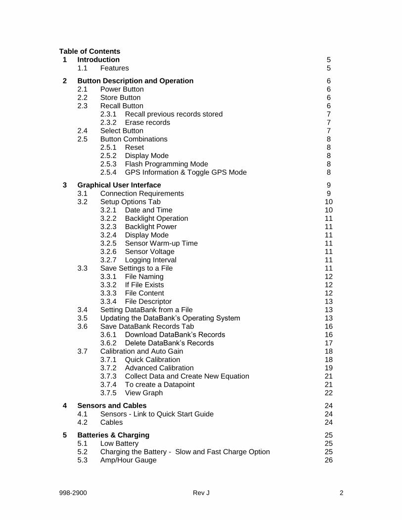
Table of Contents 1 Introduction 5 1.1 Features 5
2 Button Description and Operation 6 2.1 Power Button 6 2.2 Store Button 6 2.3 Recall Button 6 2.3.1 Recall previous records stored 7 2.3.2 Erase records 7 2.4 Select Button 7 2.5 Button Combinations 8 2.5.1 Reset 8 2.5.2 Display Mode 8 2.5.3 Flash Programming Mode 8 2.5.4 GPS Information & Toggle GPS Mode 8
3 Graphical User Interface 9 3.1 Connection Requirements 9 3.2 Setup Options Tab 10 3.2.1 Date and Time 10 3.2.2 Backlight Operation 11 3.2.3 Backlight Power 11 3.2.4 Display Mode 11 3.2.5 Sensor Warm-up Time 11 3.2.6 Sensor Voltage 11 3.2.7 Logging Interval 11 3.3 Save Settings to a File 11 3.3.1 File Naming 12 3.3.2 If File Exists 12 3.3.3 File Content 12 3.3.4 File Descriptor 13 3.4 Setting DataBank from a File 13 3.5 Updating the DataBank’s Operating System 13 3.6 Save DataBank Records Tab 16 3.6.1 Download DataBank’s Records 16 3.6.2 Delete DataBank’s Records 17 3.7 Calibration and Auto Gain 18 3.7.1 Quick Calibration 18 3.7.2 Advanced Calibration 19 3.7.3 Collect Data and Create New Equation 21 3.7.4 To create a Datapoint 21 3.7.5 View Graph 22
4 Sensors and Cables 24 4.1 Sensors - Link to Quick Start Guide 24 4.2 Cables 24
5 Batteries & Charging 25 5.1 Low Battery 25 5.2 Charging the Battery - Slow and Fast Charge Option 25 5.3 Amp/Hour Gauge 26

998-2900 Rev J 3
Table of Contents cont. 5.4 Recharging When Not Enough Charge 26 5.5 When to Charge the Battery 26 5.6 When the Battery Does Not Charge Normally 26 5.7 Battery Life Estimate 27
6 Warranty 28 6.1 Terms 28 6.2 Warranty Service 28 6.3 Out of Warranty Service 29
Appendix A Specifications 31 B Setting up Window’s HyperTerminal 32 C Using HyperTerminal to Download Data Files 33

998-2900 Rev J 4
WASTE ELECTRICAL AND ELECTRONIC EQUIPMENT (WEEE) DIRECTIVE
Turner Designs is in the business of designing and selling products that benefit the well-being of our environment. Accordingly, we are concerned with preserving the surroundings wherever our instruments are used and happy to work with customers by complying with the WEEE Directive to reduce the environmental impact resulting from the use of our products. WEEE Return Process: To arrange the return of an end-of-life product, proceed as follows:
If you purchased your instrument through a Turner Designs Distributor please contact your local representative. They will instruct you where to return the end-of-life product. If you purchased your instrument directly from Turner Designs please contact Turner Designs Customer Service By Phone: 1-408-212-4041 or Toll Free: (877) 316.8049 By Email: Customer Service at [email protected] Turner Designs will provide a WEEE RMA Number, a Shipping Account Number, and a Ship to Address. Package and ship the product back to Turner Designs.
The product will be dealt with per Turner Designs’ end-of-life recycling program in an environmentally friendly way.

998-2900 Rev J 5
1 Introduction
The DataBank is designed for Interpretive Metering and Data Collection from Turner Designs’ Cyclops Submersible Sensors integrated with GPS location data. Used in conjunction with a PC, the DataBank software allows for easy setup, calibration and data retrieval.
"Interpretive Metering" converts the voltage output from sensors to units of choice.
"Data Collection" allows users to store up to 9,999 records manually or automatically which can be downloaded using a computer via USB.
The DataBank Handheld Datalogger P/N 2900-199 allows for easy transport during mobile field studies. DataBanks are sold with cables installed. Cables are available in lengths of 0.6, 5, 10, 25, and 50 meters.
1.1 Features
Multiple-Gain functions Auto gain between set gain values Default gain settings for Cyclops Submersible Sensors Manually assign gain values
Dual Calibration Modes Quick calibration: Computer assisted Advanced calibration: Manual Up to 16 calibrations stored
Data logging Automatic shut off between sampling intervals greater than 10 seconds
o Minimum logging interval 1 second o Maximum logging interval 4 days
Non-volatile data storage No loss in data or settings Store up to 9,999 records
Integrated Internal GPS Global Navigation Satellite System (GNSS): GPS and GLONASS Horizontal Position Accuracy: 2.5m
High power rechargeable battery Supplies power to DataBank and sensor Built-in battery charger with “amp/hour” gauge
Flash operating system Automatic upgrade notice and assistance from Windows software Upgrade made via USB
Durable housing Sealed, low force, snap action pushbuttons Enables easy one-handed operation, even with gloves.

998-2900 Rev J 6
2 Button Description and Operation
Note: There are two distinct ways to operate each of the four buttons. 1) “Press” which is to press the button and release it within 1 second. 2) “Hold” which is to press the button for a full second before releasing.
2.1 Power Button
The Power button is used to:
Turn the DataBank on and off o Press the Power button to turn the DataBank on. o Hold the Power button to turn the DataBank off.
Toggle the backlight
o Press the Power button to toggle the LCD’s backlight on and off while the unit is turned on.
End logging mode
o Press the Power button while the unit is in logging mode to stop logging.
2.2 Store Button
The Store button is used to:
Store data records o Press the Store button to store the current reading displayed.
Initiate logging mode
o Hold the Store button to start the logging mode.
The following will be displayed once logging mode has begun.
2.3 Recall Button
The Recall button is used to:
Recall stored records o Press the Recall button to display the last record stored.
Erase stored records
o Hold the Recall button to erase the last record stored.

998-2900 Rev J 7
2.3.1 Recall previous records stored.
Each time the Recall button is pressed the record stored number will decrement to the very first record stored. Continuous presses, after the first record stored has been reached, will increment to the last record stored.
2.3.2 Erase records
Hold the Recall button to erase the last record stored and the display will first show,
Followed by,
Note: You can only erase the last record stored. Trying to erase any other record will result in the following message.
2.4 Select Button
The Select button is used to:
Select a parameter group o Press the Select button to increment through the parameter groups (1-16),
stop on the parameter group of choice and if no buttons are pressed after about a second that parameter group will be automatically selected.
Revert to the first parameter group
o Hold the Select button to revert to the first parameter group so you don’t have to scroll through the remaining parameter groups.
2.5 Button Combinations
2.5.1 Reset
Pressing all 4 buttons simultaneously will result in a hardware reset of the DataBank. This is used in the event that the computer locks up preventing a normal power down of the DataBank. This can also be used after updating the DataBank’s operating system.
2.5.2 Display Mode
Press the Select button and within one second press the Recall button to toggle between “Title” mode and “Date & Time” mode. The unit will revert back to the original programmed display mode on the next power up.

998-2900 Rev J 8
2.5.3 Flash Programming Mode This mode is used to update the DataBank’s operating system. Updates are made using the standard USB DataBank cable. An RS232 serial cable connection is available as an option. See Section 3.5 “updating the DataBank’s operating system”.
2.5.4 GPS Information & Toggle GPS Mode
Press the Power and Recall button simultaneously to view the GPS information. The LCD will display a “No Fix” message indicating that the GPS is unable to establish a signal or a GPS location as shown below.: After 3 seconds the display will switch to the Toggle GPS Mode where you can press the Power and Recall button simultaneously again to turn the GPS on or off.
Note: GPS operation impacts battery life, to estimate battery life refer to Section 5.7.

998-2900 Rev J 9
3 Graphical User Interface
DataBank GUI software runs in Microsoft Windows and is used for communicating with and configuring the DataBank.
3.1 Connection Requirements
DataBank must be connected to a computer using the provided interface cable.
DataBank must be turned on.
The computer COM port must be set to any COM port 1-8. NOTE: The DataBank’s Interface cable should not be connected to an external power source charging when connecting to the DataBank GUI.
When the above two requirements are fulfilled, begin the software and the GUI will search for the presence of a DataBank; port settings aren’t required.
If the DataBank is not found, then the following message will appear:
This message
indicates the GUI
is searching for a
connected
DataBank
This message
indicates the GUI
is searching for a
connected
DataBank
This message
indicates the GUI
is searching for a
connected
DataBank

998-2900 Rev J 10
If you click Retry, then the GUI again tries to find the DataBank. If you click Cancel, then the GUI software will shut down and you must re-start the GUI. Once communication has been established, the main screen will display the DataBank’s information in the upper left hand corner and the “Talking with DataBank” prompt will disappear:
3.2 Setup Options Tab
The Setup Options tab is used for setting the general operation of the DataBank. Each DataBank will have its own saved settings and this screen will change to reflect those settings once communication between a PC and a DataBank has been established. Note: Please wait for the background of each pull-down menu to turn light blue before attempting any changes.
3.2.1 Date and Time
PC Time – click to choose, then click Send to set the DataBank’s current date and time to PC date and time.
Upon connection,
the DataBank’s serial
number and version of
the operating system
are displayed
Upon connection,
the DataBank’s serial
number and version of
the operating system
are displayed

998-2900 Rev J 11
Manual Entry – click to choose, enter in a date and time, then click Send to set the DataBank’s current date and time to the manually entered date and time.
3.2.2 Backlight Operation
Manual – the Power button can be pressed to manually turn the backlight on/off.
Auto Shut-Off – use the pull down menu to set a time interval to automatically turn off the backlight.
3.2.3 Backlight Power
High – uses 30 mA power consumption Low – uses 15 mA power consumption
3.2.4 Display Mode
Date & Time – DataBank will display the date & time during normal operation Example: #01 04/06 10:32.
Title – DataBank will display the title of your current selection. Example: Amazon River
3.2.5 Sensor Warm-up Time
Set a time from the pull down menu which allows the sensor to stabilize “warm up” after power has been supplied and before any readings are taken. Note: Recommended Cyclops warm up time is a minimum of 5 seconds.
3.2.6 Sensor Voltage
Set the voltage that the DataBank should apply to the sensor upon power up. Setting a value near the minimum voltage required for operation will conserve the DataBank’s battery power and extend battery life. Note: Recommended Cyclops voltage input is 12 volts and a minimum of 5 volts.
3.2.7 Logging Interval
Enter a time interval (HH:MM:SS) that defines when the DataBank should wake the sensor to make a measurement. Note: If the logging interval is less than 10 seconds the DataBank screen will remain on. If the logging interval is greater than 10 seconds the DataBank screen will shut off and turn on before a reading is taken as a power saving feature.
3.3 Save Settings to a File
This button will open a new window with commands for specifying to the DataBank where and what to save to a file.

998-2900 Rev J 12
3.3.1 File Naming
Either manually enter a file path and filename and press Enter or use the Browse button to select an already existing filename from a desired location. Note: It is suggested you use the file extension .txt when manually entering a filename as the file is comma delimited. If a file path and filename are not entered or an already existing file is not selected, the setting file will be saved to the DataBank GUI folder found in the Programs Files folder within the C drive. From there it can be moved to a different location as specified by the end user. Note: If you are unable to find the file where the settings were saved you may need to use Notepad or similar program and create a .txt file. Be sure to type at least 1 character in the file before saving it.
3.3.2 If File Exists
Upon saving a settings file, the choices for the If File Exists section of the screen will either be selectable or unavailable depending on if the file exists for that file path entered.
Replace – the existing settings file is overwritten using new settings and calibration data.
Append – new settings and calibration data are appended to the existing file.
3.3.3 File Content
Users can either choose to save all the settings or selected settings.
All Settings – saves all settings and calibration data from all 16 parameter groups. Note: This may take several minutes.
Selected settings – allows options to include or exclude settings data and/or range of groups to save. If this option is chosen, the following screen will appear:
Range of Groups to Save – set the first group number and last group number to select the range of parameter groups to save. Calibration data for the selected range of parameter groups will be saved to file.
Include Setup Options – choose Yes to include or No to exclude the DataBank’s current settings to be saved along with calibration data for the range of groups selected.

998-2900 Rev J 13
Note: If you choose to save only groups 1 and 3, excluding group 2 and 4-16, then choose range of groups as (1,1) and repeat the same steps for range of groups (3,3) making sure to append group 3 data to group 1 data.
3.3.4 File Descriptor
This is a string of text written to the top of a file to help users better identify the settings or calibration data saved for that part of the file. A file descriptor is automatically generated and can be changed manually to any title the user desires:
3.4 Setting DataBank from a File
The DataBank can be set using a previously saved file which includes settings and/or calibration data.
1) Use the Browse button to navigate to an already existing file that contains
settings and/or calibration data. 2) Click Open to choose that file.
An error message will appear in an Error Message box if the chosen file is not a valid file. If the file chosen is a valid settings file, the descriptor set by the user will be displayed in a File Description box.
3.5 Upgrading the DataBank’s Operating System
Note: Be sure the DataBank's battery is fully charged before proceeding. New DataBank software releases for Windows will include the latest DataBank operating system files. When a DataBank with an older operating system is connected to a computer that has DataBank software containing new operating system files, the following upgrade frame will open:
Click OK to allow the upgrade or CANCEL to continue into the Windows software using the older operating system. Alternately, users can manually update the DataBank by entering NewDBOS in the logging interval box under the Setup Options Tab and then clicking Send or pressing Enter.

998-2900 Rev J 14
The following screen will appear:
Note: Both of the methods for upgrading will result in the screen above. Click the Browse button to navigate to a valid Hex file. Valid Hex files begin with a DB and end with (.hex) and contain the operating system’s version within the filename. For example, DB3xx.hex is a valid Hex file that can be used to update the DataBank’s operating system to version 3.xx
After a Hex file is chosen, click OK again to go to the Initialize DataBank for Upgrade screen. If a valid file is chosen then the screen below will appear.
Follow the instructions as outlined in the screen above to initialize the DataBank for upgrading.
Note: There are two potential issues that can arise with upgrading the Hex file.
A file error window appears. The cause is the Hex file chosen isn’t correctly named. This error can be ignored by clicking OK. A file warning window appears instead of the screen above. The cause is the Hex file chosen is not designed for use with the DataBank and a new file needs to be selected for the upgrade.
C:\DBVB\DB3xx.hexC:\DBVB\DB3xx.hex

998-2900 Rev J 15
Notes
If you fail an upgrade attempt, press all four buttons simultaneously and release them to reset the DataBank. Then turn the DataBank on and repeat the above procedure.
In case of serious failure where the DataBank will no longer power up normally,
contact Turner Designs Technical Support department: Phone: 1 (877) 316-8049 Email: [email protected]
Once the programming mode has been entered the following screen will appear:
Once the upgrade has completed the following screen will appear:
Simply follow the instructions in the window to reset the DataBank and return to normal operation.
Version 3 Loader Found.Version 3 Loader Found.

998-2900 Rev J 16
3.6 Save DataBank Records Tab
This section is used to download and save to file or erase data records from the DataBank.
The following screen shows all the functions available for this section:
3.6.1 Download DataBank’s Records
File Naming Either manually enter a file path and filename and press Enter or use the Browse button to select an already existing filename from a desired location. Note: It is suggested you use the file extension .txt when manually entering a filename as the file is comma delimited.
Excel users: when importing these data files into Excel, it is suggested that they be imported as ANSI Comma Delimited text files.
If File Exists – choose to either add downloaded data to an existing file using the Append option or replace it entirely using the Replace option.
Records to Download – choose the method for downloading data from the DataBank in the order they were stored, sequentially, or from a selected group.
All Records, as Stored
o will download data in the order they were stored (1-9999) All Records, Sequentially
o will download data stored for parameter group 1 first, then parameter group 2, then parameter group 3, and so on for all 16 parameter groups
Selected Group Only
o will download data stored for selected parameter group

998-2900 Rev J 17
Note: If Selected Group Only is chosen, the title of that parameter is displayed next to the parameter group’s number.
Click on Download DataBank’s Records and the following screen will open:
The record shown in the window’s box is listed in the following order: 1) Record # 2) Parameter Group # and range used (x1=High, x10=Med, x100=Low) for
measurement 3) Date and Time (24 hour clock) 4) Sensor mV 5) Calculated Value. 6) Latitude Note: For values measured with GPS enabled. 7) Longitude Note: For values measured with GPS enabled. Numeric progress can also be viewed on the DataBank’s LCD display. Once the files are downloaded you should confirm that the data is in the file prior to deleting the records. Note: If there is no data in the file or no file saved in the location you will need to create a .txt file in Notepad or similar application and save it to a location such as your desktop. You should enter at least 1 character in this file. Repeat step 3.6.1 If a File Exists.
3.6.2 Delete DataBank’s Records
Click on the Delete DataBank’s Records to open the following screen:
You will need to confirm the deletion of all DataBank Records before the operation will begin. Click Cancel Deletion to cancel your request and keep DataBank’s Records intact.
998-2900 Rev J 18
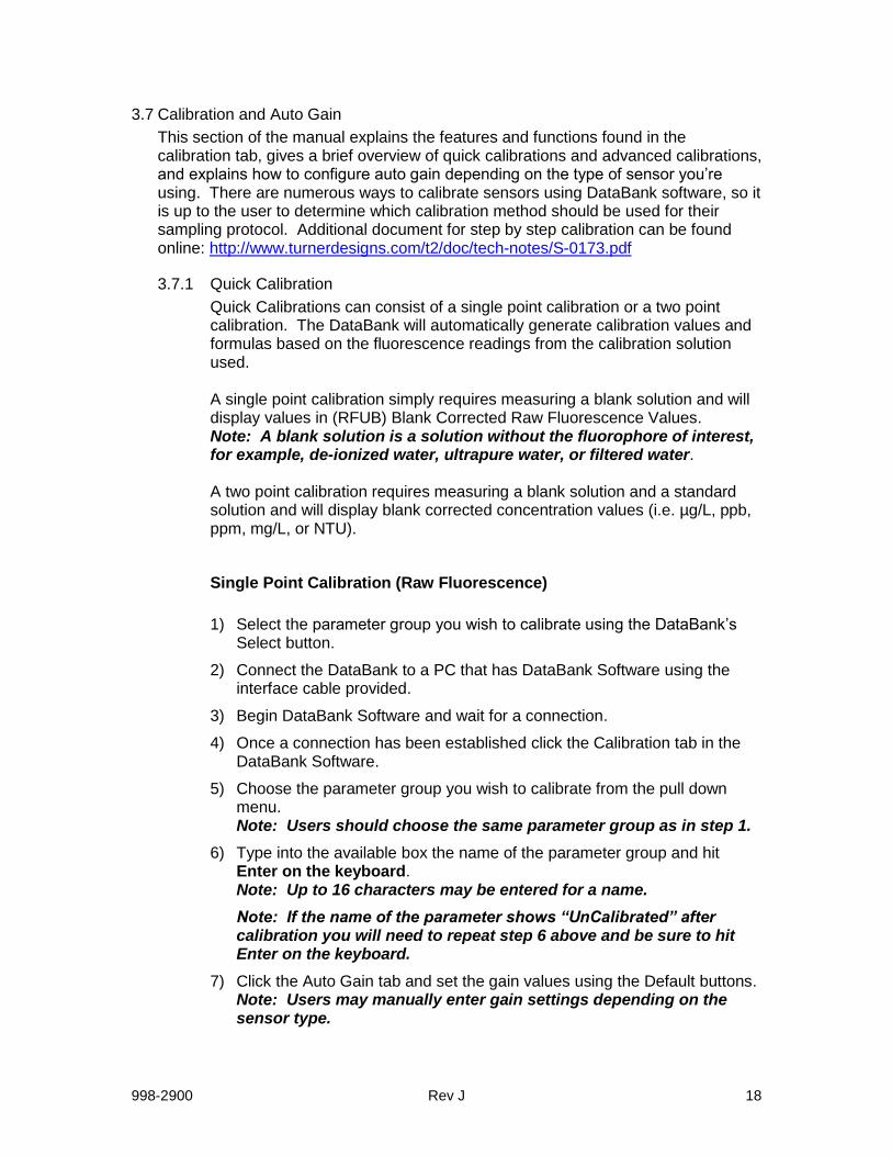
3.7 Calibration and Auto Gain
This section of the manual explains the features and functions found in the calibration tab, gives a brief overview of quick calibrations and advanced calibrations, and explains how to configure auto gain depending on the type of sensor you’re using. There are numerous ways to calibrate sensors using DataBank software, so it is up to the user to determine which calibration method should be used for their sampling protocol. Additional document for step by step calibration can be found online: http://www.turnerdesigns.com/t2/doc/tech-notes/S-0173.pdf
3.7.1 Quick Calibration
Quick Calibrations can consist of a single point calibration or a two point calibration. The DataBank will automatically generate calibration values and formulas based on the fluorescence readings from the calibration solution used.
A single point calibration simply requires measuring a blank solution and will display values in (RFUB) Blank Corrected Raw Fluorescence Values. Note: A blank solution is a solution without the fluorophore of interest, for example, de-ionized water, ultrapure water, or filtered water.
A two point calibration requires measuring a blank solution and a standard solution and will display blank corrected concentration values (i.e. µg/L, ppb, ppm, mg/L, or NTU).
Single Point Calibration (Raw Fluorescence)
1) Select the parameter group you wish to calibrate using the DataBank’s
Select button.
2) Connect the DataBank to a PC that has DataBank Software using the interface cable provided.
3) Begin DataBank Software and wait for a connection.
4) Once a connection has been established click the Calibration tab in the DataBank Software.
5) Choose the parameter group you wish to calibrate from the pull down menu. Note: Users should choose the same parameter group as in step 1.
6) Type into the available box the name of the parameter group and hit Enter on the keyboard. Note: Up to 16 characters may be entered for a name.
Note: If the name of the parameter shows “UnCalibrated” after calibration you will need to repeat step 6 above and be sure to hit Enter on the keyboard.
7) Click the Auto Gain tab and set the gain values using the Default buttons. Note: Users may manually enter gain settings depending on the sensor type.

998-2900 Rev J 19
8) Click the Calibration tab. The DataBank’s display should show Low, Med, or High in the top right hand corner. Note: If a lower case “s” is displayed followed by 4 numbers then repeat step 7.
9) Place the sensor in your blank solution and click “OK – proceed to step 2”.
10) The Software will start measuring the blank signal for each gain.
11) When blanking has finished click “OK – proceed to step 3”.
12) From the pull down menu choose RFUB (Raw Fluorescence Units Blanked) and click “Finalize Calculations”.
13) The following screen will appear when finalizing calculations has completed.
14) Click OK.
15) The DataBank is now ready for use and you may begin measuring samples. Values are reported as Blank Corrected Raw Fluorescence Units (RFUB).
Two point Calibration (Direct Concentration)
1) Follow steps 1-11 from Single Point Calibration Section.
2) Put your sensor in a standard solution of a known concentration.
3) Enter the concentration value of your standard solution in the Enter Standard Value box.
4) From the pull down menu choose units of measure or manually enter units of choice; maximum 4 characters.
NOTE: DO NOT CHOOSE RFUB.
5) Click “Proceed to step 4”.
6) The Software will start measuring the standard solution’s signal.
7) When completed, click “Finalize Calculations”.
8) Click OK.
9) The DataBank is now ready for use and you may begin measuring samples. Values will be reported in units that were set in Step #4.
3.7.2 Advanced Calibration
Advanced calibration allows users to calibrate sensors using multiple standard solutions for increased accuracy of measurement. Users can take

998-2900 Rev J 20
advantage of this calibration which will generate interpretation equations based on data collected from multiple standard solutions. Users may also manually enter values to be used in interpretation equations for calculating sample concentrations.
Group number – although a number 1 is displayed in this section, you must access the pull down menu that lists numbers 1-16 (representing the 16 parameter groups) and select a number. This will prompt the DataBank to download calibration settings, values, and equations for that parameter group and allow users to continue with the calibration for that parameter group.
Date – displays the last date the selected parameter group was modified or calibrated. This date is automatically updated and stored when any modifications are made to the parameter group’s settings.
Units – are either set during quick calibration or manually entered in this box with a maximum limit of 4 characters (e.g. ppb, ppm, µg/L, NTU, etc.). Title – is what will be displayed for the selected parameter group when the DataBank is set to Title Mode instead of Date & Time Mode. Users can set this title to either describe the formula used in the calibration or the parameter group being calibrated. This box has a maximum limit of 16 characters (e.g. Amazon River, RWT RFUB, etc.). Gain – selections from this pull down menu reflect the gain settings that were configured in the Auto Gain tab. Each Gain will have its own interpretation equation. Interpretation Equation – uses the values entered in each box to convert the sensor’s readings into concentration values for the units specified. Values may be entered manually or automatically upon completion of a calibration. Note: Changing the formula values or (post)-calibrating after data has been collected for that parameter group will affect all stored data for that parameter group. It is recommended that the equation’s values be recorded in a log or SAVE setting to a file after calibration is complete.

998-2900 Rev J 21
mV or mA – Only mV can be chosen for the Cyclops sensors.
Dec. or S.N. – allows users to choose either decimal or scientific notation as the numeric format for displaying the equations.
3.7.3 Collect Data and Create New Equation
This calibration generates an interpretation equation using multiple data points. The interpretation equation generated is specific to the gain selected in the Advanced Calibration screen. Each gain selection should have its own interpretation equation.
3.7.4 To create a Datapoint:
1) Place the sensor in a solution of known concentration
Note: If the mV reading is 4905, then the concentration of that solution is too high to be read on the current gain setting. Either dilute the solution to a lower concentration or use a different gain setting.
2) Enter the concentration of the solution in the appropriate box
3) When mV reading has stabilized, click “Make Datapoint 1” to create a datapoint
4) Repeat steps 1-3 for the remaining solutions you intend to use for calibration of the current gain setting
Note: After creating a datapoint the “Make Datapoint” button will increment displaying the number of the next available datapoint.
5) Once two data points have been entered you’ll be able to view your
results graphically by clicking View Graph. See Section 3.7.5.
Source of Sensor Readings – by choosing the manual entry button users are able to enter mV values for the corresponding concentration values entered.

998-2900 Rev J 22
Cancel calibration – causes the loss of all currently created data points. If this button is clicked you will have to confirm the operation that has been chosen.
3.7.5 View Graph
This section allows users to choose the type of equation to fit through their data points, to force fit the equation, view the equation chosen, print the graph, accept the equation, or go back to add data points.
A minimum of two points is required to access the View Graph screen.
Type of Equation – defines the number of terms used in creating the formula. You can choose from 1st, 2nd, or 3rd Order equations while viewing the graphed results and the curve will shift accordingly. Force thru First – allows users to force the calibration curve through the first calibration point on the curve (point closest to zero). View Equation – displays the equation Order and calibration coefficients for the calibration curve being viewed.
Add Data Points – allows you to go back to the previous screen and continue to store more calibration points or cancel the calibration being performed. Accept Equation – click the Accept Equation button to accept the calibration and store calibration data for that parameter group in the DataBank’s memory. Upon clicking this button you will be returned to the Equation Groups and Calibration Screen.

998-2900 Rev J 23
ADDITIONAL GRAPH FEATURES Move the mouse pointer over the plotted line and/or data point and the (x,y) values will be displayed. Delete Data Point – move the mouse pointer over the data point you wish to delete and click the mouse button. Verify the value you wish to delete is displayed in the box to the left of the graph. Click the Delete Data Point button and that data point will be removed from the plot. Set New Value – move the mouse pointer over the data point you wish to change and click the mouse button. Verify the value you wish to change is displayed in the box to the left of the graph. Enter a new X and/or Y value for that data point, click the Set New Value button, and that point will be adjusted to the (x, y) coordinates you entered. Cancel – click the Cancel button to return to the previous View Graph section Print Graph – click the Print Graph button to open a page setup window that will allow you to set up the margins, paper source, etc.; the printed calibration will include titled data points, calibration coefficients, the calibration equation, and the title of the parameter group, similar to the figure to the right.

998-2900 Rev J 24
4 Sensors and Cables
This section discusses the sensors and cables for the DataBank.
4.1 Sensors The DataBank can be configured to work with Turner Designs Cyclops Sensors. For information on how to configure the DataBank to work with Cyclops visit the following web address: DataBank with Cyclops Sensors http://www.turnerdesigns.com/t2/doc/manuals/998-2901.pdf
4.2 Cables
The DataBank comes configured with a sensor cable installed. Turner Designs cables are available in 0.6, 5, 10, 25, and 50 meter lengths. The following are cable part numbers for use with Cyclops sensors: P/N 105-2580 0.6 meter cable with locking sleeve P/N 105-0585 5 meter cable with locking sleeve P/N 105-0581 10 meter cable with locking sleeve P/N 105-0582 25 meter cable with locking sleeve P/N 105-0583 50 meter cable with locking sleeve
Note: The Handheld DataBank Datalogger P/N 2900-199 handle is sealed with Marine Goop to improve protection for moisture and humidity. If the cable needs to be removed or replaced this seal will be broken. Turner Designs advises the use of Marine Goop to reseal the handle.

998-2900 Rev J 25
5 Batteries & Charging
5.1 Low Battery
When the DataBank’s battery is low, “Low Battery” will be displayed for a second, every 4 seconds until the battery is either recharged or gets too low for continued use. Note: At first indication of a low battery, assisted GPS power is discontinued.
5.2 Charging the Battery
The battery may be charged using either the AC to DC power charger or the 12 volt car adapter power charger. To charge the DataBank’s battery plug in the DataBank’s interface cable. Apply power using one of the supplied power chargers.
Selectable charge rate:
When charging, pressing the SELECT button will toggle between SLOW and
FAST charge modes, charging at typically 1.0 or 2.0 amps respectively.
SLOW mode is designed to terminate at roughly 90% of a full charge. This
mode helps increase the life of the battery significantly. Use of the SLOW
mode is recommended.
Fast mode attempts to fully charge the battery as quickly as possible.
New display format:
The LCD shows the charge mode - FAST or SLOW, the current being
delivered to the battery, the temperature of the battery, the elapsed charge
time, and an estimate of the power (amp-hours) accepted by the battery.
Pulse mode:
Upon completion of a charge the display will flash DONE, and pulse charging
will begin. Pulse charging prevents the battery from self-discharging,
maintaining the new charge indefinitely. Every tenth second, the battery
receives a one second charge pulse. The display will also show PULSE during
that second. This allows for overnight or weekend charging without concern of
over-charging.

998-2900 Rev J 26
5.3 Amp/Hour Gauge
The Amp/Hour gauge is used to help you estimate the percentage of battery capacity used [% battery consumed = 25 * (amp hours used)].
The amp/hour gauge is only an estimation of actual acceptance. At full charge the NiMH battery may retain 85%, but at the lowest rate only about 62% of the full charge dumped into it, which is based on the rate of change. The DataBank is designed so that the most efficient charge occurs during the first hour of charging (about half of a complete charge) due to temperature effects.
Monitoring the amount of amp/hours replaced during each charge will give you a better understanding of how much energy is used from the battery on a daily basis.
5.4 Recharging when Not Enough Charge
If you feel the battery did not receive as much of a charge as it should have (for example, termination due to “ot”), unplug the charger, turn off the DataBank, and wait for the batteries to cool down. Once the batteries have cooled, plug in the charger. Amp/hours will continue to be added to the gauge from where it previously left off.
5.5 When to Charge the Battery
It is most efficient to charge the batteries when the DataBank is only partially discharged because the charger uses a rapid charging scheme. It may be good to start by charging it every day.
Manufacturer’s specifications:
If batteries are stored, fully charged, between -4 to 86 F (-20 to 30 C), they should be recharged every 3 - 6 months if not used.
The batteries are rated for a minimum of 500 recharges.
Note: If batteries are allowed to completely self-discharge, their energy storage capacity will be reduced.
5.6 When the Battery Does Not Charge Normally
If the DataBank has been stored for a long period of time and the battery is exhausted, attaching the charger may appear to have no effect.
Without sufficient battery power the DataBank will not start up normally, however the battery does receive a pulse of charge upon connection. Disconnect and reconnect every 30 seconds to give the battery a pulse charge of 2 amps, quickly tapering down to 0, and repeat this several times to boost the battery allowing the DataBank to start up normally and begin displaying the normal “CHARGING” mode.

998-2900 Rev J 27
5.7 Battery Life Estimate
Below is an estimate of battery life for the DataBank Handheld Datalogger with and without the internal GPS turned on using the Cyclops 7F sensors. Note: This is a rough calculation and the recommended best estimate is to test for your specific parameters prior to deployment.
Continuous battery life estimate in hours with GPS data collection
CDOM/FDOM 4 Phycocyanin 5
Chlorophyll in vivo 4 Phycoerythrin 4
Fluorescein Dye 5 PTSA Dye 3
Oil - Crude 4 Rhodamine Dye 5
Oil - Fine 2 Tryptophan 3
Optical Brighteners 4 Turbidity 6
Continuous battery life estimate in hours without GPS data collection
CDOM/FDOM 8 Phycocyanin 12
Chlorophyll in vivo 8 Phycoerythrin 7
Fluorescein Dye 13 PTSA Dye 6
Oil - Crude 8 Rhodamine Dye 11
Oil - Fine 4 Tryptophan 3
Optical Brighteners 10 Turbidity 16

998-2900 Rev J 28
6 Warranty
6.1 Terms
Turner Designs warrants the DataBank and accessories to be free from defects in materials and workmanship under normal use and service for a period of 12 months from the date of shipment from Turner Designs with the following restrictions:
Turner Designs is not responsible for replacing parts damaged by accident or neglect. Your instrument must be installed according to instructions in the User’s Manual. Damage from corrosion is not covered. Damage caused by customer modification of the instrument is not covered.
Note: The Handheld DataBank is NOT fully waterproof or water-resistant and extra care should be taken to protect it from the elements. Damage from water intrusion is not covered.
This warranty covers only Turner Designs products and is not extended to equipment used with our products. We are not responsible for incidental or consequential damages, except in those states where this limitation is not allowed. This warranty gives you specific legal rights and you may have other rights which vary from state to state.
Damage incurred in shipping is not covered.
6.2 Warranty Service
To obtain service during the warranty period, the owner shall take the following steps:
1. Write, email or call the Turner Designs Technical Support department and
describe as precisely as possible the nature of the problem.
Phone: 1 (877) 316-8049 Email: [email protected]
2. Carry out any adjustments or tests as suggested by the Technical Support Department.
3. If proper performance is not obtained you will be issued a Return Materials
Authorization number (RMA) to reference. Package the unit, write the RMA number on the outside of the shipping carton, and ship the instrument, prepaid, to Turner Designs. If the failure is covered under the warranty terms, the instrument will be repaired and returned free of charge, for all customers in the contiguous continental United States. For customers outside of the contiguous continental United States who purchased equipment from one of our authorized distributors, contact the distributor. If you purchased directly, contact us. We will repair the instrument at no charge. Customer pays for shipping duties and documentation to Turner Designs. Turner Designs pays for return shipment (custom duties, taxes and fees are the responsibility of the customer).

998-2900 Rev J 29
6.3 Out of Warranty Service
Follow steps for Warranty Service as listed above. If our Technical Support department can assist you by phone or correspondence, we will be glad to, at no charge. Repair service will be billed on a fixed price basis, plus any applicable duties and/or taxes. Shipment to Turner Designs should be prepaid. Your bill will include return shipment freight charges.
Address for Shipment: Turner Designs, Inc.
1995 N.1st Street San Jose, CA 95112

998-2900 Rev J 30
Equipment Specified as Electrical and Electronic Waste

998-2900 Rev J 31
Appendix A: Specifications
DataBank Handheld Datalogger
Current draw Total: ≤ 120 mA; Sleeping = < 65 µA
Charge Time < 3 hours for a fully discharged battery; ambient @ 25 C
Slow charge mode recommended to extend battery life.
Battery Life Continuous up to 15 hours dependent on installed sensor/settings.
GPS Data Collection continuous up to 5 hours
Selectable Sensor Parameters
Voltage: Software selectable 3 – 12 volts
Warm-up Time: 0-5 minutes
4 Programmable Ranges
Sensor Input Range: 0-5 volts or 0-20 mA
Resolution:12 bit
Global Navigation GPS & GLONASS
Horizontal Position Accuracy: 2.5m
Memory Storage Non Volatile, 1280 kb
9,999 records; 1 record = sensor reading, date, time and location
Communication USB
Physical
Main body: 4.6"W x 3.2"H, x 3.4"D, Handle: 4.8" long.
(117mm W x 81mm H x 86mm D, Handle 122mm)
Overall: 11"H (279 mm H) with handle, strain-relief and connector
Weight: 1.7 lb. (.76 kg) w/o cable
Operating Temperature
0-50 °C.

998-2900 Rev J 32
Appendix B: Setting up Window’s HyperTerminal
To assist HyperTerminal users, a settings file has been included on the USB flash drive that configures HyperTerminal for use with DataBank. Note: COM port is not set by included setting file. Copy this file from the USB flash drive into the folder or directory of choice. We recommend copying this file to the DataBank’s folder that was set up during DataBank software installation:
C:\Program Files\DataBank GUI
1) Right click on this file and choose properties to change COM port settings. 2) Click on Connect To tab. 3) Use the Connect Using pull down menu to select the COM port you wish to set
if you are using a port other than COM port 1. 4) To verify communication with the DataBank turn the DataBank on and make sure
it is attached to the set COM port. 5) Type using upper case letters “RST” in the HyperTermial window and hit Enter.
You should get the following response:
“Turner Designs Instruments; Firmware Ver. 3.xx MM/DD/YY; S/N 2900XXX MM/DD/YY”.
When HyperTerminal is started via “DataBank.ht”, it is initialized with the following settings:
Connected using: Direct Connect using COM 1 Bits/sec: 9600 Data bits: 8 Parity: none Stop bits: none Flow Control: hardware Function, arrow, and control keys are used as: Terminal Keys Backspace key sends: Ctrl H Emulation: Auto Detect Telnet Terminal: ANSI Backscroll buffer lines: 250 Line Delay: 100 ms Character Delay: 10 ms Append line feeds Wrap lines that exceed terminal width

998-2900 Rev J 33
Appendix C: Using HyperTerminal to Download Data Files
Open HyperTerminal (see Appendix B) Note: All letter entries must be in UPPER CASE.
1) Type the command “DLD s”.
o “s” is the sort character, O thru F for curves 1-16 or S for sequential o “SPACE” (or any other character) will retrieve unsorted data
2) Press Enter. The display on the DataBank should show “Downloading” followed
by “0000 of xxxx”.
o “0000” is the current record number o “xxxx” is the total number of records to be downloaded
Note: The record number will not be incrementing at the time since the actual downloading has not yet started.
3) Now, in your terminal program, select Transfer then Capture Text. 4) Enter a filename with a .txt extension and press start. 5) Press Ctrl-Q on the keyboard to start the flow of data; you will be able to see
progress in Hyperterminal as the record number increments on the DataBank’s display.
Note: During “sorted” downloads, the flow of data may stop for up to several seconds and this is normal. Keyboard Commands while downloading
o Ctrl-S – X-Off used to stop the download for up to 30 seconds o Ctrl-Q – X-On used to start the download o Ctrl-C – used to terminate the program o CSD – clear stored data is used to erase all stored records
6) Once download has completed select Transfer, Capture Text, then Stop.
Data File Example:
Each data line transferred will be in the following order, comma separated:
1) Record # 2) Parameter group # 3) Range (x1=High, x10=Med, x100=Low) 4) Date 5) Time 6) Sensor mV – raw voltage signal 7) Value – calibration based calculated value 8) Latitude 9) Longitude


![Klinische Richtlijn Turner Syndroom - VKGN richtlijn Turner... · Klinische Richtlijn Turner Syndroom Nederlands-Vlaams Multidisciplinair Netwerk Turner Syndroom Oktober 2012 [2]](https://img.pdfslide.net/doc/110x75/6051868ca1b38602122de530/klinische-richtlijn-turner-syndroom-vkgn-richtlijn-turner-klinische-richtlijn.jpg)