Embed Size (px)
Citation preview
November 2014 (as amended Nov 2016)
Wide
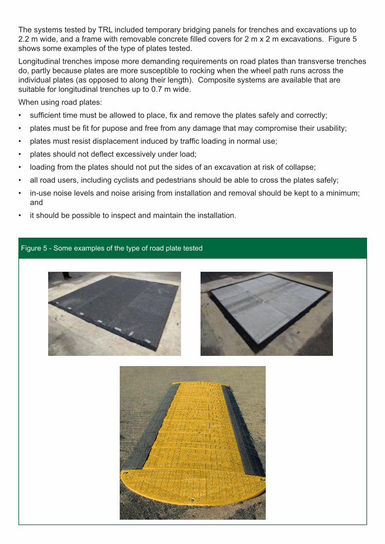
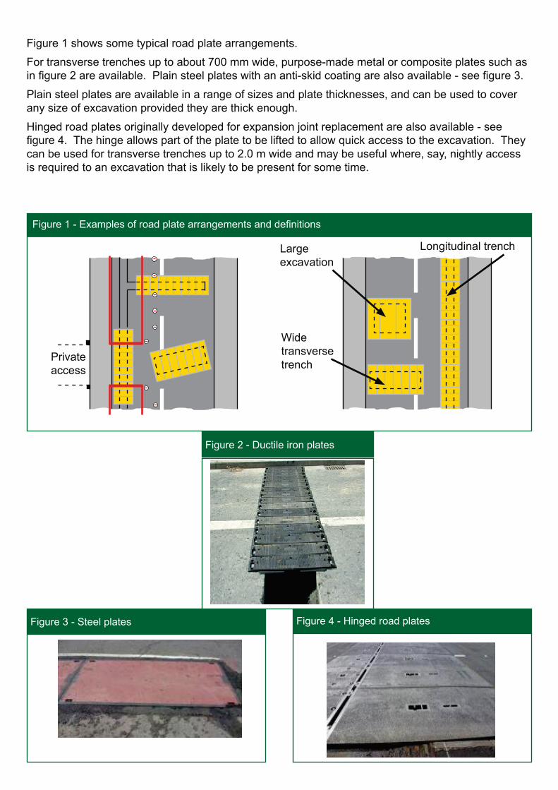
The systems tested by TRL included temporary bridging panels for trenches and excavations up to 2.2 m wide, and a frame with removable concrete filled covers for 2 m x 2 m excavations. Figure 5 shows some examples of the type of plates tested.
Longitudinal trenches impose more demanding requirements on road plates than transverse trenches do, partly because plates are more susceptible to rocking when the wheel path runs across the individual plates (as opposed to along their length). Composite systems are available that are suitable for longitudinal trenches up to 0.7 m wide.
When using road plates:
• sufficient time must be allowed to place, fix and remove the plates safely and correctly;
• plates must be fit for pupose and free from any damage that may compromise their usability;
• plates must resist displacement induced by traffic loading in normal use;
• plates should not deflect excessively under load;
• loading from the plates should not put the sides of an excavation at risk of collapse;
• all road users, including cyclists and pedestrians should be able to cross the plates safely;
• in-use noise levels and noise arising from installation and removal should be kept to a minimum; and
• it should be possible to inspect and maintain the installation.
Figure 5 - Some examples of the type of road plate tested
Figure 5 - Some examples of the type of road plate tested
British Standard BS 5975:2008+A1:2011 Code of practice for temporary works procedures and the permissible stress design of falsework is the main industry reference for temporary works procedures, including shoring excavations and using road plates.
Deciding when to use road platesThe time required for installation and removal is an important consideration in deciding whether or not to use road plates. Other factors to consider include:
• the overall duration of the works;
• the type, size and weight of the plates;
• the method of installation and removal;
• the type of installation (e.g. surface mounted or recessed);
• the method of supporting and fixing the plates;
• the possible need for additional trench shoring;
• the amount of equipment and materials that may have to be moved to facilitate the use of plates;
• the amount of traffic management equipment (barriers, cones etc.) that may have to be moved to open and close the carriageway; and
• whether or not it is necessary to lift every plate during the working window.
In general, using road plates will tend to increase the overall site occupation time as time spent installing and removing the plates may reduce the window for carrying out the works themselves. It is therefore important that the benefits of reduced congestion outweigh the impact of potentially extending the overall site occupation time. The cost associated with using road plates is another factor to consider.
Plant requirementsPlain steel road plates can be very heavy (for example, the smallest plate in Table 1 weighs around 200 kg) so in most cases they will need to be lifted and positioned by mechanical means. Road plates should be provided with suitable lifting points to allow them to be attached to lifting plant in a safe and stable manner. Owing to the difficulties in controlling large plates, particularly in wind, it may be necessary to increase the size of the safety zone so there is no risk of the plates swinging over a live carriageway or footway whilst being lifted into position.
Wherever practicable mechanical handling should be used although it may be possible to manually lift and position individual elements of proprietary road plate systems safely (e.g. interlocking, composite). Data on weights and instructions for handling must be obtained from the system supplier, and a manual handling assessment undertaken. See the Health & Safety Executive website (http://www.hse.gov.uk/msd/manualhandling.htm) for further advice.
Although it is possible to break out a plate recess using hand tools, it is likely to be quicker and neater to use a mini planer. Forming recesses mechanically tends to reduce the amount of bedding material required as less virgin material is disturbed. Drilling equipment may be required to form holes for plate fixings.
Types of plate
Large plain steel plates may need to be placed on bedding material, whether they are surface mounted or recessed. Each time they are replaced, it may be necessary to apply further bedding material and, where recessed, fill the gaps between the plates and the edges of the recess. Where asphalt ramps are used to smooth the transition from road to plate, they may need to be occasionally reformed during the life of the works in order to ensure they continue to be effective.
Depending on the design, modular plating systems can sit on bedding material or directly on the road. These plates can be removed quickly by simply unfixing them from their seatings and replacement is similarly straightforward.
Plating systems that use a frame take longer to install initially but once complete, the covers can be easily removed or replaced - no material is needed to replace disturbed bedding or fill gaps. It is important that the entire frame is uniformly supported and any gaps between the frame and the edges of the recess are filled to prevent horizontal displacement under loading.
In general, plates should not load excavation edges. Small plates tend to have integral supports located such that their loads are transmitted away from the edges of the excavation. Large plates should be supported on bedding that does not extend to edge of excavations
Wheel loadingApart from certain situations where the edge of the excavation can be loaded, the free span will be greater than the width of the excavation. For example, where the bedding is 200mm in from each side of the trench, the free span will be 400mm more than the trench width.
Road plates can be designed in accordance with BD 21/01 The Assessment of Highway Bridges and Structures taking into account the specified HA live load loading (a uniformly distributed load together with a knife edge load), single axle load and single wheel load. However, it is possible to derive a design load from first principles. The maximum bending moment and shear force that can be imposed on a single plate depends on:
• the length of the free span;
• the number of half-axles that can be accommodated within the free span;
• the weights of the half-axles; and
• the positions of the half-axles.
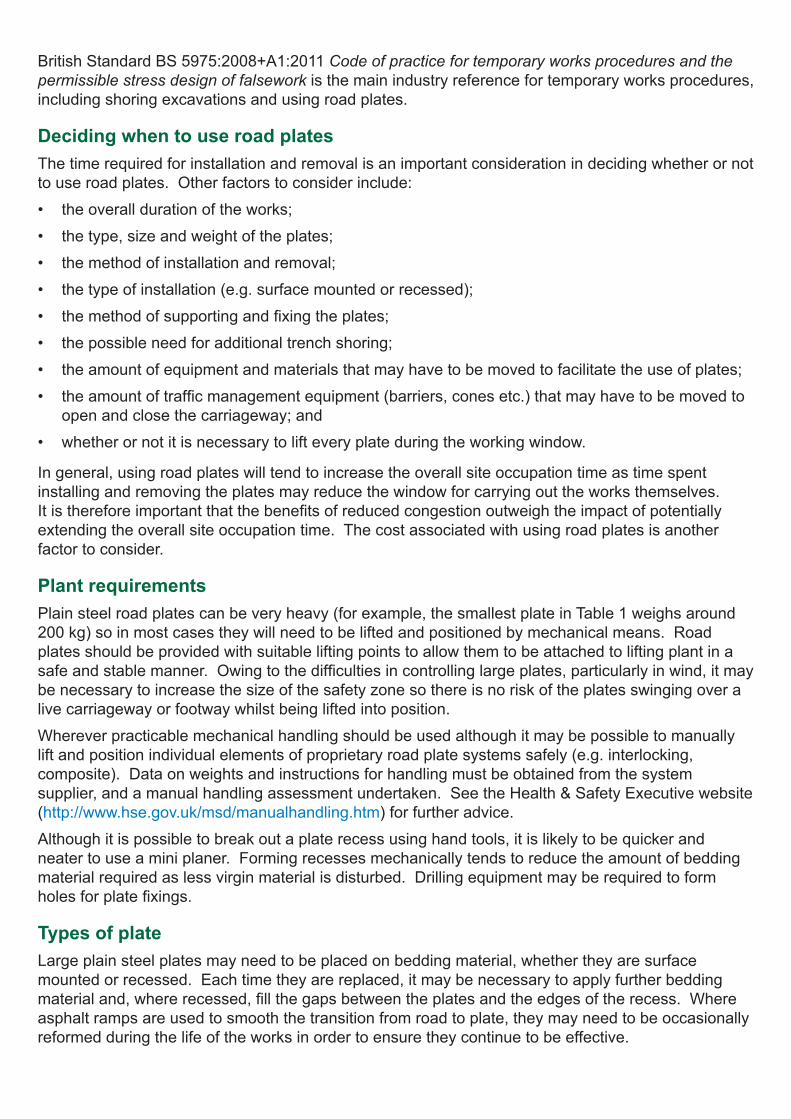
For relatively small plates, a single half-axle load will be all that can be physically accommodated, and maximum bending occurs when the load is at half span. For larger excavations it becomes possible for two axles to load the free span and the worst case is where the axles in question are the tandem drive axles of an articulated lorry. Figure 6 shows a series of loading cases based on these conditions. (Note that with tandem drive axles, one of the axles will be heavier than the other.)
In figure 6a, two half-axles are acting on the free span. However, the most severe imposed bending
Figure 6 - Plate loading examples
Figure 6 - Plate loading examples
(a) (b) (c)
Plate width Plate width
Tren
ch w
idth
Free
spa
nP
late
leng
th
stress is still likely to occur when the lighter half-axle is off the span and the heavier half-axle is at mid span (and at its edge) - see Figure 6b. Plates a little over 1.25 m wide can be loaded by half-axles from two adjacent vehicles, as shown in Figure 6c.
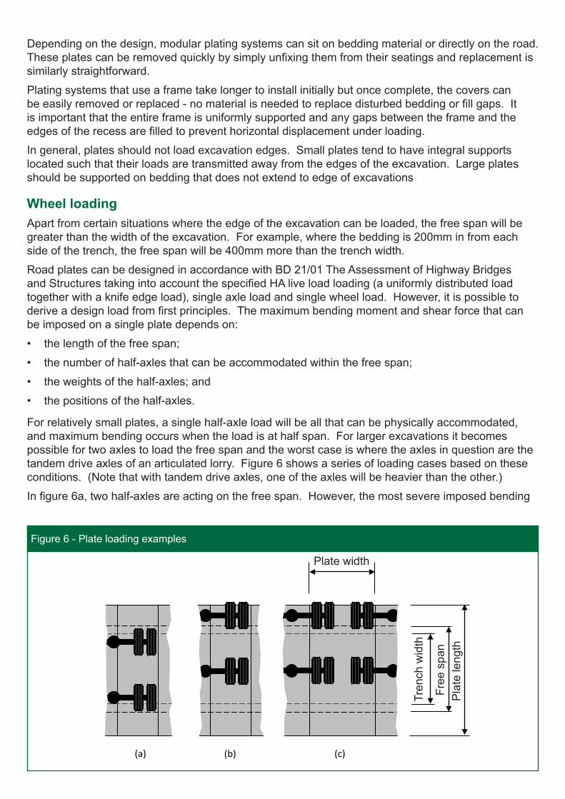
Information on design loading for plates is given by Jordan et al (2013) and Table 1 gives typical minimum derived plate thicknesses for simply supported 1 m and 1.25 m wide plain steel (Grade S275) plates carrying HGV loading. Actual thickness will depend on stock sizes available. For wider plates, where it becomes possible for two adjacent vehicles to load the plate at same time, the required thickness will need to be derived by calculation. Individual checks will be required to determine whether special order vehicles can cross a given arrangement of road plates.
Type of mounting Road plates can be surface mounted or recessed. Although in many situations surface mounted plates can be faster and easier to install (small road plates are mostly designed to be surface mounted), recessed plates have a number of advantages. Recessed plates are:
• generally more comfortable for road users to negotiate;
• better able to accommodate traffic moving at normal speeds;
• less likely to generate noise when crossed by vehicles, particularly HGVs; and
• inherently more stable and therefore less reliant on the performance of the fixings.
Surface mounted plates can render de-icing treatment ineffective as solid de-icers tend to be displaced before they have entered solution, so surface mounting might not be appropriate in freezing conditions. Surface mounted plates must not be used when snow ploughs are likely to be used.
For plates in the larger sizes, fully recessing the plates so that they lie flush with the road surface might not be practicable. Partial recessing can help here although the benefits of a fully recessed plate will not be fully realised.
Profile and speed considerationsThe temporary profile created by road plates and the method of fixing them will, depending on the orientation of traffic flow, determine the speed at which they can be crossed safely. Plates should not be crossed at speeds higher than those recommended by the manufacturer and enforcement or other measures may be required if this becomes an issue. As long as the running surface is no more than about 25 mm above the adjacent road surface and suitable ramps are provided, all vehicles should be able to cross securely fixed plates at speeds up to 30 mph. (Some specialist surface mounted hinged ramped plates are designed to be trafficked at speeds up to 70 km/h (43 mph) and these tend to have a ramp gradient of 4 to 6%.)
Where surface curvature is pronounced, small surface mounted road plate systems are more likely to match the road profile and do so without the need for bedding material (see figure 7a). Where large surface mounted plates are used, they can depart from the road profile significantly (see figure 7b). Asphaltic bedding material will generally be required to support the edges and prevent the plate
Plate width (m)
Free span (m)
0.7 0.8 0.9 1.0 1.2 1.4 1.6 1.8 2.0 2.4 2.8
1.0 22 24 25 27 30 32 35 37 40 43 47
1.25 20 21 23 24 27 29 31 33 35 39 42
Table 1 - Typical minimum plate thicknesses in mm
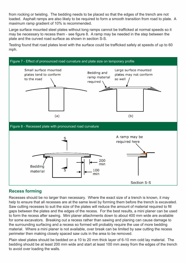
from rocking or twisting. The bedding needs to be placed so that the edges of the trench are not loaded. Asphalt ramps are also likely to be required to form a smooth transition from road to plate. A maximum ramp gradient of 10% is recommended.
Large surface mounted steel plates without long ramps cannot be trafficked at normal speeds so it may be necessary to recess them - see figure 8. A ramp may be needed in the step between the plate and the curved road surface as shown in section S-S.
Testing found that road plates level with the surface could be trafficked safely at speeds of up to 60 mph.
Recess forming Recesses should be no larger than necessary. Where the exact size of a trench is known, it may help to ensure that all recesses are at the same level by forming them before the trench is excavated. Saw cutting recesses to suit the size of the plates will reduce the amount of material required to fill gaps between the plates and the edges of the recess. For the best results, a mini planer can be used to form the recess after sawing. Mini planer attachments down to about 400 mm wide are available for some excavators. Breaking out a recess rather than sawing and planing can cause damage to the surrounding surfacing and a recess so formed will probably require the use of more bedding material. Where a mini planer is not available, over break can be limited by saw cutting the recess perimeter then making closely spaced saw cuts in the area to be removed.
Plain steel plates should be bedded on a 10 to 20 mm thick layer of 6-10 mm cold lay material. The bedding should be at least 200 mm wide and start at least 100 mm away from the edges of the trench to avoid over loading the walls.
Figure 7 - Effect of pronounced road curvature and plate size on temporary profile
Figure 8 - Recessed plate with pronounced road curvature
Some modular plating systems such as the bridging panels and frame and covers tested by TRL require deep recesses. However, there needs to be a sufficient thickness of in-situ bound material below the recess to support the plate. For example, a plating system that requires a 200 mm deep recess should generally only be considered where the bound road layers are approximately 400 mm deep.
FixingsChemical and expanding type fixings are widely available for attaching plates securely to concrete substrates. However, most plate installations are in fully flexible pavements and the effectiveness of the fixings depends more on the condition of the pavement than the fixings themselves. A road plate installation will tend to be more stable the less its performance depends on the fixings, and recessed plates perform well in this respect.
Generally, fixings should be placed as far away from the edge of the trench as possible. This helps reduce the effect of forces transmitted through the fixings (e.g. shear, pull-out) and particularly in the case of expanding bolts, the forces created by the fixings themselves.
On transverse trenches, road plates are well aligned to take dynamic loads. On longitudinal trenches, the load travels across the individual plates and the potential for them to rock is greater. This is more likely to be a problem with smaller plates and load sharing devices that limit rocking may be required. Plates must be secured to:
• prevent horizontal movement under braking and acceleration or from impact loading on protruding edges or ramps;
• resist uplift caused by dynamic rebound and flexure of the plates under wheel loading;
• prevent rocking; and
• withstand acts of vandalism or attempted theft.
Small, light plates are less stable than large heavy plates and they must be fixed in accordance with the manufacturer’s recommendations. Fixing arrangements will vary depending on the plate design and the manufacturer’s recommendations for the type and speed of traffic.
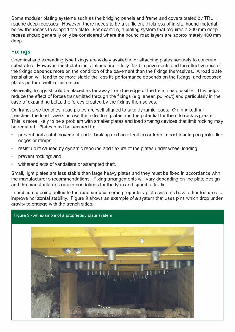
In addition to being bolted to the road surface, some proprietary plate systems have other features to improve horizontal stability. Figure 9 shows an example of a system that uses pins which drop under gravity to engage with the trench sides.
Figure 9 - An example of a proprietary plate system
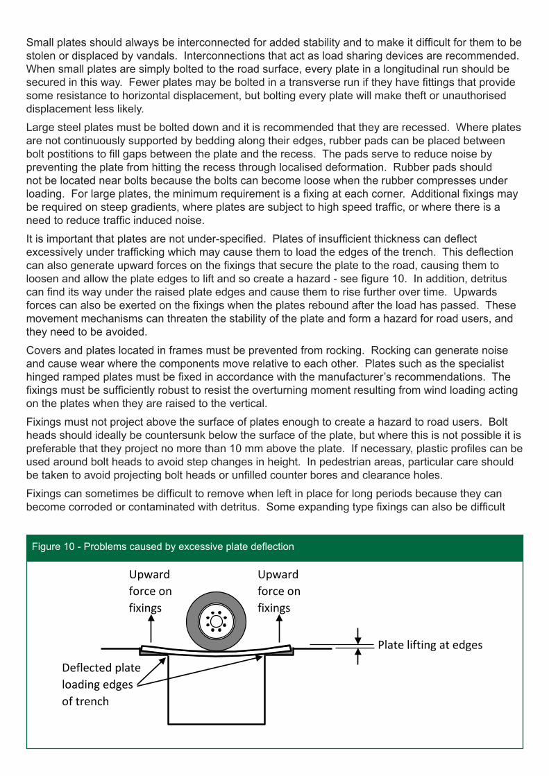
Figure 10 - Problems caused by excessive plate deflection
Deflected plate loading edges of trench
Plate lifting at edges
Figure 10 - Problems caused by excessive plate deflection
Upward force on fixings
Upward force on fixings
Small plates should always be interconnected for added stability and to make it difficult for them to be stolen or displaced by vandals. Interconnections that act as load sharing devices are recommended. When small plates are simply bolted to the road surface, every plate in a longitudinal run should be secured in this way. Fewer plates may be bolted in a transverse run if they have fittings that provide some resistance to horizontal displacement, but bolting every plate will make theft or unauthorised displacement less likely.
Large steel plates must be bolted down and it is recommended that they are recessed. Where plates are not continuously supported by bedding along their edges, rubber pads can be placed between bolt postitions to fill gaps between the plate and the recess. The pads serve to reduce noise by preventing the plate from hitting the recess through localised deformation. Rubber pads should not be located near bolts because the bolts can become loose when the rubber compresses under loading. For large plates, the minimum requirement is a fixing at each corner. Additional fixings may be required on steep gradients, where plates are subject to high speed traffic, or where there is a need to reduce traffic induced noise.
It is important that plates are not under-specified. Plates of insufficient thickness can deflect excessively under trafficking which may cause them to load the edges of the trench. This deflection can also generate upward forces on the fixings that secure the plate to the road, causing them to loosen and allow the plate edges to lift and so create a hazard - see figure 10. In addition, detritus can find its way under the raised plate edges and cause them to rise further over time. Upwards forces can also be exerted on the fixings when the plates rebound after the load has passed. These movement mechanisms can threaten the stability of the plate and form a hazard for road users, and they need to be avoided.
Covers and plates located in frames must be prevented from rocking. Rocking can generate noise and cause wear where the components move relative to each other. Plates such as the specialist hinged ramped plates must be fixed in accordance with the manufacturer’s recommendations. The fixings must be sufficiently robust to resist the overturning moment resulting from wind loading acting on the plates when they are raised to the vertical.
Fixings must not project above the surface of plates enough to create a hazard to road users. Bolt heads should ideally be countersunk below the surface of the plate, but where this is not possible it is preferable that they project no more than 10 mm above the plate. If necessary, plastic profiles can be used around bolt heads to avoid step changes in height. In pedestrian areas, particular care should be taken to avoid projecting bolt heads or unfilled counter bores and clearance holes.
Fixings can sometimes be difficult to remove when left in place for long periods because they can become corroded or contaminated with detritus. Some expanding type fixings can also be difficult
to remove as they might turn but not unscrew. Where speedy removal is essential after plates have been in place for some time, it is important that the fixings do not hinder the process. If there is any doubt about the fixings, it may be necessary to check that they can be removed, say, 24 hours before they need to be.
ShoringPractical steps must be taken to ensure that the excavation does not collapse. The Construction (Design and Management) Regulations, BS 5975:2008+A1:2011 and Construction Plant-hire Association documents should be referred to for guidance.
Surcharge from traffic loading must be taken into account in the application of road plating systems and it might be necessary to shore the excavation. The decision whether to use shoring will be influenced by the weight of vehicles to be accommodated and the position that plates transfer vehicle loads into the pavement relative to the excavation.
Small surface mounted plates tend to transfer their loads near the edges of the trench. Although this might be acceptable if taken into account in the risk assessment and design of the shoring, in general it is preferable if the immediate edges of a trench are not directly loaded. This can be achieved by using plate bedding material and placing it away from the edge of the trench as described above.
Safety considerationsPedal and motor cyclists may not feel comfortable travelling over road plates covering a longitudinal trench. Where there is insufficient room to allow them to avoid riding over a row of road plates, particular attention should be paid to ensuring the plates have adequate skid resistance and a fairly even riding surface.
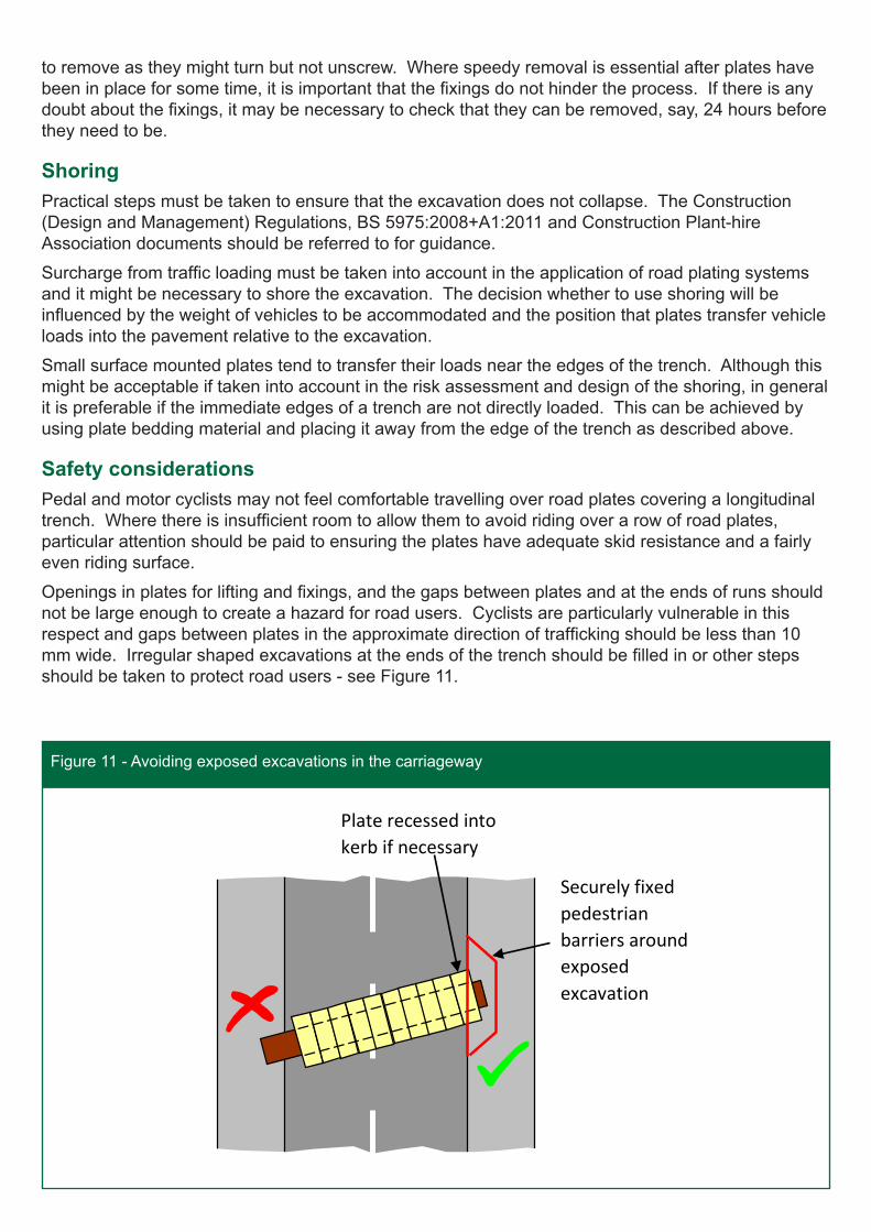
Openings in plates for lifting and fixings, and the gaps between plates and at the ends of runs should not be large enough to create a hazard for road users. Cyclists are particularly vulnerable in this respect and gaps between plates in the approximate direction of trafficking should be less than 10 mm wide. Irregular shaped excavations at the ends of the trench should be filled in or other steps should be taken to protect road users - see Figure 11.
Figure 11 - Avoiding exposed excavations in the carriageway
Plate recessed into kerb if necessary
Securely fixed pedestrian barriers around exposed excavation
Figure 11 - Avoiding exposed excavations in the carriageway
The skid resistance of plates should ideally match that of the road surface, although this may be difficult to achieve in practice. The need for adequate skid resistance is probably greatest on longitudinal runs in the wheel paths of vehicles. In particular, where the wheels on one side of a vehicle only pass over road plates, care is required to ensure that the skid resistance of the plates is not significantly different from that of the adjoining road surface. Otherwise, there might be a risk of vehicles slewing under heavy braking.
A skid resistance value of at least 45 (as measured by the British Pendulum portable skid resistance tester) is recommended on low speed roads. Higher skid resistance may be required at locations where traffic may have to slow down or change direction, such as junctions and pedestrian crossings.
Noise levelsNoise can be generated by road plates when vehicles cross them. Vehicle induced noise is likely where plates:
• are unevenly supported allowing them to rock when trafficked;
• can bounce off their seatings when trafficked; or
• can deform under loading allowing them to impact the road or recess surface.
Problems of uneven support are less likely where plates are placed on bedding material, and plates are less likely to bounce off their seatings when properly fixed. Heavier plates, especially those that are recessed, are less prone to this but fixings are always required to restrict movement. The causes of excessive rocking or noise should always be investigated. Once a plate starts to move, the bedding material may deform unevenly or be damaged. It may therefore be necessary to replace the bedding material from time to time. Additional fixings may also be required.
During installation, recessed plates tend to result in more noise than surface mounted plates because of the saw cutting and planing operations. However, vehicles are less likely to generate noise when plates are fully recessed, and this also improves the stability of plates and enables them to be crossed at higher speeds. Recessed plates may therefore be the preferred solution, particularly in environments where minimising noise is important.
Traffic speedIdeally, road users should be able to cross plates without braking. High speed impacts on plates and excessive braking can overload fixings and may cause the plates to become displaced. Traffic should not be allowed to cross road plates at speeds above those recommended by the manufacturers. Where this is a problem, it may be necessary to implement measures such as temporary speed limits, additional signing, or temporary speed humps. If excessive speeds continue (or are anticipated) to be a problem, it may be necessary to use arrangements that can better accommodate them, such as fully recessed plates. Anticipated traffic speed must form part of the risk assessment prior to the use of road plates.
Inspection and maintenanceRoad plates should be regularly monitored to ensure they are performing as intended and being crossed safely. An inspection and maintenance regime should be considered with the first inspection taking place typically within the first hour of trafficking. The frequency of subsequent inspections should be in accordance with the manufacturer’s recommendations or the site risk assessment. The required frequency of inspections (or remedial works) will vary depending on the inherent resilience of the installation and the type and level of traffic being accommodated. Anti-skid coatings should be replaced when the skid resistance falls below an acceptable value. Damaged plates that cannot be repaired should be discarded.
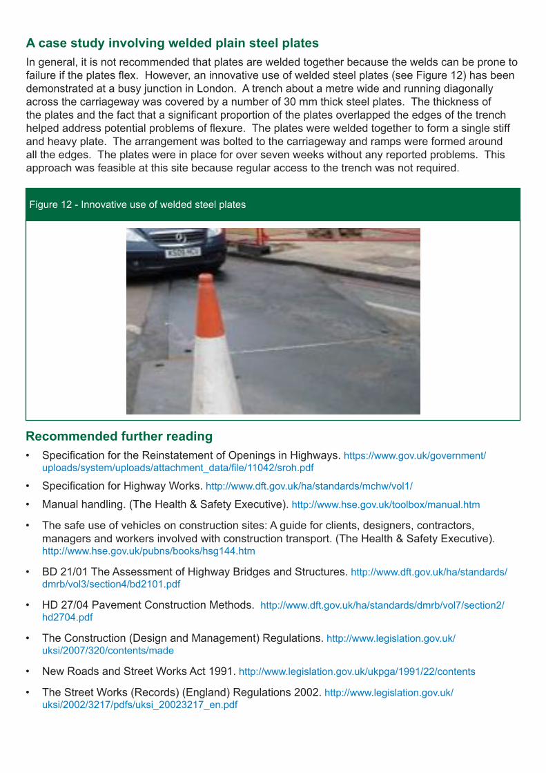
Figure 12 - Innovative use of welded steel plates
Recommended further reading• Specification for the Reinstatement of Openings in Highways. https://www.gov.uk/government/
uploads/system/uploads/attachment_data/file/11042/sroh.pdf
• Specification for Highway Works. http://www.dft.gov.uk/ha/standards/mchw/vol1/
• Manual handling. (The Health & Safety Executive). http://www.hse.gov.uk/toolbox/manual.htm
• The safe use of vehicles on construction sites: A guide for clients, designers, contractors, managers and workers involved with construction transport. (The Health & Safety Executive). http://www.hse.gov.uk/pubns/books/hsg144.htm
• BD 21/01 The Assessment of Highway Bridges and Structures. http://www.dft.gov.uk/ha/standards/dmrb/vol3/section4/bd2101.pdf
• HD 27/04 Pavement Construction Methods. http://www.dft.gov.uk/ha/standards/dmrb/vol7/section2/hd2704.pdf
• The Construction (Design and Management) Regulations. http://www.legislation.gov.uk/uksi/2007/320/contents/made
• New Roads and Street Works Act 1991. http://www.legislation.gov.uk/ukpga/1991/22/contents
• The Street Works (Records) (England) Regulations 2002. http://www.legislation.gov.uk/uksi/2002/3217/pdfs/uksi_20023217_en.pdf
A case study involving welded plain steel platesIn general, it is not recommended that plates are welded together because the welds can be prone to failure if the plates flex. However, an innovative use of welded steel plates (see Figure 12) has been demonstrated at a busy junction in London. A trench about a metre wide and running diagonally across the carriageway was covered by a number of 30 mm thick steel plates. The thickness of the plates and the fact that a significant proportion of the plates overlapped the edges of the trench helped address potential problems of flexure. The plates were welded together to form a single stiff and heavy plate. The arrangement was bolted to the carriageway and ramps were formed around all the edges. The plates were in place for over seven weeks without any reported problems. This approach was feasible at this site because regular access to the trench was not required.
Published by the Department for Transport © Crown copyright 2014.
The DfT sponsors a wide range of research into traffic management issues. The results published in these Traffic Advisory Leaflets are applicable to England and Wales, subject to variations in statutory provisions or administrative practices between the countries. Within England, enquiries should be made to: Traffic Division, Department for Transport, 3/26 Great Minster House, 33 Horseferry Road, London, SW1P 4DR. Telephone 020 7944 2974. E-mail: [email protected]
To join the publications mailing list, send an e-mail with the subject “subscribe” to [email protected]
• The Construction Plant-hire Association publications. http://www.cpa.uk.net/publications/
• BS 5975:2008+A1:2011 Code of practice for temporary works procedures and the permissible stress design of falsework. http://shop.bsigroup.com/ProductDetail/?pid=000000000030240690
• BS 5228-1:2009+A1:2014 Code of practice for noise and vibration control on construction and open sites. http://shop.bsigroup.com/ProductDetail/?pid=000000000030258086
Contact detailsTraffic DivisionDepartment for Transport3/27 Great Minster House33 Horseferry RoadLondonSW1P 4DRTel: 020 7944 2974 E-mail: [email protected]/dft
The Construction Plant-hire Association27/28 Newbury StreetLondonEC1A 7HUTel: 020 7796 3366Email: [email protected]://www.cpa.uk.net/home/
Health and Safety Executivehttp://www.hse.gov.uk/contact/