Embed Size (px)
Citation preview
[DOE LETTERHEAD]
November 30, 1995
The Honorable John T. Conway Chairman Defense Nuclear Facilities Safety Board 625 Indiana Avenue, N.W. Suite 700 Washington, D.C. 20004
Dear Mr. Conway:
Enclosed is the "UF6 Cylinder Program System Requirements Document" dated November 1995. This document represents the first deliverable due to you as detailed in Secretary O'Leary's October 16, 1995, Implementation Plan for Defense Nuclear Facilities Safety Board Recommendation 95-1. The system requirements document will be used in the decision-making process to determine the necessary cylinder management program activities. This document specifies the requirements for the program during its current storage phase and is the initial segment of the Depleted UF6 Systems Engineering Approach that will demonstrate that the program complies with applicable standards.
This document is unclassified and is suitable for placement in the public reading room.
Sincerely,
Ray A. Hunter, Deputy Director Office of Nuclear Energy, Science and Technology
Enclosure
LO CKHRRD MARTIN/K/TSO-001, Rev. 1
UF6 Cylinder ProgramSystem Requirements Document
November 1995
EM and Enrichment FacilitiesTechnical Support Organization

K/TSO-001, Rev. 1
UF6 Cylinder ProgramSystem Requirements Document (SRD)
EM and Enrichment FacilitiesTechnical Support Organization
November 1995
Prepared byOak Ridge K-25 Site
Oak Ridge, Tennessee 37831-7603operated by
Lockheed Martin Energy Systems, Inc.for the
U. S. Department of Energyunder contract
No. DE-AC05-840R21400

—
UF6 Cylinder Program SRDTABLE OF CONTENTS
EXECUTIVE SUMMARY . . . . . . . . . . . . . . . . . . . . . . . . . . . . . . . . . . . . . . . . . . . . . . . . . . . . . . . . . . . . . . . . . . . . 1
1. SCOPE . . . . . . . . . . . . . . . . . . . . . . . . . . . . . . . . . . . . . . . . . . . . . . . . . . . . . . . . . . . . . . . . . . . . . . . . . . . . . 31.1 Purpose . . . . . . . . . . . . . . . . . . . . . . . . . . . . . . . . . . . . . . . . . . . . . . . . . . . . . . . . . . . . . . . . . . ...31.2 System Overview . . . . . . . . . . . . . . . . . . . . . . . . . . . . . . . . . . . . . . . . . . . . . . . . . . . . . . . . . . . . . . 3
1.2.I Mission . . . . . . . . . . . . . . . . . . . . . . . . . . . . . . . . . . . . . . . . . . . . . . . . . . . . . . . . . . . . . . 31.2.2 Background . . . . . . . . . . . . . . . . . . . . . . . . . . . . . . . . . . . . . . . . . . . . . . . . . . . . . . . . ...4
1.3 Organization and Description. . . . . . . . . . . . . . . . . . . . . . . . . . . . . . . . . . . . . . . . . . . . . . . . . . . . 51.3.1 Development . . . . . . . . . . . . . . . . . . . . . . . . . . . . . . . . . . . . . . . . . . . . . . . . . . . . . . . . . . 51.3.2 Requirements Structure . . . . . . . . . . . . . . . . . . . . . . . . . . . . . . . . . . . . . . . . . . . . . . . . . . 7
2. APPLICABLE DOCUMENTS . . . . . . . . . . . . . . . . . . . . . . . . . . . . . . . . . . . . . . . . . . . . . . . . . . . . . . . . . . 72.1 Governin preference s....... . . . . . . . . . . . . . . . . . . . . . . . . . . . . . . . . . . . . . . . . . . . . . . . . . . . 72.2 Guidance Reference . . . . . . . . . . . . . . . . . . . . . . . . . . . . . . . . . . . . . . . . . . . . . . . . . . . . . . . . . . . . 8
3. SITUATION ANALYSIS . . . . . . . . . . . . . . . . . . . . . . . . . . . . . . . . . . . . . . . . . . . . . . . . . . . . . . . . . . . . . . 93.1 Program Status . . . . . . . . . . . . . . . . . . . . . . . . . . . . . . . . . . . . . . . . . . . . . . . . . . . . . . . . . . . . . . . . 93.2 Interface with Subsequent Phases . . . . . . . . . . . . . . . . . . . . . . . . . . . . . . . . . . . . . . . . . . . . . . . . 143.3 Baseline Considerations mdAssumptions . . . . . . . . . . . . . . . . . . . . . . . . . . . . . . . . . . . . . . . . . 153.4 Definition ofMajor Objectives. . . . . . . . . . . . . . . . . . . . . . . . . . . . . . . . . . . . . . . . . . . . . . . . . . 18
3.4.1 Ensure Risks to Personnel, tie Public, and the Environmentare Low . . . . . . . . . . . . . 183.4.2 Mitigate Deterioration ofCylinders . . . . . . . . . . . . . . . . . . . . . . . . . . . . . . . . . . . . . . . 193.4.3 Improve Procedures and Training . . . . . . . . . . . . . . . . . . . . . . . . . . . . . . . . . . . . . . . . . 193.4.4 Evaluate and Monitor Contairunent Integrity ofCylinders . . . . . . . . . . . . . . . . . . . . . . 19
4. FUNCTIONAL ANALYSIS . . . . . . . . . . . . . . . . . . . . . . . . . . . . . . . . . . . . . . . . . . . . . . . . . . . . . . . . . . . 194.1 Functional Analysis Process. . . . . . . . . . . . . . . . . . . . . . . . . . . . . . . . . . . . . . . . . . . . . . . . . . . 194.2 System Definition . . . . . . . . . . . . . . . . . . . . . . . . . . . . . . . . . . . . . . . . . . . . . . . . . . . . . . . . . . . ,20
4.2.1 System Functions . . . . . . . . . . . . . . . . . . . . . . . . . . . . . . . . . . . . . . . . . . . . . . . . . . ...244.2.2 System Components . . . . . . . . . . . . . . . . . . . . . . . . . . . . . . . . . . . . . . . . . . . . . . . . ...244.2.3 System Activities . . . . . . . . . . . . . . . . . . . . . . . . . . . . . . . . . . . . . . . . . . . . . . . . . . . . . . 28
4.3 Functional Relationships . . . . . . . . . . . . . . . . . . . . . . . . . . . . . . . . . . . . . . . . . . . . . . . . . . . . . . 294.4 Functions Crosswalk with Major Objectives . . . . . . . . . . . . . . . . . . . . . . . . . . . . . . . . . . . . . . . . 31
5. REQUIREMENTS TOACHIEVE MAJOR OBJECTIVES . . . . . . . . . . . . . . . . . . . . . . . . . . . . . . . . . . . 325.1 Requirements toEnsure Low Risks . . . . . . . . . . . . . . . . . . . . . . . . . . . . . . . . . . . . . . . . . . . . . . . 35
5.1.1 Define the Safety Envelope . . . . . . . . . . . . . . . . . . . . . . . . . . . . . . . . . . . . . . . . . . . . . . 355.1.1.1 Description and Rationale . . . . . . . . . . . . . . . . . . . . . . . . . . . . . . . . . . . . . . . 355.1.1.2 Requirements and Intent . . . . . . . . . . . . . . . . . . . . . . . . . . . . . . . . . . . . . . . . . 35
5.1.2 Monitoring for Safety . . . . . . . . . . . . . . . . . . . . . . . . . . . . . . . . . . . . . . . . . . . . . . . . . . 365.1.2.1 Description and Rationale, . . . . . . . . . . . . . . . . . . . . . . . . . . . . . . . . . . . . . . 365.I.2.2 Requirements and Intent . . . . . . . . . . . . . . . . . . . . . . . . . . . . . . . . . . . . . . . . 36
5.1.3 Maintain Accountability and Security . . . . . . . . . . . . . . . . . . . . . . . . . . . . . . . . . . . . . . 365.1.3.1 Description and Rationale . . . . . . . . . . . . . . . . . . . . . . . . . . . . . . . . . . . . . . . 365.1.3.2 Requirements and Intent . . . . . . . . . . . . . . . . . . . . . . . . . . . . . . . . . . . . . . . . 37
5.2 Requirements to Mitigate Deterioration ofCylinders . . . . . . . . . . . . . . . . . . . . . . . . . . . . . . . . . 37
5.2.1
5.2.2
5.2.3
5.2.4
Minimize Time-of-Wetness (TOW).... . . . . . . . . . . . . . . . . . . . . . . . . . . . . . . . . . . . 375.2.1.1 Description and Rationale . . . . . . . . . . . . . . . . . . . . . . . . . . . . . . . . . . . . . . . . 375.2.1.2 Requirements and Intent . . . . . . . . . . . . . . . . . . . . . . . . . . . . . . . . . . . . . . . . 38Maintain Valve andPlugIntegrity . . . . . . . . . . . . . . . . . . . . . . . . . . . . . . . . . . . . . ...385.2.2.1 Description and Rationale . . . . . . . . . . . . . . . . . . . . . . . . . . . . . . . . . . . . . . . 395.2.2.2 Requirements and Intent . . . . . . . . . . . . . . . . . . . . . . . . . . . . . . . . . . . . . . ...39Minimize Handling Damage... . . . . . . . . . . . . . . . . . . . . . . . . . . . . . . . . . . . . . . . ...395.2.3.1 Description and Rationale . . . . . . . . . . . . . . . . . . . . . . . . . . . . . . . . . . . . . . . . 395.2.3.2 Requirements and [ntent . . . . . . . . . . . . . . . . . . . . . . . . . . . . . . . . . . . . . . ...40Manage Non-Conforming Cylinders . . . . . . . . . . . . . . . . . . . . . . . . . . . . . . . . . . . . . . . 405.2.4.1 Description and Rationale . . . . . . . . . . . . . . . . . . . . . . . . . . . . . . . . . . . . . . . . 405.2.4.2 Requirements and Intent . . . . . . . . . . . . . . . . . . . . . . . . . . . . . . . . . . . . . . . . . 41
5.3 Requirements to Improve Procedures and Training . . . . . . . . . . . . . . . . . . . . . . . . . . . . . . . . . . 415.3.1 Periodically Assess and Update Procedures . . . . . . . . . . . . . . . . . . . . . . . . . . . . . . . 41
5.3.1.1 Description and Rationale . . . . . . . . . . . . . . . . . . . . . . . . . . . . . . . . . . . . . ...415.3.1.2 Requirements and Intent . . . . . . . . . . . . . . . . . . . . . . . . . . . . . . . . . . . . . . ...42
5.3.2 Train to Procedures . . . . . . . . . . . . . . . . . . . . . . . . . . . . . . . . . . . . . . . . . . . . . . . . . . . 425.3.2.1 Description and Rationale . . . . . . . . . . . . . . . . . . . . . . . . . . . . . . . . . .,, . ...425.3.2.2 Requirements andlntent . . . . . . . . . . . . . . . . . . . . . . . . . . . . . . . . . . . . . . ...42
5.3.3 Monitor and Assess Performance . . . . . . . . . . . . . . . . . . . . . . . . . . . . . . . . . . . . . . . . . 435.3.3.1 Description and Rationale . . . . . . . . . . . . . . . . . . . . . . . . . . . . . . . . . . . . . ...435.3.3.2 Requirements and Intent . . . . . . . . . . . . . . . . . . . . . . . . . . . . . . . . . . . . . . ...43
5.4 Requirements to Evaluate and Monitor Containment Integrity . . . . . . . . . . . . . . . . . . . . . . . . . . 435.4.1 Define Cylinder Integrity and Storage Condition Requirements . . . . . . . . . . . . . . . . . 43
5.4.1.1 Description and Rationale . . . . . . . . . . . . . . . . . . . . . . . . . . . . . . . . . . . . . ...445.4.1.2 Requirements and Intent . . . . . . . . . . . . . . . . . . . . . . . . . . . . . . . . . . . . . . ...45
5.4.2 ldenti~and Monitor Degradation and Degradation Factors . . . . . . . . . . . . . . . . . . . . 455.4.2.1 Description and Rationale . . . . . . . . . . . . . . . . . . . . . . . . . . . . . . . . . . . . . ...455.4.2.2 Requirements and Intent . . . . . . . . . . . . . . . . . . . . . . . . . . . . . . . . . . . . . . ...46
5.4.3 Categorize and Identify Trends in Integrity . . . . . . . . . . . . . . . . . . . . . . . . . . . . . . . . . 465.4.3.1 Description and Rationale . . . . . . . . . . . . . . . . . . . . . . . . . . . . . . . . . . . . . . . . 475.4.3.2 Requirements andlntent . . . . . . . . . . . . . . . . . . . . . . . . . . . . . . . . . . . . . . ...47
6. NEXT STEPS . . . . . . . . . . . . . . . . . . . . . . . . . . . . . . . . . . . . . . . . . . . . . . . . . . . . . . . . . . . . . . . . . . . ...47
LIST OF REFERENCES . . . . . . . . . . . . . . . . . . . . . . . . . . . . . . . . . . . . . . . . . . . . . . . . . . . . . . . . . . . . . . 48
APPENDIX A . . . . . . . . . . . . . . . . . . . . . . . . . . . . . . . . . . . . . . . . . . . . . . . . . . . . . . . . . . . . . . . . . . . ...49
EXECUTIVE SUMMARY
The Department of Energy manages an inventory of uranium hexafluoride through the DepletedUranium Hexafluoride Cylinder Program; the program mission is continued safe storage of theuranium hexafluoride inventory until its ultimate disposition. Lockheed Martin Energy Systems,Inc., the managing contractor, is applying systems engineering principles to the cylinder programto strengthen and integrate program activities. This System Requirements Document is the first offour documents to be developed in the application of systems engineering principles to the program.It contains the requirements necessary to achieve the program mission and illustrates the rationaleand intent of the requirements and the applicable standards.
This document will be used in the decision-making process to determine necessary programactivities for compliance with the stated requirements. The decision-making process will bedocumented in the Systems Engineering Management Planj the next in the series of documentsassociated with the application of systems engineering principles to the program. The requirementsand rationale herein will be updated as the program generates new information and the standardsgoverning the program change. Once the Systems Engineering Management Plan is completed, itwill drive revisions to the System Requirements Document.
This System Requirements Document specifies the requirements for the program during the current,storage phase of the program, and it provides the initial segment of the flow-down process, todemonstrate that the program complies with applicable standards. The requirements apply to bothtechnical and management aspects of the program. During development of the requirements,consideration was given to maintaining the flexibility in subsequent phases of the program, whichinclude dispositioning of the depleted uranium hexafluoride and decommissioning the facilities andequipment.
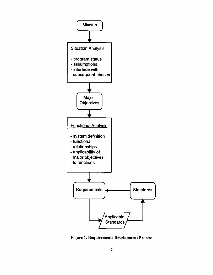
The requirements were identified through the following steps as illustrated in Figure 1.
● Conduct Situation Analysis: Major objectives for the program were developed by articulating thecurrent configuration of the program, reviewing the situation to determine focus areas that arenecessary to meet the mission, and delineating and veri~ing baseline considerations andassumptions.
● Define System Functions: The program was defined in terms of components and activities forvarious operational states, (e.g., routine and off-normal), which are described in four system
functions. These four system fimctions are:(l) surveillance and maintenance, including maintenancecoating; (2) handling and stacking; (3) transfer of UF6 contents; and (4) off-site transport. The keyrelationships between these functions were also specified.
● Determine Requirements: The system functions were compared to the major objectives todetermine the technical and management requirements for successfully meeting the programmission. To complete this functional analysis, the standards (applicable Department Of EnergyOrders, federal regulations, industry codes, etc.) that govern the requirements were identified.Deviations from applicable standards are fully addressed, to ensure safe operation. An iterativeprocess of reviewing the requirements for applicable standards and reviewing potential standardsfor necessary requirements established the quality and comprehensiveness of the requirementsidentified herein.
1
- program status- assumptions- interface with
subsequent phases
fMajor
\
Objectives
\ J
ional A@@s
- system definition- functional
relationships- applicability of
major objectivesto functions
f \ f \
Requirements 4 Standards
\ ) JA
Figure 1. Requirements Development Process
2
1. SCOPE
The following section describes the application of systems engineering principles to the storagephase of the UF6 Cylinder Program. In particular, this defines the development and application ofsystems requirements.
1.1 Purpose
This System Requirements Document (SRD) illustrates the process of determiningg the requirementsfor the uranium hexafluoride (UF6) Cylinder Program during the storage phase. The requirements
are in part defined in applicable legislation regulations, orders, directives, codes, and standards. T’heSRD provides the initial segment of the flow-down process to ultimately demonstrate programcompliance with applicable requirements. These requirements include technical and managementaspects of the program. In cases where a requirement has no governing refkrence, the requirementis derived in support of the program mission. IrI the development of the storage phase requirements,consideration was given to maintaining the flexibility in subsequent phases of the program(dispositioning of uranium hexa.fluoride (UF6) and decommissioning of existing facilities andequipment).
T’he requirements define the basis for actions necessary to achieve the program mission. Therefore,the SRD is integral to the conf@ration by which the program is controlled. Management to theSRI) (flow-down to implementing activities) is accomplished through the Systems Engineering
Management Plan (SEMP). The SEMP will incorporate a requirements analysis that provides thedecision-making rationale for developing activities. Thus, these activities by derivation willdemonstrate compliance with applicable codes and standards. This decision-making fimction wiIlenable the integration of various aspects of the program and will define activities consistent with theprogram mission. The utility of the SEMP largely depends on the quality and thoroughness of thisSRD. The activities are camied out through the overall Program Management Plan (PMP).Necessary development actions before implementation are managed through the EngineeringDevelopment Plan (EDP). Actions within the EDP and PMP generate new information, expertise,and experience. This information is iterative feedback into the SEMP integrated decision-makingprocess for producing and improving requirements.
1.2 System Overview
1.2.1 Mission
The UF6 Cylinder Program mission is to safely store the existing DOE-owned UF6 inventorymanaged at the Oak Ridge K-25 Site, and the Paducah (PGDP) and Portsmouth (PORTS) GaseousDiffusion Plants until ultimate disposition of the UF6. The average ages of cylinders in storage atK-25, PGDP, and PORTS are 29,21, and 20 years, respectively. Much of this UF6 inventory hasbeen stored for many years without adequate surveillance and maintenance of facilities sufllcient tomeet the current program mission; therefore, comective actions are critical to the program.
3
The next phase of the program, dispositioning the UFb inventory, is under development. The finalphase, decommissioning of the facilities, will be integrated into the decontamination anddecommissioning (D&D) of the diffusion cascades at the aforementioned sites. The SRD does notencompass the requirements for these subsequent phases. However, the SRD does establish theinterface between the storage phase and these subsequent phases, including the impact onrequirements stated herein. These interfacing requirements establish continuity for the program.
1.2.2 Background
DOE has about 47,000 large-capacity cylinders containing about 555,000 metric tons of depleteduranium hexafluoride (DUFb ) in long-term storage. DUFb is generated during the operations of the
gaseous diffusion process; withdrawn from the diffision cascade as a gas; liquefied; drained intosteel cylinders, where the material solidifies at subatmospheric pressure; and then stored outdoorsin cylinder yards. Initially, DUFGwas withdrawn into 2YZ-toncylinders, but during the 1950s 10-toncylinders were used. In 1958, use of 14-ton cylinders was initiated. Most (94Yo) of the DUFCstorage cylinders have 5/1 6-inch-thick shells and are called “thin wall” cylinders; the rest have 5/8-inch-thick shells and are called “thick wall.” The thin wall cylinders were designed as economicalstorage containers that meet the pressure and temperature conditions required during liquefaction.
After a significant inventory was produced, outdoor storage facilities evolved independently at thesites. Cylinder yards are constructed of either concrete or compacted gravel, and cylinders arestacked in two-tiered rows on wooden or concrete saddles. The handling equipment used to stackthese cylinders in double-tiered rows has also evolved, from mobile cranes to specially designedtractors that grasp and lift the cylinders with hydraulically actuated tines.
Until 1990, surveillance consisted of an annual nuclear materials inventory of the cylinders. TheK-25 cylinder yards were surveyed in May 1990 to provide input for planning long-term corrosionmonitoring of cylinders. Cylinder valves with corrosion and evidence of potential valve leakagewere discovered. A subsequent valve survey in June 1990 at PORTS revealed two cylinders withbreached side walls. Investigation of these cylinder breaches determined that the causes weremechanical tears caused by impact from adjacent cylinder lifiing lugs. 1 Subsequent inspections ofstored DUFb cylinders revealed four breached cylinders at K-25. Two breaches were attributed tohandling damage, and two were most likely initiated by external corrosion resulting fromsubstandard storage conditions. 2 Another breached cylinder resulting from handling damage wasdiscovered at PGDP.
The risk to personnel health and safety, and the potential environmental impact posed by thesecylinder breaches and valve leaks, are low by nature of the system. The UFb inventory is stored asa solid. Reaction deposits formed when UFb is exposed to the atmosphere in the presence of the mildsteel containers have a self-sealing nature. The uranium is depleted in the fissionable isotope of theUFb to the point that the hazard is mostly chemotoxic, not radiological. These factors contribute tothe low risk incurred from these and potential additional failures. This low risk was confirmed byanalysis of the air and soil samples collected near the breaches at PORTS and by subsequent
4
weighing of the cylinders. Although the risk posed by these breaches is low, the existence ofbreached cylinders heightened the importance of a comprehensive, long-term, three-site cylindermanagement program.
In 1992 a cylinder integrity management plan was developed to address concerns within the storageyards and to establish the initial premise of the program today. 3 To establish more rigor within theprogram and further ensure that the inventory is stored safely, a systems engineering approach isbeing adopted. The quantity of DUF, primarily drives the scope of the program managed by DOE.However, the program also encompasses the DOE-owned natural assay and low-enriched (<5% ‘3W)UFb inventories stored at these sites.
1.3 Organization and Description
1.3.1 Development
The storage phase is ongoing, and the development and implementation of systems engineering willrun concurrent with the existing activities. Aspects of the current program will be evaluated froma systems engineering perspective and modified as the evaluation dictates.
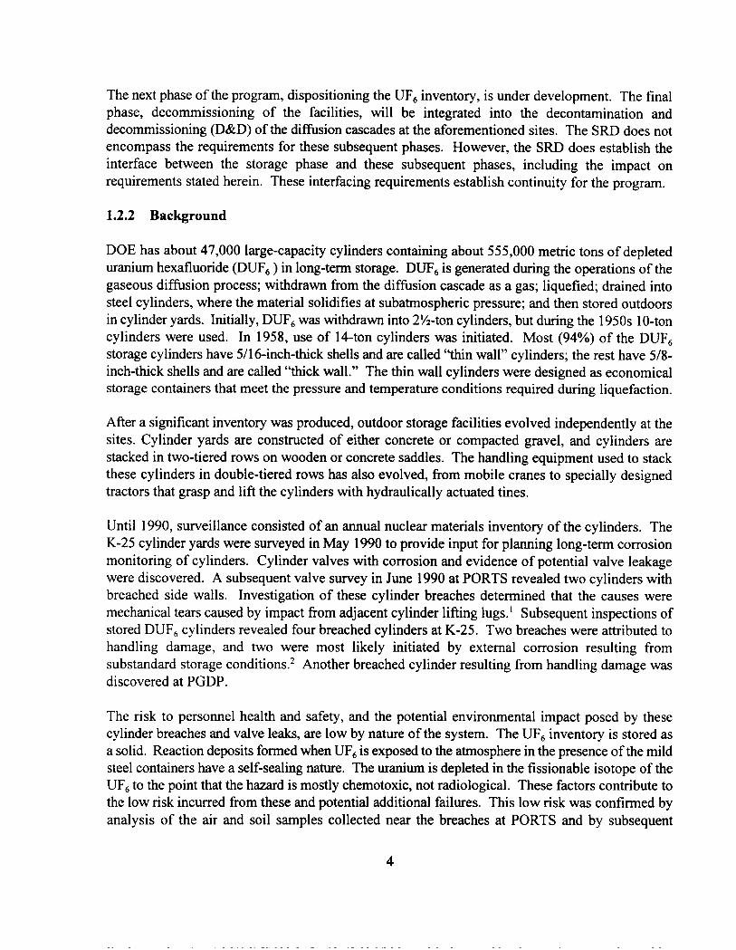
The development of the SRD necessitated an analysis of the current program (system) functions andthe current situation (cordiguration) of the program. This analysis is graphically depicted in Fig. 2.In preparation for functional analysis, the current configuration of the program was articulated in asituation analysis. Major objectives for the program were developed from the situation analysis inkeeping with the program mission. In support of the major objectives, the program was boundedby delineating and veri~ing baseline considerations and assumptions. To initiate the functionalanalysis, the functions of the storage phase (surveillance and maintenance (S&M), handling andstacking, contents transfer, and off-site transport) were defined in terms of respective componentsand activities. These components and activities include hardware, personnel, command media ordocumentation, support functions, program activities, and interfaces with organizations regulatingand performing the activities. The components and activities for each function were identified forrelevant operational states including start-up, shutdown, routine, and off-normal. The interrelationsamong these functions were delineated, and the interface of the current phase of the program(storage) with subsequent phases was evaluated. This later evaluation was performed to ensureflexibility and success in the dispositioning and decommissioning phases of the program. Tocomplete the functional analysis and determine the technical and management requirements forsuccessfully executing the program mission, the defined system functions were evaluated in thecontext of the major objectives. In many cases requirements are grouped into categories facilitatingthe rationale and intent of the requirements. Where applicable DOE Orders, regulations, industrycodes, and standards govern these requirements, they are referenced. Deviations from applicablestandards are fully identified, to ensure safe operations.
This process reflects the adaptation of systems engineering into an existing program, where many
activities within the program are defined and underway.
5
Mission:
Maior
Functions:
DWG. NO. WG.95.2MWCI
Safely store the existingDOE-owned UF6 inventory until ultimate disposition
I
EnsureLowRisk
1I 1uMitigate
Deteriorationof Cylinders
1
ImproveProceduresand Training
rEvaluateand MonitorContainment
U!2LAnalyze Current Program Situation
Identify Baseline Assumptions
IL~Surveillance Handling
and andContents Offsite
Maintenance StackingTransfer Transport
Define System Components and Activities J
1 I I IComponents Components Components Components
and and and andActivities Activities Activities Activities
1
Analyze to Determine System Requirements
I System Requirements
Figure 2. Development of System Requirements
6
1.3.2 Requirements Structure
The requirements are documented where specific rationale logically dictates the need for arequirement. The purpose for listing requirements immediately following the rationale is to clearlyshow the development and intent of each system requirement and facilitate its application in theSEMP. Applicable standards and governing documents for specified requirements are identified in[brackets] following each requirement. The [brackets] are the means for locating requirements inthe body of this document. Where a requirement, as specified by [lv-acke[s], does not have anapplicable standard or governing document, the standard is considered to be managed within theprogram. These standards are denoted in the text by [Derivedl. Requirements identified in theSituation Analysis are repeated in the Functional Analysis.
2. APPLICABLE DOCUMENTS
As effected by Requirements Change Notice Number 0R35 to Contract NumberDE-AC05-840R2 1400, dated October 1, 1995, DOE Environmental , Safety and Health (ES&H)directives were deleted and contract activities were subjected to alternative DOE approved ES&Hrequirements.
2.1 Governing References
Appendix A of this document lists the regulato~ and guidance source documents currentlycomprising this contractual ES&H basis for requirements’ identification. The list was generatedfrom the Standards Management Information System data base and includes federal and stateregulations, executive orders, DOE orders and standards. Standards and requirements are modifiedin a controlled manner under the contract’s requirements change notice process. Events that mayinitiate a change to the contract requirements include modification, addition or deletion of federaland state regulations or DOE orders and standards. As systems engineering proceeds for the UF6cylinder program, appropriate requirements will continue to be incorporated into the program SARSand procedures.
7
2.2 Guidance Reference
Essential and fundamental features of Lockheed Martin Energy Systems (LMES), Inc. environmentaland safety programs are identified and summarized in Safety Management Program Support Nuclear
and Hazardous Facilities.4 This report addresses requirement sources, scope, ancVor gradation forthe following programs:
Standards Management Criticality SafetyRadiation Protection General Environmental ProtectionIndustrial Hygiene Radioactive and Hazardous Material Waste Management
Maintenance Initial Testing and In-Service Surveillance
Conduct of Operations Fire ProtectionTraining Human FactorsQuality Assurance Emergency ManagementConfiguration Management Decontamination and DecommissioningOccurrence Reporting Safety Analysis Review and Unreviewed Safety
Question Determination
Subsequent to development of system fictional requirements in support of major objectives,specific source requirements pertinent to the UFb Cylinder Program were identified by subject matterexperts. Refinement of this initial “mapping” of source requirements to systems requirements,definition of activities and subsequent verification of compliance and adherence to standards willcontinue throughout the UF6 Cylinder Program Systems Engineering process. Results of initial“mapping” appear in Section 5, Requirements to Achieve Major Objectives. The source
requirements identified in this manner are listed below:
1.2.3.4.
5.6.7.
8.9.
10.11.12.
13.14.
10 CFR 830.120, Quality Assurance10 CFR 835, Occupational Radiation Protection29 CFR 1910, Occupational Safety and Health Standards49 CFR 173.420, Uranium Hexafluoride (Fissile and Low Spec@c Activity)
DOE 4330.4B, Maintenance Management Program MaintenanceDOE 4700.1, Project Management SystemDOE 5480. 18A, Accreditation of Performance-Based Training for Category A Reactors and
Nuclear FacilitiesDOE 5480.19, Conduct of Operations Requirements for DOE FacilitiesDOE 5480.20A, Personnel Selection, Qualljication, and Training Requirements for DOENuclear FacilitiesDOE 5480.23, Nuclear Safety Analysis ReportsDOE 5480.24, Nuclear Criticality SafetyDOE 5480.26, Trending and Analysis of Operations Information Using Performance
IndicatorsDOE 5480.28, Natural Phenomena Hazard MitigationDOE 5481.1 B, Safety Analysis and Review System
8
15.16.17.
18.19.20.21.22.
DOE 5633 .3B, Controi and Accountability of Nuclear MaterialsDOE 5700.6C, Quality AssuranceDOE 6430. 1A, General Design Criteria, including all applicable regulatory requirementsreferenced in Section 0106 and all references standards and guides in Section 0109DOEIORO-651, Rev. 6, Uranium HexaJuoride: A Manual of Good Handling PracticesAmended Consent Decree, State of Ohio (DRAFT- under negotiation)ANSI N 14.1, Uranium HexaJuoride - Packaging for TransportationASME Boiler and Pressure Vessel CodeDOE-HDBK- 1090-95, DOE Handbook - Hoisting and Rigging
3. SITUATION ANALYSIS
The following section provides the development of the program’s major objectives rationale. Themajor objectives are established to focus the management of the program on key aspects necessaryto meet the program mission. These objectives stem from an understanding ofi (1) the current statusof the program, (2) the interface of the storage phase (current phase) with subsequent phases (UFbdisposition and decommissioning of the storage facilities), and (3) the bounding assumptions for theprogram. To complete the situation analysis, the major objectives are identified and defined forapplication in the fictional analysis used to determine the necessary requirements of the system.
3.1 Program Status
The program status documents the current understanding of the condition of the program includingknown deficiencies and concerns, and actions taken to date to reduce the risks within the program.The actions stated in this section will be evaluated in the SEMP.
A number of general and specific system problems and deficiencies have been identified through selfassessments and improvements in management practices. Conditions and factors that havecontributed to the causes date back to when DOE and predecessor agencies began placing DUFG instorage. The fimdarnental cause is that a risk analysis for the UFb Cylinder Program has not beenadequately documented. Additional contributing causes include the absence of a defined life-cyclecylinder maintenance program, lack of appropriate resource application at the onset of long-termstorage, lack of adequate operational controls used to place cylinders in their current locations,inadequate integration of program operations, and absence of a well-defined mission leading to theultimate disposition of DUFb stored in cylinders.
These past general program management deficiencies have resulted in the following conditions:
1. A number of cylinders were permitted to remain for extended periods in ground contact andin storage yards where drainage was not maintained. This condition, in conjunction with nomaintenance of a protective coating, has resulted in accelerated corrosion of cylinder bodiesand the through-wall corrosion (failure) of two cylinders. The mild steel composition of thecylinders corrodes at an accelerated rate under extended periods of wetness.
9
2. Before 1990, the program did not include a cylinder inspection program, which caused thecylinders and storage conditions to deteriorate without updated characterization. This lackof characterization resulted in the unmitigated continued storage of breached cylinders andcylinders with leaky valves, use of cylinders without nameplates, and the continued use ofsafety documentation that does not reflect current cylinder conditions.
3. Handling and stacking procedures and operations before 1990, resulting in the currentstorage configuration, are the cause of stacked cylinder arrays with insufficient spacing tofacilitate inspection, configurations with less than desirable cylinder support, the impactfailure of five cylinders, and other physical damage to the cylinders and protective coatings.
Many specific deficiencies have been identified concerning the long-term storage facilities and thecylinders. This section states the deficiencies identified to date and prioritizes them relative to risks.Further characterization and evaluation of risks will revise this prioritization. Prioritizingdeficiencies will be used in the optimization of actions taken to reduce risks within the program.[Derivedl
Table 1 categorizes identified deficiencies and potential deficiencies as: (A) Direct ContainerIntegrity Concerns, (B) Storage Facility Concerns, (C) Uranium Control Issues, (D) UFb TransferIssues, or (E) Other Issues. An estimated number of cylinders impacted by each deficiency isprovided to illustrate the magnitude of these concerns. Efforts to correct many of these deficiencieshave been expelled and are underway.
Categories A, B, and C (Direct Container Integrity Concerns, Storage Facility Concerns, andUranium Control Issues) are given priority over categories D and E (UFb Transfer Issues, and OtherIssues). Categories A, B, and C have a potential to result in an undesirable occurrence while thesecylinders are being used as long-term storage vessels. A release of uranium could occur, or thehandling of mistaken uranium assays could result (i.e., DU thought to be normal or enriched and viceversa). Within the three priority categories, highest priority is given to breached cylinders,substandard facilities, and non-DU material deficiencies (Al, B 1, and C 1, respectively). Anoccurrence from these deficiencies is considered the most serious. Category D, UFb Transfer Issues,applies to the removal of the UFb from the subject containers and is relative to the subsequent UFbdispositioning phase of the program. Category E, Other Issues, is relative to best management
practices in keeping with the long-term, safe storage of UFb. Categories D and E do not impose animmediate concern on the containment integrity of storage cylinders.
The highest priority, A 1, is given to identi@ing and controlling breaches to minimize the releaseof uranium compounds and potential environmental insult or exposure. A lesser priority is givento repairing or replacing cylinders. Until final resolution can be accomplished, patched breaches areperiodically inspected and provisions are made to prevent any spread of uranium contamination fromthe cylinder.
10
Breaches can occur by either of two mechanisms: impact or external corrosion. Other failuremechanisms, such as internal corrosion, have not proven to be realistic mechanisms within the scopeof the storage program. However, fiu-ther study may be warranted. Five breaches by impact fromadj scent cylinders during stacking and two breaches by corrosion have been identified. Theinvestigation into the exact circumstances causing the breaches has provided information crucial tothe management of long-term storage cylinder integrity.
Corroded cylinders, Category A2, area product of external accelerated corrosion due to the designof the cylinder or due to its physical placement, (e.g., a skirted cylinder or cylinders in groundcontact). The estimated number of cylinders for Category A2 does not include cylinders withdegraded or absent protective coatings that atmospheric corrosion has affected. The protectivecoating is applied to provide an initial protection against rusting and it degrades with the aging ofthe cylinder or deficient cylinder handling. In addition to the protective coating, the cylinder shellthickness is designed with a minimum of 50 roils of corrosion allowance. Atmospheric corrosion(less than 1 mil per year reduction in wall thickness) is visually identified by a uniform rust-coatedsurface without scale or pits. The rate of shell thickness reduction from accelerated corrosion canvary greatly from general atmospheric corrosion rates.
Continued use of corroded cylinders will be subject to the scrutiny of the storage vessel criteria andof possible corrective actions to be developed. The criteria will determine if a corroded cylinder isunsafe for continued use. If the cylinder requires a maintenance coating, the shell surface will beprepared and a rust-protective coating will be applied. These cylinders have been in storage thelongest period of time without protective coatings and in areas not specifically designed for long-term storage. The oldest design models include the 10-ton Model T, the 14-ton Model O, and 2!4-ton del 30A cylinders. If a cylinder is unsuited for continued storage, as determined by the storagevessel criteri~ it will be placed in a queue for transfer of its contents to another cylinder via to-be-established defective cylinder feed procedures.
Without the application of a protective coating or a change in the corrosive environment, cylindersthat exhibit heavy scaling rust or pitting-type corrosion will continue to corrode at an above-normalrate, and their life expectancy will be reduced considerably from the projections based on generalatmospheric corrosion rates. Scaling rust and pitting corrosion are results of extended periods ofwetness imposed on the cylinder shell. Once initiated, the pits and scale, without propermaintenance, will continue to facilitate water retention. Extended wetness can occur on cylindersthat by design retain rainwater or on cylinders that are stored in ground contact or in poorly drainedyards. Cylinders that by design retain rainwater are cylinders with skirts and cylinders with channel-type stiffening rings. Although drain holes can be provided where water would collect, properdrainage can be obstructed by rust and foreign material or improper cylinder stacking orientation.Maintenance to ensure these drain holes stay clear is necessary.
11
Table 1. Long-term Storage Inventory Potential Deficiencies
EstimatedPotential Deficiency Number of
CylindersAffected
A Direct Container Integrity Concerns
Al Breached cylinders - cylinders with holes in the cylinder shell 7
A2 Corroded cylinders - cylinders with visible pitting and/or scaling rust 15,000
A3 Leaking valves - valves and plugs that have recurring contamination 10
B Storage Facility Concerns
B] Substandard Facilities - sinking or poorly drained load-bearing surfaces 1~,f)oo
B2 Improper Support - upper tier cylinders supported by unsound points of 3,000contact
c Uranium Control Issues
c1 Non-Depleted Material - normal and enriched material located in DU 8
storage faci Iities
C2 ID Plates - loose or detached identification plates 200
D UFb Transfer Issues
D1 Fill-Limit Consideration - cylinders without certified internal volumes or 15,000cylinders filled above the current maximum allowable limit established inORO-651
D2 Substandard Valves - valves with missing or cracked parts, Teflon tape on 3,000threads, bent stem, and/or improper engagement
D3 Plug Replacing Valves - plugs in place of valves 1,000
D4 Physically Damaged Cylinders - cylinders that do not pass the inspection 1,000
criteria established in ORO-651 for liquid transfer
D5 Cylinders Design hindrances- cylinders that will not fit into currently 140
designed autoclaves
E Other Issues
El Inaccessible Cylinder - cylinders that cannot be accessed at both heads for a 22,000visual inspection
E2 Above Internal Vacuum - cylinders with internal pressure above the ideal 1,000
vacuum conditions
12
Leaking valves and plugs, Category A3, have a potential to release small quantities of uranium.Leaks can to some extent be identified visually by recurring contamination. Leaks can be verifiedby an HF monitor andlor a radiation contamination survey. Monitoring of suspect leaks is moreeffective during the summer months, when leakage is most likely to occur. Leakage will be
contained by tightening the valve/plug or by replacing the valve/plug. To date, valves verified as
leaking have been mitigated.
Substandard facilities, Category B 1, consist of yards that permit extended periods of wetness oncylinder surfaces due to poor drainage or settling to the extent that cylinders contact the ground.Cylinders on the bottom tier under these conditions corrode at the six o’clock position at anaccelerated rate as discussed in Category A2. The corrective action is to remove these cylindersfrom substandard conditions as soon as technically feasible and either renovate the yard to meetcurrent standards or no longer use the yard as a storage facility. PGDP yards C-745-F and C-745-G,which contain about 12,000 cylinders, have been identified as substandard storage facilities. Otheryards within the three sites have been identified as having sporadic substandard conditions. In thesecases, subjected cylinders will be removed and placed in proper storage yards.
Improper support, Category B2, consists of upper-tier cylinders that are not soundly supported bythe bottom-tier cylinders because of improper placement (e.g., a narrow-stiffening-ring to narrow-stiffening-nng support or support from a lifting lug). These cylinders present a concern in the eventof an earthquake, when an improperly supported cylinder could be dislodged and fall freely for a fewinches to a new resting position. Structural analysis will determine if the subject cylinders willbecome breached from this free fall, and a safety evaluation will determine the impact from thesepossible breaches.
Non-depleted uranium, Category C 1, is defined as cylinders that contain natural and enrichedmaterial are located in the DU storage facilities. Adequate uranium control is necessary to ensurethat cylinders containing non-DU are not mistaken for cylinders containing DU and vice versa. Allsites have a Nuclear Material Control and Accountability (NMC&A) organization that requires thatthe cylinder contents, including assay, are verified by records before the cylinder is serviced orshipped off site. The NMC&A uranium control requirements for keeping cylinders with differentassays segregated will be followed. As an additional measure, subject cylinders that cannot be easilyaccessed for segregation have been identified.
Cylinders with loose, detached, or missing cylinder identification (ID) plates, Category C2, areanother uranium control issue. Identification plates become loose or detached because of corrosionfacilitated by moisture retention between the plate and the cylinder shell and by the dissimilarmetals, stainless steel plate, and the mild steel shell. Loose and detached ID plates are occurring onthe oldest cylinders in storage. American National Standards Institute (ANSI) guidelines require thatthe original fabrication documentation be in-hand before ID plates are reattached. If thedocumentation can be obtained, ID plates will be reattached; if not, tags will be fabricated andattached. As minimum requirements, the replacement tags will indicate they are replacements andwill give the cylinder identification number. Authorization to reattach tags will be documented and
13
signed by appropriate personnel. Documentation will remain in the cylinder history file as long asthe cylinder is in service.
Table 1 lists five potential defiencies in Category D that are relative only to material transferoperations and not long-term storage. These five potential defiencies are: (1) fill-limit consideration,(2) physically damaged cylinders, (3) substandard valves, (4) plug replacing valve, and (5) non-certified volumes. Transfer Issues also include the potential presence of hydrocarbon oil in thecylinder. Some cylinders were filled before use of the improved vacuum pump design, whicheliminated the source of the hydrocarbon oil. Hydrocarbons and UFb produce an exothermicreaction. Mitigation of these potential deficiencies will be addressed as necessary in the control ofthe UFb transfer operations.
Table 1 defines the two other potential defiencies relative to long-term storage. These are:relocating inaccessible cylinders so that a more thorough visual inspection can be conducted andestablishing an internal vacuum to ensure the integrity of the UFd contents. These potentialdeficiencies will be addressed accordingly through a risk-benefit cost optimization.
3.2 Interface with Subsequent Phases
No significant design and configuration changes within the program that would incrementally impactthe decommissioning of cylinders, storage facilities, and equipment are anticipated. Current plansrequire the reconstruction of substandard facilities, to mitigate unacceptable conditions. However,if regulation changes (external governing documents) or cylinder conditions necessitate aconfiguration change, the incremental impact on the decommissioning phase could be significant.Examples of this potential impact include: (1) the need for additional precautions to protect againstenvironmental exposure and (2) more prescriptive cylinder access requirements. These examplescould dictate a change in configuration such that indoor storage, single cylinder spacing, or masscylinder replacements are considered. These options would impact the decommissioning phase withthe consumption of additional real estate for storage, and the radioactive contamination of additionalmild steel (i.e., the need for new cylinders). Impact on the subsequent dispositioning and
decommissioning phases of the program will be considered when developing actions toaccommodate regulation changes under the current storage phase. [Derived
The greatest incremental impacts on the decommissioning phase from current operations includedecontamination and environmental remediation. These aspects are closely related when consideringthe current program. Support organizations provide oversight for compliance with requirements forcontamination control. Environmental remediation is impacted primarily by degree of containmentintegrity. Containment integrity is a major element within the storage phase, and the requirementsfor such are specified in Section 5.4. Environmental monitoring in the current phase will be assessedto ensure the establishment of additional actions, if any, beyond current activities that are necessaryto maintain compliance with applicable orders and regulations. Additional activities will beestablished such that environmental monitoring actions within the storage phase are balanced with
potential environmental remediation in the decommissioning phase. [Derivedl
14
Operations within the current storage phase require a significant interface with the dispositioningphase currently under development. The condition of the cylinder will greatly influence theflexibility of the dispositioning phase (i.e., normal off-site transport and normal transfer of thecontained UF~). Deteriorated cylinders limit this flexibility. The cylinder contents also have someimpact on the flexibility of the dispositioning phase. For example, the purity of the contents, themass, and the internal pressure can impact the dispositioning operations. It is expected that thecondition of a portion of the current cylinder inventory does not meet the minimum standards ofDepartment of Transportation (DOT) and ANSI for off-site transport. However, the off-sitetransport of these cylinders for dispositioning is not a requirement at”this time. As a contingency,engineering studies will evaluate the conditions of these cylinders and will propose solutions to thetransportation and transfer operational constraints. In addition, the planning for UFb dispositioningis taking into consideration the condition of cylinders and necessary actions to accomplishdisposition operations. [Deriveq
3.3 Baseline Considerations and Assumptions
The following considerations and assumptions are provided to bound the scope of systemsengineering. Many of these assumptions are current working assumptions that will be modifiedthrough improvements defined in the EDP. The current working assumptions are identified as suchto integrate the systems engineering approach with the current program.
1. Risks are managed within the current program. This assumption permits the program tocontinue planned operations concurrent with the safety analysis upgrade as authorized underthe current safety basis. Planned operations are necessary to correct substandard conditions.This assumption does not preclude the program from pursuing reduction of risks.
2. Effective risk management for handling degraded cylinders will not appreciably impact
planned costs and relocation timing. This statement assumes the degraded cylinder handlingrisks are accounted for in recent procedure improvements. Storage vessel criteria underdevelopment will not necessitate additional controls that impact cost and timing of plannedoperations. This assumption is integrated into budget planning for cylinder handlingoperations.
3. Current yard construction will result in storage surfaces with acceptable time of wetness.This assumption permits the progression of yard construction while the definition ofunacceptable/acceptable extended time of wetness is under development. Current design ofyards derived from general outdoor construction standards is thought to be acceptable.
4. Corrosion rates are variable and cylinder specljlc. This statement is substantiated by thefailure of two cylinders at the K-25 Site from external corrosion and the lack of thicknessdata obtained to date on other cylinders below 0.14 inches. This statement limits theusefulness of statistical wall thickness data when considering specific cylinders.
15
5.
6.
7.
8.
9.
10,
11.
12,
Skirt corrosion necessitates priority corrective measures. This assumption is based onlimited thickness data collected, corrosion products collected from cylinder skirts, andsubsequent projected rates of corrosion. This assumption substantiates the expeditedimplementation of cleaning and coating skirted regions prior to whole body painting.
As more data are gathered through nondestructive analyses, structural anaiyses, visualinspections, valve monitoring, and experiences with failed cylinders, the majority ofcylinders will be shown to comply with industry standarh for storage; the condition of those
cylinders that do not meet industry codes will be shown to present no imminent danger. Thisassumption permits the near term storage of the DUFb in existing cylinders instead of thealternative configurations such as replacement of cylinders, restoration of cylinder thickness,or acceleration of the DUF~ disposition phase.
Cylinders to be replaced will be accommodated with existing transfer capabilities at PGDPand PORTS. This assumes that only a small number of cylinders will need to be replaced.This statement is based on the continued working relationship with United States EnrichmentCorporation (USEC) and the known number of cylinders to be replaced.
Compliance with ANSIN14. 1 is not necessary for continued safe storage of cylinders. Theimpact of this assumption is minor within the current phase. However, the assumption limitsthe flexibility and economics of the subsequent phases because ANSI N 14.1 is applicable forshipment of cylinders. The validation of this assumption requires the evaluation,determination, and approval of storage vessel criteria and viable means to transport cylinderssubject to the standard or under a DOT exemption for foreseeable shipments. [Derived]
Cylinder contents purity is reflective of the statistical sampling and analysis completed atthe time of~lling. This assumption permits the planning and implementation of the
dispositioning phase based on statistical purity information and is sufficient for continuedstorage.
Cylinder contents rejlect the NMC&A database records. This assumption permits theshipment of cylinders in compliance with DOT requirements where a means to weighcylinders for accountability is not available.
The majority of X-745-C and K-1066-E yards are acceptable for continued use. Thisassumption permits the continued planned use of these yards while storage criteria are underdevelopment,
Cylinders with inaccessible plug ends do not require immediate priority action to verificontainment integri~. This assumption is substantiated by the verified conditions ofaccessible cylinders and by the verified conditions of the recently moved inaccessiblecylinders.
16
13. DOE will continue to regulate the inventory of DUFfi This assumption is based on therecent status of negotiations with the Ohio EPA on the regulatory jurisdiction of thisinventory and enables DOE to continue to manage the inventory.
14. DOT exemption for breached cylinder shipment will be approved. This assumption limitsthe exploration and planning of alternative means to replace failed cylinders at K-25. Theassumption also limits the pursuit of alternative cylinder containment methods for off-sitetransport.
15. Funding will be obtained to complete necessary activities as planned. This assumptionlimits the amount of contingency planning necessary to ensure the mission will besuccessfully accomplished.
16. The dispositioningphase of the DUFd inventory will be initiated in FY 2020 and progress
at a rate of 5000 cylinders/year. s The cylinders of lesser integrity will be dispositionedjirst.
This assumption is used in determining the extent of corrective actions necessary and thedegree of periodic maintenance implemented. This assumption is under review and will berevised through the programmatic environmental impact statement (PEIS).
17. The maintenance coating operation will result in cylinder coating llfe of 8 to 10 years. Thisassumption is supported by the literature reviews, solicited vendor experience, and the valueengineering study conducted by the program. This assumption will be used to size thecoating capacity at each storage site and develop the surface preparation method.
18. Requirements for the program that were not considered program specljic are maintainedand managed at the site level and are not contained in this SRD. This statement relies onthe support organizations at each site to oversee adherence to applicable requirements andstandards.
19. Risks within the program will be prioritized and actions to reduce these risks will beoptimized as practical. The statement enables the program to manage risks and riskreduction activities within the program.
17
3.4 Definition of Major Objectives
The major objectives of the storage program are promulgated from the situation analysis. Themission of the program is to safely store the existing DOE-owned UFb inventory until ultimatedisposition. Current expectations are that the cylinders will continue to be used as storage vesselsfor the UFb material and the cylinders will remain in outdoor storage, until ultimate disposition. Toachieve this mission in light of the current situation, four major program objectives have beenformulated to assist in focusing and organizing various program activities. These major programobjectives are:
1. Ensure risks to personnel, the public, and the environment are low.2. Improve procedures and training.3. Mitigate deterioration of cylinders.4. Evaluate and monitor containment integrity of cylinders.
The objectives are intended to provide the fia.rnework for a risk management strategy for Iong-termstorage of UFG in cylinders.
The following sections describe these major objectives and provide the rationale for theirestablishment.
3.4.1 Ensure Risks to Personnel, the Public, and the Environment are Low
This major objective ensures the program remains focused on a risk management strategy to identi~risks, control them, and to tier reduce them as feasible. Identified risks associated with theprogram include: (1) radiation exposure, (2) contact with surfaces contaminated with radioactivematerial, (3) exposure to toxic materials resulting from the release of UFC and/or reaction products,(4) standard industrial hazards, and (5) an environmental insult caused by the release of UF, and/orreaction products.
DUFb contained in cylinders presents a low radiation risk. Dose rates are estimated to be 2 mremper hour at a distance of 1 foot from cylinders and 0.5 rnrem per hour for persons performing generalcylinder yard work. The remaining risks associated with the UFb Cylinder Program are related tothe release of cylinder contents. Therefore, the primary focus of the program is to minimize risk bymaintaining the containment integrity of the cylinders.
As stated in the mission, the program strives for safe operations. In order to prepare for, establish,and conduct operations the associated risks to personnel, the public and the environment must bearticulated. These risks are a product of the hazards within the program and the probability they willmaterialize. After the hazards are identified and risks are evaluated, determining the initiating eventsand consequences, measures are established to lesson the likelihood of occurrence. In addition,mitigative measures are also pursued to minimize consequences. These defensive measures can bein the form of design, engineering, and/or administrative controls. A graded approach to
18
implementing defensive measures is taken to combat the severity of the risk recognizing design andengineering controls can provide greater assurance for protecting against initiating events andconsequences.
3.4.2 Mitigate Deterioration of Cylinders
This objective reflects the storage phase of the program and the primary risk associated with thisphase. Because the primary event of concern is loss of containment, a major objective to mitigatedeterioration and maintain or improve existing integrity is established. Consequences includingcriticality; personnel, the public, and the environmental exposure to UFb and reaction products;
contamination; and exposure to elevated level of radiation all have the common failure of loss ofcontainment. This objective also stems from the lack of maintenance of cylinders and storagefacilities in past years. This condition presents an elevated systemic risk to the program. Mitigatingdeterioration of the cylinders, particularly during the storage phase of the program, provides thegreatest flexibility in the subsequent dispositioning phase.
3.4.3 Improve Procedures and Training
Because the hazards within the storage phase are inherently low, the controls within the program tomanage risks are primarily administrative controls. This objective addresses the quality assuranceof these controls and their effectiveness in controlling activities that present risk.
3.4.4 Evaluate and Monitor Containment Integrity of Cylinders
This objective also focuses on the current phase of the program, storage of the UFb inventory. Thisobjective defines and maintains a status of conditions and establishes the forecasting information toensure success of the program mission. This is accomplished by monitoring and evaluating cylinderand storage conditions, in addition to monitoring factors that degrade conditions for the purposes offorecasting. The monitoring of degradation factors establishes a proactive approach to potentialsystem problems with containment integrity.
4. FUNCTIONAL ANALYSIS
4.1 Functional Analysis Process
The functional analysis derives the requirements and applicable standards from the major objectivesof the program (Fig. 2). In order to comprehensive y determine the requirements for the program,it is necessary to first identi~ the system fictional activities and components within the start-up,routine, shutdown, and off-normal states of operation for the fimdamental system roles ofsurveillance and maintenance, handling and stacking, contents transfer, and off-site transport. Thefirst task of the functional analysis was to define the system. A checklist method was used to definethe system. This checklist method used key words to elicit the components and activities within thesystem at the various operational states. The key words used include: physical equipment,
19
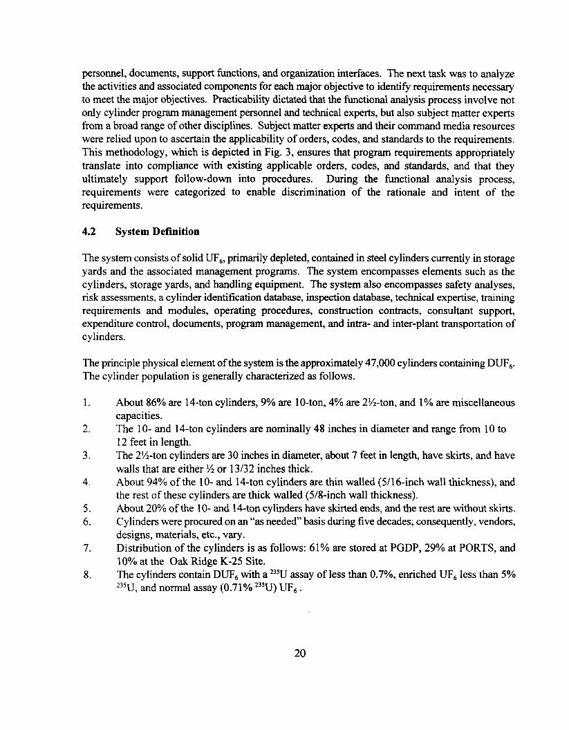
personnel, documents, support fhnctions, and organization interfaces. The next task was to analyzethe activities and associated components for each major objective to identifi requirements necessaryto meet the major objectives. Practicability dictated that the functional analysis process involve notonly cylinder program management personnel and technical experts, but also subject matter expertsfrom a broad range of other disciplines. Subject matter experts and their command media resourceswere relied upon to ascertain the applicability of orders, codes, and standards to the requirements.This methodology, which is depicted in Fig. 3, ensures that program requirements appropriatelytranslate into compliance with existing applicable orders, codes, and standards, and that theyultimately support follow-down into procedures. During the fictional analysis process,requirements were categorized to enable discrimination of the rationale and intent of therequirements.
4.2 System Definition
The system consists of solid UFb, primarily depleted, contained in steel cylinders currently in storageyards and the associated management programs. The system encompasses elements such as thecylinders, storage yards, and handling equipment. The system also encompasses safety analyses,risk assessments, a cylinder identification database, inspection database, technical expertise, trainingrequirements and modules, operating procedures, construction contracts, consultant support,expenditure control, documents, program management, and intra- and inter-plant transportation ofcylinders.
The principle physical element of the system is the approximately 47,000 cylinders containing DUFb.The cylinder population is generally characterized as follows.
1.
2.
3.
4.
5.6.
7.
8.
About 86°A are 14-ton cylinders, 9% are 10-ton, 4°A are 2%-ton, and 1‘A are miscellaneouscapacities.The 10- and 14-ton cylinders are nominally 48 inches in diameter and range from 10 to12 feet in length.The 2%-ton cylinders are 30 inches in diameter, about 7 feet in length, have skirts, and have
walls that are either % or 13/32 inches thick.About 94?40of the 10- and 14-ton cylinders are thin walled (5/16-inch wall thickness), andthe rest of these cylinders are thick walled (5/8-inch wall thickness).About 20% of the 10- and 14-ton cylinders have skirted ends, and the rest are without skirts.Cylinders were procured on an “as needed” basis during five decades; consequently, vendors,designs, materials, etc., vary.Distribution of the cylinders is as follows: 61% are stored at PGDP, 29V0 at PORTS, and10?40at the Oak Ridge K-25 Site.The cylinders contain DUF~ with a 235Uassay of less than 0.7°/0, enriched UFC less than 50/0
2351_J and normal assay (0.71°/0235U) UFb .7
20
Applicable
DOE orders
CFRs
DOE-STD
ANSI
ASME
EPA
Subject Matter
Experts
Knowledgeable onCodes, CFRS,
Standards
● Nuclear Safety
“ EmergencyResponse
. RadiationProtection
● IndustrialHygiene
● EnvironmentalCompliance
● Conduct ofOperations
● Training
● Procedures
● Operations
“ Criticality Safety
● SystemsEngineering
uMission
I Major IObjectives
TechnicalExperts
- FunctionalAnalysis
t
‘v CylinderProgram
I Management
1
programRequirements
that meetOrders, CFRs,and Standards,
as well asProgram Needs
Figure 3. Relationship of Requirements to Orders, Codes, and Standards
21

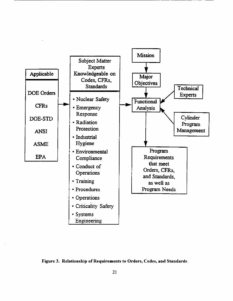
Cylinder designs have evolved over the years. Design modifications vary from lifting lug shapesand stiffening ring designs to a change in the reference grade of steel. The cylinder model types andthe number of each type that have been in semice are shown in Fig. 4.
Manufacturing standards have also changed over the years. Current manufacturing guidelines arecontained in ANSI 14.1 and are primarily directed at the original cylinder duty cycle.
Storage yards are another physical element of the system and are constructed of either concrete orcompacted gravel. Cylinders are typically double stacked on cylinder yards in straight double rows,and there is a small aisle between some double rows. Some of these aisles are currently wide enoughto allow personnel access, but most are not wide enough to allow passage of mobile equipment. Inmost cases, the cylinder heads face the aisles, to facilitate inspection and inventory control. Thebottom cylinders are positioned primarily on wood saddles, and a limited number of concrete saddlesare currently in use. The top cylinders are positioned on two bottom row cylinders. Empty cylindersor heel cylinders may be triple stacked in straight rows with a small aisle between each double row.Currently there are two yards at PORTS, ten at PGDP, and five at the K-25 Site. These yards covera combined surface area of about 3.3 million square feet.
An additional physical element of the system is the cylinder handling equipment, which has alsoevolved over the years. Originally mobile cranes and removable bands were used to stack andunstack cylinders. Current handling equipment includes the cylinder stacker, which is used forstacking and unstacking as well as for transporting cylinders short distances. The “straddle carrier”is used for in-plant transport of cylinders. An additional device used for in-plant transport ofcylinders is a specially designed trailer. Although there are slight variations in types of equipmentitems at the three sites, these are the principal pieces of hardware used to handle UFb cylinders.
22
10-Ton Cylinders
Number
Qli~jers
450(
3500
3000
2500
2000
1500
1000
500
0
25,000
20,000
Numberof 15,000
Cylinders
10,OOO
5,000
0
Thin wall, w/skirts. . . . . . . . . . . . . . . . . . . . . . . . . . . . . . . . . . . . . . . . . . . . . . . . . . . . . . . . . . . . . . . . . . . . . . . . .
4230. . . . . . . . . . . . . . . . .
. . . . . . . . . . . . . . . . . . . . . . . . . . . . . . . . . . . . . . . . . . . . . . . . . . . . . . . . . . . . . . . .
. . . . . . . . . . . . . . . . . . . . . . . . . . . . . . . . . . . . . . . . . . . . . . . . . . . . . . . . . . . . . . . .
. . . . . . . . . . . . . . . . . . . . . . . . . . . . . . . . . . . . . . . . . . . . . . . . . . . . . . . . . . . . . . . .
Thick Wall w/Skirts. . . . . . . . . . . . . . . . . . . . . . . . . . . . . . . . . . . . . . . ... . . . . . . . . . . . . . . . . . . . . . . .A
r >. . . . . . . . . . . . . . . . . . . . . . . . . . . . . . . . . . . . . . . . . . . . . 1856 ... .. . . .
.. .. . . . .. . . . . . . ..- 1365 . . .. . . . . . . . . . . . .
.. .. . . . . . . . . . . . . . . . . . . . . . . . . . . . . . . .
.. . . . . . .. . . . . . . . . . . . . . . . . . . . . . . . . ..
. . . . . . . . .
. . . . . . . . .
. . . . . . . . .
. . . . . . . . .
. . . . . . . . .
. . . . . . . . .
. . . . .
. . . . . . . . . . . . . . . . .
. . . . . . . . . . . . . . . . .
. . . . . . . . . . . . . . . . .
. . . . . . . . . . . . . . . . .
. . . . . . . . . . . . . . . . .
L . . . . . . . . . . . . . . . . .
. . . . . . . . . . . . .
. . . . . . . . ., . . . . . . . . . . . . . . . . .
48A 48X T
Cylinder Model
14-Ton Cylinders
. . . . . . . . . . . . . . . . . . . . . . . . . . . . . . . . . . . .Thin wall,Aw/oskirts
. . . . ..” . . . . . . . . . . . . . . . . . . .. C . . . . . . . . . . . . . . . . . . . . 23.8M>
. . . . . . . . . . . . . . . . . . . . . . . . . . . . . . . . . . . .
. . . . . . . . . . . . . . . . . . . . . . . . . . . . . . . . . . . .
. . . . . . . . . . . . . . . . . . . . . . . . . . . . . . . . . . . .
. . . . . . . . . . . . . . . . . . . . . . . . . . . . . . . . . . . .Thick Wall, w/Skirts
* \
. . . . . . . . . . . . . . . . . . . . . . . . . . . . . . . . . . .
. . . . . . . . . . . . . . . . . . . . . . . . . . . . . . . . . . .
. . . . . . . . . . . . . . . . . . . . . . . . . . . . . . . . . . .
r 30 60 260 ‘
OH OHI 48Y 48HX 48H o
. . .
. . .
. . .
. . .
. . . . . . . . .
OM
Cylinder Model
Figure 4. Number of Cylinders
23
Containing DUFG, by Model
,.. .
,.. .
,.. .
.. . .
—48G
4.2.1 System Functions
The four primary fictions in the storage phase of the program are, as shown in Fig. 2. (1)surveillance and maintenance, (2) handling and stacking, (3) contents transfer, and (4) off-sitetransport of cylinders. Function 1, surveillance and maintenance, includes system activities tomaintain cylinder and storage yard conditions. Function 2, handling and stacking, focuses on theon-site movement of cylinders and associated support activities. Function 3, contents transfer,addresses activities necessary to remove the cylinder contents. Function 4, off-site transport,includes the activities required to ship cylinders from the DOE facilities to other locations.Functions 1 and 2 are expected to include significant activity for the next 5 to 10 years assubstandard conditions are mitigated (e.g., cylinder storage yard reconstruction and cylinder coatingmaintenance). After this corrective actions period, these two fbnctions are expected to focus onsurveillance and maintenance activities, including maintenance of cylinder coating. Functions 3 and4 are expected to involve a minimal number of cylinders, but these fimctions are necessary to supportthe program mission of safe storage and to facilitate the development of the dispositioning phase ofthe program. The near-term level of activity within these two fimctions is dependent on thepopulation of cylinders found to be unacceptable and repairable for continued storage. Anotherimpact on the level of activity in Function 4 is the possibility of inventory consolidation from threesites to two or one.
Section 4.2.2 provides a detailed listing of components in each function. Section 4.2.3 provides adetailed listing of activities within each fi.mction.
4.2.2 System Components
The system components are categorized as physical equipment, personnel, support organizations,documentation, and organization interfaces and are shown in Lists 1 through 5. The physicalequipment and personnel are further categorized by the system timctions.
24
List 1. PHYSICAL EQUIPMENTSurveillance and Maintenance Function
UF, (including depleted,enriched, and normal)
Cylinders (includingnameplates, stiffening, rings,lifting lugs, and seam welds)
Cylinder valves and plugs
Storage facilities (includingconcrete and gravel yards,concrete saddles, yard lighting,alarms, run-off, catch basins,and fallouts)
Technical assessmentequipment, i.e., ultrasonicthickness (UT) apparatus
Inspection, monitoring, andsurvey equipment
Cylinder coatingfacility/designated area
Cylinder surface preparationequipment
Blast media
Coating equipment
Handling and Stacking Function
Coating (including paint,thinner, and cleaners)
Coating operation wastes
Yard boundary control signage
Personal protection equipment
Valve change out equipment
Decontamination equipment
Emergency patch equipment
Cylinder stand/turning fixture
Straddle buggy Full cylinder handler/stacker Communication equipment(e.g., radios)
Crane (including associated Empty cylinder handlerhoisting & rigging (H&R) Equipment certification devicesequipment) Forklift (including cylinder (load cells, etc.)
handling attachments)Trailers and tractors (including Check weight cylinderstrailer saddles)
Contents Transfer Function(in addition to handling and stacking fimction and physical equipment)
Feed and withdrawal equipment Cylinder decontamination Building crane (including(including associated safety Facility associated H&R equipment)systems)
Decontamination wastes PigtailsNew cylinders; new valves, andplug Heat source
Off-Site Transport Function(in addition to handling and stacking function and physical equipment)
Rail cars Tie-down rigging TIDs (tamper indicatingTrailers and Tractors Valve covers devices)OverPacks HP survey equipment
25
List 2. PERSONNELSurveillance and Maintenance Function
Line managemenffsupervisor
Periodic cylinder inspections
Envim. monitoring technicians
Health physics technicians
Security force
Decontamination operators
Health and safety representation
NMC&A personnel
Qualified ASME codeinspectors
Finance oftlcers
Program management
Nondestructive equipmentcertified personnel
System safety engineersChemical operators
Material handlers
Maintenance personnel
Metallurgists
Industrial hygiene technicians
Painters
Quality assurance andevaluation personnel
Emergencypreparedness/response team
Procedure writer
Training personnel
Lab technicians
Construction contractors
Engineering support personnel
Equipment testing/inspectionpersonnel
Records management personnel
Computer support personnel
Handling and Stacking Function
(in addition to surveillance and maintenance function Dersonnel)
Spotter Equipment operator Operator to set saddles
Cylinder inspector Maintenance (laborers) H&R crew
H&R representatives
Contents Transfer Function(in addition to handling and stacking function personnel)
Operator
26
Off-Site Transport Function(in addition to handling and stacking function personnel)
H&R crew Transport driver DOT certified transportationQualified inspector Transportation safety “officer”Health physics technician
List 3. SUPPORT ORGANIZATIONS
Facility SafetyEmergency PreparednessFinanceUranium Material HandlersNMC&AUtilitiesIndustrial Hygiene (IH)Health Physics (HP)Nuclear Criticality Safety
Chemical Operations Self AssessmentMaintenance EngineeringProcurement Records ManagementOperations Computer SupportSecurity Technical ServicesWaste Management Equipment Test and InspectionEnvim. Monitoring Analytical ServicesComplianceQuality Assurance
List 4. DOCUMENTATION
Recommendation 95-1Technical Report to 95-1Management plansWork PlansInspection reportsTechnical reportsTechnical logsSelf-assessment reportsDesign Drawings
(yards, saddles, fixtures,cylinders, etc. )
System Requirement Dec.Sys. Engr. Mgmt PlanEngr. Development PlanMaintenance RecordsSafety basis documentationDOT exemptionsJob performance analysisBid specificationsTechnical specifications
Program Mgmt. Plan95-1 Implementation PlanShipping manifests and
other DOT paperworkHP/lH survey reportsEnvironmental Mgmt. RecordsProceduresTraining modulesMaterials & Transfer Records
List 5. ORGANIZATION INTERFACES
Contracted services Lockheed Martin EnergyLocal, state, federal agencies SystemsDOE Lockheed Martin Utility
ServicesRegulators
27
4.2.3 System Activities
The activities specific to the program are shown in List 6, The activities are organized byfunction.
List 6. SYSTEM ACTIVITIES
Surveillance and Maintenance Function
Environmental monitoring Yard constructiordreconstruction
Security monitoring Cylinder coatinghmface preparation, etc.
Inventory accountability Valve replacement amior decon
Containment integrity monitoring Skirt cleaning/coating/drain hole drilling
Technical studies/monitoring/analy sis Yard maintenance (sweeping, lighting, mowing)
Radiation/criticality and other hazard surveysWorker trainingBoundary/access control/posting/maintenanceMaintain emergency readiness/response/drillsRecords management (UCLIM, NMC&A, procedures)Program planningFinancial accountingThickness data acquisitionInventory modelingAnalysis for safety documentOccurrence reportingSelf assessments/audits
Alarm maintenanceCylinder patchinglrepair operationsInventory accountingInspections (routine, coating quality evaluation:Data entryDesign (yard, saddles, etc.)Monitoring equipment maintenance/certiiicatioDecontaminationWaste disposalCoating touch-upValve/plug replacementID plate replacementCylinder coating maintenance
Handling and Stacking Function(in addition to surveillance and maintenance functional activities)
Cylinder inspection Saddle placementimoving
NMC&A verification and authorization Cylinder lifting, hauling, and stacking
Equipment maintenance Old saddle disposition
Operator training UT testing
HP survey H&R training
Emergency responselreadiness
Contents Transfer Function
Authorization to transfer Material control verification
Feed and withdrawal preparation Investigation activities
Cylinder inspection Transfer operation
Cylinder lifting and placement with building crane Safety systems testing monitoring
Receiving cylinder preparation and connections HP monitoring
Cylinder connections, heating Cylinder weighing
28
Off-Site Trans~ort Function
External inspection cylinder components and Cylinder weight verificationtransport equipment H&R to transport vehicleHP survey Transport authorizatiorddocumentationCylinder pressure check DOT trainingNMC&A verification/authorization DOT inspection of transport vehicleSecuring cylinder on transportation vehicleInstallation of TIDs and valve coversStenciling of “radioactive LSA” on cylinder body
4.3 Functional Relationships
The relationships between the fimctions is a key aspect to having a program of safe storage.Examples include: (1) cylinders must be handled and restacked to mitigate substandard storageconditions and reduce surveillance and maintenance risks and (2) it will be necessary to transfer thecontents of cylinders found to be non-compliant with storage vessel criteria and unrefurbishable toacceptable cylinders, also reducing surveillance and maintenance risks. Transfer of cylinder contentsmay involve off-site transport. Off-site transport may also be required to pilot or demonstrate thedisposition of the DUFb. Intra-site inventory consolidation, if found to optimize the program, wouldnecessitate off-site transport of a large number of cylinders.
The primary interrelationship of these fi.mctions is the cylinder and an integrated set of acceptancecriteria (storage vessel criteria) for cylinder condition that accommodates all fictions. There areexpected to be different criteria for each of the four system finctions: surveillance and maintenance,handling and stacking, contents transfer, and off-site transport. Existing standards such as ANSIN 14.1 andORO-651 provide detailed criteria for specific functions, respectively off-site transportand liquefaction transfer of contents. ASME Boiler and Pressure Vessel code also provides design,construction, and maintenance standards for cylinders. A significant portion of the cylinderpopulation does not meet the 1/4 inch minimum wall thickness for thin wall cylinders specified inthese standards. The relationship between fi.mctional criteria will be addressed in the developmentof an integrated set of cylinder acceptance criteria (storage vessel criteria). These storage vesselcriteria will enable the program to successfully meet its mission for the storage phase, will optimizethe use of existing containers with respect to the overall program life cycle, and will optimizeultimate disposition flexibility.
29

Compliance with these storage vessel criteria will necessitate continued maintenance andverification. Cylinders that do not currently meet the storage vessel criteria, require other systemfunctions to initiate precautionary measures, including additional inspections and possibleoperations. Examples of this scenario include:
● The mass limit on cylinder contents is not a limiting criterion for the surveillance andmaintenance function and is not verified within this fiction; however, safety precautionswithin the transfer fi.mction require that the mass content be verified, because some cylindersare above weight limits for routine heating, Heating overfilled cylinders could result inhydrostatic rupture.
● An internal vacuum is not a limiting criterion for the cylinder handling and stacking fictionand is not verified within that function. However, off-site transport standards require thatthe cylinder contents beat or below atmospheric pressure. These criteria are verified withinthe transport function, and it maybe necessary to reduce internal pressure before shipment.
The program will establish maintenance and verification activities within each fimction tocompensate for cylinders that do not meet the storage vessel criteria. These activities will ensurethe risks of processing cylinders from one fimction to another are sufficiently controlled. [Derivedl
The capacity of a fimction is determined by the rate at which it can perform its intended actions.This rate is also interrelated to other fimctions. Examples include:
● The capacity to handle and restack cylinders from substandard storage conditions couldimpact the number of cylinders that meet storage vessel criteria in out-years and thus thenumber of cylinders requiring mitigative actions.
● The capacity to transfer the contents of unacceptable cylinders impacts the duration forwhich these cylinders have to remain in the surveillance and maintenance function. Riskswith prolonged storage of unacceptable cylinders need to be balanced with the capacity toreplace or repair these cylinders.
The program will ensure fimction capacity is made available commensurate with the impact on otherfunctions< Other fictional relationships include nuclear materials accountability control,contamination control, information from technical studies, and cylinder history records management.These relationships will be identified and appropriate controls verified and/or implemented tomaintain continuity of the program. [Derived
30
4.4 Functions Crosswalk with Major Objectives
Figure 5 provides an overview of the major objectives’ applicability to the system functions. Allmajor objectives are applicable to the entire system; however, this overview identifies the emphasisareas for each major objective. The overview provides the basis for the functional analysis used todetermine program requirements.
As shown in Fig. 5, the major objective Ensure risks are low applies unilaterally across all systemfimctions. A graded approach, depending on the potential consequences and frequency, is used toevaluate specific risks within each function. The greatest risks are within the cylinder contentstransfer function where significant energy is introduced to the system.
Activities to support the major objective A4itigare deterioration are not unilaterally applied to allsystem functions. The greatest level of effort to mitigate deterioration is concentrated in the storage,and handling functions where cylinder operations are continuous. The primary actions associatedwith successfully meeting this objective include facility improvements, coating maintenance, andvalve and plug maintenance. These actions do provide benefit to the transport and transfer functionsby reducing risk and increasing program flexibility.
The Improve procedures and training major objective is similar to the first objective, ensure risksare low, and unilaterally applies to all system finctions. Procedures and training are needed to
support operations in all functions. The effectiveness of these administrative controls is a keyelement to successfi.dly meeting the program mission.
Activities necessary to meet the major objective Moni/or/evaluate conditions lie primarily in thesurveillance and maintenance function of the system. However, the criteria for which these actionsveri~ acceptable conditions consider all criteria within the system.
31
System FunctionMajor objective
surveillance and handling and contents off-sitemaintenance stacking transfer transport
ensure risks are <-------unilateral application------->low
mitigatedeterioration
improveprocedures andtrainimz
monitor/evaluateconditions
< ----emphasis area---->
< -------unilateral application------->
<emphasis area>
Figure 5. Applicability of Major Objectives to System
5. REQUIREMENTS TO ACHIEVE MAJOR OBJECTIVES
Functions
The system requirements within this document provide the framework for developing activitiesnecessary to accomplish its mission. The systems engineering approach is being appliedconcurrently with an ongoing program, and many actions are in progress. The SEMP will establishthe technical basis for program activities through an analysis of requirements contained herein andothers as they are identified.
The requirements in the following section were developed through a fictional analysis of theactivities and components identified in the system description section. These activities wereanal yzed in the context of each major objective to determine what requirements needed to beestablished to accomplish the objective. To bound the development of requirements, only thosestandards that directly affect this program and its ability to meet its mission were considered.
Categories of requirements under each major objective have been established. These categories areshown in Fig. 6. These categories are not requirements of the program. They summarize therationale for the requirements.
Requirements were reviewed to identifj applicable standards and governing documents. Thesestandards are identified in [brackets] following each requirement. Section 2 provides a listing ofstandards and governing documents for the program. Where a requirement does not have an
32
applicable standard or governing document, the standard is considered to be derived within theprogram.
The following sections relate system requirements to the major objectives described in precedingsections of this document. The motivation for the development of these requirements within majorobjectives is to respond to the need expressed by the objective and, ultimately, to determine activitiesnecessary to accomplish the objectives.
33
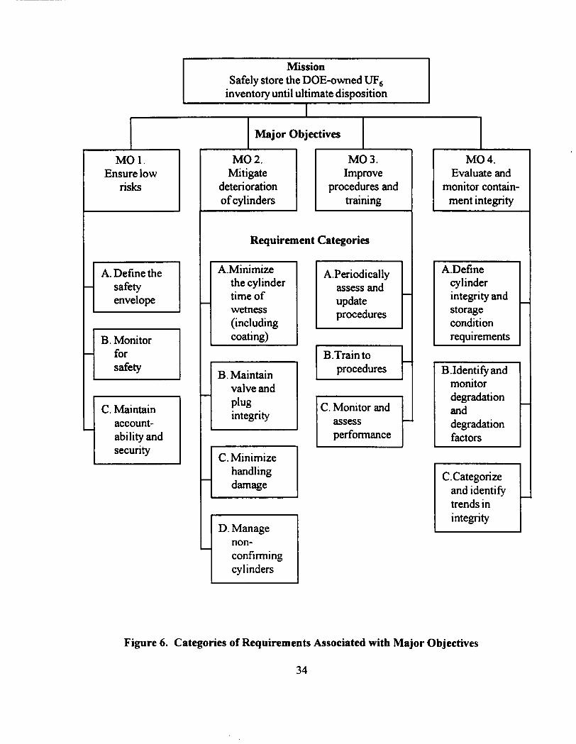
Mission
Safely store the DOE-owned UFGinventory until ultimate disposition
Ib 1 , (
MO1.Ensure low
risks
i
A. Define thesafetyenvelope
rB. Monitorforsafety
rC. Maintainaccount-ability andsecurity
&b’-&Requirement Categories
A.Minimizethe cylindertime ofwetness(including
b9!!A--
B. Maintainvalve andplugintegrity
rC. Minimizehandlingdamage
D. Managenon-confirrningcylinders
A.Periodicallyassess andupdateprocedures
C. Monitor andassessperformance
t
MO 4.Evaluate and
monitor contain-ment integrity
A.Define icylinderintegrity andstorageconditionrequirements
B.Identi&and Imonitordegradationand ‘1
3C.Categorize
and identifitrends inintegrity
Figure 6. Categories of Requirements Associated with Major Objectives
34
5.1 Requirements to Ensure Low Risks
5.1.1 Define the Safety Envelope
Major Objective (MO) 1, Requirement Category A: Define the safety envelope for the handling andstorage of UFb and consider it in all system requirements, procedures, and program elements, whichwill take into consideration all DOE orders and pertinent laws, including state and federal.
5.1.1.1 Description and Rationale
In order to ensure a safe storage program, the hazards associated with storage must be identified andevaluated for control. In addition, the minimal controls necessary to manage the risks withinplanned activities must be determined, to successfully maintain a safe program. These actions,identify and evaluate hazards and determine minimal controls, define the safety basis for theprogram. This safety basis is the bounds for safe operation of the necessary program activities. Theongoing activities and potential new activities within the program are then managed within thebounds defined by the safety basis. This requirement category defines and documents the hazardsand their associated risks and consequences for clear dissemination to the workforce and controlwithin the safety basis.
An integral fimction of the safety basis is to grade the hazards. This hazard grading facilitates cleardelineation of which hazards pose the greatest risk and where multiple controls (defense-in-depth)are required and most beneficial. The grading also establishes the basis for prioritizing riskreduction actions.
5.1.1.2 Requirements and Intent
The following requirements ensure the safety aspects of the program are defined, documented, andmaintained.
1. The hazards, risks, and minimum controls will be identified, evaluated, and documented ina complete safety analysis to define the program safety basis. [DOE 5480.23, 6430.1A,5480.22,5480.24, 5480.7A]
2. The authorized safety basis will be periodically reviewed and updated, to reflect a currentsafety analysis and definition of hazards and risks within the program. [DOE 5480.23,6430.lA ]
3. Appropriate evaluations of compliance with the safety envelope will be conducted when theauthorized safety basis is in question due to changes in procedures, work scope, and/orstorage configurations. [DOE 5480.2 1]
4. Appropriate reviews and assessments will be performed, to ensure the preparedness of newactivities and facilities, and the restart of activities as appropriate. [DOE 5480.31]
5. An industrial hygiene program will identifi and administer controls to ensure propermanagement of industrial hazards. [DOE 5480.1 B, 5480.10, 5483.1A]
35
6. Conduct of Operation principles will be applied to functions and operations within thesystem, to ensure the performance of actions accomplishes the intent.[10 CFR 830.120, DOE 5480.19]
5.1.2 Monitoring for Safety
MO 1, Requirement Category B: Monitor facilities and operations for safety.
5.1.2.1 Description and Rationale
Facilities and operations must be monitored to determine the presence of hazards and potentialinitiators. These hazards and initiators are identified in the safety analysis. This monitoring ensurescompliance with the authorized safety basis and identifies necessary ameliorative actions tomaintain compliance with the authorized safety basis.
5.1.2.2 Requirements and Intent
The following requirements are established to ensure facilities and operations are monitored forcompliance with the authorized safety basis.
1.
2.
3.
4.
5.
5.1.3
The concept of as low as reasonably achievable (ALAIU4) will be incorporated in thedevelopment and execution of system operations. ALAW will serve as a guide to the riskmanagement and reduction efforts within the program. [1OCFR 835, DOE 5480.23, 5400.5,5480.10,5480.11, 6430.lA]Facilities will be regularly surveyed for radiation and release of UFb and reaction productsto evaluate program risks. [10 CFR 835, DOE 5480.23,5400.5,5480.10, 440.1]Facility safety walk-throughs will be conducted regularly, to identi~ initiators and determineameliorative actions. [DOE 5700.6C]Any subsequently identified conditions out of compliance with the safety authorization willbe ameliorated in a manner such that risks to personnel and environment are minimized.[10 CFR 830.120,10 CFR 835, DOE 5700.6C, 5480.23]Alternative methods for investigating risks, hazards, and initiators will be evaluated.[10 CFR 830,120]
Maintain Accountability and Security
MO 1, Requirement Category C: Maintain accountability and security of the inventory
5.1.3.1 Description and Rationale
The uranium in storage is considered a “source material” as defined by the Atomic Energy Act(AEA). This designation requires accountability and security of the inventory. In order to staywithin the authorized safety basis, mass and assay must be maintained. Movement, including off-
36
site transport of cylinders containing accountable inventory, is controlled through a NMC&Aprogram. Security within the facilities is maintained with appropriate perimeter fencing, routinepatrols, and storage yard lighting.
5.1.3.2 Requirements and Intent
1.
2.
3.
4.
5.2
5.2.1
Accountability of the inventory will be managed through a nuclear materials control andaccountability program. This program will control through authorization the movement andprocessing of the inventory and will provide the assay and mass quantities necessary forcontrolling fissile material relative to criticality concerns. The program will also maintaininformation regarding the service history of cylinders. [1O CFR 835. DOE 5633.3B]Management will ensure storage history for each cylinder is documented. [1O CFR 835,DOE 5633.3B]Cylinders containing fissile material will be segregated from non-fissile inventories andspaced in accordance with nuclear criticality control guidelines [1OCFR 835, DOE 5480.24,5633.3B]The security of the UFC inventory will be maintained in accordance with a safeguards andsecurity program. This program will specifj and maintain the periodicity of routine patrolsand physical boundaries. The program will also speci~ other security requirementsincluding lighting, as determined necessary. [DOE 5633 .3B]
Requirements to Mitigate Deterioration of Cylinders
Minimize Time-of-Wetness (TOW)
MO 2, Requirement Category A: Minimize the cylinder time of wetness through defense in depth
5.2.1.1 Description and Rationale
Currently, the UFC is stored outdoors, in mild steel containers that are fully exposed to atmosphericconditions. The atmospheric conditions at the present storage facilities maintain a corrosiveenvironment for mild steel, with high relative humidity and an abundance of precipitation. Thisconfiguration requires the comprehensive management of mild steel exposure to wetness. Mild steelexposure to wetness has ramifications on the overall program mission that warrant significantdefense in depth. The primary control for minimizing cylinder time of wetness is proper drainageof the storage facilities and from cylinder bodies. The second level of protection is adequateventilation and separation from regions with continuous high humidity regions ( i.e., proximity tothe ground). The third level of defense is a protective coating to be maintained on cylinder bodies.
37
5.2.1.2 Requirements and Intent
1.
2.
3.
4.
5.
6.
7.
8.
9.
10.
5.2.2
Cylinders will be removed from storage in ground contact, and subsequent storage in groundcontact will be prevented. Temporary placement of cylinders on the ground duringrelocation and staging operations is acceptable, but should not exceed specified duration.[10 CFR 835]A cylinder maintenance coating program will be initiated. This program will begin with a
pilot operation and will expand to all sites. The cylinder prioritization and rate at whichinitial coatings are applied will be determined based on the present condition of the cylinderand the forecasted deterioration of wall thickness. Cylinders will be selected for initialcoating in groupings to facilitate operational logistics with yard refurbishment and coatingoperations. [10 CFR 830.120, 10 CFR 835, DOE 4330.4B]Cylinder protective coatings will be maintained throughout the storage phase of this programto provide defense in depth from cylinder deterioration. [1O CFR 830.120, 10 CFR 835,DOE 4330.4B]Storage facilities will be designed for the expected life of the storage phase of this programand for the expected operational activities during this phase to minimize future capitalexpenditures. [10 CFR 830.120, 10 CFR 835, DOE 6430.1A, DOE 5480.28]Cylinders will be stored on load-bearing surfaces that, when in use, drain properly (asdetermined by the program) and rigidly support handling equipment during operations. ( Thisrequirement for all practical purposes eliminates asphalt and gravel storage yard designs)[10 CFR 830.120,10 CFR 835]Skirt region drainage will be promoted, to minimize corrosion. [10 CFR 830.120, 10 CFR835, DOE 4330.4B]By design, cylinder saddles will provide ventilation between the cylinder and the load-bearing surface and will facilitate proper drainage from the cylinder and storage facility indepth to minimizing time of wetness. [10 CFR 830.120, 10 CFR 835, DOE 5480.19]Cylinders and supporting saddles will be configured on storage facilities such as to facilitateproper drainage. [10 CFR 830.120, 10 CFR 835]As part of continuous improvement other methods for reducing time of wetness and cylinder
degradation will be evaluated as identified (e.g., cathodic protection). [1O CFR 830.120, 10CFR 835]Impact on the subsequent program phases will be considered in changes to the systemconfiguration. [Derived
Maintain Valve and Plug Integrity
MO 2, Requirement Category B: Maintain valve and plug integrity commensurate with the programmission
38
5.2.2.1 Description and Rationale
Other potential initiators of loss containment involve the failure of valve and/or plug. Scenarios ofvalve/plug failure are specific to the function being imposed on the cylinder (surveillance andmaintenance, handling and stacking, contents transfer, and off-site transport). However, genericscenarios involve the failure of the component and the release of UFb and reaction products ascontamination or potential exposure for the worker and environment. An ingress of moisture to theullage facilitates fiu-ther degradation of the valve or plug. Substantial quantities of moisture in thecylinder can establish internal corrosion as a loss of a containment initiator. The interface ofdissimilar metals (e.g., bronze alloy valve/plug connected to a mild steel container) can affect theintegrity of the steel cylinder. The control of these initiators as determined by the program will bemanaged through a valve management program.
5.2.2.2 Requirements and Intent
1. A valve and plug integrity management program will be established to minimize potentialhazards, through monitoring and corrective actions, associated with presence and failure ofthese components. [10 CFR 830.120, 10 CFR 835, ORO-651, DOE 4330.4B]
2. Failed valves and plugs including intermittent leaking will be detected and corrected.Known and suspect sources of leaks and releases of UFb to the environment will beeliminated. [10 CFR 830.120, 10 CFR 835, ORO-651, DOE 4330.4B]
3. Valves with missing or darnaged parts will be replaced or the parts replaced. The port capand the bonnet packing nut provide a secondary level of containment that will be maintainedduring the storage phase of the program. [1OCFR 830.120, 10 CFR 835, ORO-651, DOE4330.4B]
5.2.3 Minimize Handling Damage
MO 2, Requirement Category C: Minimize handling damage to the cylinders
5.2.3.1 Description and Rationale
Physical damage to the cylinder can affect the containment integrity in varying degrees. Specifictypes of damage can be unique concerns to various system fictions. The loss of protective coatingis a concern to the surveillance and maintenance function, and gouges and dents can be a concernto the surveillance and maintenance fi.mction and the contents transfer finction. The risk of thisdarnage occurring lies primarily in the handling and stacking fimction of the program. Much of thepotential damage lies in the areas where saddles and handling equipment contact the cylinder. Thisanticipated contact is managed by the design of the saddles and equipment and by the design andmaintenance of the coating. Other, undesirable contact is controlled by configuration design of thestorage array and through administrative control in handling procedures. Administrative control isalso used as mitigative measure to identi~ for corrective action any damage that does occur.
39
5.2.3.2 Requirements and Intent
To minimize damage to cylinders during the handling and stacking function, the followingrequirements have been established.
1.
2.
3.
4.
5.
6.7.
8.
5.2.4
Cylinder handling and stacking configurations that minimize potential impacts betweencylinders will be established and incorporated into procedures. [1OCFR830.120,ORO-651 ]Cylinder storage configuration and control that facilitate stacking and unstacking withoutcylinder darnage will be established and incorporated into procedures. [10 CFR 830.120,ORO-651]Only like cylinders will be stacked together, to the extent necessary, to minimize handlingdamage. [10 CFR 830.120, ORO-651]Engineering controls to prevent cylinder damage during stacking operations will beevaluated. [29 CFR 1910, DOE-HDBK-1 090-95]The design of new handling equipment will consider additional controls to prevent coatingdamage on the body of the cylinder and cylinder damage by operator error when loweringcylinders for placement. Existing equipment modifications to reduce potential damage willbe evaluated. [ORO-651]Criteria for saddle design will include the protection of cylinder coating. [DOE 6430.1A]Operators using cylinder handling equipment will be qualified to veri~ their proficiency inthe use of such equipment and their understanding of risks and hazards of handling UFG.[DOE 5480.20A]Toughness, durability, and repair qualities will be criteria in the review and acceptance ofcoatings and replacement coatings. Increased toughness will minimize the damage causedby handling. [DOE 6430.1A]
Manage Non-Conforming Cylinders
MO 2 Category D: Replace or repair unacceptable cylinders.
5.2.4.1 Description and Rationale
As a result of past storage practices, some cylinders are expected not to meet the storage vesselcriteria under development. See MO 4 for a discussion of the storage vessel criterion’s development.Cylinders that don’t meet these criteria will be replaced or repaired. However, these unacceptablecylinders are not expected to present an imminent danger to workers, the public, or the environment.The means for managing this population depends on the extent and nature of unacceptability and thesize of the population. Currently, failed cylinders are few and the means to remove them fromservice is obtained from contracted services. DOE does not possess the ready capacity to replaceor repair unacceptable cylinders. Method and capacity for managing unacceptable cylinders will beestablished in conjunction with determining the unacceptable population and the nature and extentof their deficiency.
40

The primary criterion for permanent repair of cylinders is compliance with ASME Boiler andPressure vessel code. Based on discussions with private companies that have repaired boiler andpressure vessels, repairing corroded cylinders is a feasible alternative to cylinder replacement.
5.2.4.2 Requirements and Intent
1. New cylinders, valves, and plugs will be designed, procured, and manufactured in
accordance with the anticipated service and configuration. [ORO-651, ANSI N 14.1, DOE6430.lA]
2. Replacement/Repair services contracted will be from organizations knowledgeable of thehazards of UFb, and deteriorated cylinders. These organizations will operate within anestablished safety basis. [1O CFR 830.120, DOE 5480.23]
3. Permanent repair to cylinders will be conducted in accordance with maintaining cylindersas coded vessels. [ORO-651 ]
4. The functional capacity to safely manage non-conforming cylinders will be established in
order to minimize the impact on the surveillance and maintenance function. [Derived
5.3 Requirements to Improve Procedures and Training
5.3.1 Periodically Assess and Update Procedures
MO 3, Requirement Category A: Periodically review and update procedures, work plans, andtraining modules to incorporate lessons learned, requirement changes, safety bases, and engineeringdevelopment while maintaining three-site consistency.
5.3.1.1 Description and Rationale
Administrative measures, procedures, are the primary controls of initiators within the program.Procedures are necessary to perform activities within all system fimctions (surveillance andmaintenance, handling and stacking, contents transfer, and off-site transfer) The quality of theseprocedures reflects the program’s ability to control risks. Procedure development must consider theintent of the activity, the impact if not accomplished, and the knowledge and skill of persomelperforming the operation. The procedure also considers the effectiveness of the training.
This requirement category will rely on the program SEMP to identi~ new information thatnecessitates the review and update of applicable procedures. A procedures management organization
conducts the procedure upgrade and involves all affected organizations. The key organization to be
involved is the organization that generated the new information submitted to the decision-making
process, documented in the SEMP. Key personnel include the user of the procedure and personnelwho established the intent of the proceduralized operation.
41
Other documents (including training modules, work plans, and safety basis) may need to be updatedas a result of the decision-making process, documented in the SEMP. Program managementcoordinates these updates with appropriate organizations such as training, facility safety, etc.
5.3.1.2 Requirements and Intent
1. Procedures, work plans, and training modules will incorporate all the pertinent informationthat flows down from the SEMP including (e.g., safety documentation; input from thestakeholders, emergency response; lessons learned; and the engineering developmentprocess). [10 CFR 830.120, 10 CFR 835, DOE 5480.19, 5480.20A, 5480.23, 5633.3B,5700.6C]
2. Procedures will be reviewed and updated, to ensure three-site consistency and eliminationof any procedural contradictions to ensure sufficient and uniform risk management withinthe program. [10 CFR 830.120, 10 CFR 835, DOE 5480.19,5480.23, 5633.3B]
3. Any site-specific documentation requirements will be identified and taken into considerationin the procedure process. [10 CFR 830.120, 10 CFR 835, DOE 5480.19,5480.23, 5633.3B]
4. The SEMP decision making process will establish a mechanism to obtain, process, anddocument information relevant to the program. [10 CFR 830. 120]
5.3.2 Train to Procedures
MO 3, Requirement Category B: Train personnel to current procedures, work plans, trainingmodules, and safety envelope
5.3.2.1 Description and Rationale
In addition to quality procedures the program needs current and effective training to procedures forsuccessful control of initiators and to accomplish the intent of operations. Performing personnel willhave the capacity to understand the intent of the operation and the safety aspects and will be able todemonstrate proper use of procedures. Safety aspects of the operation flow down from theauthorized safety basis. Performing personnel are to be generally knowledgeable of the program’sauthorized safety basis,
To accomplish this category of requirements, the training organization interfaces with the proceduredevelopment process to ensure training modules are current and effective. Personnel knowledgeableof specific procedures intent will periodically review training and the training modules, to ensurethe intent is being presented accurately.
5.3.2.2 Requirements and Intent
1. Personnel will be trained to provide understanding of the safety documentation, which flowsdown to the procedure and field operations. [10 CFR 830.120, 10 CFR 835,29 CFR 1910,DOE 5480.19, 5480.20A, 5480.23, 5700.6C, 5480.18A]
42
2. Personnel will be trained and retrained at frequencies determined by the training organizationconsidering the potential consequences of the task, the complexity of the task, and thefrequency with which it is performed. [1O CFR 835,29 CFR 1910.120, DOE 5480.20A,5480.23]
3. A data base will be in place that cross-links training requirements (including training toprocedures and training intervals) to training records. The data base will be used to maintaintraining current with procedure revisions. [1O CFR 835, DOE 5480.20A, 5480.23]
4. A performance-based methodology will be used for training. [10 CFR 830.120, DOE5480.20A, 5480.1 8A, 5480.23]
5.3.3 Monitor and Assess Performance
MO 3, Requirement Category C: The performance of activities supporting the program will beperiodically monitored and assessed to ensure procedures are being adhered to and the intent of theactivities are being met.
5.3.3.1 Description and Rationale
The success of the program is supported by quality procedures and training to prepare performingpersonnel. To accomplish objectives, the actions taken by performing persomel have to completethe desired tasks, be performed in a safe manner, and achieve the intent of operation. Experiencehas shown actual performance can vary on an individual and crew basis and can evolve away fromthe intent of operation. This category of requirements ensures activities are performed such that theintent of the operation is accomplished.
5.3.3.2 Requirements and Intent
1. Performance will be periodically monitored and assessed, to determine that procedures arebeing followed, training is effective, and the intent of the operation is being filly met.[10 CFR 830.120, DOE 5700.6C]
5.4 Requirements to Evaluate and Monitor Containment Integrity
5.4.1 Define Cylinder Integrity and Storage Condition Requirements
MO 4, Requirement Category A: Define storage vessel criteria and storage conditions necessary forspecific program activities
43
5.4.1.1 Description and Rationale
Cylinders are the integral component in the storage phase of the program. They are used to containthe UFG inventory and provide the primary barrier between the U~ and worker, public, and theenvironment. Actions performed on these cylinders are outlined in the system definition discussedin Section 4.2.3. In order to ensure this integral component petiorms as desired within each fimctionand within subsequent phases of the program (disposition and decommissioning), fictional criteriafor cylinders are necessary. These functional criteria will establish the minimum integrity necessaryto safely perform operations using routine controls.
The cylinders in service were designed to ASME pressure vessel standards. All, except a smallpopulation, were manufactured to ASME standards and are code stamped as such. Other standardsrelated to the in-service use of UFb cylinders include ANSI and DOT standards for packaging andtransport, and DOE ORO-651, A Manual cIIGood Handling Practices for UFb. It is expected that,because of past storage practices, an undetermined number of cylinders does not comply with thesestandards. The primary cause of non-compliance is external corrosion resulting in cylinder wallthicknesses less than minimum standard thicknesses, and code stamped nameplates being displacedfrom cylinders. Data collected and preliminary analyses to date show these cylinders still haveadequate structural integrity for continued storage of the DUFb in the yards. Additionally,preliminary analyses show that non-compliant cylinder conditions are also safe for other fictionaloperations. Program objectives discussed in Section 3.4 provide the means to mitigate furtherdeterioration of the cylinders and thus control the increase in the non-compliant population ofcylinders.
It is the intent of the program to maintain compliance with industry standards applicable to UFGcontainers. This intent preserves the flexibility in the current storage phase and in the subsequentUFb dispositioning phase. However, substandard cylinders may be a candidate for near-termcorrective action.
This category of requirements defines the standards by which non-compliant cylinders will be
managed. An evaluation will be performed to determine minimum safe criteria for each systemfunction. These minimum safe criteria in conjunction with an inspection and evaluation schemeenable the determination of the acceptability of individual cylinders and will provide the basis foran exception case to be presented to the standards organizations. The approved exception case willprovide criteria for managing cylinders that do not meet current standards. Additional controls maybe needed, to obtain an exception from the standards. Standards within the current phase andsubsequent phases may dictate development of actions to upgrade the cylinders to standards.
Approved exceptions to standards, in conjunction with necessary additional controls, will beobtained before cylinders are processed through system functions governed by industry standards.
44
5.4.1.2 Requirements and Intent
The following program requirements are established to define storage vessel criteria.
1.
2.
3.
4.
5.
6.
7.
5.4.2
Define the criteria to ensure safe operations within each system fimction. Actions necessaryto verifj cylinder compliance with criteria will also be established. [1O CFR 830.120, 10CFR 835, ORO-651, DOE 5480.23]Determine applicability of various industry standards, including ANSI 14.1 and theAmerican Society of Mechanical Engineers (ASME) Boiler and Pressure Vessel Code tosystem functions. [10 CFR 830.120, 10 CFR 835, 49 CFR 173.420, ORO-651, DOE5480.23]Develop and obtain exceptions as necessary to maintain adherence with industry standards.[ASME Boiler and Pressure Vessel Code]Establish methods, when necessary, for processing non-compliant cylinders in a safe manner.[10 CFR 830.120,10 CFR 835, DOE 5481 .lB, DOE 5480.23]Establish inspectiotievaluation methods for determining the acceptability of cylinders’relative fi.mctional criteria to enable the identification of unsafe cylinders. [ORO-651,ASME Boiler and Pressure Vessel Code]Perform finite element analyses of loading conditions. [1OCFR 830.120, 10 CFR 835, DOE5480.23]Petiorm laboratory studies and other analyses as necessary to support definition of criteriaor to facilitate cylinder monitoring/evaluations. [10 CFR 830.120, 10 CFR 835, DOE5480.23]
Identify and Monitor Degradation and Degradation Factors
MO 4, Requirement Category B: Determine cylinder conditions and monitor relative to definedcriteria.
5.4.2.1 Description and Rationale
To ensure a safe cotilguration, the cylinder conditions must be known and monitored for adherenceto specified standards. The status of other components within the system must also be monitoredappropriately. This category of requirements establishes the means for determining the conditionof the cylinders and for monitoring the cylinders.
The requirements for determining and monitoring cylinder and storage facility conditions are derivedfrom the program mission and objectives, and are intended to meet contractual obligations imposedon the operating contractor and commitments made to regulatory agencies. Activities to monitor thesystem configuration include radiological surveys, environmental monitoring, cylinder inspections,and monitoring of necessary degradation factors. These activities relate to monitoring forconfirmation that the program is maintained within its authorized safety basis.
45
Three primary efforts accomplish this category of requirements: determine cylinder conditions
based on fictional criteria, monitor cylinders as necessary for compliance to criteria, and monitor
factors effecting the degradation of cylinders.
5.4.2.2 Requirements and Intent
The following program requirements ensure cylinder conditions and acceptability are known.
1.
2.
3.
4.
5.
6.
5.4.3
Environmental and other factors affecting cylinder integrity will be identified and evaluatedto determine their effect (e.g., localized corrosion mechanisms that involve crevice, galvanic,packing nut, and hydrogen fluoride-related corrosion; corrosion under channel-typestiffeners and head/skirt region; impact of brittle fracture on cylinder storage.) Thisevaluation will determine what factors need to be monitored for proactive management andpreventive measures. The rigor of this comprehensive evaluation will be based on the degreeof effect on the containment integrity. [DOE 6430.1A, DOE 5480.23, DOE 5480.28]As technically determined, cylinder degradation factors will be monitored to collectforecasting and trending data. [10 CFR 830.120, DOE 5480.26]A cylinder’s fitness-for-storage relative to the storage functional criteria will be determined,to identi~ cylinders unsafe for continued storage. [10 CFR 830. 120]Cylinders will be inspected on a risk-based periodicity to detect loss of containment. At aminimum, cylinders of suspect integrity will be inspected annually, other cylinders will beinspected once every 3 years. The specific frequency is derived from the experience withbreached cylinders identified within the program and the lack of uranium detectable materiallost to the environment, The 3-year period establishes a more conservative requirement thanspecified in the earlier program documentation but has been dictated by the Ohio EPA.[ACD]Cylinders and storage facilities will be inspected periodically as determined by the program,to ensure compliance with applicable cylinder functional criteria and conformance to theauthorized safety basis. The extent of this monitoring will be balanced with the potentialimpact on subsequent phases of the program. [1O CFR 830.120, 10 CFR 835, ORO-651,
DOE 5700.6C]Cylinders will be properly spaced, to facilitate inspection. [1O CFR 835, 10 CFR 830.120,ORO-651]
Categorize and Identify Trends in Integrity
MO 4, Requirement Category C: Forecast cylinder conditions to establish preventive measures andaccomplishment of the expected duration of the storage program.
46
5.4.3.1 Description and Rationale
The system includes about 50,000 cylinders in various physical conditions. This category ofrequirements ensures information generated by the program is consolidated and used to effective yguide program decisions.
5.4.3.2 Requirements and Intent
1. The program will establish performance indicators in critical areas, to determine theeffectiveness of activities. [DOE 5480.26, 5700.6C, 4700.1]
2. Mechanisms to consolidate information for summary level decision-making determinationswill be developed. [DOE 5480.26, 5700.6C, 4700.1]
3. Specific information as determined by the program will be tracked to project the current andfuture conditions of the system. [DOE 5480.26, 5700.6C, 4700.1]
6. NEXT STEPS
The requirements specified herein will be used as the basis for identi~ing necessary programactivities or changes in activities necessary to accomplish the program mission. The stated intentand rationale for the requirements have been provided in sul%cient detail to ensure the utility of thisSRD in comprehensive development of program activities. Activities will be developed based ona requirements analysis conducted with participation from operating persomel and subject matterexperts. These activities will be identified and developed through the decision-making process tobe documented in the SEMP and carried out in the EDP and PMP. The SEMP is the next documentto be developed in the overall effort to apply systems engineering principles to the ongoing UFCCylinder Program. Specific actions that need further development will be addressed by the EDP.Actions that are currently sufllcient or can be directly implemented will be managed through a workbreakdown structure as part of the PMP.
47
LIST OF REFERENCES
1. POEF-2086, ORNLITM-1 1988, Investigation of Breached Depleted UFb Cylinders, E. J.Barber, et al, September 1991.
2. IUETO-155, ORNLITM-12840, Investigation of Breached Depleted UFe Cylinders at theK-25 Site, E. J. Barber, October 1994.
3. K/ETO-114, UFGLong-Term Storage Cylinder Integrity Management Plan, M. S. Taylor,et al, September 1992.
4. ESIESH-66, Safety Management Programs Supporting Nuclear and HazardousFacilities, W. R. Williams, August 1995.
5. Letter to L. P. Duf~ from P. G. Sewell, Plans for Ultimate Disposition of Depleted
Uranium, dated February 20, 1992.
48
APPENDIX A
Regulatory and Guidance Source Documents
Comprising the LMES ES&H Basis


Regulatory & Guidance Source DocumentsComprising the LMES ES & H Basis
Document Number Document Title
INPO 85-001 Performance Objecthres and Criteria for Operating and Near Term Operating License Plans
INPO 85-015 Performance Objectives and Criteria for Construction Project Evaluations
INPO 87-030 Performance Objectives and Criteria for Corporate Evaluations
INPO 90-009 Guidelines for the Conduct of Design Engineering
NFPA 10 Portable Fire Extinguishers— .— —-—
NFPA 11 Low Expansion Foam and Combined Agent Systems
NFPA 11A Medium- and High-Expansion Foam Systems
NFPA 1lC Mobile Foam Apparatus
NFPA 12 Carbon Dioxide Extinguishing Systems
NFPA 13 Installation of Sprinkler Systems
NFPA 14 Installation of Standpipe and Hose Systems
NFPA 15 Water Spray Fixed Systems for Fire Protection
NFPA 16 Deluge Foam-Water Sprinkler Systems and Foam-Water Spray Systems
NFPA 17 Dry Chemical Extinguishing Systems
NFPA 17A Wet Chemical Extinguishing Systems
NFPA 18 Wetting Agents
NFPA 20 Standard for the Installation of Centrifugal Fire Pumps
NFPA 22 Water Tanks for Private Fire Protection
NFPA 24 Installation of Private Fire Service Mains and Their Appwtenances
NFPA 25 Inspection, Testing, and Maintenance of Water-Based Fire Protection Systems
NFPA 30 Flammable and Combustible Liquids Code
NFPA 31 Installation of Oil-Burning Equipment
NFPA 33 Spray Application Using Flammable and Combustible Materials
NFPA 34 Dipping and Coating Processes Using Flammable or Combustible Liquids
NFPA 37 Installation and Use of Stationa~ Combustion Engines and Gas Turbhes
11/20/95 11:13:09 AM Page 1 of 23
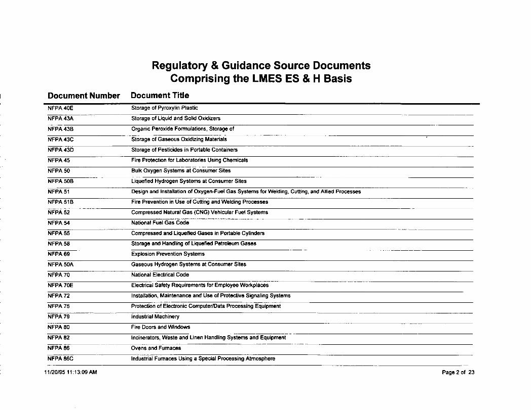
Regulatory & Guidance SourceComprising the LMES ES&
Document Number Document Title
DocumentsH Basis
NFPA 40E Storage of Pyroxylin Plastic
NFPA 43A Storage of Liquid and Solid Oxidizers
NFPA 43B Organic Peroxide Formulations, Storage of
NFPA 43C Storage of Gaseous Oxidizing Materials
NFPA 43D Storage of Pesticides in Portable Containers
NFPA 45 Fire Protetilon for Laboratories Using Chemicals
NFPA 50 Bulk Oxygen Systems at Consumer Sites
NFPA 50B Liquefied Hydrogen Systems at Consumer Sites
NFPA 51 Design and Installation of Oxygen-Fuel Gas Systems for Wekting, Cutting, and Allied Processes
NFPA51B Fire Prevention in Use of Cutting and WeldingProcesses
NFPA 52 Compressed Natural Gas (CNG) Vehicular Fuel Systems
NFPA 54 National Fuel Gas Code
NFPA 55 Compressed and Liquefied Gases in Portable Cylinders
NFPA 58 Storage and Handling of Lquefwd Petroleum Gases
NFPA 69 Explosion Prevention Systems
NFPA 50A Gaseous Hydrogen Systems at Consumer Sites
NFPA 70 National Electrical Code
NFPA 70E Electrical Safety Requirements for Employee Workplaces
NFPA 72 Installation, Maintenance and Use of Protective Signaling Systems
NFPA 75 Protection of Electronic Computer/Data Processing Equipment
NFPA 79 Industrial Machinery
NFPA 80 Fire Doors and Windows
NFPA 82 Incinerator, Waste and Linen Handling Systems and Equipment
NFPA 86 Ovens and Furnaces
NFPA 86C Industrial Furnaces Using a Special Processing Atmosphere
1112019511:13:09 AM Page 2 of 23
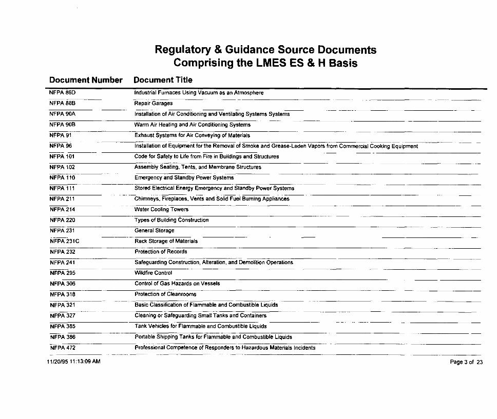
Regulatory & Guidance SourceComprising the LMES ES&
Document Number Document Title
DocumentsH Basis
NFPA 86D Industrial Furnaces Using Vacuum as an Atmosphere
NFPA 88B Repair Garages
NFPA 90A Installation of Air Conditioning and Ventilating Systems Systems
NFPA 90B Warm Air Heating and Air Conditioning Systems
NFPA 91 Exhaust Systems for Air Conveying of Materials
NFPA 96 Installation of Equipment for the Removal of Smoke and Grease-Laden Vapors from Commercial Cooking Equipment
NFPA 101 Code for Safety to Life from Fire in Buildings and Structures
NFPA 102 Assembly Seating, Tents, and Membrane Structures
NFPA 110 Emergency and Standby Power Systems
NFPA 111 Stored Electrical Energy Emergency and Standby Power Systems
NFPA211 Chimneys, Fireplaces, Vents and Solid Fuel Burning Appliances
NFPA 214 Water Cooling Towers
NFPA 220 Types of Building Construction
NFPA 231 General Storage
NFPA231C Rack Storage of Materials
NFPA 232 Protection of Records
NFPA 241 Safeguarding Construction, Alteration, and Demolition Operations
NFPA 295 Wildfire Control
NFPA 306 Control of Gas Hazards on Vessels
NFPA 318 Protection of Cleanrooms.—
NFPA 321 Basic Classification of Flammable and Combustible Liquids
NFPA 327 Cleaning or Safeguarding Small Tanks and Containera
NFPA 385 Tank Vehicles for Flammable and Combustible Liquids
NFPA 386 Portable Shipping Tanks for Flammable and Combustible Liquids
NFPA 472 Professional Competence of Responders to Hazardous Materials Incidents
1112019511:13:09 AM Page 3 of 23
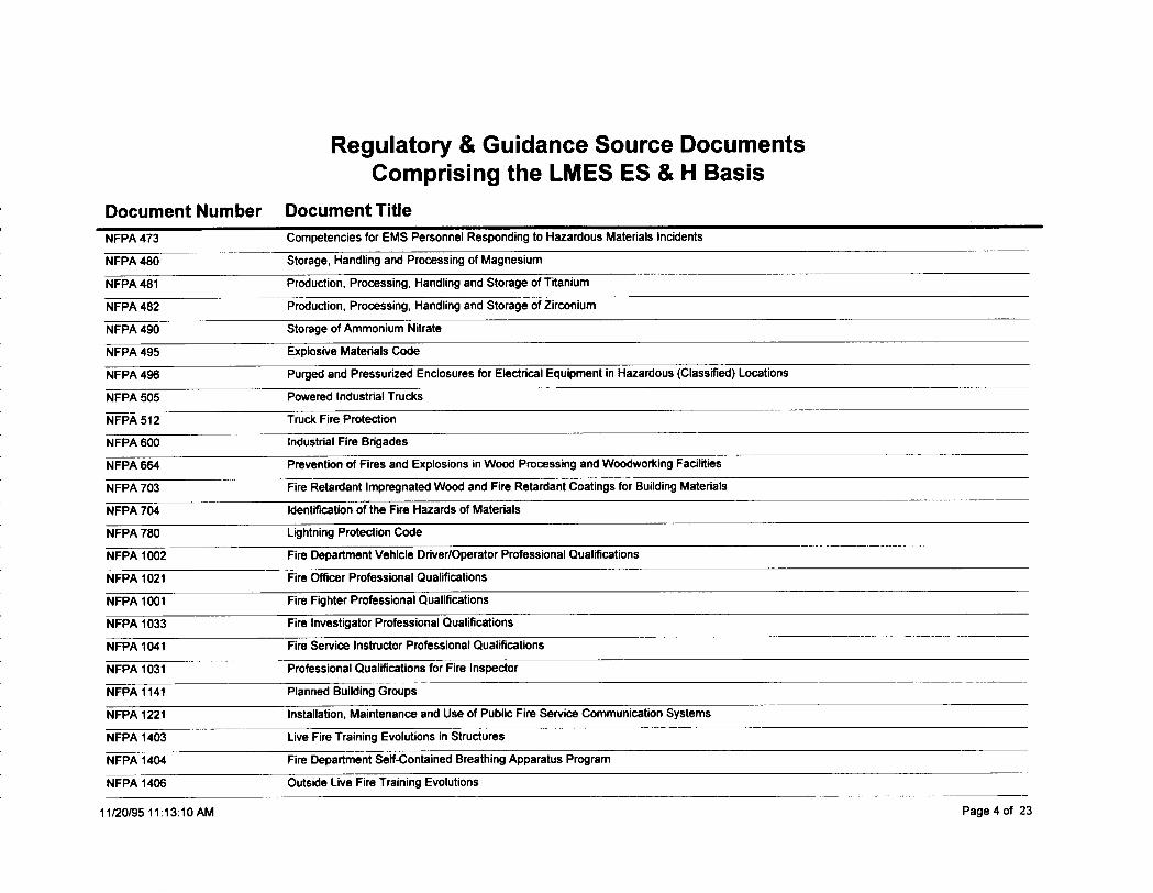
Regulatory & Guidance SourceComprising the LMES ES&
Document Number Document Title
DocumentsH Basis
NFPA 473 Competencies for EMS Personnel Responding to Hazardous Materials Incidents
NFPA 480 Storage, Handling and Processing of Magnesium
NFPA 481 Production, Processing, Handling and Storage of Titanium
NFPA 482 Production, Processing, Handling and Storage of Zirconium
NFPA 490 Storage of Ammonium Nitrate
NFPA 495 Explosive Materials Code
NFPA 498 Purged and Pressurized Enclosures for Electrical Equipment in Hazardous (Classified) Locations
NFPA 505 Powered Industrial Trucks
NFPA 512 Truck Fire Protection
NFPA 600 Industrial Fire Brigades
NFPA 664 Prevention of Fires and Explosions in Wood Processing and Woodworking Facilities
NFPA 703 Fire Retardant Impregnated Wood and Fire Retardant Coatings for Building Materials
NFPA 704 Identification of the Fire Hazards of Materials
NFPA 780 Lghtning Protection Code
NFPA 1002 Fire Department Vehicle Driver/Operator Professional Qualifications
NFPA 1021 Fire Offbr Professional Qualifications
NFPA 1001 Fire Fighter Professional Qualifications
NFPA 1033 Fire Investigator Professional Qualifications
NFPA 1041 Fire Service Instructor Professional Quaificetions
NFPA 1031 Professional Qualifications for Fire Inspector
NFPA 1141 Planned Building Groups
NFPA 1221 Installation, Maintenance and Use of Public Fire Service Communication Systems
NFPA 1403 Live Fire Training Evolutions in Structures
NFPA 1404 Fire Department Seti-Contained Breathing Apparatus Program
NFPA 1406 Outside Live Fire Training Evolutions
11/20/95 11:13 :1OAM Page 4 of 23
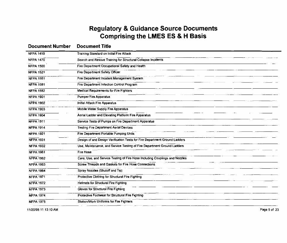
Regulatory & Guidance SourceComprising the LMES ES&
Document Number Document Title
DocumentsH Basis
NFPA 1410 Training Standard on Initial Fire Attack————.
NFPA 1470 Search and Rescue Training for Structural Collapse Incidents——
--—. —NFPA 1500 Fire Department Occupational Safety and Health
NFPA 1521 Fire Department Safety Ofker
NFPA 1561 ‘— Fire Department Incident Management System
NFPA 1581 Fire Department Infection Control Program
NFPA 1582 Medical Requirements for Fire Fighters
NFPA 1901 Pumper Fire Apparatus
NFPA 1902 Initial Attack Fire Apparatus
NFPA 1903 Mobile Water Supply Fire Apparatus
NFPA 1904 Aerial Ladder and Elevating Platform Fire Apparatus
NFPA 1911 Service Tests of Pumps on Fire Department Apparatus
NFPA 1914 Testing Fire Department Aerial Devices
NFPA 1921 Fire Department Portable Pumping Units
NFPA 1931 Design of and Design Verification Tests for Fire Department Ground Ladders
NFPA 1932 Use, Maintenance, and Service Testing of Fire Department Ground Ladders
NFPA 1961 Fire Hose
Care, Use, and Service Testing of Fire Hose Including Couplings and NozzlesNFPA 1962
NFPA 1963 Screw Threads and Gaskets for Fire Hose Connections
NFPA 1964 Spray Nozzles (Shutoff and Tip)
NFPA 1971 Protective Clothing for Structural Fire Fighting
NFPA 1972 Helmets for Structural Fire Fighting
NFPA 1973 Gloves for Structural Fire Fighting
NFPA 1974 Protective Footwear for Structural Fire Fighting
NFPA 1975 Station/Work Uniforms for Fire Fighters
11/20/95 11: I3:1OAM Page 5 of 23

Regulatory & Guidance Source DocumentsComprising the LMES ES & H Basis
Document Number Document Title
NFPA 1981 Open-Circuit Self-Contained Breathing Apparatus for Fire Fighters
NFPA 1982 Personal Alert Safety Systems (PASS) for Fire Fighters
NFPA 1983 Fire Service Life Safety Rope, Harness, and Hardware
NFPA 1991 Vapor-Protective Suits for Hazardous Chemical Emergencies
NFPA 1992 Liquid Splash-Protective Suits for Hazardous Chemical Emergencies
NFPA 1993 Support Function Protedive Garments for Hazardous Chemical Operations
NFPA 1999 Protective Clothing for Medical Emergency Operations
NFPA 2001 Clean Agent Fire Extinguishing Systems
NFPA 8501 Single Burner Boiler Operation
NFPA 8503 Pulverized Fuel Systems
NIOSH PUB 86-115 CRITERIA FOR A RECOMMENDED STD. - OCCUP. EXPOSURE TO HOT ENVIRONMENTS
NQA-1 STANDARD QUALITY REQUIREMENT EVALUATION CRITERIA I!?+SAFETY GUIDELINES
DOE-STD-1O27-92 Hazard Categorization and Accident Analysis Techniques for Compliance with DOE Order 5480.23, Nuclear Safety Analysis Reports
DOE-STD-1O32-92 Guide to Gocd Practices for Operations Organization and Administration
DOE-STD-1O73-93 Guide for Operational Configuration Management Programs
DoE/EM/RM/ol EM40MPR EM40 MANAGEMENT POLICIES AND REQUIREMENTS
DOE/EM/RM/02EM40MP EM40 MANAGEMENT PLAN
DOE/EP-0108 Standard for Fire Prote~lon of DOE Electronic Computer/Data Processing Systems
DOEIEV-0043 Standard on Fire Protedon for Portable Structures
DOE/OR 1006 REQUIREMENTS FOR THE ACCOMPLISHMENT OF CONSTRUCTION PROJECTS UTILIZING A CONSTRUCTION MANAGEMENTCONTRACTOR QUALITY
10 CFR 60 ATOMIC ENERGY ACT 1994
10 CFR 71 Nuclear Regulatory Commission
10 CFR 820 Procedural Rules for DOE Nuclear Activities
10 CFR 830.120 Nuclear Safety Management (Quality Assurance Requirements)
11/20/95 11:13 :IOAM Page 6 of 23
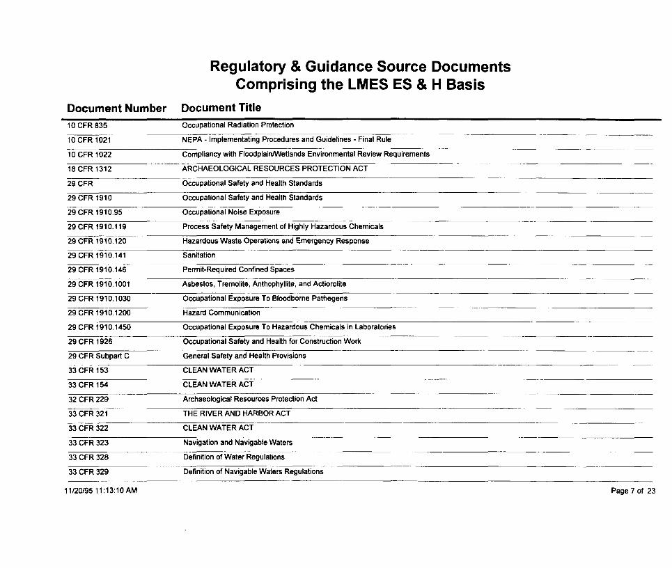
Regulatory & Guidance SourceComprising the LMES ES&
Document Number Document Title
DocumentsH Basis
10 CFR 835 Occupational Radiation Protection
10 CFR 1021 NEPA - Implementating Procedures and Guidelines - Final Rule.—
10 CFR 1022 Compliancy with FloodplainANetlands Environmental Review Requirements
18 CFR 1312 ARCHAEOLOGICAL RESOURCES PROTECTION ACT—
29 CFR Occupational Safety and Health Standards
29 CFR 1910 Occupational Safety and Health Standards
29 CFR 1910.95 Occupational Noise Exposure
29 CFR191O.119 Process Safety Management of Highly Hazardous Chemicals
29 CFR 1910.120 Hazardous Waste Operations and Emergency Response
29 CFR 1910.141 Sanitation
29 CFR 1910.146 Permit-Required Confined Spaces
29 CFR 1910.1001 Asbestos, Tremolite, Anthophyllite, and Actiorolite
29 CFR 1910.1030 Occupational Exposure To Bloodborne Pathegens
29 CFR 1910.1200 Hazard Communication
29 CFR 1910.1450 Occupational Exposure To Hazardous Chemicals in Laboratories
29 CFR 1926 Occupational Safety and Health for Construction Work
29 CFR Subpart C General Safety and Health Provisions—
33 CFR 153 CLEAN WATER ACT
33 CFR 154 CLEAN WATER ACT
32 CFR 229 Archaeological Resources Protection Act
33 CFR 321 THE RIVER AND HARBOR ACT
33 CFR 322 CLEAN WATER ACT
33 CFR 323 Navigation and Navigable Waters ‘-
33 CFR 328 Definition of Water Regulations
33 CFR 329 Definition of Navigable Waters Regulations
11/20/95 11:13 :1OAM Page 7 of 23
Regulatory & Guidance SourceComprising the LMES ES&
Document Number Document Title
DocumentsH Basis
33 CFR 330 CLEAN WATER ACT
36 CFR Federal Records; General
36 CFR 60 National Register of Historic Places
36 CFR 63 NATIONAL HISTORIC PRESERVATION ACT
36 CFR 65
36 CFR 68
NATIONAL HISTORIC PRESERVATION ACT
NATIONAL HISTORIC PRESERVATION ACT
36 CFR 78 NATIONAL HISTORIC PRESERVATION ACT
36 CFR 296 ARCHAEOLOGICAL RESOURCES PROTECTION ACT
36 CFR 800 Parks, Forests, and Public Property
40 CFR 11 National Resource Damage Assessments
40 CFR 50 CLEAN AIR ACT
40 CFR 53 Ambient Air Monitoring
40 CFR 58 CLEAN AIR ACT
40 CFR 60 Clean Air Act (Standards of Performance for New Stationary Sources)
40 CFR 61 CLEAN AIR ACT
40 CFR 68 Chemical Accident Prevention
40 CFR 69 Special Exemptions
40 CFR 72 Permits Regulations
40 CFR 82 Stratospheric Ozone Protection
40 CFR 109 Oil Removal Contingency Plans
4OCFR11O CLEAN WATER ACT
40 CFR 112 CLEAN WATER ACT
40 CFR 116 Designation of Hazardous Substances
40 CFR 122 CLEAN WATER ACT
40 CFR 130 Requirements for Water Quality Plan and Management
11/20/95 11:13:11 AM Page 8 of 23
Regulatory & Guidance SourceComprising the LMES ES&
Document Number Document Title
DocumentsH Basis
40 CFR 133 Regulation on Secondary Treatment——
40 CFR 141 SAFE DRINKING WATER ACT
40 CFR 142 SAFE DRINKING WATER ACT
40 CFR 143 SAFE DRINKING WATER ACT
40 CFR 144 SAFE DRINKING WATER ACT
40 CFR 146 SAFE DRINKING WATER ACT
40 CFR 147 State Underground Injection Program
40 CFR 148 SAFE DRINKING WATER ACT
40 CFR 165 FEDERAL INSECTICIDE, FUNGICIDE, AND RODENTICIDE ACT
40 CFR 171 FEDERAL INSECTICIDE, FUNGICIDE, AND RODENTICIDE ACT
40 CFR 191 ATOMIC ENERGY ACT
40 CFR 230 CLEAN WATER ACT
40 CFR 231 Clean Water Act
40 CFR 232 ActMities Exempt from Dredge and Fill Permit
40 CFR 241 RESOURCE CONSERVATION AND RECOVERY ACT
40 CFR 243 RESOURCE CONSERVATION AND RECOVERY ACT
40 CFR 245 RESOURCE CONSERVATION AND RECOVERY ACT
40 CFR 246 RESOURCE CONSERVATION AND RECOVERY ACT
40 CFR 260 RESOURCE CONSERVATION AND RECOVERY ACT
40 CFR 261 RESOURCE CONSERVATION AND RECOVERY ACT
40 CFR 262 RESOURCE CONSERVATION AND RECOVERY ACT
40 CFR 263 RESOURCE CONSERVATION AND RECOVERY ACT
40 CFR 264 RESOURCE CONSERVATION AND RECOVERY ACT
40 CFR 265 RESOURCE CONSERVATION AND RECOVERY ACT
40 CFR 266 RESOURCE CONSERVATION AND RECOVERY ACT
11/20/95 11:13:11 AM Page 9 of 23
Regulatory & Guidance Source DocumentsComprising the LMES ES & H Basis
Document Number Document Title
40 CFR 266 RESOURCE CONSERVATION AND RECOVERY ACT
40 CFR 267 RESOURCE CONSERVATION AND RECOVERY ACT
40 CFR 268 RESOURCE CONSERVATION AND RECOVERY ACT
40 CFR 270 RESOURCE CONSERVATION AND RECOVERY ACT
40 CFR 280 TECHNICAL STANDARDS & CORRECTING ACTION PROCEDURES FOR THE ANALYSIS OF POLLUTANTS
40 CFR 300 COMPREHENSIVE ENVIRONMENTAL RESPONSE, COMPENSATION, & LIABILITY ACT
40 CFR 302 COMPREHENSIVE ENVIRONMENTAL RESPONSE, COMPENSATION, & LIABILITY ACT
40 CFR 370 EMERGENCY PLANNING & COMMUNITY RIGHT-TO-KNOW ACT
40 CFR 372 EMERGENCY PIANNING & COMMUNITY RIGHT-TO-KNOW ACT
40 CFR 403 Clean Water Act (General Pretreatment Regulations for Existing and New Sources of Pollution)
40 CFR 761 TOXIC SUBSTANCES CONTROL ACT
40 CFR 1500 NATIONAL ENVORNMENTAL POLICY ACT
40 CFR 1501 NATIONAL ENVORNMENTAL POLICY ACT
40 CFR 1502 NATIONAL ENVORNMENTAL POLICY ACT
40 CFR 1503 NATIONAL ENVORNMENTAL POLICY ACT
40 CFR 1504 NATIONAL ENVORNMENTAL POLICY ACT
40 CFR 1505 NATIONAL ENVORNMENTAL POLICY ACT
40 CFR 1506 NATIONAL ENVORNMENTAL POLICY ACT
40 CFR 1507 NATIONAL ENVORNMENTAL POLICY ACT
41 CFR Federal Information Resources Management Regulation
43 CFR 3 NATIONAL HISTORIC PRESERVATION ACT
43 CFR 7 ARCHAEOLOGICAL RESOURCES PROTECTION ACT
49 CFR Federal Motor Carrier Safety Regulations
49 CFR 107 Hazardous Materials Regulations
49 CFR 171 HAZARDOUS MATERIALS TRANSPORTATION ACT
11/20/95 11:13:11 AM Page 10 of 23
Regulatory & Guidance SourceComprising the LMES ES&
Document Number Document Title
DocumentsH Basis
49 CFR 172 HAZARDOUS MATERIALS TRANSPORTATION ACT
49 CFR 173 HAZARDOUS MATERIALS TRANSPORTATION ACT
49 CFR 174 HA2ARDOUS MATERIALS TRANSPORTATION ACT
49 CFR 177 HAZARDOUS MATERIALS TRANSPORTATION ACT
49 CFR 178 HAZARDOUS MATERIALS TRANSPORTATION ACT—
49 CFR 180 HAZARDOUS MATERIALS TRANSPORTATION ACT
50 CFR 17 ENDANGERED SPECIES ACT
50 CFR 222 ENDANGERED SPECIES ACT
50 CFR 225 ENDANGERED SPECIES ACT
50 CFR 226 ENDANGERED SPECIES ACT
50 CFR 227 ENDANGERED SPECIES ACT
401 KAR 30 KENTUCKY WASTE MANAGEMENT ACT
401 KAR 31 KENTUCKY WASTE MANAGEMENT ACT
401 KAR32 KENTUCKY WASTE MANAGEMENT ACT
401 KAR33 KENTUCKY WASTE MANAGEMENT ACT
401 KAR 34 KENTUCKY WASTE MANAGEMENT ACT
401 KAR35 KENTUCKY WASTE MANAGEMENT ACT
401 KAR36 KENTUCKYWASTE MANAGEMENTACT
401 KAR 37 KENTUCKYWASTE MANAGEMENTACT
401 KAR 38 KENTUCKYWASTE MANAGEMENTACT
401 KAR 39 KENTUCKYWASTE MANAGEMENTACT
401 KAR 40 KENTUCKYWASTE MANAGEMENTACT
401 KAR 42 KENTUCKY UNDERGROUND STORAGE TANK ACT
401 KAR47&48 KENTUCKYWASTE MANAGEMENTACT
401 KAR 49 KENTUCKYWASTE MANAGEMENTACT
11/20/9511 :13:12AM Page llof 23
Regulatory & Guidance Source DocumentsComprising the LMES ES & H Basis
Document Number Document Title
401 KAR 5.010 KENTUCKY WATER POLLUTION CONTROL ACT
401 KAR 5.005 KENTUCKY WATER POLLUTION CONTROL ACT
401 KAR 5.015 KENTUCKY WATER POLLUTION CONTROL ACT
401 KAR 5.026 KENTUCKY WATER POLLUTION CONTROL ACT
401 KAR 5.029 KENTUCKY WATER POLLUTION CONTROL ACT
401 KAR 5.031 KENTUCKY WATER POLLUTION CONTROL ACT
401 KAR 5.045 KENTUCKY WATER POLLUTION CONTROL ACT
401 KAR 5.050 KENTUCKY WATER POLLUTION CONTROL ACT
401 KAR 5.055 KENTUCKY WATER POLLUTION CONTROL ACT
401 KAR 5.060 KENTUCKY WATER POLLUTION CONTROL ACT
401 KAR 5.065 KENTUCKY WATER POLLUTION CONTROL ACT
401 KAR 5.070 KENTUCKY WATER POLLUTION CONTROL ACT
401 KAR 5.075 KENTUCKY WATER POLLUTION CONTROL ACT
401 KAR 5.080 KENTUCKY WATER POLLUTION CONTROL ACT
401 KAR 5.090 KENTUCKY WATER POLLUTION CONTROL ACT
401 KAR 8.020 KENTUCKY WATER POLLUTION CONTROL ACT
401 KAR 8.030 KENTUCKY WATER POLLUTION CONTROL ACT
401 KAR 8.040 KENTUCKY WATER POLLUTION CONTROL ACT
401 KAR 8.050 KENTUCKY WATER POLLUTION CONTROL ACT
401 KAR 8.060 KENTUCKY WATER POLLUTION CONTROL ACT
401 KAR 8.070 KENTUCKY WATER POLLUTION CONTROL ACT
401 KAR 8.100 KENTUCKY WATER POLLUTION CONTROL ACT
401 KAR 8.150 KENTUCKY WATER POLLUTION CONTROL ACT
401 KAR 8.200 KENTUCKY WATER POLLUTION CONTROL ACT
401 KAR8.250 KENTUCKY WATER POLLUTION CONTROL ACT
11/20/9511 :13:12AM Page 12 of 23
u)Ill
Regulatory & Guidance SourceComprising the LMES ES&
Document Number Document Title
DocumentsH Basis
CHAPTER 1200-1-11.03 TENNESSEE SOLID WASTE DISPOSAL ACT
CHAPTER 1200-1-11.04 TENNESSEE SOLID WASTE DISPOSAL ACT
CHAPTER 1200-1-11.05 TENNESSEE SOLID WASTE DISPOSAL ACT
CHAPTER 1200-1-11.08 TENNESSEE SOLID WASTE DISPOSAL ACT
CHAPTER 1200-1-11.07 TENNESSEE SOLID WASTE DISPOSAL ACT
CHAPTER 1200-1-11.08 TENNESSEE SOLID WASTE DISPOSAL ACT
CHAPTER 1200-1-11.09 TENNESSEE SOLID WASTE DISPOSAL ACT
CHAPTER 1200-1-11.10 TENNESSEE SOLID WASTE DISPOSAL ACT
CHAPTER 1200-1-13.01 TENNESSEE HAZARDOUS WASTE MANAGEMENT ACT
CHAPTER 1200-1-13.02 TENNESSEE HAZARDOUS WASTE MANAGEMENT ACT
CHAPTER 1200-1-13.04 TENNESSEE HAZARDOUS WASTE MANAGEMENT ACT
CHAPTER 1200-1-15.01 TENNESSEE PETROLEUM UNDERGROUND STORAGE TANK ACT
CHAPTER 1200-1-15.02 TENNESSEE PETROLEUM UNDERGROUND STORAGE TANK ACT
CHAPTER 1200-1-15.03 TENNESSEE PETROLEUM UNDERGROUND STORAGE TANK ACT
CHAPTER 1200-1-15.04 TENNESSEE PETROLEUM UNDERGROUND STORAGE TANK ACT
CHAPTER 1200-1-15.05 TENNESSEE PETROLEUM UNDERGROUND STORAGE TANK ACT
CHAPTER 1200-1-15.08 TENNESSEE PETROLEUM UNDERGROUND STORAGE TANK ACT
CHAPTER 1200-1-15.07 TENNESSEE PETROLEUM UNDERGROUND STORAGE TANK ACT
CHAPTER 1200-1-15.08 TENNESSEE PETROLEUM UNDERGROUND STORAGE TANK ACT
CHAPTER 1200-1-15.09 TENNESSEE PETROLEUM UNDERGROUND STORAGE TANK ACT
CHAPTER 1200-1-15.10 TENNESSEE PETROLEUM UNDERGROUND STORAGE TANK ACT
CHAPTER 1200-1-15.11 TENNESSEE PETROLEUM UNDERGROUND STORAGE TANK ACT
CHAPTER 1200-3-3 TENNESSEE AIR QUALITY ACT
CHAPTER 1200-3-4 TENNESSEE AIR QUALITY ACT
CHAPTER 1200-3-5 TENNESSEE AIR QUALITY ACT
11/20/95 11:13 :12AM Page 14 of 23
Regulatory & Guidance SourceComprising the LMES ES &
Document Number Document Title
DocumentsH Basis
CHAPTER 1200-3-7 TENNESSEE AIR QUALITY ACT
CHAPTER 1200-3-8 TENNESSEE AIR QUALITY ACT
CHAPTER 1200-3-9 TENNESSEE AIR QUALITY ACT
CHAPTER 1200-3-1 0– - TENNESSEE AIR QUALITY ACT
CHAPTER 1200-3-11 TENNESSEE AIR QUALITY ACT
CHAPTER 1200-3-12 TENNESSEE AIR QUALITY ACT
CHAPTER 1200-3-14 TENNESSEE AIR QUALITY ACT
CHAPTER 1200-3-15 TENNESSEE AIR QUALITY ACT
CHAPTER 1200-3-16 TENNESSEE AIR QUALITY ACT
CHAPTER 1200-3-18 TENNESSEE AIR QUALITY ACT
CHAPTER 1200-3-20 TENNESSEE AIR QUALITY ACT
CHAPTER 1200-3-24 TENNESSEE AIR QUALITY ACT
CHAPTER 1200-3-26 TENNESSEE AIR QUALITY ACT
CHAPTER 12004-2 TENNESSEE WATER QUALITY CONTROL ACT
CHAPTER 1200-4-3 TENNESSEE WATER QUALITY CONTROL ACT
CHAPTER 1200-4-5 TENNESSEE WATER QUALITY CONTROL ACT
CHAPTER 1200-4-6 TENNESSEE WATER QUALITY CONTROL ACT
CHAPTER 1200+10 TENNESSEE WATER QUALITY CONTROL ACT
CHAPTER 1200-5-1 TENNESSEE DRINKING WATER ACT
EO 11990 Protection of Wetlands
EO 12088 Federal Compliance with Pollution Standards
EO 12777 Implementation of Section 311 of Clean Water Act—
EO 12843 Procurement of Ozone Depleting Substance
EO 12856 Federal Compliance with Right-to-Know and Pollution Prevention Requirements
EO 12873 – Federal Requisition, Recycling and Waste Prevention
11/20/95 11:13 :13AM Page 15 of 23
Regulatory & Guidance Source DocumentsComprising the LMES ES&H Basis
Document Number Document Title
EO 12898 Environmental Justice
EO 12915 Federal Implementation of the North American Agreement on Environmental Cooperation
EO 11514 FEDERAL AGENCY RECYCLING AND THE COUNCIL ON FEDERAL RECYCLING& PROCUREMENT& POLICY
EO 11593 FEDERAL AGENCY RECYCLING AND THE COUNCIL ON FEDERAL RECYCLING& PROCUREMENT& POLICY
EO 11988 FEDERAL AGENCY RECYCLING AND THE COUNCIL ON FEDERAL RECYCLING& PROCUREMENT& POLICY
EXEC ORDER 11990 FEDERAL AGENCY RECYCLING AND THE COUNCIL ON FEDERAL RECYCLING& PROCUREMENT& POLICY
EXEC ORDER 12088 FEDERAL AGENCY RECYCLING AND THE COUNCIL ON FEDERAL RECYCLING& PROCUREMENT& POLICY
EO 12580 FEDERAL AGENCY RECYCLING AND THE COUNCIL ON FEDERAL RECYCLING& PROCUREMENT& POLICY
EXEC ORDER 12777 FEDERAL AGENCY RECYCLING AND THE COUNCIL ON FEDERAL RECYCLING& PROCUREMENT& POLICY
EO 12780 FEDERAL AGENCY RECYCLING AND THE COUNCIL ON FEDERAL RECYCLING& PROCUREMENT& POLICY
EXEC ORDER 12643 FEDERAL AGENCY RECYCLING AND THE COUNCIL ON FEDERAL RECYCLING& PROCUREMENT& POLICY
EXEC ORDER 12856 FEDERAL AGENCY RECYCLING AND THE COUNCIL ON FEDERAL RECYCLING& PROCUREMENT& POLICY
Fed. Facility Agmt. Federal Facility Agreement
FFCAKCLP Federal Facilii Compliance Agn?emenfloxicity Proosdure Addressing Waste Characterization
OAC 1301:7-9 OHIO UNDERGROUND STORAGE TANK tAW
OAC 1501:15 OH lO WATER POLLUTION CONTROL ACT
OAC 3745-1 OHIO WATER POLLUTION CONTROL ACT
OAC 3745-3 OHIO WATER POLLUTION CONTROL ACT
OAC 3745-15 OHIO AIR POLLUTION CONTROL ACT
OAC 3745-16 OHIO AIR POLLUTION CONTROL ACT
OAC 3745-17 OHIO AIR POLLUTION CONTROL ACT
OAC 3745-18 OHIO AIR POLLUTION CONTROL ACT
OAC 3745-19 OHIO AIR POLLUTION CONTROL ACT
OAC 3745-21 OHIO AIR POLLUTION CONTROL ACT
OAC 3745-23 OHlO AIR POLLUTION CONTROL ACT
11/20/95 11:13 :13AM Page 16 of 23
Regulatory & Guidance Source DocumentsComprising the LMES ES & H Basis
Document Number Document Title
OAC 3745-25 OHIO AIR POLLUTION CONTROL ACT
OAC 3745-27 OHlO SOLID& HAZARDOUS WASTE DISPOSAL LAW
OAC 3745:28-37 OHIO SOLID & HAZARDOUS WASTE DISPOSAL LAW
OAC 3745-29 OHIO SOLID AND HAZARDOUS WASTE DISPOSAL IAW
OAC 3745-30 OHIO SOLID AND HAZARDOUS WASTE DISPOSAL LAW
OAC 3745-33 OHIO WATER POLLUTION CONTROL ACT
OAC 3745-34 OHIO SAFE DRINKING WATER ACT
OAC 3745-35 OHlO AIR POLLUTION CONTROL ACT
OAC 3745-36 OHlO SOLID AND HAZARDOUS WASTE DISPOSAL LAW
OAC 374545 — OHIO AIR POLLUTION CONTROL ACT
OAC 3745-49 OHIO AIR POLLUTION CONTROL ACT
OAC 3745-50 OHIO SOLID & HAZARDOUS WASTE DISPOSAL LAW
OAC 3745-51 OHIO AIR POLLUTION CONTROL ACT
OAC 3745-52 OHIO AIR POLLUTION CONTROL ACT
OAC 3745-53 OHIO AIR POLLUTION CONTROL ACT
OAC 3745-54 OHIO AIR POLLUTION CONTROL ACT
OAC 3745-55 OHlO SOLID& HAZARDOUS WASTE DISPOSAL LAW
OAC 3745-56 OHIO SOLID & HAZARDOUS WASTE DISPOSAL IAW
OAC 3745-57 OHIO SOLID & HAZARDOUS WASTE DISPOSAL LAW
OAC 3745-58 OHIO SOLID & HAZARDOUS WASTE DISPOSAL LAW
OAC 3745-59 OHIO SOLID & HAZARDOUS WASTE DISPOSAL IAW
OAC 3745-65 OHIO SOLID & HAZARDOUS WASTE DISPOSAL LAW
OAC 3745-66 OHlO SOLID& HAZARDOUS WASTE DISPOSAL LAW
OAC 3745-67 OHIO SOLID & HAZARDOUS WASTE DISPOSAL LAW
OAC 3745-68 OHIO SOLID & HAZARDOUS WASTE DISPOSAL LAW
11/20/95 11:13 :13AM Page 17 of 23
Regulatory & Guidance SourceComprising the LMES ES &
Document Number Document Title
DocumentsH Basis
OAC 3745-69 OHIO SOLID & HAZARDOUS WASTE DISPOSAL LAW
OAC 3745-71 OHIO AIR POLLUTION CONTROL ACT
OAC 3745-75 OHIO AIR POLLUTION CONTROL ACT
OAC 3745-81 OHIO SAFE DRINKING WATER ACT
OAC 3745-100 OHIO SOLID & HAZARDOUS WASTE DISPOSAL LAW
OAC 3750-1 OHIO EMERGENCY PLANNING AND COMMUNITY RIGHT-TO-KNOW ACT
OAC 3750-10 OHIO EMERGENCY PUNNING AND COMMUNITY RIGHT-TO-KNOW ACT
OAC 3750-15 OHIO EMERGENCY PLANNING AND COMMUNIW RIGHT-TO-KNOW ACT
OAC 3750-20 OHIO EMERGENCY PIANNING AND COMMUNITY RIGHT-TO-KNOW ACT
OAC 3750-25 OHlO EMERGENCY PLANNING AND COMMUNITY RIGHT-TO-KNOW ACT
OAC 3750-50 OHIO EMERGENCY PLANNING AND COMMUNITY RIGHT-TO-KNOW ACT
Ohio AIP State of Ohio Agreement in Principle
Ohio Regulation Basic State Requirements Ohio Rules of Evidence
OR FFCA Oak Ridge Facility Compliance Agreement
PGDP Admin. Order Administrate Order by Consent for Paducah Gaseous Dffusion Plant
PGDP AIP Agreement in Principle for Paducah Gaseous Diffusion Plant
PL101-5O8 POLLUTION PREVENTION ACT OF 1990
PL102-386 FEDERAL FACILITY COMPLIANCE ACT
PORTS Consent Decree Portsmouth Consent Decree
PORTS Consent Order Pofismouth Consent Order
Term Code Basic State Requirements Tennessee Code Annotated
TITLE 68-211 TENNESSEE SANITARY LANDFILL AREAS ACT
TITLE 68-213 TENNESSEE SANITARY IANDFILL AREAS ACT
TN Oversight Agmt. Tennessee Oversight Agreement (TOA)
TSCA FFCA TSCA Federal Facilities Compliance Agreement for PCB Issues of Uranium Enrichment Facilities
11/20/9511 :13:14AM Page 18 of 23
Regulatory & Guidance SourceComprising the LMES ES&
Number Document Title
DocumentsH Basis
U. S. DOE Memo Management of Cultural Resources at DOE Facilities—....— ...—.-—..
1300.2A DOE Technical Standards Program
1360.2B Unclassified Computer Securi Program
1540.2 Hazardous Material Packaging for Transport - Administrative Procedures
4330.4A Maintenance Management program
4330.4B Maintenance Management Program
4700.1 Project Management System.—
5000.3B Occurrence Reporting and Processing of Operations Information
5400.1 General Environmental Protection Program
5400.4 Comprehensive Environmental Response, Compensation, and Liability Act Requirements
5400.5 Radiation Protedlon of the Public and the Environment
5480.3 Safety Requirements for the Packaging and Transportation of Hazardous Materials, Hazardous Substances, and Hazardous Wastes
5480.4 Environmental Protection, Safety, and Health Protedlon Standards
5480.5 Safety of Nuclear Facilities
5480.6 Safety of DOE Owned Reactors
5480.7A Fire Protection
5480.8A Contractor Occupational Medical Program
5480.9 Construction Safety and Health Program
5480.10 Contractor Industrial Hygiene Program
5480.11 Radiation Protection for Occupational klforke~
5480.15
5480.13 Aviation Safety
Department of Energy Laboratory Accreditation Program for Personnel Dosimetry
5480.16 Firearms Safety
5480.17 Site Safety Representatives
5480.18A Accreditation of Performance-Based Training for Category A Reactors and Nuclear Facilities
11/20/9511 :13:14AM Page 19 of 23
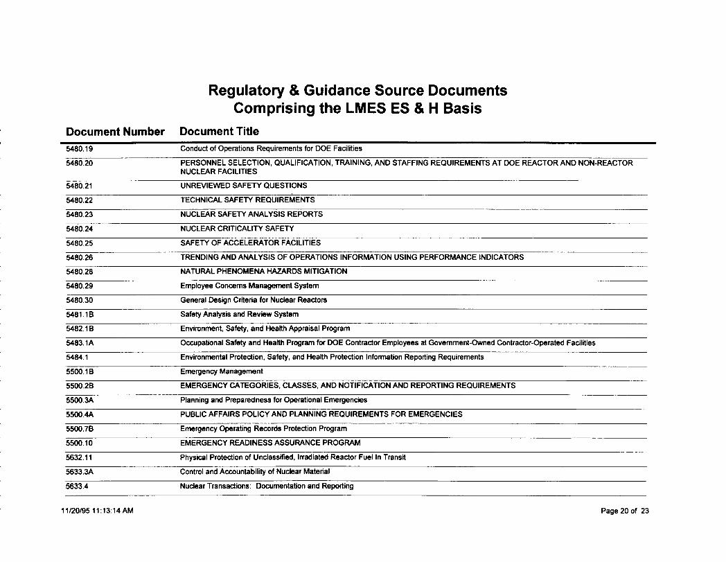
Regulatory & Guidance Source DocumentsComprising the LMES ES & H Basis
Document Number Document Title
5480.19 Conduct of Operations Requirements for DOE Facilities
5480.20 PERSONNEL SELECTION, QUALIFICATION, TRAINING, AND STAFFING REQUIREMENTS AT DOE REACTOR AND NON-REACTORNUCLEAR FACILITIES
5480.21 UNREVIEWED SAFETY QUESTIONS
5480.22 TECHNICAL SAFETY REQUIREMENTS
5480.23 NUCLEAR SAFETY ANALYSIS REPORTS
5480.24 NUCLEAR CRITICALITY SAFETY
5480.25 SAFETY OF ACCELERATOR FACILITIES
5480.26 TRENDING AND ANALYSIS OF OPERATIONS INFORMATION USING PERFORMANCE INDICATORS
5480.28 NATURAL PHENOMENA HAZARDS MITIGATION
5480.29 Employee Concerns Management System
5480.30 General Desgn Criteria for Nuclear Reactors
5481.1 B Safety Analysis and Review System
5482.1 B Environment, Safety, and Health Appraisal Program
5483.1A Occupational Safety and Health Program for DOE Contractor Employees at Government-Owned Contractor-Operated Facilities
5464.1 Environmental Protection, Safety, and Health Protection Information Reporting Requirements
5500.1 B Emergency Management
5500.2B EMERGENCY CATEGORIES, ClASSES, AND NOTIFICATION AND REPORTING REQUIREMENTS
5500.3A Planning and Preparedness for Operational Emergencies
5500.4A PUBLIC AFFAIRS POLICY AND PLANNING REQUIREMENTS FOR EMERGENCIES
5500.7B Emergency Operating Records Protection Program
5500.10 EMERGENCY READINESS ASSURANCE PROGRAM
5632.11 Physical Protection of Unclassified, Irradiated Reactor Fuel In Transit
5633.3A Control and Accountability of Nuclear Material
5633.4 Nuclear Transactions: Documentation and Reporting
11/20/95 11:13 :14AM Page 20 of 23
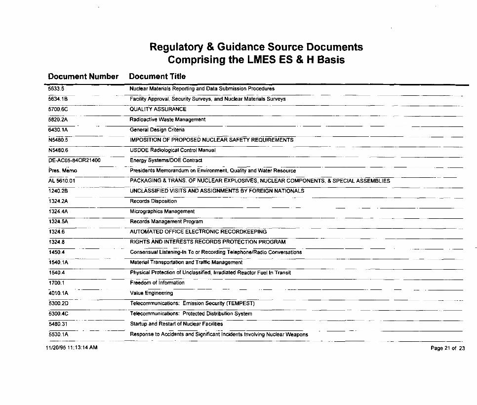
Regulatory & Guidance Source DocumentsComprising the LMES ES & H Basis
Document Number Document Title
5633.5 Nuclear Materials Repotting and Data Submission Procedures
5634.1 B Facility Approval, Security Surveys, and Nuclear Materials Surveys
5700.6C QUALITY ASSURANCE
5820.2A Radioactive Waste Management
6430.lA General Design Criteria
N5480.5 IMPOSITION OF PROPOSED NUCLEAR SAFE~ REQUIREMENTS
N5480.6 USDOE Radiological Control Manual
DE-AC05-840R21 400 Energy Systems/DOE Contract
Pres. Memo Presidents Memorandum on Environment, QuaIii and Water Resource
AL 5610.01 PACKAGING & TRANS. OF NUCLEAR EXPLOSIVES, NUCLEAR COMPONENTS, & SPECIAL ASSEMBLIES
1240.2B UNCLASSIFIED VISITS AND ASSIGNMENTS BY FOREIGN NATIONALS
1324.2A Records Disposition
1324.4A Micrographics Management
1324.5A Records Management Program
1324.6 AUTOMATED OFFICE ELECTRONIC RECORDKEEPING
1324.8 RIGHTS AND INTERESTS RECORDS PROTECTION PROGRAM
1450.4 Consensual Listening-In To or Recording Telephone/Radio Conversations
1540.lA Material Transportation and Traffic Management
1540.4 Physical Protection of Unclassified, Irradiated Reactor Fuel In Transit
1700.1 Freedom of Information
401O.1A Value Engineering
5300.2D Telecommunications: Emission Securii (TEMPEST)
5300.4C Telecommunications: Protected Distribution System
5480.31 Startup and Restart of Nuclear Facilities
5530.lA Response to Accidents and Significant Incidents Involving Nuclear Weapons
11/20/95 11:13 :14AM Page 21 of 23
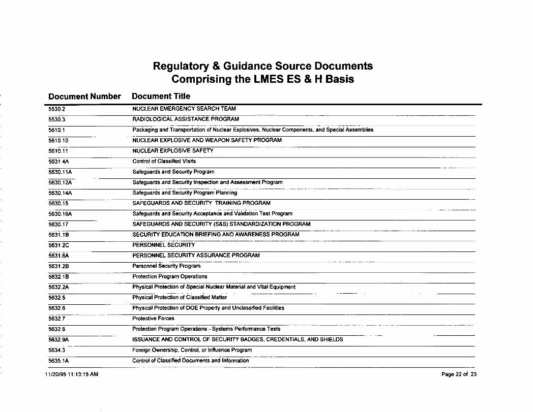
Regulatory & Guidance SourceComprising the LMES ES&
Document Number Document Title
DocumentsH Basis
5530.2 NUCLEAR EMERGENCY SEARCH TEAM
5530.3 RADIOLOGICAL ASSISTANCE PROGRAM
5610.1 Packaging and Transportation of Nuclear Explosives, Nuclear Components, and Special Assemblies
5610.10 NUCLEAR EXPLOSIVE AND WEAPON SAFETY PROGRAM
5610.11 NUCLEAR EXPLOSIVE SAFETY
5631 .4A Control of Classified Visits
5630.llA Safeguards and Security Program
5630.12A Safeguards and Sewrity Inspection and Assessment Program
5630. 14A Safeguards and Sewrity Program Planning
5630.15 SAFEGUARDS AND SECURITY TRAINING PROGRAM
5630. 16A Safeguards and Security Acceptance and Validation Test Program
5630.17 SAFEGUARDS AND SECURITY (S&S) STANDARDIZATION PROGRAM
5631.1 B SECURITY EDUCATION BRIEFING AND AWARENESS PROGRAM
5631 .2C PERSONNEL SECURITY
5631 .6A PERSONNEL SECURllV ASSURANCE PROGRAM
5631 .2B Personnel Securfty Program
5632.IB Protection Program Operations
5632.2A Physical Protection of Special Nuclear Material and Vital Equipment
5632.5 Physical Protetilon of Classified Matter
5632.6 Physical Protedlon of DOE Propwly and Unclassified Facilities
5632.7 Protective Forces
5632.8 Protection Program Operations - Systems Performance Tests
5632.9A ISSUANCE AND CONTROL OF SECURITY BADGES, CREDENTIALS, AND SHIELDS
5634.3 Foreign Ownership, Control, or Influencs Program
5635.1A Control of Classified Documents and information
11/20/95 11:13 :15AM Page 22 of 23
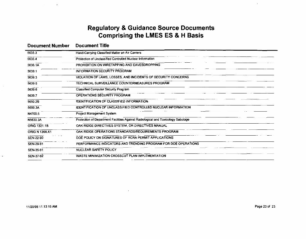
Regulatory & Guidance Source DocumentsComprising the LMES ES & H Basis
Document Number Document Title
5635.3 Hand-Cartying Classified Matter on Air Carriem
5635.4 Protection of Unclassified Controlled Nuclear Information
5636. 1A PROHIBITION ON WIRETAPPING AND EAVESDROPPING
5639.1 INFORMATION SECURITY PROGRAM
5639.3 VIOtATION OF LAWS, LOSSES, AND INCIDENTS OF SECURITY CONCERNS
5639.5 TECHNICAL SURVEILLANCE COUNTERMEASURES PROGRAM
5639.6 Classified Computer Security Program
5639.7 OPERATIONS SECURITY PROGRAM
5650.2B IDENTIFICATION OF CLASSIFIED INFORMATION
5650.3A IDENTIFICATION OF UNCLASSIFIED CONTROLLED NUCLEAR INFORMATION
N4700.5 Project Management System—..
N5630.3A Protection of Department Facilities Against Radiological and Toxicology Sabotage
ORIG 1321.lB OAK RIDGE DIRECTIVES SYSTEM, OR DIRECTIVES MANUAL
ORIG N 1300.X1 OAK RIDGE OPERATIONS STANDARDS/REQUIREMENTS PROGRAM
SEN-22-90 DOE POLICY ON SIGNATURES OF RCRA PERMIT APPLICATIONS
SEN-29-91 — PERFORMANCE INDICATORS AND TRENDING PROGRAM FOR DOE OPERATIONS
SEN-35-91 NUCLEAR SAFETY POLICY
SEN-37-92 WASTE MINIMIZATION CROSSCUT PLAN IMPLEMENTATION
1112019511 :13:15AM Page 23 of 23


![1 force the terms of the […] - iranwatch.org · Amount of low -enriched UF6 produced 300kgIncrease in amount of this UF6 since ... monitoring in Iran in light of United Nations](https://img.pdfslide.net/doc/110x75/5b043b447f8b9a0a548d3d1a/1-force-the-terms-of-the-of-low-enriched-uf6-produced-300kgincrease-in.jpg)