Embed Size (px)
Citation preview
NOx CONTROL FOR
HIGH ASH COALS
DR MALGORZATA WIATROS-MOTYKA
& HERMINÉ NALBANDIAN-SUGDEN
CC C/ 2 8 5 A p r i l 2 0 1 8
I E A C L E A N C O A L C E N T R E – N O x C O N T R O L F O R H I G H A S H C O A L S
2
N Ox CONTROL FO R HIGH
ASH COALS
I E A C L E A N C OA L C E N T R E A P S L E Y H OU S E , 1 7 6 U P P E R R I C H M ON D R OA D
L ON D ON , S W 1 5 2 S H U N I T E D K I N G D OM
+4 4 [ 0 ] 2 0 3 9 0 5 3 8 7 0
W W W . I E A - C OA L . ORG
I E A C L E A N C O A L C E N T R E – N O x C O N T R O L F O R H I G H A S H C O A L S
3
AUTHORS DR MALG ORZATA WI ATROS - MOTYKA &
H ERMI NÉ NAL B ANDI AN - SUG DEN
IEA REPORT NU MBER C CC/28 5
ISBN 9 78–9 2–9 029–608-9
© IEA CLEAN COAL CEN T RE
PU BLICATION DATE APRI L 2018
I E A C L E A N C O A L C E N T R E – N O x C O N T R O L F O R H I G H A S H C O A L S
4
P R E F A C E
This report has been produced by the IEA Clean Coal Centre and is based on a survey and analysis of
published literature, and on information gathered in discussions with interested organisations and
individuals. Their assistance is gratefully acknowledged. It should be understood that the views expressed
in this report are our own, and are not necessarily shared by those who supplied the information, nor by
our member organisations.
The IEA Clean Coal Centre is a Technology Collaboration Programme of the International Energy Agency
(IEA) which was itself founded in 1974 by member countries of the Organisation for Economic
Co-operation and Development (OECD). The IEA examines the full spectrum of energy issues including
oil, gas and coal supply and demand, renewable energy technologies, electricity markets, energy efficiency,
access to energy, demand side management and much more. Through its work, the IEA advocates policies
that will enhance the reliability, affordability and sustainability of energy in its 29 member countries and
beyond.
The IEA Clean Coal Centre was established in 1975 and has contracting parties and sponsors from:
Australia, China, the European Commission, Germany, India, Italy, Japan, Poland, Russia, South Africa,
Thailand, the UAE, the UK and the USA.
The overall objective of the IEA Clean Coal Centre is to continue to provide our members, the IEA Working
Party on Fossil Fuels and other interested parties with definitive and impartial information on how coal
can continue to be part of a sustainable energy mix worldwide. This includes the definition of future
technology trends that will support the use of coal within the framework of climate targets as set out by
the UN Framework Convention on Climate Change. We consider all aspects of coal production, transport,
processing and utilisation, within the rationale for balancing security of supply, affordability and
environmental issues. These include lowering greenhouse gas emissions while reducing water stress,
ensuring poverty alleviation through universal access to electricity and meeting other sustainability and
socially led goals.
Neither IEA Clean Coal Centre nor any of its employees nor any supporting country or organisation, nor
any employee or contractor of IEA Clean Coal Centre, makes any warranty, expressed or implied, or
assumes any legal liability or responsibility for the accuracy, completeness or usefulness of any
information, apparatus, product or process disclosed, or represents that its use would not infringe
privately-owned rights.
I E A C L E A N C O A L C E N T R E – N O x C O N T R O L F O R H I G H A S H C O A L S
5
A B S T R A C T
Many countries have strict emission limits for nitrogen oxides (NOx) and so NOx control systems are
widely used. India has recently introduced NOx emission limits which means that pollution control
technologies will need to be installed. However, in India there is limited operational experience with NOx
control systems. In addition, Indian coals have a high level of inherent ash which can influence the
behaviour of some NOx control systems, and so affect the selection process. Primary measures for NOx
control from coal-fired power plants include low NOx burners (LNBs), overfire air systems (OFA), fuel
reburning, flue gas recirculation, fuel biasing, low excess air and combustion optimisation.
Post-combustion NOx control includes selective catalytic reduction, selective non-catalytic reduction
and multi-pollutant control systems. Retrofit of primary measures (LNBs and OFA) has been
recommended to take place during next scheduled plant outages, and for many plants this could occur by
2019. However, control strategies for individual plants will be needed to ascertain the appropriateness of
installing post-combustion technologies or various combinations of NOx control measures. Hence,
installation of secondary NOx controls is not expected before tests results from SCR and SNCR on NTPC
units are known.
I E A C L E A N C O A L C E N T R E – N O x C O N T R O L F O R H I G H A S H C O A L S
6
A C R O N Y M S A N D A B B R E V I A T I O N S
AH air heater
AIG ammonia injection grid
AQCS air quality control systems
BAT best available technology
BOFA boosted overfire air
BREF best available technology reference document
BZS burner zone stoichiometry
CEA Central Electricity Authority (India)
CEM continuous emissions monitoring
CMP catalyst management plan
CCMP comprehensive catalyst management plan
CFB circulating fluidised bed
CIA carbon in ash
CFD computational fluid dynamic
CKM continuous kinetic modelling
CPSI cells per square inch
CSE Centre for Science and Environment (New Delhi, India)
EoI expression of Interest
EPA Environmental Protection Agency, USA
ESP electrostatic precipitator
FBC fluidised bed combustion
FF fabric filter
FGD flue gas desulphurisation
FGR flue gas recirculation
IED Industrial Emissions Directive (EU)
LEA low excess air
LNB low NOx burner
LOI loss-on-ignition
LPA large particle ash
MoEFCC Ministry of Environment Forest and Climate Change (India)
NOx nitrogen oxides
NRPC Government of India Northern Region Power Committee
NTPC National Thermal Power Corporation (India)
OFA overfire air
O&M operation and maintenance
PCC pulverised coal combustion
PA primary air
PM particulate matter
ppm parts per million
R&M renovation and modernisation
I E A C L E A N C O A L C E N T R E – N O x C O N T R O L F O R H I G H A S H C O A L S
7
ROFA rotating opposed fire air
SA secondary air
SCR selective catalytic reduction
SNCR selective non-catalytic reduction
SRPC Government of India Southern Region Power Committee
SOFA separated overfire air
TT tilting tangential
A C K N O W L E D G E M E N T S
The following individuals are acknowledged for their generous assistance in the preparation of this
report:
John Boyle Fuel Tech Inc, USA
Roger Brandwood Uniper Technologies Ltd, UK
Piers de Havilland Fuel Tech Srl, Italy
Nick Hutson EPA, USA
Anthony Jones EPA, USA
Nandakumar Krishnamurthy Fuel Perf Tech Pro LLC, USA
Daniel Nabagło PGE Energia Ciepła S.A., Poland
Sanjay Pande NTPC, India
Jim Peters Hamon, USA
David Smith Doosan Babcock Limited, UK
Scott Smouse DOE, USA
Larry Sorrels EPA, USA
Blake Stapper Aecom USA
Krzysztof Szczepanek PGE Energia Ciepła S.A., Poland
Moresh Wankhede Doosan Babcock Limited, UK
Graham Welford G Welford Ltd, UK
Felix Wilde GE Power, Germany
Robert Żmuda SBB Energy SA, Poland
I E A C L E A N C O A L C E N T R E – N O x C O N T R O L F O R H I G H A S H C O A L S
8
C O N T E N T S
PRE FACE 4
ABST RACT 5
ACRONYMS AND ABBREVI AT IONS 6
LIST OF FIGU RES 1 0
LIST OF T ABLES 11
EXECUTIVE SU MMARY 1 2
1 INTRODUCT ION 14
2 COAL QU ALIT Y AND NO x FORMAT ION 1 6
2.1 Combustion conditions 16
2.2 Impact of coal properties on NOx emissions 18
2.3 India 19
3 PRIMARY MEASU RES FOR NO x CONTROL 23
3.1 Low NOx burners (LNBs) 23
3.2 Overfire air (air staging) 24
3.2.1 Boosted overfire air (BOFA) 25
3.2.2 Rotating opposed fire air (ROFA) 25
3.3 Fuel reburning (staging) 26
3.4 Flue gas recirculation (FGR) 26 3.5 Fuel biasing 27
3.6 Low excess air (LEA) 27
3.7 Combustion optimisation 27
3.8 Primary NOx control measures for high ash coal 28
3.9 Comments 31
4 SELECTIVE CAT ALYTIC REDU CT ION (SCR) 33
4.1 The principle and mechanism of NOx removal 33
4.2 SCR system layouts 34
4.3 SCR for high ash coal 36
4.3.1 Issues with equipment and their mitigation 37
4.4 SCR catalysts 39
4.5 Catalyst issues and solutions with high ash coals 42 4.6 Role of SCR catalyst in mercury control 45
4.7 Comments 46
5 SELECTIVE NON-CAT ALYTIC REDUCTION (SNCR) 4 8
5.1 Umbrella-SNCR from GE 49
5.2 Advanced-SNCR using multiple nozzle lances from Fuel Tech Inc 51
5.3 Adaptive Non-Catalytic Reduction (ANCR®) from MAL environment technology 52
5.4 ROTAMIX® from Mobotec 54
5.5 Hybrid SNCR/SCR 54
5.5.1 I-NOx from Fuel Tech Inc 55
5.6 Selective non-catalytic reduction for high ash coals 55
5.6.1 Turceni power plant, use of GE Umbrella SNCR 56
5.6.2 Patnow I lignite power plant in Poland, use of LNBs, OFA and SNCR 57 5.6.3 Opole lignite power plant in Poland, use of LNBs, ROFA and SNCR 61
5.7 Comments 64
I E A C L E A N C O A L C E N T R E – N O x C O N T R O L F O R H I G H A S H C O A L S
9
6 MU LT I- POLLUT ANT AND EMERGING NO x CONT ROL TECHNOLOGIE S 6 6
6.1 ReACT™ 66
6.2 SNOX™ 69
6.3 UltraCat 69 6.4 LoTOx™ 71
6.5 Multi-pollutant and emerging NOx control methods for high ash coals 72
7 CHALLENGES FOR INST A LLATION OF NO x CONT ROL TECHNOLOGIE S IN
INDIA 74
8 CONCLUSIONS 78
9 REFERENCES 80
SOU RCES FOR IMAGES 87
I E A C L E A N C O A L C E N T R E – N O x C O N T R O L F O R H I G H A S H C O A L S
10
L I S T O F F I G U R E S
Figure 1 Influence of combustion temperature on the amount of NOx produced from the three
NOx formation mechanisms 17
Figure 2 Total installed capacity in India as of December 2017 20
Figure 3 Installed generation capacity as of March 2017 and projected in 2022 and 2027 20
Figure 4 Potential performance of an OFA system for various international coals 25
Figure 5 The variation of key combustion parameters with air/fuel ratio, showing the potential
efficiency improvements achievable with optimised combustion 28
Figure 6 Doosan Babcock and Doosan Heavy Industries’ high ash coal (HAC) burner designed for
the Indian market 29
Figure 7 Doosan Heavy Industries’ high ash coal burner exit flow field CFD computation inside the
CCTF 30
Figure 8 Schematic of Bypass Over Fire Air System at Suratgarh 250 MW boiler 31
Figure 9 SCR configurations 36
Figure 10 Main types of SCR catalyst 40
Figure 11 Examples of CORMETECH different catalyst types, their pitch sizes and cell numbers in
relation to dust content in the flue gas 40
Figure 12 BHEL’s SCR pilot test facility 44
Figure 13 Example of relationship between CO, temperature and NOx 49
Figure 14 Position of the Umbrella SNCR in a boiler in comparison to a traditional SNCR and SCR 50
Figure 15 SNCR and U-SNCR position comparison in relation to boiler load variations 50
Figure 16 Multiple nozzle lance 52
Figure 17 ANCR® tilting lance, TL type 53
Figure 18 Double lance 53
Figure 19 Rotating lance 53
Figure 20 Retractable and rotating lance 53
Figure 21 ROTAMIX® injector 54
Figure 22 NOx emissions before burner modification, and after installation of ROFA and
ROTAMIX® systems 60
Figure 23 ROTAMIX® urea consumption in correlation to ammonia slip over different unit load 60
Figure 24 NOx emissions after installation of ROFA and ROTAMIX® systems 63
Figure 25 Annual emissions after installation of ROFA and ROTAMIX® systems 64
Figure 26 Detailed schematic of single stage ReACT™ system 67
Figure 27 Two stage configuration of ReACT™ 67
Figure 28 Configuration of ReACT™ system in Isogo unit 2 68
Figure 29 UltraCat’s options for multi-pollutant capture 70
Figure 30 UltraCat’s test performance on lignite fired power plant 70
I E A C L E A N C O A L C E N T R E – N O x C O N T R O L F O R H I G H A S H C O A L S
11
L I S T O F T A B L E S
Table 1 New emission norms in India 14
Table 2 SCR catalyst poisoning and degradation mechanisms 41
Table 3 Characteristics of the Indian coal tested in BHEL SCR pilot test facility 45
Table 4 Advantages of the U-SNCR over a traditional SNCR 51
Table 5 Ash composition of lignite burned in Turceni power plant, Romania, % 56
Table 6 Overall results from Umbrella SNCR testing at Unit 7, Turceni power plant 57
Table 7 Ash composition of lignite fired at Patnow I 58
Table 8 Components of coal used at Opole 61
Table 9 ReACT™ performance on both Isogo unit 2 and J-Power Takehara power plants 68
Table 10 Time required to construct and install different pollution control equipment in India 74
Table 11 NOx reduction technologies: capability versus cost 76
I E A C L E A N C O A L C E N T R E – N O x C O N T R O L F O R H I G H A S H C O A L S
12
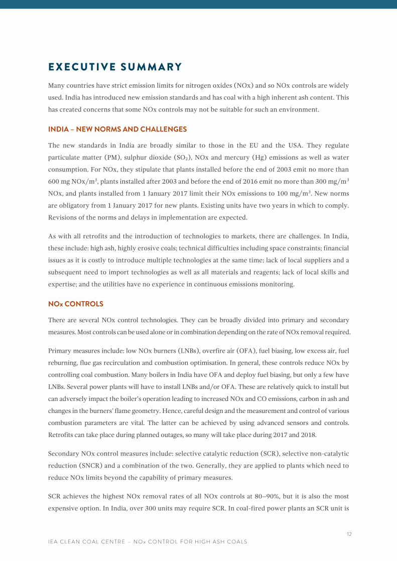
E X E C U T I V E S U M M A R Y
Many countries have strict emission limits for nitrogen oxides (NOx) and so NOx controls are widely
used. India has introduced new emission standards and has coal with a high inherent ash content. This
has created concerns that some NOx controls may not be suitable for such an environment.
INDIA – NEW NORMS AND CHALLENGES
The new standards in India are broadly similar to those in the EU and the USA. They regulate
particulate matter (PM), sulphur dioxide (SO2), NOx and mercury (Hg) emissions as well as water
consumption. For NOx, they stipulate that plants installed before the end of 2003 emit no more than
600 mg NOx/m3, plants installed after 2003 and before the end of 2016 emit no more than 300 mg/m3
NOx, and plants installed from 1 January 2017 limit their NOx emissions to 100 mg/m3. New norms
are obligatory from 1 January 2017 for new plants. Existing units have two years in which to comply.
Revisions of the norms and delays in implementation are expected.
As with all retrofits and the introduction of technologies to markets, there are challenges. In India,
these include: high ash, highly erosive coals; technical difficulties including space constraints; financial
issues as it is costly to introduce multiple technologies at the same time; lack of local suppliers and a
subsequent need to import technologies as well as all materials and reagents; lack of local skills and
expertise; and the utilities have no experience in continuous emissions monitoring.
NOx CONTROLS
There are several NOx control technologies. They can be broadly divided into primary and secondary
measures. Most controls can be used alone or in combination depending on the rate of NOx removal required.
Primary measures include: low NOx burners (LNBs), overfire air (OFA), fuel biasing, low excess air, fuel
reburning, flue gas recirculation and combustion optimisation. In general, these controls reduce NOx by
controlling coal combustion. Many boilers in India have OFA and deploy fuel biasing, but only a few have
LNBs. Several power plants will have to install LNBs and/or OFA. These are relatively quick to install but
can adversely impact the boiler’s operation leading to increased NOx and CO emissions, carbon in ash and
changes in the burners’ flame geometry. Hence, careful design and the measurement and control of various
combustion parameters are vital. The latter can be achieved by using advanced sensors and controls.
Retrofits can take place during planned outages, so many will take place during 2017 and 2018.
Secondary NOx control measures include: selective catalytic reduction (SCR), selective non-catalytic
reduction (SNCR) and a combination of the two. Generally, they are applied to plants which need to
reduce NOx limits beyond the capability of primary measures.
SCR achieves the highest NOx removal rates of all NOx controls at 80–90%, but it is also the most
expensive option. In India, over 300 units may require SCR. In coal-fired power plants an SCR unit is
I E A C L E A N C O A L C E N T R E – N O x C O N T R O L F O R H I G H A S H C O A L S
13
generally installed between the economiser and the air heater, where the temperature of the flue gas
is optimal for an SCR reaction. However, in this configuration, known as hot-side, high-dust, the SCR
is exposed to the fly ash and chemical components of the flue gas, which can cause excessive wear on:
the ductwork; large particle ash screens; ammonia injection grid (AIG) nozzles; flow distribution
devices; and the SCR catalyst. The ash also leads to poor distribution of velocity into the catalyst,
accelerates its deactivation, and increases costs of catalyst management. These issues can be mitigated
by appropriate design, such as the use of abrasion resistant coatings, erosion resistant wear plate, and
wear shields on AIG lances, proper reactor sizing, catalyst module shape and pitch size. Pilot tests are
currently underway (2017-18) on NTPC units to find the best solutions.
On its own, SNCR reduces NOx by 30–50%, while SCR levels of performance can be achieved if it is
applied in conjunction with other combustion controls. Historically, the effectiveness of SNCR has
been limited, especially in utility-scale boilers, due to a lack of accurate real-time tools to measure the
temperature and CO profile within the boiler – parameters which are important for an effective NOx
reduction reaction. However, recent developments in measurement systems allow the effective use of
SNCR even on large furnaces (>400 MW). In India, an SNCR would have to cover a greater area and
not all types of spraying nozzles will be applicable; this can be verified with CFD modelling and field
tests. In Indian applications it would be preferable to use urea as the reagent rather than ammonia, as
urea is non-toxic and its use would avoid various environmental and health hazards. Also, urea is much
more effective than ammonia on large furnaces, according to some experts. Current tests on NTPC
units will ascertain the applicability of SNCR.
As India is introducing emission standards for more pollutants, and pollution controls are expensive
and time consuming to install, which disrupts power generation, it would make sense to co-ordinate
installation of pollution control systems and to focus on multi-pollutant control systems. There are a
few multi-pollutant controls which can remove NOx. Some of them, such as ReACT™ have been used
in coal-fired power plants for several years. Some are deployed in non-coal applications but have the
potential to be applied to coal-fired plants and are in various stages of testing and demonstration.
CLOSING REMARKS
Choosing appropriate methods of NOx control for a power plant requires a site-specific strategy which
considers cost, performance and safety, and also water requirements.
NOx controls for high ash coals are broadly the same as for ‘normal’ boilers, but they must be
customised to local requirements as has already happened with LNBs.
There is a lack of SCR and SNCR commercial installations in India. However, the experience from high
ash lignite-fired plants and from high-dust industries such as cement kilns indicates their potential,
and vendors have confidence their systems will be applicable to Indian plants. However, utilities are
not expected to make decisions about SNCR and SCR until the test results from NTPC units are clear.
I N T R O D U C T I O N
I E A C L E A N C O A L C E N T R E – N O x C O N T R O L F O R H I G H A S H C O A L S
14
1 I N T R O D U C T I O N
Since the 1970s various technologies to control emissions of nitrogen oxides, (NOx) and sulphur
oxides (SOx) have been used in countries with relevant emission standards. However, this is not the
case in India, where there were no limits for these pollutants until January 2017. Instead, National
Ambient Air Quality Standards have been in place and minimum stack heights were specified to
disperse SO2 and NOx, while standards for the control of particulates were relatively lenient at 150
and 350 mg/m3 depending on the size and age of the plant (Sloss, 2015; Nalbandian-Sugden, 2015).
NOx emissions control legislation has been introduced in India where the majority of coals fired have
a high ash content. Thus, the control of NOx emissions from high ash coals is now of particular
relevance to India.
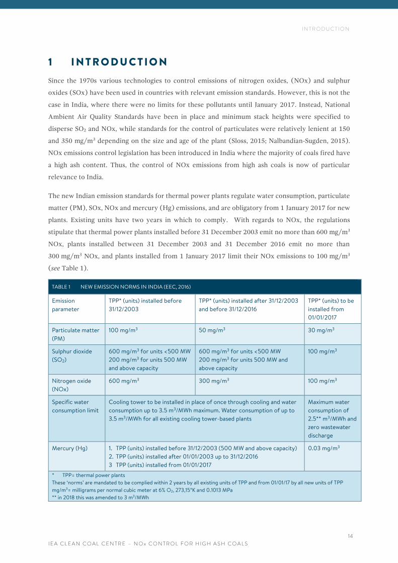
The new Indian emission standards for thermal power plants regulate water consumption, particulate
matter (PM), SOx, NOx and mercury (Hg) emissions, and are obligatory from 1 January 2017 for new
plants. Existing units have two years in which to comply. With regards to NOx, the regulations
stipulate that thermal power plants installed before 31 December 2003 emit no more than 600 mg/m3
NOx, plants installed between 31 December 2003 and 31 December 2016 emit no more than
300 mg/m3 NOx, and plants installed from 1 January 2017 limit their NOx emissions to 100 mg/m3
(see Table 1).
TABLE 1 NEW EMISSION NORMS IN INDIA (EEC, 2016)
Emission
parameter
TPP* (units) installed before
31/12/2003
TPP* (units) installed after 31/12/2003
and before 31/12/2016
TPP* (units) to be
installed from
01/01/2017
Particulate matter
(PM)
100 mg/m3 50 mg/m3 30 mg/m3
Sulphur dioxide
(SO2)
600 mg/m3 for units <500 MW
200 mg/m3 for units 500 MW
and above capacity
600 mg/m3 for units <500 MW
200 mg/m3 for units 500 MW and
above capacity
100 mg/m3
Nitrogen oxide
(NOx)
600 mg/m3 300 mg/m3 100 mg/m3
Specific water
consumption limit
Cooling tower to be installed in place of once through cooling and water
consumption up to 3.5 m3/MWh maximum. Water consumption of up to
3.5 m3/MWh for all existing cooling tower-based plants
Maximum water
consumption of
2.5** m3/MWh and
zero wastewater
discharge
Mercury (Hg) 1. TPP (units) installed before 31/12/2003 (500 MW and above capacity)
2. TPP (units) installed after 01/01/2003 up to 31/12/2016
3 TPP (units) installed from 01/01/2017
0.03 mg/m3
* TPP= thermal power plants
These ‘norms’ are mandated to be complied within 2 years by all existing units of TPP and from 01/01/17 by all new units of TPP
mg/m3= milligrams per normal cubic meter at 6% O2, 273,15°K and 0.1013 MPa
** in 2018 this was amended to 3 m3/MWh
I N T R O D U C T I O N
I E A C L E A N C O A L C E N T R E – N O x C O N T R O L F O R H I G H A S H C O A L S
15
In terms of NOx control in India, many boilers have overfire air (OFA) and deploy fuel biasing (BHEL,
2015; Nandakumar and others, 2008). But only a handful of units have primary NOx control measures
in the form of low NOx burners (LNBs) (Platts, 2016). There are no secondary NOx controls on any
units to date (March 2018). Consequently, utilities have limited experience of controlling NOx
emissions and will tend to rely on the expertise of equipment suppliers. This creates opportunities for
equipment manufacturers, as well as a need for global technology leaders to modify their products to
meet local market requirements, particularly for high ash content coal.
Indian thermal power plants fire mostly indigenous subbituminous coals and washery middlings
(Nandakumar, 2018). Indian coal has a relatively low moisture content. As reported by Barnes (2016),
three-quarters of current Indian coal production has an ash content of 30% or greater, with some of
the highest ash coals approaching 50%, whereas coal traded on the international market rarely exceeds
15% ash content. Much of the ash is inherent, which means that it is present as small particles of
mineral matter embedded in the combustible part of the coal, making it difficult to remove to levels
below 30% prior to combustion (Sloss, 2015; Barnes, 2016). Furthermore, ash in Indian coals has a
high percentage of abrasive and erosive solids including silica, aluminium oxide, and iron oxide, with
silica in alpha form being particularly erosive. Firing such high ash fuel can create many problems,
including increased fouling, which causes reduced heat transfer and erosion of heat transfer surfaces
in horizontal pass, second pass and downstream ducting and equipment. But, Indian utilities minimise
these detrimental effects by appropriate boiler design. Furnaces firing Indian coal are larger, both in
width and height than boilers firing imported coal; flue gas velocities are lower; and the sizing and
selection of various auxiliary systems can also differ (Mills, 2016; Arumugam, 2016). However, such
details are not the subject of this report and the interested reader is referred to another report from
the IEA CCC (Mills, 2016) and work by Arumugan (2016).
This report reviews available NOx controls for coal-fired units in general. Examples of recent
developments are given and systems are identified that could be successfully applied in Indian power
plants. The challenges facing Indian utilities are also considered.
C O A L Q U A L I T Y A N D N O x F O R M A T I O N
I E A C L E A N C O A L C E N T R E – N O x C O N T R O L F O R H I G H A S H C O A L S
16
2 C O A L Q U A L I T Y A N D N O x F O R M A T I O N
The two major influences on the formation of NOx in coal-fired power plants are the combustion
conditions and the properties of the coal.
2.1 COMBUSTION CONDITIONS
Combustion of coal releases the nitrogen bound in the organic matter as nitrogen oxides (NOx).
Conversion to NOx is incomplete and species such as nitrogen (N2), nitric oxide (NO), nitrogen
dioxide (NO2) and nitrous oxide (N2O) are among the possible products of a complex process
involving many different and competing reactions during combustion. The main coal properties that
affect the production of NOx are the volatile matter and the nitrogen content. NOx produced from the
coal nitrogen is known as the fuel NOx and is mainly NO. Fuel NOx formation is due to the oxidation
of the nitrogen intrinsically bound in the fuel which is converted to either N2 or NO depending on the
intermediate radical reactions and oxygen availability in the reaction regions. The conversion of fuel
nitrogen to NO is highly dependent on the local flame stoichiometry. Coal bound nitrogen ranges from
0.5–2% (weight %, dry, ash-free basis) and can contribute up to 70–80% of NOx formed during coal
combustion. Nitrogen is also a major component of the air used for combustion. At high temperatures
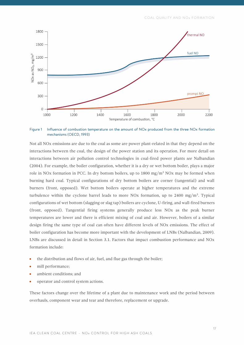
(>1000°C) this produces thermal NOx (OECD, 1993). Thermal NOx generally accounts for about
5–25% of the NOx formed during coal combustion. Prompt NOx occurs in the front of the burner
flame from reactions between the nitrogen in the air and the hydrocarbon fuel fragments before
they undergo either oxidation to NO or reduction to N2. The prompt NOx portion from coal
accounts for less than 5% of the total NOx emissions (Nalbandian, 2009). The influence of the
temperature of combustion on NOx formation is shown in Figure 1.
The formation of NOx emissions is less in fluidised bed combustion (FBC) than in pulverised coal
combustion (PCC). This is because the combustion takes place at lower temperatures (700–800°C)
than in PCC (1300–1700°C) (Lockwood, 2013). However, a disadvantage of FBC technology burning
coal is an increase in the formation of the greenhouse gas N2O, which is also due to the lower
combustion temperatures. NOx formation and emissions are discussed in various reports from the IEA
CCC including Wiatros-Motyka (2016a), Carpenter (2013), Minchener (2012), Sloss (2010, 2011) and
Nalbandian (2009).
C O A L Q U A L I T Y A N D N O x F O R M A T I O N
I E A C L E A N C O A L C E N T R E – N O x C O N T R O L F O R H I G H A S H C O A L S
17
Figure 1 Influence of combustion temperature on the amount of NOx produced from the three NOx formation
mechanisms (OECD, 1993)
Not all NOx emissions are due to the coal as some are power plant-related in that they depend on the
interactions between the coal, the design of the power station and its operation. For more detail on
interactions between air pollution control technologies in coal-fired power plants see Nalbandian
(2004). For example, the boiler configuration, whether it is a dry or wet bottom boiler, plays a major
role in NOx formation in PCC. In dry bottom boilers, up to 1800 mg/m3 NOx may be formed when
burning hard coal. Typical configurations of dry bottom boilers are corner (tangential) and wall
burners (front, opposed). Wet bottom boilers operate at higher temperatures and the extreme
turbulence within the cyclone barrel leads to more NOx formation, up to 2400 mg/m3. Typical
configurations of wet bottom (slagging or slag tap) boilers are cyclone, U-firing, and wall-fired burners
(front, opposed). Tangential firing systems generally produce less NOx as the peak burner
temperatures are lower and there is efficient mixing of coal and air. However, boilers of a similar
design firing the same type of coal can often have different levels of NOx emissions. The effect of
boiler configuration has become more important with the development of LNBs (Nalbandian, 2009).
LNBs are discussed in detail in Section 3.1. Factors that impact combustion performance and NOx
formation include:
• the distribution and flows of air, fuel, and flue gas through the boiler;
• mill performance;
• ambient conditions; and
• operator and control system actions.
These factors change over the lifetime of a plant due to maintenance work and the period between
overhauls, component wear and tear and therefore, replacement or upgrade.
C O A L Q U A L I T Y A N D N O x F O R M A T I O N
I E A C L E A N C O A L C E N T R E – N O x C O N T R O L F O R H I G H A S H C O A L S
18
2.2 IMPACT OF COAL PROPERTIES ON NOx EMISSIONS
In an in-depth study Davidson (2000) found that the influence of coal properties on NOx emissions,
despite intensive research efforts, was not sufficiently well-defined to allow the prediction of NOx
emission levels from coal properties alone, and this remains the case. As described in the previous
section, many factors influence NOx formation. Among these, the roles and interaction of factors such
as nitrogen partitioning between the volatiles and chars, nitrogen functionality, coal rank, coal
nitrogen and volatile content in the formation of NOx remain uncertain. Combustion conditions are
extremely important as even small changes in operating parameters may have a similar or greater
impact than the fuel parameters. As such, correlating data from plants with different combustion
conditions should not only be avoided but also treated as distinct data sets. Davidson (2000) concluded
that due to the complexity of the NOx formation process and its dependence on site specific
combustion conditions, successful prediction of NOx emissions should be based on changes in NOx
emissions relative to a baseline resulting from coal property changes. A prediction might be based on
coal properties measured by standard and/or advanced analytical methods as well as models. Although
these tools continue to be found useful, it seems unlikely that absolute NOx levels can be predicted
with confidence. Hence, source testing is the best way to determine NOx emissions.
The main properties of a coal that influence the firing system design are its volatile matter, grindability
(assessed using the Hardgrove Index), ash content, moisture, net calorific value, nitrogen content and
ash analysis. Significant variation in coal properties may necessitate an adjustment of the operating
conditions of the firing system and the mills. Both hard/bituminous and lignite/subbituminous coals
may have a high ash content, which can impact on the operational performance of a power plant.
During combustion, significant energy may be required to raise the temperature of the ash, in some
cases above its melting point, which affects the efficiency of the whole process.
Firing high ash, low heat value coal means that more coal is burnt for the same electrical output, which
can lead to an increase in emissions of several pollutants such as SO2, NOx and CO2. Therefore,
removing as much ash as possible prior to combustion can improve efficiency. There are many ways
to prepare coal to improve the quality, such as wet cleaning processes, dense-medium separation, dry
coal cleaning, and chemical and biological cleaning technologies. These processes have been reviewed
by the IEA CCC in reports such as Reid (2017), and Dong (2011), and others including Gupta (2016);
Saini and Srivastava (2016); Venugopal and others (2016); Xia and others (2016); Meshram and others
(2015); Mishra and others (2015); CPSI (2015); Zhang and others (2014); Zhao and others (2014);
Charan and others (2011); Burnard and Bhattacharya (2011); Zamuda and Sharpe (2007).
Pillai and others (2016) studied the effect of coal properties, including high ash content on the
performance of 500 MW boilers in Indian, coal-fired power plants. The interested reader is referred
to this reference for more detail.
C O A L Q U A L I T Y A N D N O x F O R M A T I O N
I E A C L E A N C O A L C E N T R E – N O x C O N T R O L F O R H I G H A S H C O A L S
19
2.3 INDIA
Total proven coal reserves in India amount to 87 billion tonnes, equivalent to about 140 years of
current output, of which 95% is hard coal (steam and coking coal), and the remainder is lignite. Total
coal resources, both inferred and indicated, including deposits that are yet to be proven, are almost
two-and-a-half-times larger, at 213 billion tonnes. The majority of the coal is found in the east of the
country. India ranks third in world coal production, producing 764 Mt of coal in 2015, a growth of 14%
compared to 2014 (668 Mt) (Enerdata, 2016). India and its power sector are on a growth path and
electricity demand is expected to increase from 776 TWh in 2012 to 2499 TWh by 2030 (Mazumder,
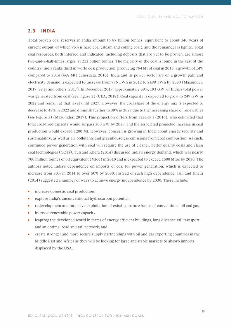
2017; Setty and others, 2017). In December 2017, approximately 58%, 193 GW, of India’s total power
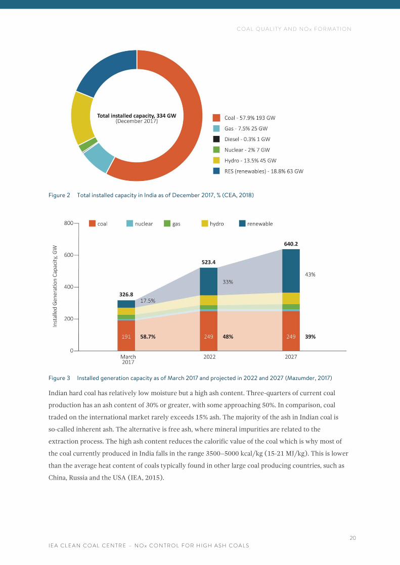
was generated from coal (see Figure 2) (CEA, 2018). Coal capacity is expected to grow to 249 GW in
2022 and remain at that level until 2027. However, the coal share of the energy mix is expected to
decrease to 48% in 2022 and diminish further to 39% in 2027 due to the increasing share of renewables
(see Figure 3) (Mazumder, 2017). This projection differs from Feerick’s (2016), who estimated that
total coal-fired capacity would surpass 300 GW by 2030, and the associated projected increase in coal
production would exceed 1200 Mt. However, concern is growing in India about energy security and
sustainability, as well as air pollutants and greenhouse gas emissions from coal combustion. As such,
continued power generation with coal will require the use of cleaner, better quality coals and clean
coal technologies (CCTs). Tuli and Khera (2014) discussed India’s energy demand, which was nearly
700 million tonnes of oil equivalent (Mtoe) in 2010 and is expected to exceed 1500 Mtoe by 2030. The
authors noted India’s dependence on imports of coal for power generation, which is expected to
increase from 30% in 2014 to over 50% by 2030. Instead of such high dependence, Tuli and Khera
(2014) suggested a number of ways to achieve energy independence by 2030. These include:
• increase domestic coal production;
• explore India’s unconventional hydrocarbon potential;
• redevelopment and intensive exploitation of existing mature basins of conventional oil and gas,
• increase renewable power capacity,
• leapfrog the developed world in terms of energy efficient buildings, long distance rail transport,
and an optimal road and rail network; and
• create stronger and more secure supply partnerships with oil and gas exporting countries in the
Middle East and Africa as they will be looking for large and stable markets to absorb imports
displaced by the USA.
C O A L Q U A L I T Y A N D N O x F O R M A T I O N
I E A C L E A N C O A L C E N T R E – N O x C O N T R O L F O R H I G H A S H C O A L S
20
Figure 2 Total installed capacity in India as of December 2017, % (CEA, 2018)
Figure 3 Installed generation capacity as of March 2017 and projected in 2022 and 2027 (Mazumder, 2017)
Indian hard coal has relatively low moisture but a high ash content. Three-quarters of current coal
production has an ash content of 30% or greater, with some approaching 50%. In comparison, coal
traded on the international market rarely exceeds 15% ash. The majority of the ash in Indian coal is
so-called inherent ash. The alternative is free ash, where mineral impurities are related to the
extraction process. The high ash content reduces the calorific value of the coal which is why most of
the coal currently produced in India falls in the range 3500–5000 kcal/kg (15-21 MJ/kg). This is lower
than the average heat content of coals typically found in other large coal producing countries, such as
China, Russia and the USA (IEA, 2015).
C O A L Q U A L I T Y A N D N O x F O R M A T I O N
I E A C L E A N C O A L C E N T R E – N O x C O N T R O L F O R H I G H A S H C O A L S
21
The high ash content of Indian coal has several effects (Cornot-Gandolphe, 2016):
• it lowers power plant efficiency in various ways including ash hampering heat transmission;
• plant operation and maintenance (O&M) are generally more difficult due to the need to remove
more fly and bottom ash;
• it can lead to higher levels of pollutant emissions;
• lower efficiencies lead to higher CO2 emissions;
• the higher volume of high ash coal necessary per unit of energy content increases transportation
costs as well as pollution; and
• the coal and ash properties dictate critical aspects of boiler design and equipment selection for a
power plant. For example, the high ash content of Indian coal means that a longer residence time
in the boiler is needed for the carbon to burn out, so the boilers need to be ~20% larger than
those running on lower-ash coal.
The typical nitrogen content of Indian coal varies from 2.3 to 2.6 kg/Mcal (0.55–0.62 kg/MJ)
which is slightly higher than the nitrogen content of North American coals – 2.08 to 2.45 kg/Mcal
(0.50–0.59 kg/MJ) (Raj and others, nd). Indian boilers firing high ash coals are bigger than those in
Europe or North America. The increased furnace volume corresponds to lower volumetric heat
loading and therefore lower furnace temperatures, which result in NOx emissions in the order of
300-500 ppm. In an attempt to reduce the transport of high ash coal, regulations were adopted in
2012, that mandated that power stations located more than 1000 km from coal mines, and those
located in sensitive and urban areas, use coal containing not more than 34% ash on a quarterly
average basis. The distance was reduced to 500 km in June 2016. Under a January 2015 amendment
to the Environment Protection Rules 2014, coal producers and suppliers are also responsible for
ensuring that coal with an ash content not exceeding 34% is supplied to the power plants
(Cornot-Gandolphe, 2016). The expectation is that more coal preparation plants will be built near
the mines. Coal beneficiation, such as cleaning, preparation, handling and, washing can improve the
quality of Indian run of mine (ROM) coal. This is usually done by crushing the coal and putting it in
a liquid to separate the lighter coal (low ash content) from the heavier coal (high ash content) and
the extraneous material. Washing the coal increases its calorific value and consequently its worth. It
also gives it a more consistent and improved quality, and as such increases its energy efficiency during
combustion, reduces the size of the boiler unit, reduces wear and tear as extraneous material is removed,
and reduces the amount of the fly ash by-product. In addition, transportation of the cleaned coal is more
efficient. For more detail on coal beneficiation see the IEA CCC report by Reid (2017).
Despite these benefits, Cornot-Gandolphe (2016) found that little coal is actually washed in India. The
cost of washing, estimated at approximately 5 US$/t is considered too high. In addition, Indian coals
wash poorly due to their high inherent ash content. In 2016, less than 20% of the coal produced was
washed, compared to a global average of more than 50%. And most of the coal that is washed in India

C O A L Q U A L I T Y A N D N O x F O R M A T I O N
I E A C L E A N C O A L C E N T R E – N O x C O N T R O L F O R H I G H A S H C O A L S
22
is coking coal. The capacity of coal washing facilities for steam coal is around 91 Mt/y. Although the
utilisation rate of washeries is currently low, it is expected to change in the coming years as India plans
to make coal washing mandatory.
P R I M A R Y M E A S U R E S F O R N O x C O N T R O L
I E A C L E A N C O A L C E N T R E – N O x C O N T R O L F O R H I G H A S H C O A L S
23
3 P R I M A R Y M E A S U R E S F O R N O x C O N T R O L
Available NOx removal technologies can be broadly divided into two main categories: primary or
combustion measures and post-combustion or flue gas control systems. Most controls can be used
alone or in combination with other systems depending on the required rate of NOx removal. There
are a number of NOx control technologies available commercially, detailed operational principles of
which are described in an IEA CCC report by Nalbandian (2009). In this chapter, the primary measures
for NOx control are reviewed, and then the focus is turned to those which are particularly appropriate
for high ash coals.
3.1 LOW NOx BURNERS (LNBs)
Low NOx burners are a well proven, mature technology that has been used in countries with relevant
standards for over thirty years (Wiatros-Motyka, 2016b; Balasubramanian and others, 2015; Miller,
2005). LNBs use internal air staging to control the mixture of fuel and air. This reduces peak flame
temperatures and results in less formation of NOx. In LNBs the initial fuel combustion occurs in a
fuel-rich, oxygen deficient zone. The formation of NOx is suppressed as oxygen molecules are not
available to react with nitrogen released from coal and therefore present in the air. This is followed by
a reducing atmosphere where hydrocarbons react with NOx to turn it into molecular nitrogen (N2).
After the primary combustion zone, the air required to complete combustion of coal is added, and the
temperature is sufficiently low so that additional NOx formation is minimised.
All LNBs work on the principle of staging combustion air within the burner to reduce NOx formation,
but designs vary widely between manufacturers, who often offer more than one version of burners
depending on the application.
LNBs typically achieve 30–50% NOx reduction on their own, whereas when in combination with other
primary measures they can achieve reductions of around 80% (Xu and others, 2015). Their
performance depends on various factors including the furnace arrangements, fuel quality and
operating conditions. For example, larger reductions of NOx can be achieved for highly volatile coals
(Balasubramanian and others, 2015).
Although in some instances, space restrictions may limit retrofits of LNBs or ultra-LNBs, they are
relatively easy to install. However, it must be done with consideration of their impact on combustion
and boiler operating conditions. One concern about LNBs is their potential to reduce combustion
efficiency, which leads to a higher level of unburnt carbon in the fly ash and emissions of CO. Increased
carbon in fly ash lowers its resistivity which can reduce the efficiency of particulate control in
electrostatic precipitators (ESP). Elevated levels of unburnt carbon in fly ash can also impact the
saleability of the ash. The actual impact on levels of unburnt carbon from retrofitting LNBs varies
between units, depending on many factors such as the age and condition of the plant, the furnace
arrangement and coal properties. However, there are various measures to mitigate the impact of
P R I M A R Y M E A S U R E S F O R N O x C O N T R O L
I E A C L E A N C O A L C E N T R E – N O x C O N T R O L F O R H I G H A S H C O A L S
24
unburnt carbon including reducing the size of coal particles, controlling the air:fuel ratio and velocity
to individual burners and the use of advanced control systems. This is the subject of another IEA CCC
report by Wiatros-Motyka (2016a).
3.2 OVERFIRE AIR (AIR STAGING)
The simplest method to reduce fuel NOx is to limit the availability of oxygen in the near burner area,
according to Balasubramanian and others (2015). When this is carried out for the whole furnace it is
known as two stage combustion or air staging. One technique to stage combustion is to install
secondary and even tertiary overfire air ports above the main combustion zone (Miller, 2005). Furnace
overfire air technology divides combustion air into two separate streams, extending the principle of
low NOx burners to the furnace volume rather than purely the near burner region. A primary flow, of
70–90% of the total combustion air, is routed to the burners, while a secondary flow of the remaining
combustion air is injected above the burner elevation. This allows two-stage combustion. In the first
stage, the air flow to the burner is mixed with the fuel at the burner, producing an oxygen deficient,
fuel rich zone. This results in minimised formation of fuel NOx and partial combustion of the fuel.
During the second stage, the balance of the combustion air is injected through the OFA nozzles into
the furnace, where combustion is completed (Xu and others, 2015). Two stage combustion in
combination with an overall lower level of excess oxygen reduces the net unit heat rate as well as SO3,
CO and loss on ignition (LOI) (or unburnt carbon), and produces a more uniform temperature profile
at the furnace exit.
The location of the injection ports and mixing of the OFA are critical to maintain efficient combustion.
The relatively low temperature of the secondary stage limits the production of thermal NOx. Air
staging in the furnace does not increase the energy consumption of the combustion plant and does not
have any adverse effects on its operational availability. Retrofitting OFA on an existing boiler can be
costly as it involves water wall tube modifications to create the ports for the secondary air nozzles and
the addition of ducts, dampers and the windbox/air ports. In addition, the design of the system differs
depending on the boiler configuration.
Balasubramanian and others (2015) consider that in retrofit installations 10–20% of the total
combustion air is used as OFA. The OFA amount is limited by existing furnace constraints on residence
time for maximum burnout. Due to these constraints, the retrofit of an OFA system tends to lead to a
compromise between NOx reduction and LOI. The latter strongly depends on boiler configuration.
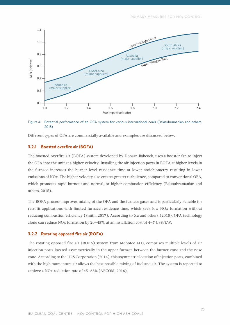
The expected performance of an OFA system for various international coals is shown in Figure 4. In
the case of Indian coals, with a higher inert/non-combustibles content than North American
Carboniferous coals, the primary air requirement is higher, at a ratio of more than 2.0 for transport of
coal from mill to burners. These ratios are similar to Australian and South African coals (Nandakumar,
2018).
P R I M A R Y M E A S U R E S F O R N O x C O N T R O L
I E A C L E A N C O A L C E N T R E – N O x C O N T R O L F O R H I G H A S H C O A L S
25
Figure 4 Potential performance of an OFA system for various international coals (Balasubramanian and others,
2015)
Different types of OFA are commercially available and examples are discussed below.
3.2.1 Boosted overfire air (BOFA)
The boosted overfire air (BOFA) system developed by Doosan Babcock, uses a booster fan to inject
the OFA into the unit at a higher velocity. Installing the air injection ports in BOFA at higher levels in
the furnace increases the burner level residence time at lower stoichiometry resulting in lower
emissions of NOx. The higher velocity also creates greater turbulence, compared to conventional OFA,
which promotes rapid burnout and normal, or higher combustion efficiency (Balasubramanian and
others, 2015).
The BOFA process improves mixing of the OFA and the furnace gases and is particularly suitable for
retrofit applications with limited furnace residence time, which seek low NOx formation without
reducing combustion efficiency (Smith, 2017). According to Xu and others (2015), OFA technology
alone can reduce NOx formation by 20–45%, at an installation cost of 4–7 US$/kW.
3.2.2 Rotating opposed fire air (ROFA)
The rotating opposed fire air (ROFA) system from Mobotec LLC, comprises multiple levels of air
injection ports located asymmetrically in the upper furnace between the burner zone and the nose
cone. According to the URS Corporation (2014), this asymmetric location of injection ports, combined
with the high momentum air allows the best possible mixing of fuel and air. The system is reported to
achieve a NOx reduction rate of 45–65% (AECOM, 2016).
P R I M A R Y M E A S U R E S F O R N O x C O N T R O L
I E A C L E A N C O A L C E N T R E – N O x C O N T R O L F O R H I G H A S H C O A L S
26
3.3 FUEL REBURNING (STAGING)
Reburning is a staged combustion process in which fuel is burned in three zones, namely the primary
combustion zone, reburn zone and burnout zone. In the primary zone, coal is fired through
conventional or low NOx burners generally in low excess air conditions to reduce initial NOx
formation. Then in the reburn zone a secondary fuel is injected or blown into the upper section of the
furnace. The secondary reburn fuel, whether coal, oil, gas, biomass or a coal-water mixture is used as
a reducing agent to convert NOx to N2. In coal combustion, low nitrogen containing fuels such as
natural gas, most often, or biomass, are used as the reburn fuel. However, coal and synthesis gas have
also been used. The main purpose is to provide effective mixing of the natural gas with the bulk flue
gas in the reburn zone. This zone has sub-stoichiometric conditions, without combustion air.
The secondary fuel breaks down to produce hydrocarbon fragments, which react with the NOx
produced in the primary combustion zone and reduce it to atmospheric nitrogen. In the third, burnout
zone, the gases exiting the reburn zone undergo additional combustion with overfire air. This stage is
essential to consume the CO and unburnt hydrocarbons leaving the reburn zone (IEA CCC, nd).
Fuel reburning does not require modifications to the existing main combustion system and can be used
on wall-, tangential- and cyclone-fired boilers (Miller, 2005). On its own it can typically achieve a
15-30% NOx reduction rate. It is often combined with LNB and OFA for greater rates of NOx removal
(Xu and others, 2015). Higher removal rates of up to 70% can also be achieved when using reburn
fuels other than coal, but the cost of the secondary fuel must be taken into account, as it may influence
the operating costs considerably (IEA CCC, nd).
The advantages of this technique include its flexibility as a variety of reburn fuels can be used and its
ability to operate over a wide range of NOx reduction values. Concerns regarding the use of this
technology are similar to those for other combustion modification processes. They include:
incomplete combustion leading to CO and hydrocarbon production and elevated levels of unburnt
carbon in the fly ash; changes in slagging and fouling characteristics; different ash properties and fly
ash loading, corrosion of boiler water tubes in a reducing atmosphere, higher fan power; and milling
constraints if coal is used as a reburn fuel (Miller, 2005).
3.4 FLUE GAS RECIRCULATION (FGR)
In flue gas recirculation, up to 20% of the flue gas is circulated back into the furnace or burners. This
modifies conditions in the combustion zone by lowering the peak flame temperature and the oxygen
concentration, so less thermal NOx is formed. In conventional applications (gas- and oil-fired boilers),
FGR recirculates 20–30% of the boiler flue gas from either the air heater inlet (hot FGR) or the ID
(induced draught) fan outlet (cold FGR) into the furnace. However, in coal-fired plants, the FGR can
have an impact on the thermal performance of the boiler. Nevertheless, FGR can be injected elsewhere
and, used as a reheat steam temperature control measure, it can offer additional NOx reduction
(Xu and others, 2015).
P R I M A R Y M E A S U R E S F O R N O x C O N T R O L
I E A C L E A N C O A L C E N T R E – N O x C O N T R O L F O R H I G H A S H C O A L S
27
Although the technique is used mainly in LNBs in gas-fired plants it has also been used commercially
for many years on coal-fired boilers, and has achieved reduction rates of typically less than 20%, due
to the relatively low contribution of thermal NOx to total NOx formation (Miller, 2005). The measure
is one of the least costly to retrofit as an installation cost of cost of 3–5 US$/kW has been reported. It
may also result in increased O&M requirements and is not widely used in coal-fired plants (Xu and
others, 2015).
3.5 FUEL BIASING
Fuel biasing is a relatively simple combustion control technique for achieving up to 20% NOx
reduction. It diverts fuel from the upper level burners to the lower ones to create a fuel rich lower
zone where NOx is reduced, and a fuel lean upper zone to complete CO burnout. The total amount of
coal supplied to the boiler remains the same as before fuel biasing. The exact amount of fuel delivered
to the upper burners depends on the unit load with better results achieved at lower loads. The extent
of the fuel biasing that can be implemented depends on the design of the burners and the pulverisers’
capacity (Bell and Buckingham, nd). Fuel biasing is frequently used as a retrofit measure in existing
installations with vertical boilers.
3.6 LOW EXCESS AIR (LEA)
Low excess air is the simplest NOx combustion control strategy and it offers a modest reduction
potential of 1–15% (Miller, 2005). It decreases the excess air in the combustion flame zone which in
turn limits fuel and thermal NOx formation. It also improves combustion efficiency and limits the
production of smoke, CO emissions, and minimises fouling and corrosion in the boiler. Although
oxygen measurement is useful to assess excess oxygen, to trim the excess oxygen set-point and to
adjust the air: fuel flow, it can be affected by air ingress into the boiler. Therefore, it should always be
accompanied by CO monitoring, which is considered the most sensitive and accurate indicator of
incomplete combustion (Lockwood, 2015). Moreover, due to the fact that the flue gas in the
convective pass is relatively ‘stratified’ as individual columns emitted by each burner, localised regions
of high CO and O2 can be present even in the economiser exit. Hence, it is of paramount importance
that oxygen and CO measurements should be performed in multiple locations by sensors deployed in
a grid configuration. Only then can the excess air be accurately controlled. The latest technologies
helpful in decreasing LEA are described in IEA CCC reports by Lockwood (2015) and Wiatros-Motyka
(2016a).
3.7 COMBUSTION OPTIMISATION
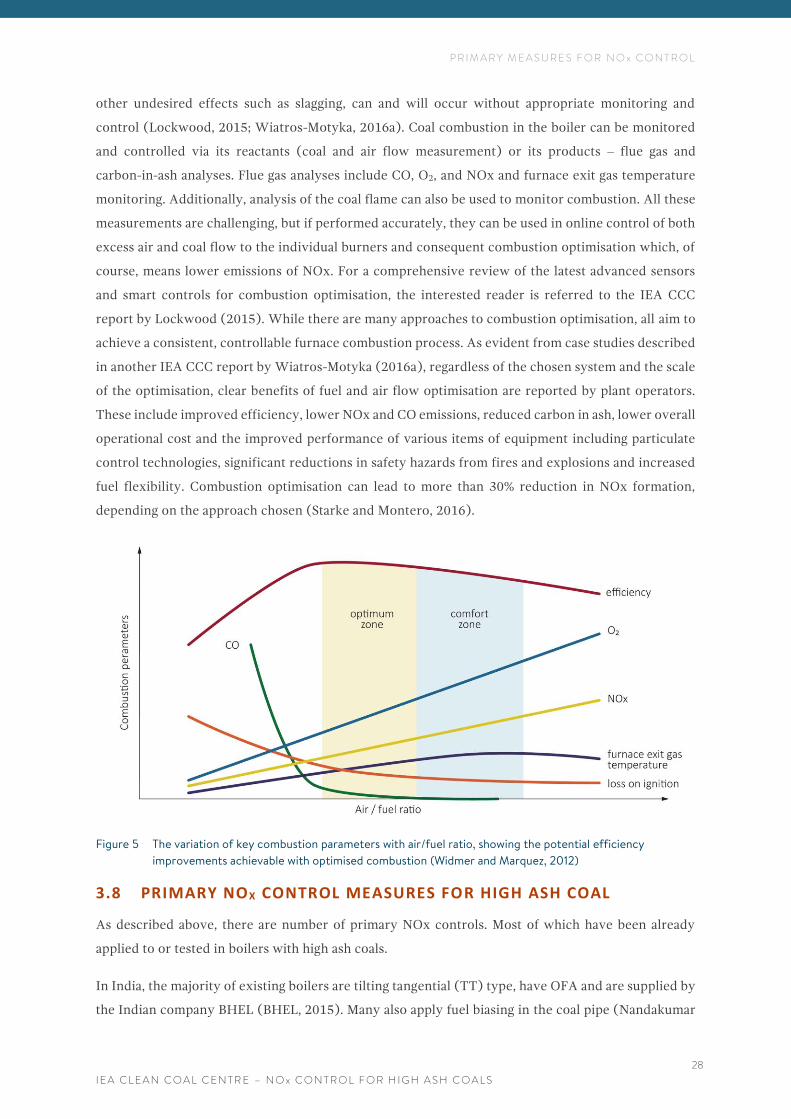
Key combustion parameters (NOx, O2, CO, LOI and boiler efficiency) vary depending on the air:fuel
ratio, as seen in Figure 5. However, maintaining the air:fuel ratio in the narrow optimum combustion
zone can be especially challenging for large multi-burner low NOx furnaces. These boilers are subject
to frequent load changes, and hence localised areas or transient periods of incomplete combustion.
This means that consequent increases in NOx, CO and LOI, and exit furnace temperature, as well as
P R I M A R Y M E A S U R E S F O R N O x C O N T R O L
I E A C L E A N C O A L C E N T R E – N O x C O N T R O L F O R H I G H A S H C O A L S
28
other undesired effects such as slagging, can and will occur without appropriate monitoring and
control (Lockwood, 2015; Wiatros-Motyka, 2016a). Coal combustion in the boiler can be monitored
and controlled via its reactants (coal and air flow measurement) or its products ‒ flue gas and
carbon-in-ash analyses. Flue gas analyses include CO, O2, and NOx and furnace exit gas temperature
monitoring. Additionally, analysis of the coal flame can also be used to monitor combustion. All these
measurements are challenging, but if performed accurately, they can be used in online control of both
excess air and coal flow to the individual burners and consequent combustion optimisation which, of
course, means lower emissions of NOx. For a comprehensive review of the latest advanced sensors
and smart controls for combustion optimisation, the interested reader is referred to the IEA CCC
report by Lockwood (2015). While there are many approaches to combustion optimisation, all aim to
achieve a consistent, controllable furnace combustion process. As evident from case studies described
in another IEA CCC report by Wiatros-Motyka (2016a), regardless of the chosen system and the scale
of the optimisation, clear benefits of fuel and air flow optimisation are reported by plant operators.
These include improved efficiency, lower NOx and CO emissions, reduced carbon in ash, lower overall
operational cost and the improved performance of various items of equipment including particulate
control technologies, significant reductions in safety hazards from fires and explosions and increased
fuel flexibility. Combustion optimisation can lead to more than 30% reduction in NOx formation,
depending on the approach chosen (Starke and Montero, 2016).
Figure 5 The variation of key combustion parameters with air/fuel ratio, showing the potential efficiency
improvements achievable with optimised combustion (Widmer and Marquez, 2012)
3.8 PRIMARY NOX CONTROL MEASURES FOR HIGH ASH COAL
As described above, there are number of primary NOx controls. Most of which have been already
applied to or tested in boilers with high ash coals.
In India, the majority of existing boilers are tilting tangential (TT) type, have OFA and are supplied by
the Indian company BHEL (BHEL, 2015). Many also apply fuel biasing in the coal pipe (Nandakumar
P R I M A R Y M E A S U R E S F O R N O x C O N T R O L
I E A C L E A N C O A L C E N T R E – N O x C O N T R O L F O R H I G H A S H C O A L S
29
and others, 2008). However, by the end of 2016, only twenty-four units had LNBs installed (Platts,
2016). Because of the new emission standards, it has been recommended that primary NOx controls
are retrofitted during the next outages, starting with the newest units. Hence, retrofits are expected
on a large scale (NRPC, 2017). Although there is a choice of primary measures, LNBs and OFA are the
most commonly used. A number of manufacturers offer these systems, some of which are specifically
designed for the Indian market.
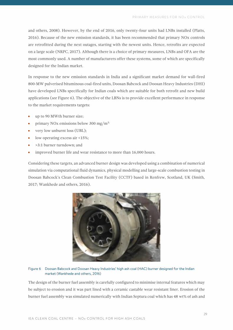
In response to the new emission standards in India and a significant market demand for wall-fired
800-MW pulverised bituminous coal-fired units, Doosan Babcock and Doosan Heavy Industries (DHI)
have developed LNBs specifically for Indian coals which are suitable for both retrofit and new build
applications (see Figure 6). The objective of the LBNs is to provide excellent performance in response
to the market requirements targets:
• up to 90 MWth burner size;
• primary NOx emissions below 300 mg/m3;
• very low unburnt loss (UBL);
• low operating excess air <15%;
• >3:1 burner turndown; and
• improved burner life and wear resistance to more than 16,000 hours.
Considering these targets, an advanced burner design was developed using a combination of numerical
simulation via computational fluid dynamics, physical modelling and large-scale combustion testing in
Doosan Babcock’s Clean Combustion Test Facility (CCTF) based in Renfrew, Scotland, UK (Smith,
2017; Wankhede and others, 2016).
Figure 6 Doosan Babcock and Doosan Heavy Industries’ high ash coal (HAC) burner designed for the Indian
market (Wankhede and others, 2016)
The design of the burner fuel assembly is carefully configured to minimise internal features which may
be subject to erosion and it was part lined with a ceramic castable wear resistant liner. Erosion of the
burner fuel assembly was simulated numerically with Indian Septura coal which has 48 wt% of ash and
P R I M A R Y M E A S U R E S F O R N O x C O N T R O L
I E A C L E A N C O A L C E N T R E – N O x C O N T R O L F O R H I G H A S H C O A L S
30
one of the highest propensities to cause erosion of any Indian coal. Wear patterns were qualitatively
validated by physical simulation on a two-phase model.
Physical combustion tests were carried out for various loads with different primary air:fuel ratios and
burner zone stoichiometry (BZS). The results showed:
• excellent performance under deep staged conditions and NOx emissions to meet the
<300 mg/m3 target;
• low burner pressure drop allowing minimum parasitic auxiliary power consumption; and
• good flame stability and flame rooting over turn-down range of >3:1 (Smith, 2017; Wankhede
and others, 2016; Smith and others, 2016).
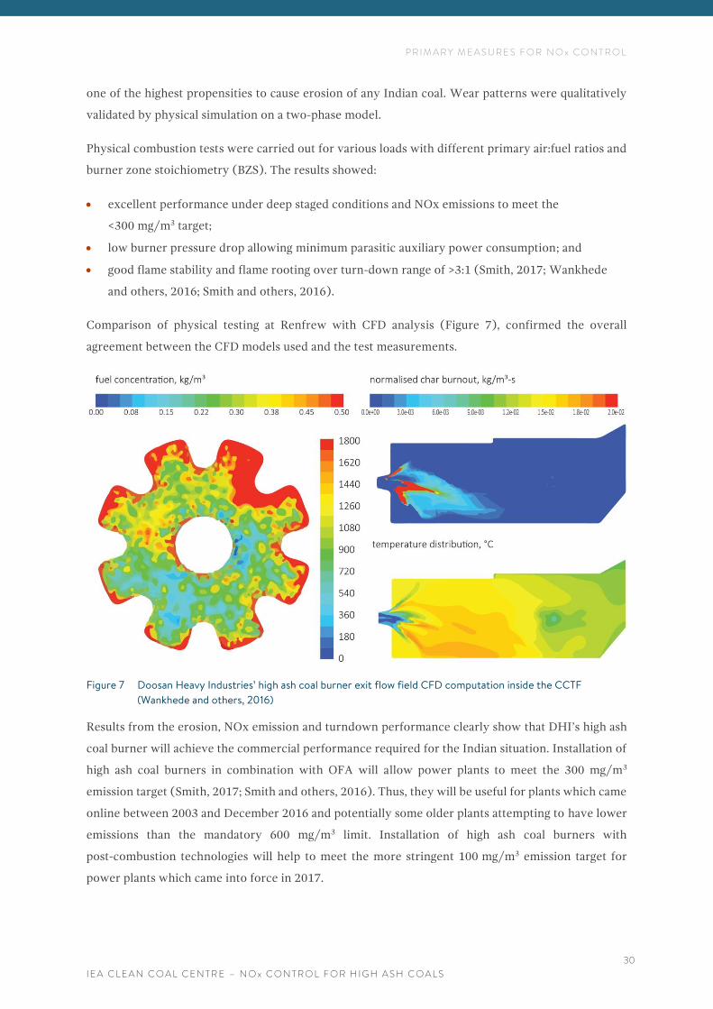
Comparison of physical testing at Renfrew with CFD analysis (Figure 7), confirmed the overall
agreement between the CFD models used and the test measurements.
Figure 7 Doosan Heavy Industries’ high ash coal burner exit flow field CFD computation inside the CCTF
(Wankhede and others, 2016)
Results from the erosion, NOx emission and turndown performance clearly show that DHI’s high ash
coal burner will achieve the commercial performance required for the Indian situation. Installation of
high ash coal burners in combination with OFA will allow power plants to meet the 300 mg/m3
emission target (Smith, 2017; Smith and others, 2016). Thus, they will be useful for plants which came
online between 2003 and December 2016 and potentially some older plants attempting to have lower
emissions than the mandatory 600 mg/m3 limit. Installation of high ash coal burners with
post-combustion technologies will help to meet the more stringent 100 mg/m3 emission target for
power plants which came into force in 2017.
P R I M A R Y M E A S U R E S F O R N O x C O N T R O L
I E A C L E A N C O A L C E N T R E – N O x C O N T R O L F O R H I G H A S H C O A L S
31
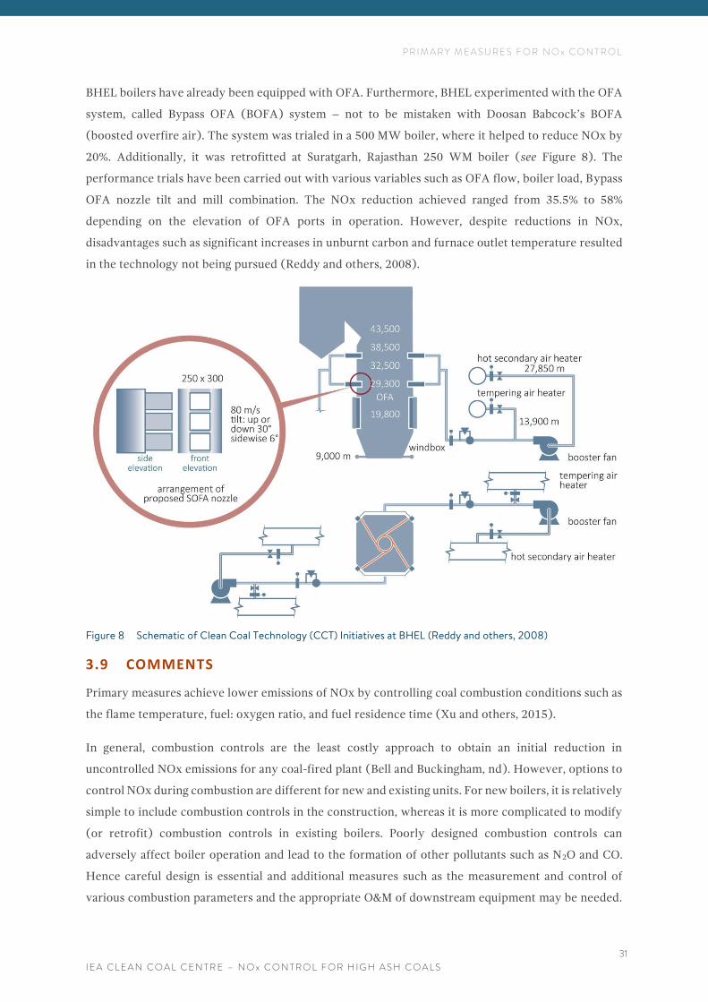
BHEL boilers have already been equipped with OFA. Furthermore, BHEL experimented with the OFA
system, called Bypass OFA (BOFA) system – not to be mistaken with Doosan Babcock’s BOFA
(boosted overfire air). The system was trialed in a 500 MW boiler, where it helped to reduce NOx by
20%. Additionally, it was retrofitted at Suratgarh, Rajasthan 250 WM boiler (see Figure 8). The
performance trials have been carried out with various variables such as OFA flow, boiler load, Bypass
OFA nozzle tilt and mill combination. The NOx reduction achieved ranged from 35.5% to 58%
depending on the elevation of OFA ports in operation. However, despite reductions in NOx,
disadvantages such as significant increases in unburnt carbon and furnace outlet temperature resulted
in the technology not being pursued (Reddy and others, 2008).
Figure 8 Schematic of Clean Coal Technology (CCT) Initiatives at BHEL (Reddy and others, 2008)
3.9 COMMENTS
Primary measures achieve lower emissions of NOx by controlling coal combustion conditions such as
the flame temperature, fuel: oxygen ratio, and fuel residence time (Xu and others, 2015).
In general, combustion controls are the least costly approach to obtain an initial reduction in
uncontrolled NOx emissions for any coal-fired plant (Bell and Buckingham, nd). However, options to
control NOx during combustion are different for new and existing units. For new boilers, it is relatively
simple to include combustion controls in the construction, whereas it is more complicated to modify
(or retrofit) combustion controls in existing boilers. Poorly designed combustion controls can
adversely affect boiler operation and lead to the formation of other pollutants such as N2O and CO.
Hence careful design is essential and additional measures such as the measurement and control of
various combustion parameters and the appropriate O&M of downstream equipment may be needed.
P R I M A R Y M E A S U R E S F O R N O x C O N T R O L
I E A C L E A N C O A L C E N T R E – N O x C O N T R O L F O R H I G H A S H C O A L S
32
The latter can be achieved using advanced sensors and controls as these allow accurate real-time
mapping of the furnace conditions and their consequent control.
Currently, low NOx burners are a standard NOx control technology used in countries with relevant
emission norms (Wiatros-Motyka, 2016b). In combination with other primary measures such as
overfire air, they can achieve a significant NOx emission reduction of up to 81% (Xu and others, 2015).
However, low NOx burners require precise fuel and air control to maintain uniform and efficient
combustion. Precise control is only possible when accurate, reliable and real-time measurements of all
air (primary, secondary and tertiary) and fuel flows are taken at each burner. Hence it is important to
understand the potential for changes in boiler performance when several other modifications are
implemented together.
New legislation in India means that all existing power plants must retrofit primary NOx controls in the
form of LNBs and most likely OFA too. Although not many, LNBs have been in operation in India since
1992, thus proving that they are able to operate in a high-ash environment. LNBs installed to date have
been supplied by several manufacturers (Platts, 2016). However, there is now a wider choice available.
Furthermore, manufacturers such as Doosan Babcock and Doosan Heavy Industries, who have already
had their technology installed in India, have recently developed new LNBs to address the specific
requirements of the Indian market. Finally, retrofitting primary measures such as OFA and LNB is
relatively simple and quick so it can take place during planned outages, as has been already
recommended to the utilities by the Indian Government.
S E L E C T I V E C A T A L Y T I C R E D U C T I O N ( S C R )
I E A C L E A N C O A L C E N T R E – N O x C O N T R O L F O R H I G H A S H C O A L S
33
4 S E L E C T I V E C A T A L Y T I C R E D U C T I O N ( S C R )
Post-combustion control methods or flue gas treatment, can reduce NOx emissions by neutralising the
NOx into nitrogen gas via chemical reactions either with or without the use of a catalyst (Xu and others,
2015). The focus of this chapter is the selective catalytic reduction (SCR) of flue gas.
SCR is the most effective NOx removal technology and well-established as it has been in commercial
operation since the early 1970s. It can be applied as a standalone control or in combination with other
technologies, including selective non-catalytic reduction (SNCR), combustion optimisation and
controls such as low NOx burners and flue gas recirculation (US EPA, 2016). SNCR is described in
Chapter 5. Typically, an SCR is installed on a power plant that requires a higher level of NOx reduction
than can be achieved by combustion optimisation and/or SNCR. Reductions of 95–98% are possible.
However, such a high reduction of emissions may lead to NOx concentrations below the detection
limits of the NOx monitor for the SCR. Hence in practice, such systems often achieve reductions in
NOx emissions of approximately 90%. However, the NOx removal rate can be less than 90% when SCR
follows other NOx control technologies, such as LNB or FGR. This is because these systems achieve
low NOx emissions on their own, and there can be a limit on how far NOx emissions can be reduced,
given a low inlet NOx concentration (US EPA, 2016).
4.1 THE PRINCIPLE AND MECHANISM OF NOx REMOVAL
The SCR system reduces NOx to nitrogen and water via the chemical reactions of NOx and a reagent,
with the help of a catalyst. The process is referred to as ’selective’ because it takes oxygen only from
nitrogen compounds and not from other oxygenated compounds such as carbon and sulphur oxides.
The catalyst promotes the reduction reaction, but is not consumed by it (Moulton, 2015). Equations 1
and 2 show the main reactions that occur during the process. Additionally, there can be a mercury
oxidation reaction which is welcome as it helps to remove mercury in other pollution control devices.
Equation 3 shows the undesirable parallel reaction, of converting SO2 to SO3 and Equation 4 shows the
formation of ammonia bisulphate (BHEL, 2016). Both reactions 3 and 4 must be carefully controlled
to avoid problems with a catalyst (see Table 2). Another unwelcome reaction which may occur during
operation of an SCR is the reduction of the oxidised mercury by NH3 and SO3.
2 NO + 2 NH3 + ½ O2 →2N2 + 3 H2O
Equation 1: Main reaction, converting NO to nitrogen
2 NO2 + 4 NH3 + O2 → 2 N2 + 3 H2O
Equation 2: SCR main reaction, converting NO2 to nitrogen
S E L E C T I V E C A T A L Y T I C R E D U C T I O N ( S C R )
I E A C L E A N C O A L C E N T R E – N O x C O N T R O L F O R H I G H A S H C O A L S
34
SO2 + ½ O2 → SO3
Equation 3: Converting SO2 to SO3
NH3 + SO3 + H2O → NH4HS
Equation 4: Formation of ammonia bisulphate
The optimum temperature window for an SCR installed on a PCC unit is usually 300–400°C. This is
typically the flue gas temperature at the outlet of the economiser during operation at high load.
However, in some instances, such as when the SCR is positioned in different configurations, it may be
necessary to install an economiser bypass or other heating system to increase the flue gas temperature
to these levels at the economiser outlet (Nalbandian, 2009).
Typically, the SCR process uses either anhydrous or aqueous ammonia, or urea as a reagent. Urea is
usually converted to ammonia before injection. The use of the catalyst gives the SCR system two main
advantages over SNCR: a much higher NOx removal efficiency and the NOx reduction reaction occurs
within a lower and broader temperature range. However, these advantages are accompanied by a
significant increase in capital costs. This is due to the large volumes of catalyst required for the
reduction reaction and the costs of managing the catalyst and ammonia reagent, such as regenerating
or replacing it.
4.2 SCR SYSTEM LAYOUTS
A number of factors need to be considered when designing an SCR system. They include the type of
unit, the fuel type, mode of operation, the NOx inlet level, the designed NOx outlet, reactor
arrangements, reagent and catalyst type as well as the impact on downstream pollution control
equipment. However, as the SCR system design is a proprietary technology, extensive details are not
published in the technical literature of the theory and correlations that can be used to estimate design
parameters including the required catalyst volume. Moreover, the design is highly site-specific and
generally undertaken by the SCR system supplier, who specifies the required volume of catalyst and
other design parameters, based on information provided by the utility as well as on prior experience,
computational fluid dynamics and chemical kinetic modelling. For some industrial applications, such
as those firing challenging fuels with a high amount of ash or sulphur, a slip stream pilot study can be
conducted to determine whether trace elements and dust characteristics of the flue gas are compatible
with the selected catalyst, as well as for catalyst plugging potential. As SCR systems differ between
power plants, the capital and operating costs also vary (US EPA, 2016).
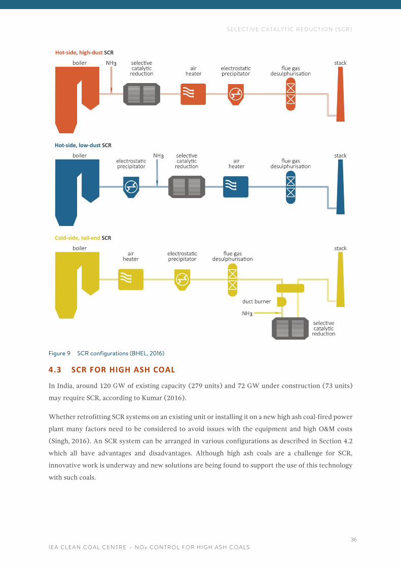
There are three typical SCR system layouts which can be applied to coal-fired power stations: high-dust,
low-dust and tail-end position (see Figure 9) (US EPA, 2016; BHEL, 2016; Miller, 2005; IEA CCC, nd).
The first one, also referred to as hot-side, high-dust, is the most widely used SCR configuration in
coal-fired power plants. In such an arrangement, an SCR is installed upstream of the PM control,
S E L E C T I V E C A T A L Y T I C R E D U C T I O N ( S C R )
I E A C L E A N C O A L C E N T R E – N O x C O N T R O L F O R H I G H A S H C O A L S
35
between the economiser and the air heater, where the temperature of the flue gas at this point is ideal
for the SCR reaction. Hence its popularity. However, in this configuration, the catalyst is exposed to
the fly ash and chemical components of the flue gas such as sulphur trioxide, which have the potential
to degrade it by ash erosion, particulate plugging and chemical reactions such as poisoning. These
issues can be addressed by proper design (US EPA, 2016; Miller, 2005). In the low-dust arrangement,
an SCR is installed downstream of the PM control equipment. Such a configuration, also referred to as
hot-side, low-dust, reduces degradation of the catalyst by fly ash erosion, but also needs a costly
hot-side ESP or a flue gas heating system to maintain the optimal temperature required for the catalytic
reaction of NOx (Reinhold, 2016; Miller, 2005; US EPA, 2016). In the tail-end configuration, also
referred to as cold-side, low-dust, the SCR is downstream of the flue gas desulphurisation (FGD) unit.
It may be used mainly in wet-bottom boilers and can be retrofitted on installations with space
constraints. A tail-end system may have higher capital and operating costs than the other SCR systems
because of the additional equipment and requirement of heating the flue gas and heat recovery.
However, this expense can be offset in part by reduction in the cost of the catalyst. This is because in
this configuration there is less fly ash, less catalyst poisons and SO2 in the flue gas, so the catalyst life
is significantly prolonged, which means that smaller amounts of a cheaper catalyst can be used
(US EPA, 2016).
S E L E C T I V E C A T A L Y T I C R E D U C T I O N ( S C R )
I E A C L E A N C O A L C E N T R E – N O x C O N T R O L F O R H I G H A S H C O A L S
36
Figure 9 SCR configurations (BHEL, 2016)
4.3 SCR FOR HIGH ASH COAL
In India, around 120 GW of existing capacity (279 units) and 72 GW under construction (73 units)
may require SCR, according to Kumar (2016).
Whether retrofitting SCR systems on an existing unit or installing it on a new high ash coal-fired power
plant many factors need to be considered to avoid issues with the equipment and high O&M costs
(Singh, 2016). An SCR system can be arranged in various configurations as described in Section 4.2
which all have advantages and disadvantages. Although high ash coals are a challenge for SCR,
innovative work is underway and new solutions are being found to support the use of this technology
with such coals.
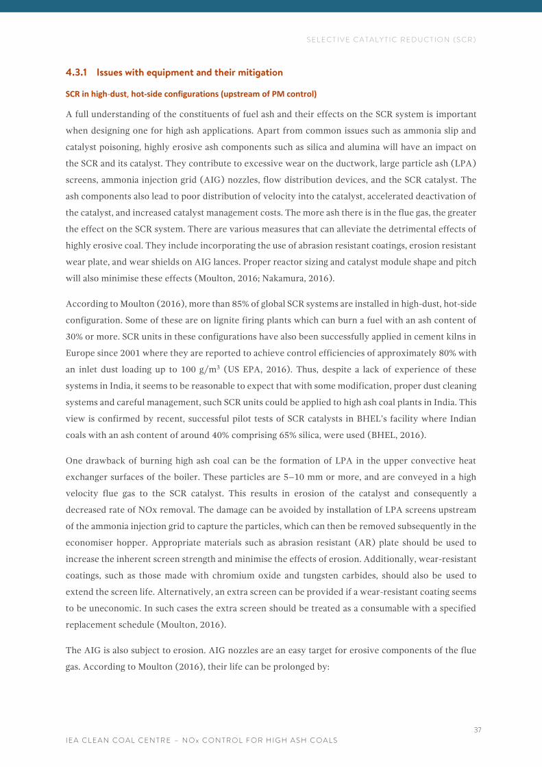
S E L E C T I V E C A T A L Y T I C R E D U C T I O N ( S C R )
I E A C L E A N C O A L C E N T R E – N O x C O N T R O L F O R H I G H A S H C O A L S
37
4.3.1 Issues with equipment and their mitigation
SCR in high-dust, hot-side configurations (upstream of PM control)
A full understanding of the constituents of fuel ash and their effects on the SCR system is important
when designing one for high ash applications. Apart from common issues such as ammonia slip and
catalyst poisoning, highly erosive ash components such as silica and alumina will have an impact on
the SCR and its catalyst. They contribute to excessive wear on the ductwork, large particle ash (LPA)
screens, ammonia injection grid (AIG) nozzles, flow distribution devices, and the SCR catalyst. The
ash components also lead to poor distribution of velocity into the catalyst, accelerated deactivation of
the catalyst, and increased catalyst management costs. The more ash there is in the flue gas, the greater
the effect on the SCR system. There are various measures that can alleviate the detrimental effects of
highly erosive coal. They include incorporating the use of abrasion resistant coatings, erosion resistant
wear plate, and wear shields on AIG lances. Proper reactor sizing and catalyst module shape and pitch
will also minimise these effects (Moulton, 2016; Nakamura, 2016).
According to Moulton (2016), more than 85% of global SCR systems are installed in high-dust, hot-side
configuration. Some of these are on lignite firing plants which can burn a fuel with an ash content of
30% or more. SCR units in these configurations have also been successfully applied in cement kilns in
Europe since 2001 where they are reported to achieve control efficiencies of approximately 80% with
an inlet dust loading up to 100 g/m3 (US EPA, 2016). Thus, despite a lack of experience of these
systems in India, it seems to be reasonable to expect that with some modification, proper dust cleaning
systems and careful management, such SCR units could be applied to high ash coal plants in India. This
view is confirmed by recent, successful pilot tests of SCR catalysts in BHEL’s facility where Indian
coals with an ash content of around 40% comprising 65% silica, were used (BHEL, 2016).
One drawback of burning high ash coal can be the formation of LPA in the upper convective heat
exchanger surfaces of the boiler. These particles are 5–10 mm or more, and are conveyed in a high
velocity flue gas to the SCR catalyst. This results in erosion of the catalyst and consequently a
decreased rate of NOx removal. The damage can be avoided by installation of LPA screens upstream
of the ammonia injection grid to capture the particles, which can then be removed subsequently in the
economiser hopper. Appropriate materials such as abrasion resistant (AR) plate should be used to
increase the inherent screen strength and minimise the effects of erosion. Additionally, wear-resistant
coatings, such as those made with chromium oxide and tungsten carbides, should also be used to
extend the screen life. Alternatively, an extra screen can be provided if a wear-resistant coating seems
to be uneconomic. In such cases the extra screen should be treated as a consumable with a specified
replacement schedule (Moulton, 2016).
The AIG is also subject to erosion. AIG nozzles are an easy target for erosive components of the flue
gas. According to Moulton (2016), their life can be prolonged by:
S E L E C T I V E C A T A L Y T I C R E D U C T I O N ( S C R )
I E A C L E A N C O A L C E N T R E – N O x C O N T R O L F O R H I G H A S H C O A L S
38
• designing the lances with an additional 1/8 inch (0.32 cm) of materials to account for anticipated
wear;
• using a more wear-resistant material such as 304 stainless steel; and
• installing sections of pipe, about one foot (0.3 m) deep into the duct, around each AIG header
pipe as such shields can neutralise the effects of high localised velocities near the duct wall
where the AIG enters into the flue gas.
Flow distribution devices such as turning vanes, static mixing elements, and distribution plates are also
subject to erosion. The role of the plates is to ensure optimal ammonia distribution and uniform flue
gas velocity before it enters the catalyst bed. Hence, they need to be of a durable design which includes
using erosion-resistant protective coatings and/or additional thickness of 1/16 inch (0.16 mm)
(Moulton, 2016).
The size of the SCR unit for each application needs to be decided carefully and the erosive nature of
the flue gas components must be considered. This is always achieved with help from CFD modelling.
In contrast to low-dust applications, the reactor should be designed with a larger cross-sectional area
so the catalyst faces velocities on the lower end of the design range at 2.4–3.0 m/s. This should ensure
sufficient contact between the flue gas and the catalyst for effective NOx reduction reaction. For a
low-dust environment the typical velocity through the catalyst is in the range of 3.7–5.5 m/s.
CFD modelling is also used to determine the distribution of velocity to minimise pressure drop and
particulate drop out. Identifying localised high velocities allows prediction of high wear sites within
the SCR unit and the ductwork. Based on this, it is possible to add additional erosion protection to the
most impacted locations. Furthermore, CFD modelling also can help assess potential operational issues,
including those that may occur due to the physical gaps between the catalyst modules. High velocity
zones can occur in such gaps and lead to accelerated deactivation of the catalyst and increased
maintenance costs (Moulton, 2016). However, some companies have already developed technologies
to mitigate these issues. For example, MHPS have patented a technology to minimise the gas angle and
velocity maldistribution by use of a guide vane and rectifier. This technology is believed to be
appropriate for high ash coal applications, including the Indian market (MHPS, 2016).
SCR in low-dust configuration
Placing the SCR in a low-dust position, downstream of PM control, will result in essentially a
particle-free flue gas stream. This will eliminate the requirement for LPA screens, extend the catalyst
life and reduce the maintenance costs associated with abrasion and erosion. On the other hand, it will
require heating of the flue gas to keep the catalyst at the right temperature for the complete NOx
reduction reaction, and to avoid formation of ammonia.
S E L E C T I V E C A T A L Y T I C R E D U C T I O N ( S C R )
I E A C L E A N C O A L C E N T R E – N O x C O N T R O L F O R H I G H A S H C O A L S
39
SCR in tail-end configuration
Another option for high ash coals would be to place an SCR system in the tail-end position (Nakamura,
2016). As noted by the US EPA (2016), tail-end systems have been used since the late 1980s and
applied in retrofits of many coal-fired power plants in Europe, as they are often easier and less complex
to install as a retrofit than other SCR type configurations. Thus, their application causes less disruption
to the power plant operation. Also, in some conditions, especially where there are space constraints,
the capital cost for retrofitting tail-end SCR can be lower than for high-dust SCR. Furthermore, tail-end
systems are available in modular forms which are designed to be installed with minimal disruption of
plant operation. However as described in Section 4.2, flue gas reheat is needed in this configuration.
According to Nakamura (2016), from JGC C&C, one good solution for Indian coals would be to place
an SCR after a dry FGD which uses a SOx adsorbent made of fly ash, calcium hydroxide and the used
SOx adsorbent as adhesive; as such the FGD can remove more than 85% of the dust. This, in
combination with an ESP, would mean a low-dust environment for an SCR and would avoid problems
related to a high ash environment, particularly erosion, plugging and clogging of catalyst.
4.4 SCR CATALYSTS
Different catalysts can be used in SCR systems. The catalysts are composed of active metals and/or
ceramics with a highly porous structure within which are active sites. These sites have an acid group
on the end of the compound structure where the NOx reduction reaction occurs. The sites are then
reactivated by rehydration or oxidation. There is a choice of catalyst available, and their final
composition can consist of many active metals and support materials to meet the specific requirements
of each SCR installation. However, most catalysts used in coal-fired plants consist of vanadium (usually
as V2O5 and often blended with tungsten oxide, WO3) as the active catalyst and titanium, usually as
TiO2, which is used to disperse and support the vanadium mixture. Catalyst geometry may also vary
depending on flue gas conditions and composition. Typically, catalysts have honeycomb, plate or
corrugated shapes (see Figure 10) (Sadler, 2013). Catalysts are packed at different depths in the
direction of the flue gas and arranged in many layers. Additionally, there are different pitches and/or
cell openings for different applications such as low-dust flue gas compared to high-dust flue gas
(Innovative Combustion, 2015). Catalyst pitch, which is defined as the width of the catalyst cell plus
the cell wall diameter, is an important parameter for catalyst design (US EPA, 2016). This is because
its size determines flue gas velocities inside the catalyst cells; for a given velocity, the wider the pitch
the lower the velocity. Consequently, an appropriate catalyst pitch is crucial to ensure that ash will not
deposit on catalyst cells and pores. For high-dust applications, such as cement kilns and coal-fired
boilers firing high ash coals, catalysts with larger openings or pitch can be used to reduce potential
plugging. However, the wider pitch reduces the surface area per unit volume which may require
additional catalyst volume and/or layers to meet the required rate of NOx removal and ammonia slip
(US EPA, 2016). Several manufacturers offer a variety of catalysts depending on the particulate matter
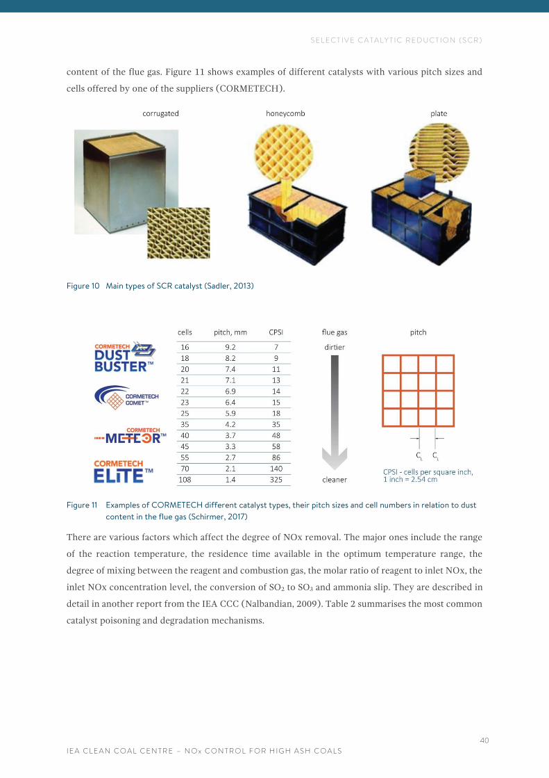
S E L E C T I V E C A T A L Y T I C R E D U C T I O N ( S C R )
I E A C L E A N C O A L C E N T R E – N O x C O N T R O L F O R H I G H A S H C O A L S
40
content of the flue gas. Figure 11 shows examples of different catalysts with various pitch sizes and
cells offered by one of the suppliers (CORMETECH).
Figure 10 Main types of SCR catalyst (Sadler, 2013)
Figure 11 Examples of CORMETECH different catalyst types, their pitch sizes and cell numbers in relation to dust
content in the flue gas (Schirmer, 2017)
There are various factors which affect the degree of NOx removal. The major ones include the range
of the reaction temperature, the residence time available in the optimum temperature range, the
degree of mixing between the reagent and combustion gas, the molar ratio of reagent to inlet NOx, the
inlet NOx concentration level, the conversion of SO2 to SO3 and ammonia slip. They are described in
detail in another report from the IEA CCC (Nalbandian, 2009). Table 2 summarises the most common
catalyst poisoning and degradation mechanisms.
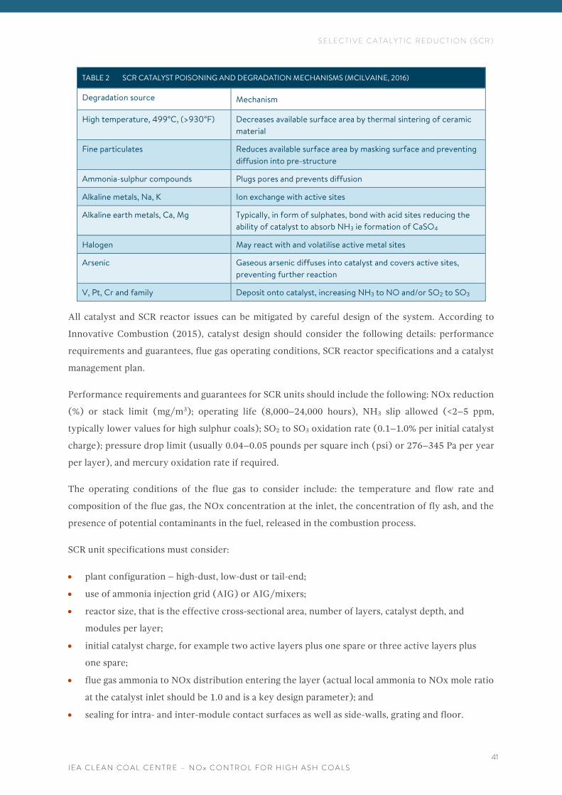
S E L E C T I V E C A T A L Y T I C R E D U C T I O N ( S C R )
I E A C L E A N C O A L C E N T R E – N O x C O N T R O L F O R H I G H A S H C O A L S
41
TABLE 2 SCR CATALYST POISONING AND DEGRADATION MECHANISMS (MCILVAINE, 2016)
Degradation source Mechanism
High temperature, 499°C, (>930°F) Decreases available surface area by thermal sintering of ceramic
material
Fine particulates Reduces available surface area by masking surface and preventing
diffusion into pre-structure
Ammonia-sulphur compounds Plugs pores and prevents diffusion
Alkaline metals, Na, K Ion exchange with active sites
Alkaline earth metals, Ca, Mg Typically, in form of sulphates, bond with acid sites reducing the
ability of catalyst to absorb NH3 ie formation of CaSO4
Halogen May react with and volatilise active metal sites
Arsenic Gaseous arsenic diffuses into catalyst and covers active sites,
preventing further reaction
V, Pt, Cr and family Deposit onto catalyst, increasing NH3 to NO and/or SO2 to SO3
All catalyst and SCR reactor issues can be mitigated by careful design of the system. According to
Innovative Combustion (2015), catalyst design should consider the following details: performance
requirements and guarantees, flue gas operating conditions, SCR reactor specifications and a catalyst
management plan.
Performance requirements and guarantees for SCR units should include the following: NOx reduction
(%) or stack limit (mg/m3); operating life (8,000–24,000 hours), NH3 slip allowed (<2–5 ppm,
typically lower values for high sulphur coals); SO2 to SO3 oxidation rate (0.1–1.0% per initial catalyst
charge); pressure drop limit (usually 0.04–0.05 pounds per square inch (psi) or 276–345 Pa per year
per layer), and mercury oxidation rate if required.
The operating conditions of the flue gas to consider include: the temperature and flow rate and
composition of the flue gas, the NOx concentration at the inlet, the concentration of fly ash, and the
presence of potential contaminants in the fuel, released in the combustion process.
SCR unit specifications must consider:
• plant configuration – high-dust, low-dust or tail-end;
• use of ammonia injection grid (AIG) or AIG/mixers;
• reactor size, that is the effective cross-sectional area, number of layers, catalyst depth, and
modules per layer;
• initial catalyst charge, for example two active layers plus one spare or three active layers plus
one spare;
• flue gas ammonia to NOx distribution entering the layer (actual local ammonia to NOx mole ratio
at the catalyst inlet should be 1.0 and is a key design parameter); and
• sealing for intra- and inter-module contact surfaces as well as side-walls, grating and floor.
S E L E C T I V E C A T A L Y T I C R E D U C T I O N ( S C R )
I E A C L E A N C O A L C E N T R E – N O x C O N T R O L F O R H I G H A S H C O A L S
42
Although the SCR catalyst manufacturers aim to provide an installed catalyst that operates at design
performance beyond its guaranteed life, both the manufacturer and the user should have a plan for if
there is a need to replace a layer of catalyst. The users should have a comprehensive catalyst
management plan (CCMP). This is in addition to the catalyst replacement plan from the manufacturer,
which is referred to as a catalyst management plan (CMP).
A CCMP has many important components:
• active analysis of SCR performance trends and evaluation of key indicators;
• periodic full load performance tests for NOx removal and ammonia slip under designed SCR
conditions;
• SCR reactor outage inspections with documentation of the system, which should include: reactor
flow devices, AIG and catalyst mapping (in terms of appearance and dust deposition on all
elements including seals, bypasses, modules and side-walls);
• following of SCR shut-down procedures and SCR catalyst outage protection;
• periodic sample extraction and analysis, either by a built-in sample log or coring of sample; and
• reviewing the supplier’s CMP with the first three items.
SCR performance trending and evaluation of parameters, such as rate of NOx removal, ammonia
consumption, ammonia slip (if equipped), and pressure differential, should not show any sudden
changes in performance at the same load for most systems. Deactivation should be gradual. If sudden
changes occur, such as a low rate of NOx removal, or ammonia being present in ash, or an increase in
the pressure drop, they should be investigated immediately.
If the rate of NOx reduction falls, then a physical analysis of the catalyst will include a determination
of its internal surface area. This will show whether the loss of activation is due to a decrease in the
active surface and/or if other mechanisms are preventing the reactants from reaching the active sites.
At the same time, chemical analyses of samples from the catalyst will identify the presence and extent
of catalyst poisons such as alkali metals, phosphorus, arsenic and chromium and blinding materials
such as calcium sulphate.
Once all checks have been performed, appropriate action can be taken. For example, a lower rate of
NOx reduction is often due to localised maldistribution of NOx and ammonia. This can be corrected
by AIG tuning (Innovative Combustion, 2015).
4.5 CATALYST ISSUES AND SOLUTIONS WITH HIGH ASH COALS
The performance of SCR catalysts with high ash coals, is mainly diminished by:
• ash clogging the catalyst cells;
• ash eroding the catalyst; and
• fouling by poisons such as calcium, and arsenic (Nakamura, 2016).
S E L E C T I V E C A T A L Y T I C R E D U C T I O N ( S C R )
I E A C L E A N C O A L C E N T R E – N O x C O N T R O L F O R H I G H A S H C O A L S
43
Catalyst issues described previously in Section 4.4 are also valid. Solutions include: careful selection
of the catalyst, a proper dust removal system, and reinforcement of the catalyst (Nakamura, 2016).
Proper selection of the catalyst
According to Schirmer (2017), there is a ‘common perception’ that the plate catalyst experiences less
plugging than the honeycomb type, but this is not the case. Both types of catalyst can be used in high
ash environments as long as they have the correct size of pitch. In general, a larger catalyst pitch is less
susceptible to plugging then a small one. However, as shown in tests and the commercial operation of
CORMETECH’s SCR catalyst, there is a cut-off in the optimum size of the pitch, as the inherent
performance of a very large pitch (>11 mm) is a compromise between no catalyst clogging and a higher
rate of replacement, higher local ammonia slip, and lower degree of NOx reduction.
Particle and dust removal systems
Fly ash and LPA must be properly managed so they do not accumulate. This is because ash plugging
increases the pressure drop across the SCR catalyst and diminishes its performance. Large ash particles
can be stopped by LPA screens and baffles and then removed in the hopper. Fly ash can be removed
by soot blowers and sonic horns and moved to the hopper (Nakamura, 2016).
Dust removal systems are generally installed between each catalyst layer and operate on a periodic
basis, such as once a week (US EPA, 2016). However, for high ash situations, frequent or continuous
cleaning of the catalyst may be required. As noted by Schirmer (2017), maintaining the frequency of
cleaning is critical to avoid accumulation of fly ash.
Reinforcement of the catalyst edge
Coating the catalyst edge with a reinforcing material will prevent erosion by the ash and will extend
the life of the catalyst (Nakamura, 2016).
Optimisation of pore structure of the catalyst
Optimisation of the catalyst pore structure is one of the key factors to prevent deactivation by plugging
and masking (Nakamura, 2016). This can be achieved by preparing a catalyst with a tri-modal pore
structure, which contains pores of three different sizes: micro, meso and macro (Jensen-Holm and
others, 2006; Haldor Topsoe, 2012). A tri-modal porous structure provides a high internal surface area
and more active sites. The micro-pores provide the required high specific surface area; the meso-pores
deliver resistance towards arsenic and other poisons such as CaO, as they can accommodate large
amounts of these substances; and the macro-pores help to enhance gas-phase diffusion of the reactants
(NOx and ammonia) into the catalyst, and thus assist overall catalyst activity (Jensen-Holm and others,
2006).
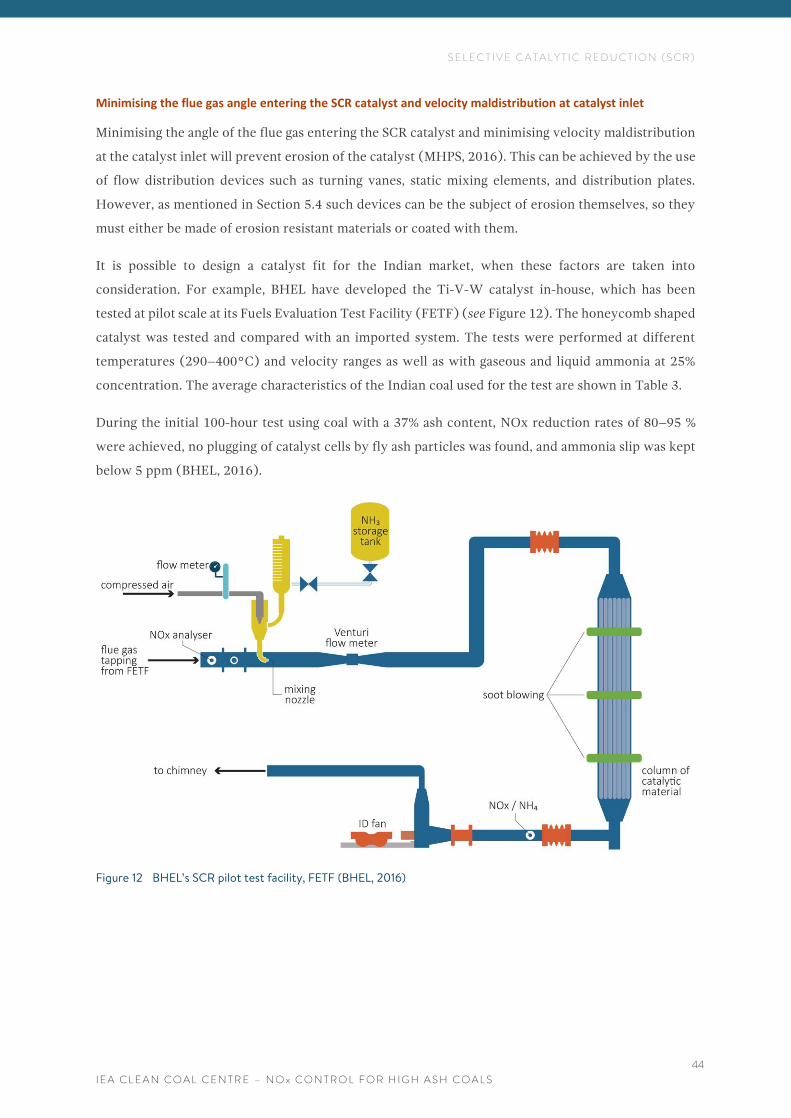
S E L E C T I V E C A T A L Y T I C R E D U C T I O N ( S C R )
I E A C L E A N C O A L C E N T R E – N O x C O N T R O L F O R H I G H A S H C O A L S
44
Minimising the flue gas angle entering the SCR catalyst and velocity maldistribution at catalyst inlet
Minimising the angle of the flue gas entering the SCR catalyst and minimising velocity maldistribution
at the catalyst inlet will prevent erosion of the catalyst (MHPS, 2016). This can be achieved by the use
of flow distribution devices such as turning vanes, static mixing elements, and distribution plates.
However, as mentioned in Section 5.4 such devices can be the subject of erosion themselves, so they
must either be made of erosion resistant materials or coated with them.
It is possible to design a catalyst fit for the Indian market, when these factors are taken into
consideration. For example, BHEL have developed the Ti-V-W catalyst in-house, which has been
tested at pilot scale at its Fuels Evaluation Test Facility (FETF) (see Figure 12). The honeycomb shaped
catalyst was tested and compared with an imported system. The tests were performed at different
temperatures (290–400°C) and velocity ranges as well as with gaseous and liquid ammonia at 25%
concentration. The average characteristics of the Indian coal used for the test are shown in Table 3.
During the initial 100-hour test using coal with a 37% ash content, NOx reduction rates of 80–95 %
were achieved, no plugging of catalyst cells by fly ash particles was found, and ammonia slip was kept
below 5 ppm (BHEL, 2016).
Figure 12 BHEL’s SCR pilot test facility, FETF (BHEL, 2016)
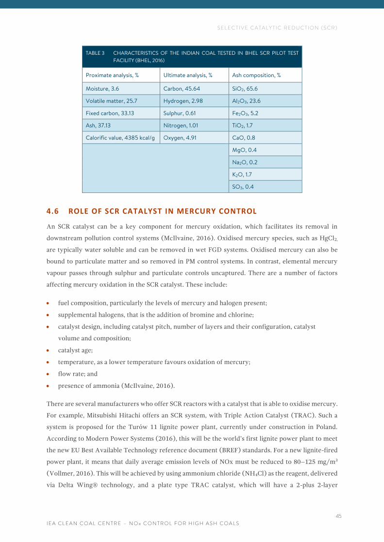
S E L E C T I V E C A T A L Y T I C R E D U C T I O N ( S C R )
I E A C L E A N C O A L C E N T R E – N O x C O N T R O L F O R H I G H A S H C O A L S
45
TABLE 3 CHARACTERISTICS OF THE INDIAN COAL TESTED IN BHEL SCR PILOT TEST
FACILITY (BHEL, 2016)
Proximate analysis, % Ultimate analysis, % Ash composition, %
Moisture, 3.6 Carbon, 45.64 SiO2, 65.6
Volatile matter, 25.7 Hydrogen, 2.98 Al2O3, 23.6
Fixed carbon, 33.13 Sulphur, 0.61 Fe2O3, 5.2
Ash, 37.13 Nitrogen, 1.01 TiO2, 1.7
Calorific value, 4385 kcal/g Oxygen, 4.91 CaO, 0.8
MgO, 0.4
Na2O, 0.2
K2O, 1.7
SO3, 0.4
4.6 ROLE OF SCR CATALYST IN MERCURY CONTROL
An SCR catalyst can be a key component for mercury oxidation, which facilitates its removal in
downstream pollution control systems (McIlvaine, 2016). Oxidised mercury species, such as HgCl2,
are typically water soluble and can be removed in wet FGD systems. Oxidised mercury can also be
bound to particulate matter and so removed in PM control systems. In contrast, elemental mercury
vapour passes through sulphur and particulate controls uncaptured. There are a number of factors
affecting mercury oxidation in the SCR catalyst. These include:
• fuel composition, particularly the levels of mercury and halogen present;
• supplemental halogens, that is the addition of bromine and chlorine;
• catalyst design, including catalyst pitch, number of layers and their configuration, catalyst
volume and composition;
• catalyst age;
• temperature, as a lower temperature favours oxidation of mercury;
• flow rate; and
• presence of ammonia (McIlvaine, 2016).
There are several manufacturers who offer SCR reactors with a catalyst that is able to oxidise mercury.
For example, Mitsubishi Hitachi offers an SCR system, with Triple Action Catalyst (TRAC). Such a
system is proposed for the Turów 11 lignite power plant, currently under construction in Poland.
According to Modern Power Systems (2016), this will be the world’s first lignite power plant to meet
the new EU Best Available Technology reference document (BREF) standards. For a new lignite-fired
power plant, it means that daily average emission levels of NOx must be reduced to 80–125 mg/m3
(Vollmer, 2016). This will be achieved by using ammonium chloride (NH4Cl) as the reagent, delivered
via Delta Wing® technology, and a plate type TRAC catalyst, which will have a 2-plus 2-layer
S E L E C T I V E C A T A L Y T I C R E D U C T I O N ( S C R )
I E A C L E A N C O A L C E N T R E – N O x C O N T R O L F O R H I G H A S H C O A L S
46
arrangement. This will result in a NOx level at the SCR outlet of 85 mg/m3, a high rate of mercury
oxidation and low conversion of SO2 to SO3 (Vollmer, 2016). Mitsubishi’s SCR has already been
installed on various lignite plants in Austria, China, Germany, Thailand and the USA, so it is reasonable
to expect that the Turów 11 power plant will achieve the NOx level predicted. Turów 11 will burn a
locally mined lignite with an ash content of around 30%. Other catalyst suppliers who offer products
that enhance mercury oxidation include: Johnson Matthey, CORMETECH and Haldor Topsoe.
4.7 COMMENTS
SCR is the most effective method to control NOx as it can achieve 80–90% NOx reduction. However,
it is also the most expensive. The current practice in coal-fired power plants is to deploy many NOx
control options simultaneously, which leads to significant emissions reduction.
SCR systems can be applied in different layouts at coal-fired power stations as well as in combination
with an SNCR. In the hot-side, high-dust arrangement, an SCR is located upstream of PM control,
between the economiser and the air heater, where the flue gas temperature is ideal for SCR reactions.
Hence this configuration is the most widely used in coal-fired power plants (Henderson, 2017). In the
second one, an SCR is installed after PM control, whereas in the third one an SCR is installed
downstream of the FGD unit. Depending on the layout, the SCR catalyst is exposed to different flue
gas components and properties which can influence its effectiveness and lifetime. Additionally, in the
first two arrangements, an SCR catalyst can be a key component for mercury oxidation which
facilitates its removal in downstream pollution control systems.
As SCR design is highly site-specific, SCR systems differ between power plants, and the capital and
operating costs vary.
There is a lack of SCR commercial installations in India, but the experience from high ash lignite-fired
plants as well as from high-dust industries such as cement kilns, plus initial results from BHEL’s tests
in India, all seem to confirm the potential of this technology for NOx reduction in high ash coal
applications. For example, in China, there has been a positive experience of SCR operation in coal fired
plants, with ash loading in the flue gas as high as 70 g/m3 (MHPS, 2017). Although the SCR units can
be applied both to new and existing power plants it is unlikely that they will be installed on older units,
in operation before 2003 as their NOx emission limits of 600 mg/m3 can be met by cheaper control
methods. SCR may also be a control option for existing plants, which came online between January
2003 and December 2016, as they are required to limit their emissions below 300 mg/m3. However,
these emission levels can be achieved by a combination of less expensive solutions, such as primary
measures and SNCR, or primary measures and multi-pollutant controls. In contrast to the older plants,
new units which come online after January 2017, are required to achieve NOx emissions below
100 mg/m3. The only option for new units. may be to install an SCR in combination with primary
measures such as LNBs or OFA and perhaps with SNCR added.

S E L E C T I V E C A T A L Y T I C R E D U C T I O N ( S C R )
I E A C L E A N C O A L C E N T R E – N O x C O N T R O L F O R H I G H A S H C O A L S
47
Currently, eight units of the NTPC have undertaken pilot projects to establish the efficacy of globally
available SCR and SNCR technology to reduce NOx emissions from burning Indian coal. The results
will be known in 2018-19 and then the Ministry of Environment Forest and Climate Change (MoEFCC)
will be requested to review the norms of 300 mg/m3 and 100 mg/m3. Consequently, no utilities are
expected to make any decision regarding the purchase of such systems before 2019 (SRPC, 2017;
NTPC, 2017).
S E L E C T I V E N O N - C A T A L Y T I C R E D U C T I O N ( S N C R )
I E A C L E A N C O A L C E N T R E – N O x C O N T R O L F O R H I G H A S H C O A L S
48
5 S E L E C T I V E N O N - C A T A L Y T I C R E D U C T I O N
( S N C R )
SNCR is a process which reduces NOx by injecting a reagent, either ammonia or urea, into the boiler’s
furnace at locations which have an appropriate temperature window, typically between 900–1100°C
depending on the reagent and conditions of SNCR operation. In contrast to selective catalytic
reduction, SNCR systems do not use a catalyst. The NOx and reagent react to form nitrogen and water
and typically have a chemical utilisation rate of around 30%, on a molar basis, although this is highly
dependent on the furnace conditions (Boyle and Rankin, 2016).
The main reactions are:
Using urea
4NO + 2CO(NH2)2 + O2 = 4N2 + 2CO2 + 4H2O
2NO2 + 2CO(NH2)2 + O2 = 3N2 + 2CO2 + 4H2O
Using ammonia
NO + 4NH3 + O2 + 4N2 + 6H2O
The effectiveness of the system depends on sufficient residence time within the flue gas temperature
window and adequate mixing of the reagent with the flue gas. The CO and O2 levels also have an effect.
Hence the system must be designed with care. For example, if the reagent is injected in the part of the
furnace where the temperature is too high, the ammonia, or urea decomposed to ammonia, will
produce additional NO. Alternatively, if the temperature is too low, the NOx reduction reaction will
not occur, and the ammonia will remain as ammonia slip and be wasted. Additionally, ammonia slip
can react with SO2 present in the flue gas to form ammonium sulphate and ammonium bisulphate.
Ammonium bisulphate tends to condense on the cooler surfaces of the air heater and can cause
significant loss of efficiency, in addition to mechanical damage (Xu and others, 2015). As shown in
Figure 13, CO levels within the furnace can have a significant effect on NOx reduction. When the CO
level of the point of chemical injection increases, the ideal temperature changes from 1005°C to 925°C
and 860°C. Ammonia slip also starts to increase significantly with lower temperatures (de Havilland,
2016).
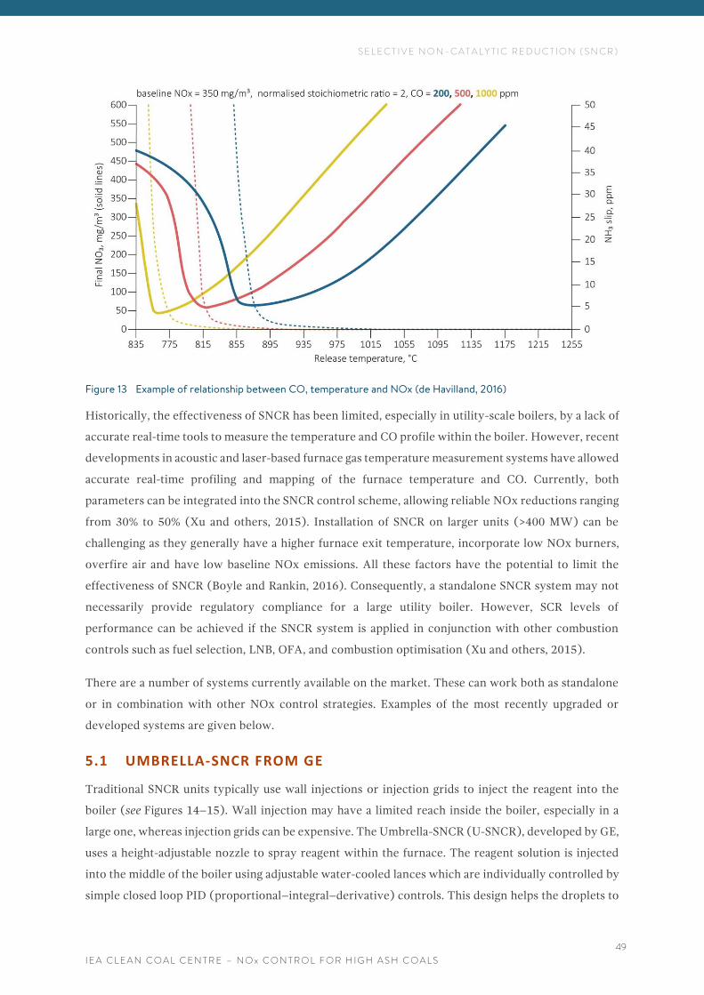
S E L E C T I V E N O N - C A T A L Y T I C R E D U C T I O N ( S N C R )
I E A C L E A N C O A L C E N T R E – N O x C O N T R O L F O R H I G H A S H C O A L S
49
Figure 13 Example of relationship between CO, temperature and NOx (de Havilland, 2016)
Historically, the effectiveness of SNCR has been limited, especially in utility-scale boilers, by a lack of
accurate real-time tools to measure the temperature and CO profile within the boiler. However, recent
developments in acoustic and laser-based furnace gas temperature measurement systems have allowed
accurate real-time profiling and mapping of the furnace temperature and CO. Currently, both
parameters can be integrated into the SNCR control scheme, allowing reliable NOx reductions ranging
from 30% to 50% (Xu and others, 2015). Installation of SNCR on larger units (>400 MW) can be
challenging as they generally have a higher furnace exit temperature, incorporate low NOx burners,
overfire air and have low baseline NOx emissions. All these factors have the potential to limit the
effectiveness of SNCR (Boyle and Rankin, 2016). Consequently, a standalone SNCR system may not
necessarily provide regulatory compliance for a large utility boiler. However, SCR levels of
performance can be achieved if the SNCR system is applied in conjunction with other combustion
controls such as fuel selection, LNB, OFA, and combustion optimisation (Xu and others, 2015).
There are a number of systems currently available on the market. These can work both as standalone
or in combination with other NOx control strategies. Examples of the most recently upgraded or
developed systems are given below.
5.1 UMBRELLA-SNCR FROM GE
Traditional SNCR units typically use wall injections or injection grids to inject the reagent into the
boiler (see Figures 14–15). Wall injection may have a limited reach inside the boiler, especially in a
large one, whereas injection grids can be expensive. The Umbrella-SNCR (U-SNCR), developed by GE,
uses a height-adjustable nozzle to spray reagent within the furnace. The reagent solution is injected
into the middle of the boiler using adjustable water-cooled lances which are individually controlled by
simple closed loop PID (proportional–integral–derivative) controls. This design helps the droplets to
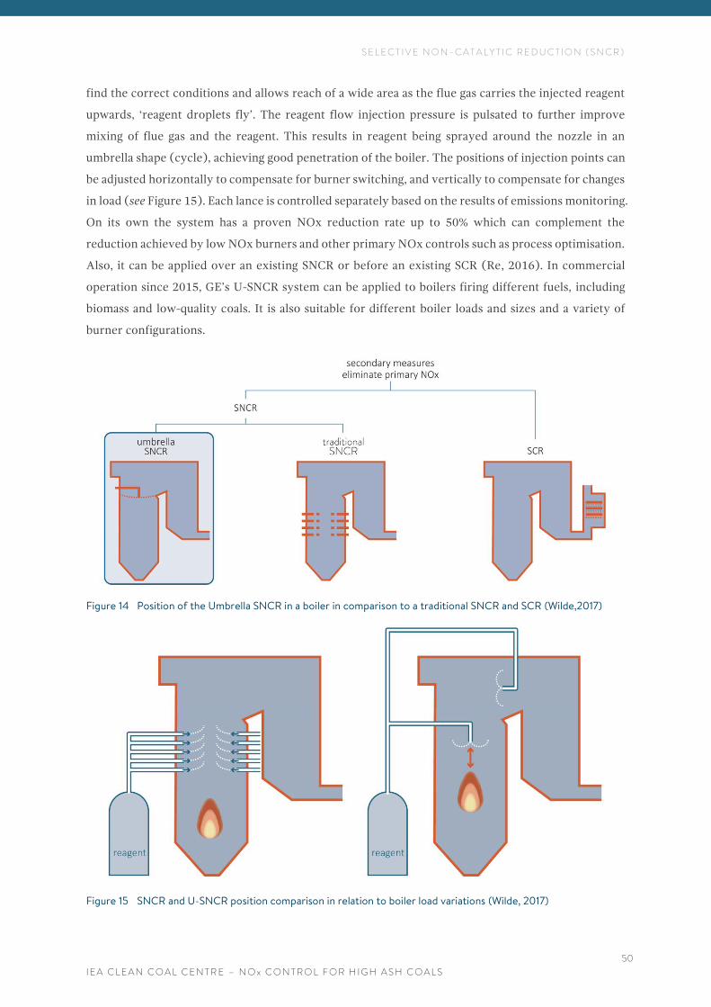
S E L E C T I V E N O N - C A T A L Y T I C R E D U C T I O N ( S N C R )
I E A C L E A N C O A L C E N T R E – N O x C O N T R O L F O R H I G H A S H C O A L S
50
find the correct conditions and allows reach of a wide area as the flue gas carries the injected reagent
upwards, ‘reagent droplets fly’. The reagent flow injection pressure is pulsated to further improve
mixing of flue gas and the reagent. This results in reagent being sprayed around the nozzle in an
umbrella shape (cycle), achieving good penetration of the boiler. The positions of injection points can
be adjusted horizontally to compensate for burner switching, and vertically to compensate for changes
in load (see Figure 15). Each lance is controlled separately based on the results of emissions monitoring.
On its own the system has a proven NOx reduction rate up to 50% which can complement the
reduction achieved by low NOx burners and other primary NOx controls such as process optimisation.
Also, it can be applied over an existing SNCR or before an existing SCR (Re, 2016). In commercial
operation since 2015, GE’s U-SNCR system can be applied to boilers firing different fuels, including
biomass and low-quality coals. It is also suitable for different boiler loads and sizes and a variety of
burner configurations.
Figure 14 Position of the Umbrella SNCR in a boiler in comparison to a traditional SNCR and SCR (Wilde,2017)
Figure 15 SNCR and U-SNCR position comparison in relation to boiler load variations (Wilde, 2017)
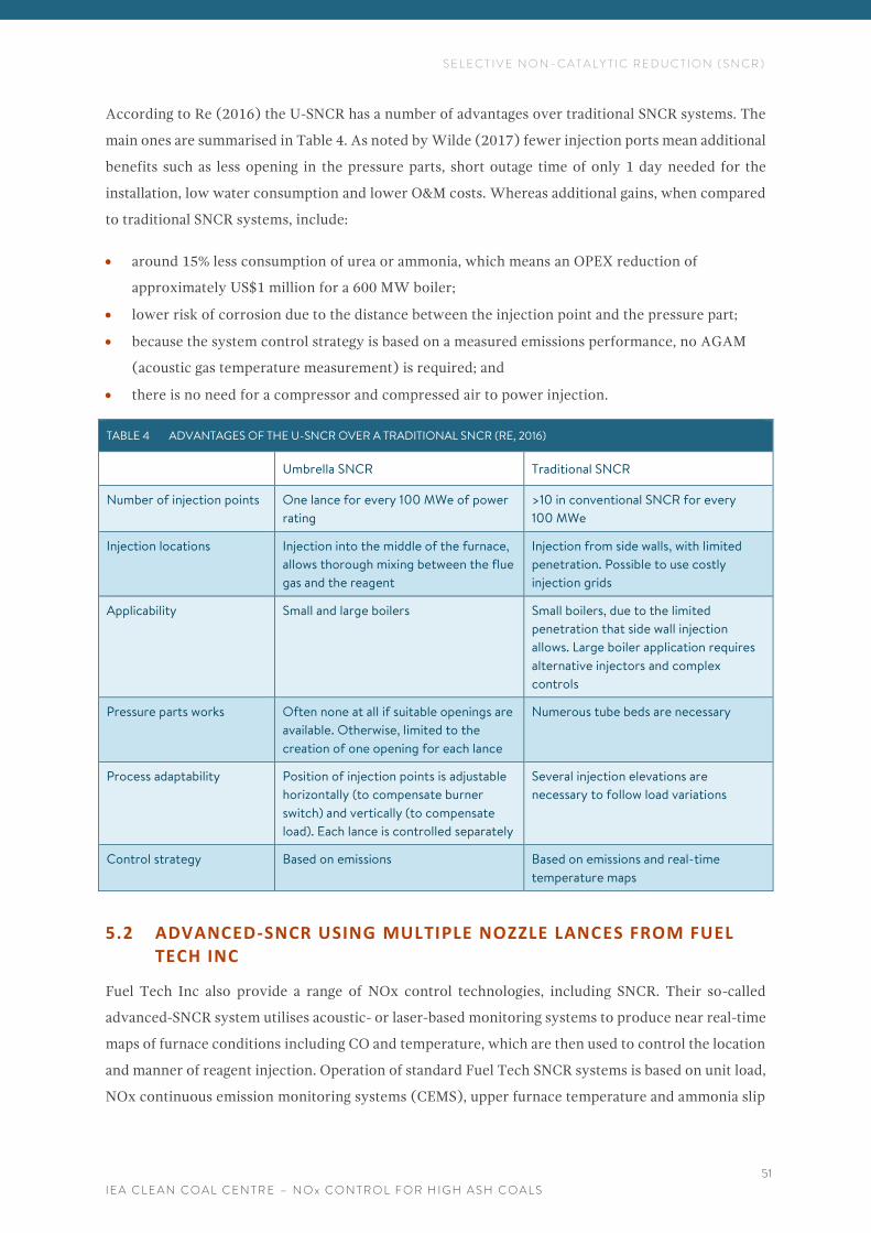
S E L E C T I V E N O N - C A T A L Y T I C R E D U C T I O N ( S N C R )
I E A C L E A N C O A L C E N T R E – N O x C O N T R O L F O R H I G H A S H C O A L S
51
According to Re (2016) the U-SNCR has a number of advantages over traditional SNCR systems. The
main ones are summarised in Table 4. As noted by Wilde (2017) fewer injection ports mean additional
benefits such as less opening in the pressure parts, short outage time of only 1 day needed for the
installation, low water consumption and lower O&M costs. Whereas additional gains, when compared
to traditional SNCR systems, include:
• around 15% less consumption of urea or ammonia, which means an OPEX reduction of
approximately US$1 million for a 600 MW boiler;
• lower risk of corrosion due to the distance between the injection point and the pressure part;
• because the system control strategy is based on a measured emissions performance, no AGAM
(acoustic gas temperature measurement) is required; and
• there is no need for a compressor and compressed air to power injection.
TABLE 4 ADVANTAGES OF THE U-SNCR OVER A TRADITIONAL SNCR (RE, 2016)
Umbrella SNCR Traditional SNCR
Number of injection points One lance for every 100 MWe of power
rating
>10 in conventional SNCR for every
100 MWe
Injection locations Injection into the middle of the furnace,
allows thorough mixing between the flue
gas and the reagent
Injection from side walls, with limited
penetration. Possible to use costly
injection grids
Applicability Small and large boilers Small boilers, due to the limited
penetration that side wall injection
allows. Large boiler application requires
alternative injectors and complex
controls
Pressure parts works Often none at all if suitable openings are
available. Otherwise, limited to the
creation of one opening for each lance
Numerous tube beds are necessary
Process adaptability Position of injection points is adjustable
horizontally (to compensate burner
switch) and vertically (to compensate
load). Each lance is controlled separately
Several injection elevations are
necessary to follow load variations
Control strategy Based on emissions Based on emissions and real-time
temperature maps
5.2 ADVANCED-SNCR USING MULTIPLE NOZZLE LANCES FROM FUEL TECH INC
Fuel Tech Inc also provide a range of NOx control technologies, including SNCR. Their so-called
advanced-SNCR system utilises acoustic- or laser-based monitoring systems to produce near real-time
maps of furnace conditions including CO and temperature, which are then used to control the location
and manner of reagent injection. Operation of standard Fuel Tech SNCR systems is based on unit load,
NOx continuous emission monitoring systems (CEMS), upper furnace temperature and ammonia slip
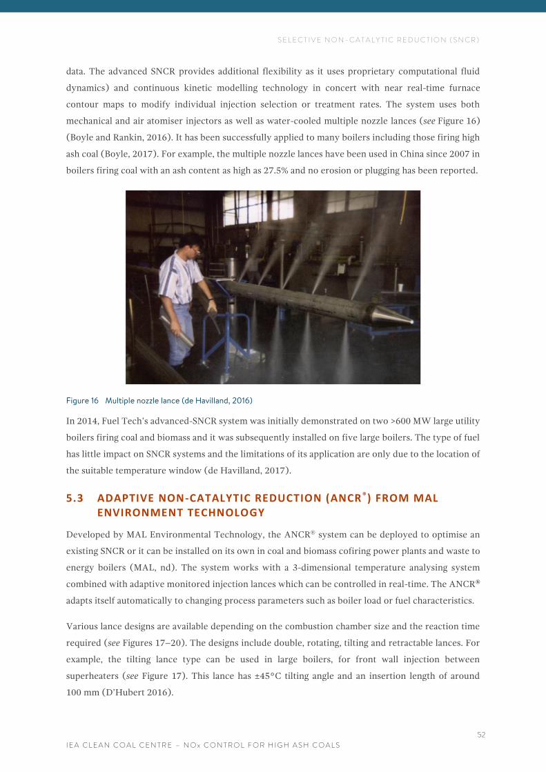
S E L E C T I V E N O N - C A T A L Y T I C R E D U C T I O N ( S N C R )
I E A C L E A N C O A L C E N T R E – N O x C O N T R O L F O R H I G H A S H C O A L S
52
data. The advanced SNCR provides additional flexibility as it uses proprietary computational fluid
dynamics) and continuous kinetic modelling technology in concert with near real-time furnace
contour maps to modify individual injection selection or treatment rates. The system uses both
mechanical and air atomiser injectors as well as water-cooled multiple nozzle lances (see Figure 16)
(Boyle and Rankin, 2016). It has been successfully applied to many boilers including those firing high
ash coal (Boyle, 2017). For example, the multiple nozzle lances have been used in China since 2007 in
boilers firing coal with an ash content as high as 27.5% and no erosion or plugging has been reported.
Figure 16 Multiple nozzle lance (de Havilland, 2016)
In 2014, Fuel Tech’s advanced-SNCR system was initially demonstrated on two >600 MW large utility
boilers firing coal and biomass and it was subsequently installed on five large boilers. The type of fuel
has little impact on SNCR systems and the limitations of its application are only due to the location of
the suitable temperature window (de Havilland, 2017).
5.3 ADAPTIVE NON-CATALYTIC REDUCTION (ANCR ®) FROM MAL ENVIRONMENT TECHNOLOGY
Developed by MAL Environmental Technology, the ANCR® system can be deployed to optimise an
existing SNCR or it can be installed on its own in coal and biomass cofiring power plants and waste to
energy boilers (MAL, nd). The system works with a 3-dimensional temperature analysing system
combined with adaptive monitored injection lances which can be controlled in real-time. The ANCR®
adapts itself automatically to changing process parameters such as boiler load or fuel characteristics.
Various lance designs are available depending on the combustion chamber size and the reaction time
required (see Figures 17–20). The designs include double, rotating, tilting and retractable lances. For
example, the tilting lance type can be used in large boilers, for front wall injection between
superheaters (see Figure 17). This lance has ±45°C tilting angle and an insertion length of around
100 mm (D’Hubert 2016).
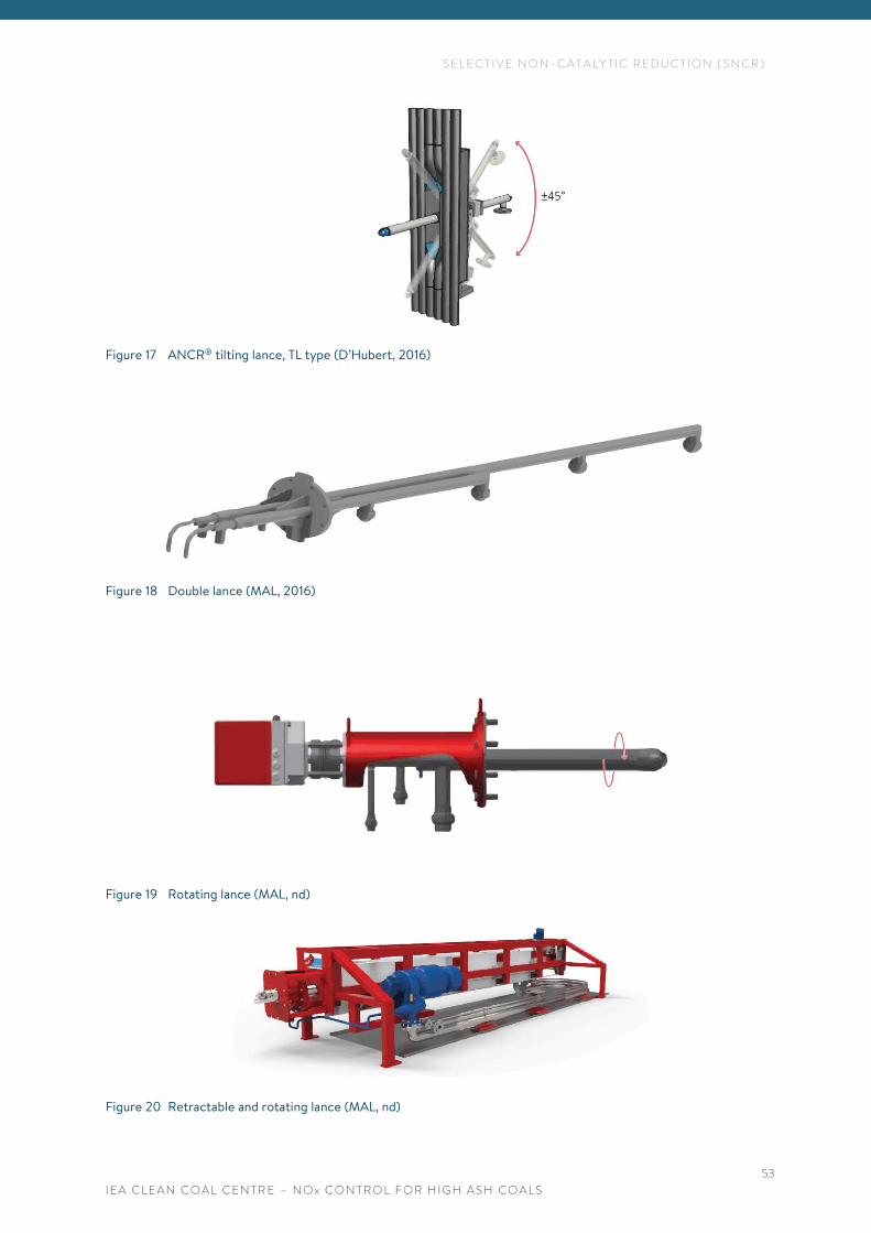
S E L E C T I V E N O N - C A T A L Y T I C R E D U C T I O N ( S N C R )
I E A C L E A N C O A L C E N T R E – N O x C O N T R O L F O R H I G H A S H C O A L S
53
Figure 17 ANCR® tilting lance, TL type (D’Hubert, 2016)
Figure 18 Double lance (MAL, 2016)
Figure 19 Rotating lance (MAL, nd)
Figure 20 Retractable and rotating lance (MAL, nd)
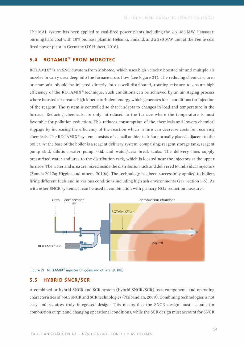
S E L E C T I V E N O N - C A T A L Y T I C R E D U C T I O N ( S N C R )
I E A C L E A N C O A L C E N T R E – N O x C O N T R O L F O R H I G H A S H C O A L S
54
The MAL system has been applied to coal-fired power plants including the 2 x 363 MW Hanasaari
burning hard coal with 10% biomass plant in Helsinki, Finland, and a 230 MW unit at the Fenne coal
fired power plant in Germany (D’ Hubert, 2016).
5.4 ROTAMIX® FROM MOBOTEC
ROTAMIX® is an SNCR system from Mobotec, which uses high velocity boosted air and multiple air
nozzles to carry urea deep into the furnace cross flow (see Figure 21). The reducing chemicals, urea
or ammonia, should be injected directly into a well-distributed, rotating mixture to ensure high
efficiency of the ROTAMIX® technique. Such conditions can be achieved by an air staging process
where boosted air creates high kinetic turbulent energy which generates ideal conditions for injection
of the reagent. The system is controlled so that it adapts to changes in load and temperature in the
furnace. Reducing chemicals are only introduced to the furnace where the temperature is most
favorable for pollution reduction. This reduces consumption of the chemicals and lowers chemical
slippage by increasing the efficiency of the reaction which in turn can decrease costs for recurring
chemicals. The ROTAMIX® system consists of a small ambient-air fan normally placed adjacent to the
boiler. At the base of the boiler is a reagent delivery system, comprising: reagent storage tank, reagent
pump skid, dilution water pump skid, and water/urea break tanks. The delivery lines supply
pressurised water and urea to the distribution rack, which is located near the injectors at the upper
furnace. The water and urea are mixed inside the distribution rack and delivered to individual injectors
(Żmuda 2017a; Higgins and others, 2010a). The technology has been successfully applied to boilers
firing different fuels and in various conditions including high ash environments (see Section 5.6). As
with other SNCR systems, it can be used in combination with primary NOx reduction measures.
Figure 21 ROTAMIX® injector (Higgins and others, 2010b)
5.5 HYBRID SNCR/SCR
A combined or hybrid SNCR and SCR system (hybrid SNCR/SCR) uses components and operating
characteristics of both SNCR and SCR technologies (Nalbandian, 2009). Combining technologies is not
easy and requires truly integrated design. This means that the SNCR design must account for
combustion output and changing operational conditions, while the SCR design must account for SNCR
S E L E C T I V E N O N - C A T A L Y T I C R E D U C T I O N ( S N C R )
I E A C L E A N C O A L C E N T R E – N O x C O N T R O L F O R H I G H A S H C O A L S
55
output and varying conditions of the combustion and SCR systems as boiler conditions fluctuate
(McIlvaine, 2016). As noted by de Havilland (2017), a combination system is more likely to be
installed onto an existing boiler where space constraints can make the construction cost of a full SCR
prohibitive. The hybrid system can also be installed in stages as regulations change allowing a site to
spread the capital outlay over several years. For a new site, designing SCR from the start may be the
most cost-effective solution over its lifetime (de Havilland, 2017).
5.5.1 I-NOx from Fuel Tech Inc
Fuel Tech’s I-NOx is an example of the SNCR/SCR system. According to de Havilland (2017), it takes
the hybrid SNCR/SCR system one step further and allows the combustion system to be tuned to
maximise the operation of the SNCR system, while the ratio of the NOx reduction achieved between
the SNCR system and the SCR system is optimised for when the catalyst is new. Greater NOx reduction
can be achieved with lower consumption of the reagent. However, the catalyst loses reactivity as it
nears the end of its life, so the SNCR system must then provide a greater reduction of NOx
(de Havilland, 2017).
5.6 SELECTIVE NON-CATALYTIC REDUCTION FOR HIGH ASH COALS
Although SNCR technology has not yet been used with Indian coals, it has been proven in high ash
coal applications. These include installations on coal-fired plants burning lignite and bituminous coal
with an ash content of around 30%, as well as on CFB boilers and cement kilns, where the fly ash
loading can be even higher at 90–100 g/m3, compared to Indian boilers (up to around 80 g/m3). In
cement kilns, SNCR has been reported to achieve a reduction in NOx of 12–77% for systems using
ammonia and of 25–90% for those using urea as the reagent (US EPA, 2015). However different NOx
reduction rates are reported for coal-fired plants: of up to 50% for an SNCR unit on its own, and of up
to 90% when an SNCR unit is combined with primary measures (Xu and others, 2015). SNCR
manufacturers with long experience of high ash coal environments include Fuel Tech Inc whose
systems have wall-injectors and multiple-nozzle lances and Mobotec who developed ROTAMIX®.
Based on this evidence, various experts and equipment manufacturers are confident that SNCR can be
successfully used in Indian coal-fired plants, especially for the units which must reduce their NOx
emissions below 300, or 100 mg/m3 (Boyle, 2017; de Havilland, 2017; Żmuda, 2017a).
SNCR applied in combination with primary NOx measures such as LNBs and OFA will meet the
300 mg/m3 limits and is an alternative to SCR. However, for new plants which have 100 mg/m3 NOx
emission limits, an SNCR in combination with a small SCR is an option. According to Boyle (2017),
such a combination applied to Indian boilers would bring the cost of an SCR catalyst down as fewer
layers would be required. Additionally, a smaller SCR unit with fewer layers of catalyst in the duct or
standalone has many benefits. First, at low load, the temperature of the flue gas at the SCR reactor may
be too low for effective operation. In this condition, an upstream SNCR system can still provide some
level of NOx control. Second, catalyst poisons may force replacement of catalyst modules which is
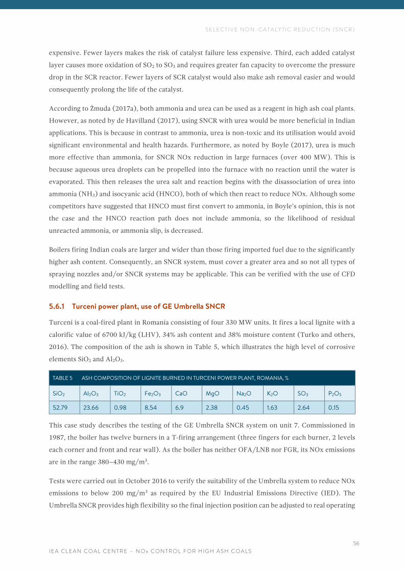
S E L E C T I V E N O N - C A T A L Y T I C R E D U C T I O N ( S N C R )
I E A C L E A N C O A L C E N T R E – N O x C O N T R O L F O R H I G H A S H C O A L S
56
expensive. Fewer layers makes the risk of catalyst failure less expensive. Third, each added catalyst
layer causes more oxidation of SO2 to SO3 and requires greater fan capacity to overcome the pressure
drop in the SCR reactor. Fewer layers of SCR catalyst would also make ash removal easier and would
consequently prolong the life of the catalyst.
According to Żmuda (2017a), both ammonia and urea can be used as a reagent in high ash coal plants.
However, as noted by de Havilland (2017), using SNCR with urea would be more beneficial in Indian
applications. This is because in contrast to ammonia, urea is non-toxic and its utilisation would avoid
significant environmental and health hazards. Furthermore, as noted by Boyle (2017), urea is much
more effective than ammonia, for SNCR NOx reduction in large furnaces (over 400 MW). This is
because aqueous urea droplets can be propelled into the furnace with no reaction until the water is
evaporated. This then releases the urea salt and reaction begins with the disassociation of urea into
ammonia (NH3) and isocyanic acid (HNCO), both of which then react to reduce NOx. Although some
competitors have suggested that HNCO must first convert to ammonia, in Boyle’s opinion, this is not
the case and the HNCO reaction path does not include ammonia, so the likelihood of residual
unreacted ammonia, or ammonia slip, is decreased.
Boilers firing Indian coals are larger and wider than those firing imported fuel due to the significantly
higher ash content. Consequently, an SNCR system, must cover a greater area and so not all types of
spraying nozzles and/or SNCR systems may be applicable. This can be verified with the use of CFD
modelling and field tests.
5.6.1 Turceni power plant, use of GE Umbrella SNCR
Turceni is a coal-fired plant in Romania consisting of four 330 MW units. It fires a local lignite with a
calorific value of 6700 kJ/kg (LHV), 34% ash content and 38% moisture content (Turko and others,
2016). The composition of the ash is shown in Table 5, which illustrates the high level of corrosive
elements SiO2 and Al2O3.
TABLE 5 ASH COMPOSITION OF LIGNITE BURNED IN TURCENI POWER PLANT, ROMANIA, %
SiO2 Al2O3 TiO2 Fe2O3 CaO MgO Na2O K2O SO3 P2O5
52.79 23.66 0.98 8.54 6.9 2.38 0.45 1.63 2.64 0.15
This case study describes the testing of the GE Umbrella SNCR system on unit 7. Commissioned in
1987, the boiler has twelve burners in a T-firing arrangement (three fingers for each burner, 2 levels
each corner and front and rear wall). As the boiler has neither OFA/LNB nor FGR, its NOx emissions
are in the range 380–430 mg/m3.
Tests were carried out in October 2016 to verify the suitability of the Umbrella system to reduce NOx
emissions to below 200 mg/m3 as required by the EU Industrial Emissions Directive (IED). The
Umbrella SNCR provides high flexibility so the final injection position can be adjusted to real operating
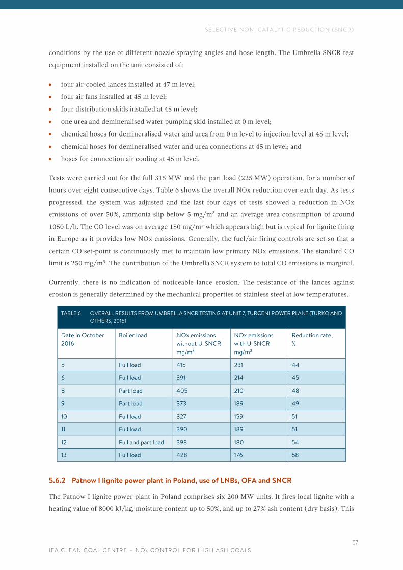
S E L E C T I V E N O N - C A T A L Y T I C R E D U C T I O N ( S N C R )
I E A C L E A N C O A L C E N T R E – N O x C O N T R O L F O R H I G H A S H C O A L S
57
conditions by the use of different nozzle spraying angles and hose length. The Umbrella SNCR test
equipment installed on the unit consisted of:
• four air-cooled lances installed at 47 m level;
• four air fans installed at 45 m level;
• four distribution skids installed at 45 m level;
• one urea and demineralised water pumping skid installed at 0 m level;
• chemical hoses for demineralised water and urea from 0 m level to injection level at 45 m level;
• chemical hoses for demineralised water and urea connections at 45 m level; and
• hoses for connection air cooling at 45 m level.
Tests were carried out for the full 315 MW and the part load (225 MW) operation, for a number of
hours over eight consecutive days. Table 6 shows the overall NOx reduction over each day. As tests
progressed, the system was adjusted and the last four days of tests showed a reduction in NOx
emissions of over 50%, ammonia slip below 5 mg/m3 and an average urea consumption of around
1050 L/h. The CO level was on average 150 mg/m3 which appears high but is typical for lignite firing
in Europe as it provides low NOx emissions. Generally, the fuel/air firing controls are set so that a
certain CO set-point is continuously met to maintain low primary NOx emissions. The standard CO
limit is 250 mg/m³. The contribution of the Umbrella SNCR system to total CO emissions is marginal.
Currently, there is no indication of noticeable lance erosion. The resistance of the lances against
erosion is generally determined by the mechanical properties of stainless steel at low temperatures.
TABLE 6 OVERALL RESULTS FROM UMBRELLA SNCR TESTING AT UNIT 7, TURCENI POWER PLANT (TURKO AND
OTHERS, 2016)
Date in October
2016
Boiler load NOx emissions
without U-SNCR
mg/m3
NOx emissions
with U-SNCR
mg/m3
Reduction rate,
%
5 Full load 415 231 44
6 Full load 391 214 45
8 Part load 405 210 48
9 Part load 373 189 49
10 Full load 327 159 51
11 Full load 390 189 51
12 Full and part load 398 180 54
13 Full load 428 176 58
5.6.2 Patnow I lignite power plant in Poland, use of LNBs, OFA and SNCR
The Patnow I lignite power plant in Poland comprises six 200 MW units. It fires local lignite with a
heating value of 8000 kJ/kg, moisture content up to 50%, and up to 27% ash content (dry basis). This
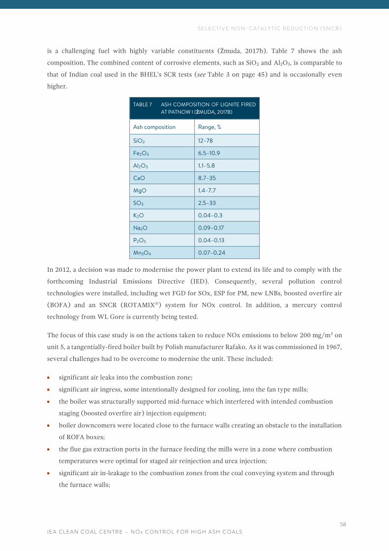
S E L E C T I V E N O N - C A T A L Y T I C R E D U C T I O N ( S N C R )
I E A C L E A N C O A L C E N T R E – N O x C O N T R O L F O R H I G H A S H C O A L S
58
is a challenging fuel with highly variable constituents (Żmuda, 2017b). Table 7 shows the ash
composition. The combined content of corrosive elements, such as SiO2 and Al2O3, is comparable to
that of Indian coal used in the BHEL’s SCR tests (see Table 3 on page 45) and is occasionally even
higher.
TABLE 7 ASH COMPOSITION OF LIGNITE FIRED
AT PATNOW I (ŻMUDA, 2017B)
Ash composition Range, %
SiO2 12–78
Fe2O3 6.5–10.9
Al2O3 1.1–5.8
CaO 8.7–35
MgO 1.4–7.7
SO3 2.5–33
K2O 0.04–0.3
Na2O 0.09–0.17
P2O5 0.04–0.13
Mn3O4 0.07–0.24
In 2012, a decision was made to modernise the power plant to extend its life and to comply with the
forthcoming Industrial Emissions Directive (IED). Consequently, several pollution control
technologies were installed, including wet FGD for SOx, ESP for PM, new LNBs, boosted overfire air
(BOFA) and an SNCR (ROTAMIX®) system for NOx control. In addition, a mercury control
technology from WL Gore is currently being tested.
The focus of this case study is on the actions taken to reduce NOx emissions to below 200 mg/m3 on
unit 5, a tangentially-fired boiler built by Polish manufacturer Rafako. As it was commissioned in 1967,
several challenges had to be overcome to modernise the unit. These included:
• significant air leaks into the combustion zone;
• significant air ingress, some intentionally designed for cooling, into the fan type mills;
• the boiler was structurally supported mid-furnace which interfered with intended combustion
staging (boosted overfire air) injection equipment;
• boiler downcomers were located close to the furnace walls creating an obstacle to the installation
of ROFA boxes;
• the flue gas extraction ports in the furnace feeding the mills were in a zone where combustion
temperatures were optimal for staged air reinjection and urea injection;
• significant air in-leakage to the combustion zones from the coal conveying system and through
the furnace walls;
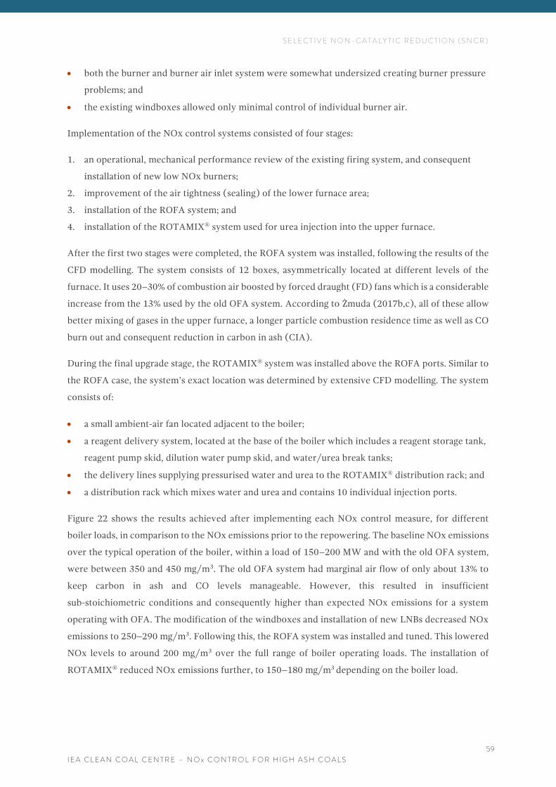
S E L E C T I V E N O N - C A T A L Y T I C R E D U C T I O N ( S N C R )
I E A C L E A N C O A L C E N T R E – N O x C O N T R O L F O R H I G H A S H C O A L S
59
• both the burner and burner air inlet system were somewhat undersized creating burner pressure
problems; and
• the existing windboxes allowed only minimal control of individual burner air.
Implementation of the NOx control systems consisted of four stages:
1. an operational, mechanical performance review of the existing firing system, and consequent
installation of new low NOx burners;
2. improvement of the air tightness (sealing) of the lower furnace area;
3. installation of the ROFA system; and
4. installation of the ROTAMIX® system used for urea injection into the upper furnace.
After the first two stages were completed, the ROFA system was installed, following the results of the
CFD modelling. The system consists of 12 boxes, asymmetrically located at different levels of the
furnace. It uses 20–30% of combustion air boosted by forced draught (FD) fans which is a considerable
increase from the 13% used by the old OFA system. According to Żmuda (2017b,c), all of these allow
better mixing of gases in the upper furnace, a longer particle combustion residence time as well as CO
burn out and consequent reduction in carbon in ash (CIA).
During the final upgrade stage, the ROTAMIX® system was installed above the ROFA ports. Similar to
the ROFA case, the system’s exact location was determined by extensive CFD modelling. The system
consists of:
• a small ambient-air fan located adjacent to the boiler;
• a reagent delivery system, located at the base of the boiler which includes a reagent storage tank,
reagent pump skid, dilution water pump skid, and water/urea break tanks;
• the delivery lines supplying pressurised water and urea to the ROTAMIX® distribution rack; and
• a distribution rack which mixes water and urea and contains 10 individual injection ports.
Figure 22 shows the results achieved after implementing each NOx control measure, for different
boiler loads, in comparison to the NOx emissions prior to the repowering. The baseline NOx emissions
over the typical operation of the boiler, within a load of 150–200 MW and with the old OFA system,
were between 350 and 450 mg/m3. The old OFA system had marginal air flow of only about 13% to
keep carbon in ash and CO levels manageable. However, this resulted in insufficient
sub-stoichiometric conditions and consequently higher than expected NOx emissions for a system
operating with OFA. The modification of the windboxes and installation of new LNBs decreased NOx
emissions to 250–290 mg/m3. Following this, the ROFA system was installed and tuned. This lowered
NOx levels to around 200 mg/m3 over the full range of boiler operating loads. The installation of
ROTAMIX® reduced NOx emissions further, to 150–180 mg/m3 depending on the boiler load.
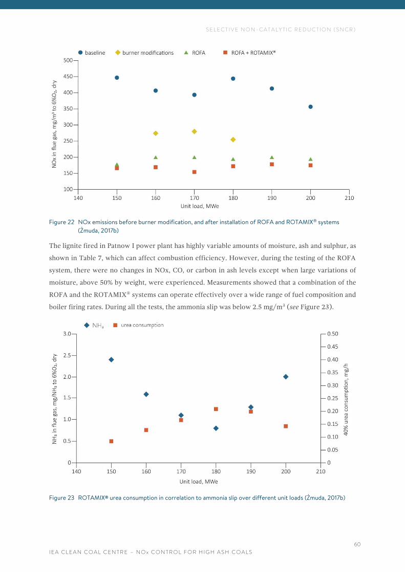
S E L E C T I V E N O N - C A T A L Y T I C R E D U C T I O N ( S N C R )
I E A C L E A N C O A L C E N T R E – N O x C O N T R O L F O R H I G H A S H C O A L S
60
Figure 22 NOx emissions before burner modification, and after installation of ROFA and ROTAMIX® systems
(Żmuda, 2017b)
The lignite fired in Patnow I power plant has highly variable amounts of moisture, ash and sulphur, as
shown in Table 7, which can affect combustion efficiency. However, during the testing of the ROFA
system, there were no changes in NOx, CO, or carbon in ash levels except when large variations of
moisture, above 50% by weight, were experienced. Measurements showed that a combination of the
ROFA and the ROTAMIX® systems can operate effectively over a wide range of fuel composition and
boiler firing rates. During all the tests, the ammonia slip was below 2.5 mg/m3 (see Figure 23).
Figure 23 ROTAMIX® urea consumption in correlation to ammonia slip over different unit loads (Żmuda, 2017b)
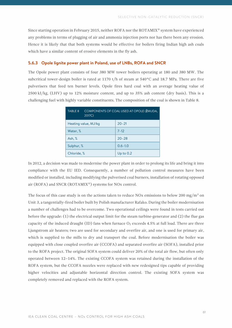
S E L E C T I V E N O N - C A T A L Y T I C R E D U C T I O N ( S N C R )
I E A C L E A N C O A L C E N T R E – N O x C O N T R O L F O R H I G H A S H C O A L S
61
Since starting operation in February 2015, neither ROFA nor the ROTAMIX® system have experienced
any problems in terms of plugging of air and ammonia injection ports nor has there been any erosion.
Hence it is likely that that both systems would be effective for boilers firing Indian high ash coals
which have a similar content of erosive elements in the fly ash.
5.6.3 Opole lignite power plant in Poland, use of LNBs, ROFA and SNCR
The Opole power plant consists of four 380 MW tower boilers operating at 180 and 380 MW. The
subcritical tower-design boiler is rated at 1170 t/h of steam at 540°C and 18.7 MPa. There are five
pulverisers that feed ten burner levels. Opole fires hard coal with an average heating value of
2500 kJ/kg, (LHV) up to 12% moisture content, and up to 35% ash content (dry basis). This is a
challenging fuel with highly variable constituents. The composition of the coal is shown in Table 8.
TABLE 8 COMPONENTS OF COAL USED AT OPOLE (ŻMUDA,
2017C)
Heating value, MJ/kg 20–21
Water, % 7–12
Ash, % 20–28
Sulphur, % 0.6–1.0
Chloride, % Up to 0.2
In 2012, a decision was made to modernise the power plant in order to prolong its life and bring it into
compliance with the EU IED. Consequently, a number of pollution control measures have been
modified or installed, including modifying the pulverised coal burners, installation of rotating opposed
air (ROFA) and SNCR (ROTAMIX®) systems for NOx control.
The focus of this case study is on the actions taken to reduce NOx emissions to below 200 mg/m3 on
Unit 3, a tangentially-fired boiler built by Polish manufacturer Rafako. During the boiler modernisation
a number of challenges had to be overcome. Two operational ceilings were found in tests carried out
before the upgrade: (1) the electrical output limit for the steam turbine-generator and (2) the flue gas
capacity of the induced draught (ID) fans when furnace O2 exceeds 4.5% at full load. There are three
Ljungstrom air heaters; two are used for secondary and overfire air, and one is used for primary air,
which is supplied to the mills to dry and transport the coal. Before modernisation the boiler was
equipped with close coupled overfire air (CCOFA) and separated overfire air (SOFA), installed prior
to the ROFA project. The original SOFA system could deliver 20% of the total air flow, but often only
operated between 12–14%. The existing CCOFA system was retained during the installation of the
ROFA system, but the CCOFA nozzles were replaced with new redesigned tips capable of providing
higher velocities and adjustable horizontal direction control. The existing SOFA system was
completely removed and replaced with the ROFA system.
S E L E C T I V E N O N - C A T A L Y T I C R E D U C T I O N ( S N C R )
I E A C L E A N C O A L C E N T R E – N O x C O N T R O L F O R H I G H A S H C O A L S
62
Implementation of NOx control systems consisted of:
• reviewing the pulverisers and coal feed system to validate operational performance and the fuel
distribution to individual burners;
• installation of the ROFA system; and
• installation of the ROTAMIX® system used for urea injection into the upper furnace.
The existing burners and secondary air (SA) nozzles had compartmental tilt control, but it was manual
and was not often utilised during the day-to-day operation of the boiler. The manual tilt control was
replaced by an automated SA nozzle tilt system in order to allow control of the superheat (SH) and
reheat (RH) temperature. The existing CCOFA ports were replaced with new higher velocity nozzles
which also provided manual control for both tilt (vertical) and yaw (horizontal).
The ROFA system was installed to lower NOx through furnace staging. The ROFA system has been
designed to increase mixing in the upper furnace for CO and LOI burnout. The ROFA system includes
a boosted-pressure ROFA fan air ducting, and air injection nozzles. ROFA air is taken from ducts at the
outlet of the air preheater boosted under pressure by the ROFA fan and delivered through nozzles into
the furnace. The air pressure at the nozzles is optimised as necessary to achieve that determined by
the CFD modelling. All the ROFA nozzles are controlled based on the boiler steam flow to maintain
tuned box pressures load changes. Additionally, feed-forward and feed-back control strategies can be
implemented to reduce system upsets during load fluctuations.
The ROTAMIX® system consists of an air delivery system and a liquid (urea and water) delivery
system. Since the system utilises ambient temperature air, ductwork is reduced and the need for
thermal insulation is removed. Urea can also be injected through the ROFA nozzles. The upper furnace
injection points have injection angle adjustment capability.
Figure 24 shows the results achieved after implementing each NOx control measure, for different
boiler loads, in comparison to the NOx emissions prior to the repowering. The baseline NOx emissions
over the typical operation of the boiler, within a load of 180–370 MW and with the old overfire air
(SOFA), were between 450–470 mg/m3. The modification of the windboxes and installation of new
LNBs decreased NOx emissions to 350–380 mg/m3. The tuned ROFA system allows NOx emissions to
be reduced to about 220 mg/m3 over the full range of boiler operating loads. The installation of
ROTAMIX® reduced NOx emissions further, to 150–180 mg/m3 depending on the boiler load.
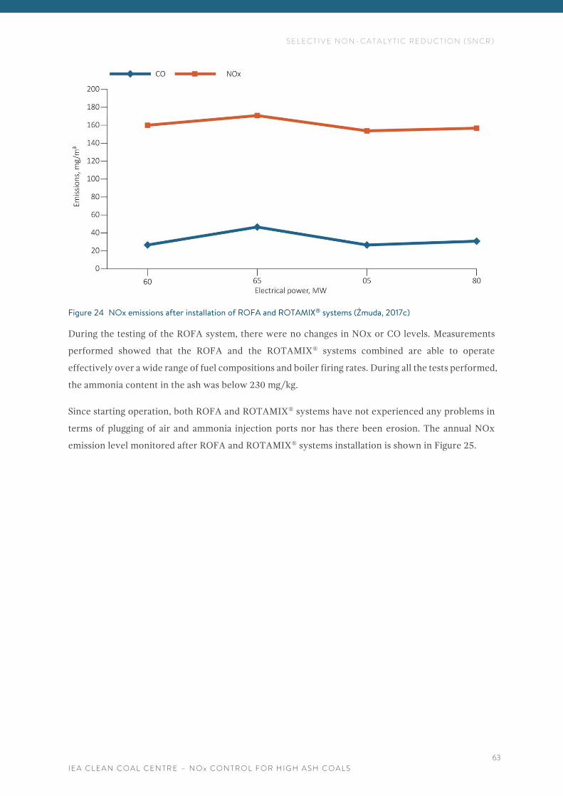
S E L E C T I V E N O N - C A T A L Y T I C R E D U C T I O N ( S N C R )
I E A C L E A N C O A L C E N T R E – N O x C O N T R O L F O R H I G H A S H C O A L S
63
Figure 24 NOx emissions after installation of ROFA and ROTAMIX® systems (Żmuda, 2017c)
During the testing of the ROFA system, there were no changes in NOx or CO levels. Measurements
performed showed that the ROFA and the ROTAMIX® systems combined are able to operate
effectively over a wide range of fuel compositions and boiler firing rates. During all the tests performed,
the ammonia content in the ash was below 230 mg/kg.
Since starting operation, both ROFA and ROTAMIX® systems have not experienced any problems in
terms of plugging of air and ammonia injection ports nor has there been erosion. The annual NOx
emission level monitored after ROFA and ROTAMIX® systems installation is shown in Figure 25.
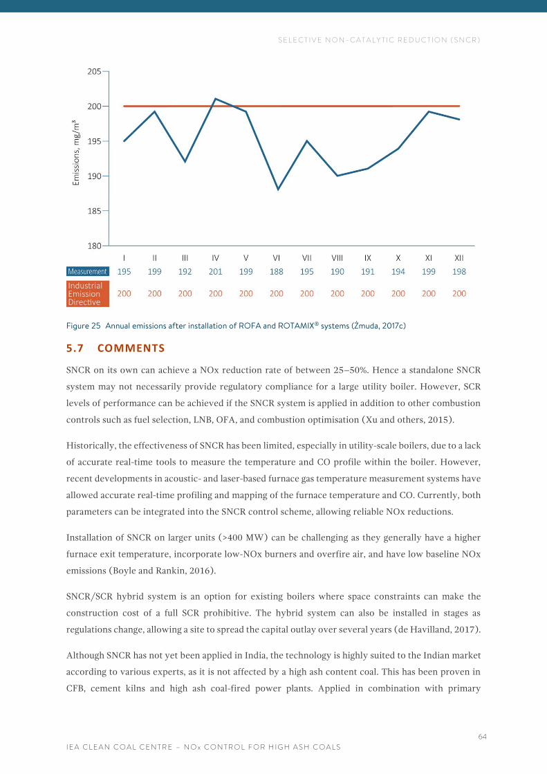
S E L E C T I V E N O N - C A T A L Y T I C R E D U C T I O N ( S N C R )
I E A C L E A N C O A L C E N T R E – N O x C O N T R O L F O R H I G H A S H C O A L S
64
Figure 25 Annual emissions after installation of ROFA and ROTAMIX® systems (Żmuda, 2017c)
5.7 COMMENTS
SNCR on its own can achieve a NOx reduction rate of between 25–50%. Hence a standalone SNCR
system may not necessarily provide regulatory compliance for a large utility boiler. However, SCR
levels of performance can be achieved if the SNCR system is applied in addition to other combustion
controls such as fuel selection, LNB, OFA, and combustion optimisation (Xu and others, 2015).
Historically, the effectiveness of SNCR has been limited, especially in utility-scale boilers, due to a lack
of accurate real-time tools to measure the temperature and CO profile within the boiler. However,
recent developments in acoustic- and laser-based furnace gas temperature measurement systems have
allowed accurate real-time profiling and mapping of the furnace temperature and CO. Currently, both
parameters can be integrated into the SNCR control scheme, allowing reliable NOx reductions.
Installation of SNCR on larger units (>400 MW) can be challenging as they generally have a higher
furnace exit temperature, incorporate low-NOx burners and overfire air, and have low baseline NOx
emissions (Boyle and Rankin, 2016).
SNCR/SCR hybrid system is an option for existing boilers where space constraints can make the
construction cost of a full SCR prohibitive. The hybrid system can also be installed in stages as
regulations change, allowing a site to spread the capital outlay over several years (de Havilland, 2017).
Although SNCR has not yet been applied in India, the technology is highly suited to the Indian market
according to various experts, as it is not affected by a high ash content coal. This has been proven in
CFB, cement kilns and high ash coal-fired power plants. Applied in combination with primary
S E L E C T I V E N O N - C A T A L Y T I C R E D U C T I O N ( S N C R )
I E A C L E A N C O A L C E N T R E – N O x C O N T R O L F O R H I G H A S H C O A L S
65
measures, an SNCR is an option for Indian plants which are required to reduce their emissions of NOx
to 300 mg/ m3. It can be also applied in combination with a small SCR, which is expected to lower the
operating cost of SCR as well as prolong the catalyst life. Hence, hybrid systems, in combination with
primary measures, would be candidates for units with NOx emission limits of 300 mg/m3 as well as
those with 100 mg/m3 limits.
The advantages of SNCR include its applicability to a wide range of boiler sizes (up to 800–900 MW),
its quick and relatively easy installation, and applicability to units with space constraints. Additionally,
in contrast to SCR, most SNCR systems use urea without converting it to ammonia. The use of urea,
rather than ammonia, reduces the environmental and health hazards, and gives more effective NOx
removal on larger boilers, over 400 MW in size.
Although SNCR can be retrofitted relatively easily, it is unlikely that it will be applied in Indian boilers
before 2019. This is because Indian utilities will need a considerable time to prepare for the upgrade
or retrofit of other pollutant controls such as FGD and ESP. Further there is a lack of experience in the
use of SNCR and many plants may wish to wait to see results from pilot tests with SCR and SNCR,
which are currently being carried out in eight NTPC units and are expected to be finished in 2019.
M U L T I - P O L L U T A N T A N D E M E R G I N G N O x C O N T R O L T E C H N O L O G I E S
I E A C L E A N C O A L C E N T R E – N O x C O N T R O L F O R H I G H A S H C O A L S
66
6 M U L T I - P O L L U T A N T A N D E M E R G I N G N O x
C O N T R O L T E C H N O L O G I E S
The definition of a multi-pollutant control system can be confusing because all pollution control
systems offer the potential to reduce a number of pollutants simultaneously. In recent years, many
technologies have emerged into the market which are defined commercially as multi-pollutant control
systems. Although many of these systems can be used to remove several pollutants simultaneously,
such as particulates PM, SOx and NOx, this does not seem to be happening. On the contrary, most
multi-pollutant systems appear to be sold for use as an addition to the usual control systems, such as
FGD, ESP, SCR, with the aim to reduce emissions of specific pollutants further (Sloss, 2017).
There are a few multi-pollutant systems which can remove NOx. Some of them, such as ReACT™ have
been used in coal-fired power plants for several years, notably at full scale in Japan since the 1990s.
Others are deployed in non-coal applications but have the potential to be applied to coal-fired plants
and are in various stages of testing and demonstration.
6.1 REACT™
ReACT™ is a regenerative activated coke dry-type capture technology that captures SOx, NOx and
mercury while only using 1% of the water required by conventional wet FGD. ReACT™ can be
configured for different levels of NOx control, described as:
• co-benefit NOx control at 20–50%;
• enhanced NOx control of 40–60% with ammonia dosed activated carbon regeneration; and
• higher NOx control to 80% is available with two-stage adsorption.
Figure 26 shows a schematic flow diagram of the ReACT™ system with single-stage adsorption and
Figure 27 shows the ReACT™ system with a two-stage adsorber configuration.
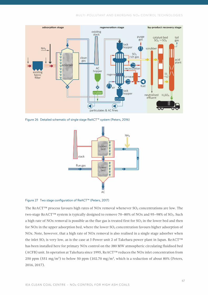
M U L T I - P O L L U T A N T A N D E M E R G I N G N O x C O N T R O L T E C H N O L O G I E S
I E A C L E A N C O A L C E N T R E – N O x C O N T R O L F O R H I G H A S H C O A L S
67
Figure 26 Detailed schematic of single stage ReACT™ system (Peters, 2016)
Figure 27 Two stage configuration of ReACT™ (Peters, 2017)
The ReACT™ process favours high rates of NOx removal whenever SO2 concentrations are low. The
two-stage ReACT™ system is typically designed to remove 70–80% of NOx and 95–98% of SO2. Such
a high rate of NOx removal is possible as the flue gas is treated first for SO2 in the lower bed and then
for NOx in the upper adsorption bed, where the lower SO2 concentration favours higher adsorption of
NOx. Note, however, that a high rate of NOx removal is also realised in a single stage adsorber when
the inlet SO2 is very low, as is the case at J-Power unit 2 of Takehara power plant in Japan. ReACT™
has been installed here for primary NOx control on the 380 MW atmospheric circulating fluidised bed
(ACFB) unit. In operation at Takehara since 1995, ReACT™ reduces the NOx inlet concentration from
250 ppm (551 mg/m3) to below 50 ppm (102.70 mg/m3, which is a reduction of about 80% (Peters,
2016, 2017).
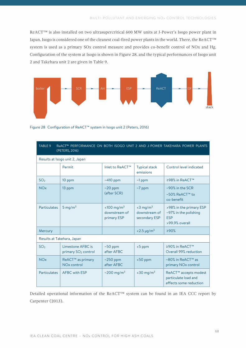
M U L T I - P O L L U T A N T A N D E M E R G I N G N O x C O N T R O L T E C H N O L O G I E S
I E A C L E A N C O A L C E N T R E – N O x C O N T R O L F O R H I G H A S H C O A L S
68
ReACT™ is also installed on two ultrasupercritical 600 MW units at J-Power’s Isogo power plant in
Japan. Isogo is considered one of the cleanest coal-fired power plants in the world. There, the ReACT™
system is used as a primary SOx control measure and provides co-benefit control of NOx and Hg.
Configuration of the system at Isogo is shown in Figure 28, and the typical performances of Isogo unit
2 and Takehara unit 2 are given in Table 9.
Figure 28 Configuration of ReACT™ system in Isogo unit 2 (Peters, 2016)
TABLE 9 ReACT™ PERFORMANCE ON BOTH ISOGO UNIT 2 AND J-POWER TAKEHARA POWER PLANTS
(PETERS, 2016)
Results at Isogo unit 2, Japan
Permit Inlet to ReACT™ Typical stack
emissions
Control level indicated
SO2 10 ppm ~410 ppm ~1 ppm ≥98% in ReACT™
NOx 13 ppm ~20 ppm
(after SCR)
~7 ppm ~90% in the SCR
~50% ReACT™ to
co-benefit
Particulates 5 mg/m3 <100 mg/m3
downstream of
primary ESP
<3 mg/m3
downstream of
secondary ESP
>98% in the primary ESP
~97% in the polishing
ESP
>99.9% overall
Mercury <2.5 µg/m3 ≥90%
Results at Takehara, Japan
SO2 Limestone AFBC is
primary SO2 control
~50 ppm
after AFBC
<5 ppm ≥90% in ReACT™
Overall 99% reduction
NOx ReACT™ as primary
NOx control
~250 ppm
after AFBC
<50 ppm ~80% in ReACT™ as
primary NOx control
Particulates AFBC with ESP ~200 mg/m3 <30 mg/m3 ReACT™ accepts modest
particulate load and
effects some reduction
Detailed operational information of the ReACT™ system can be found in an IEA CCC report by
Carpenter (2013).
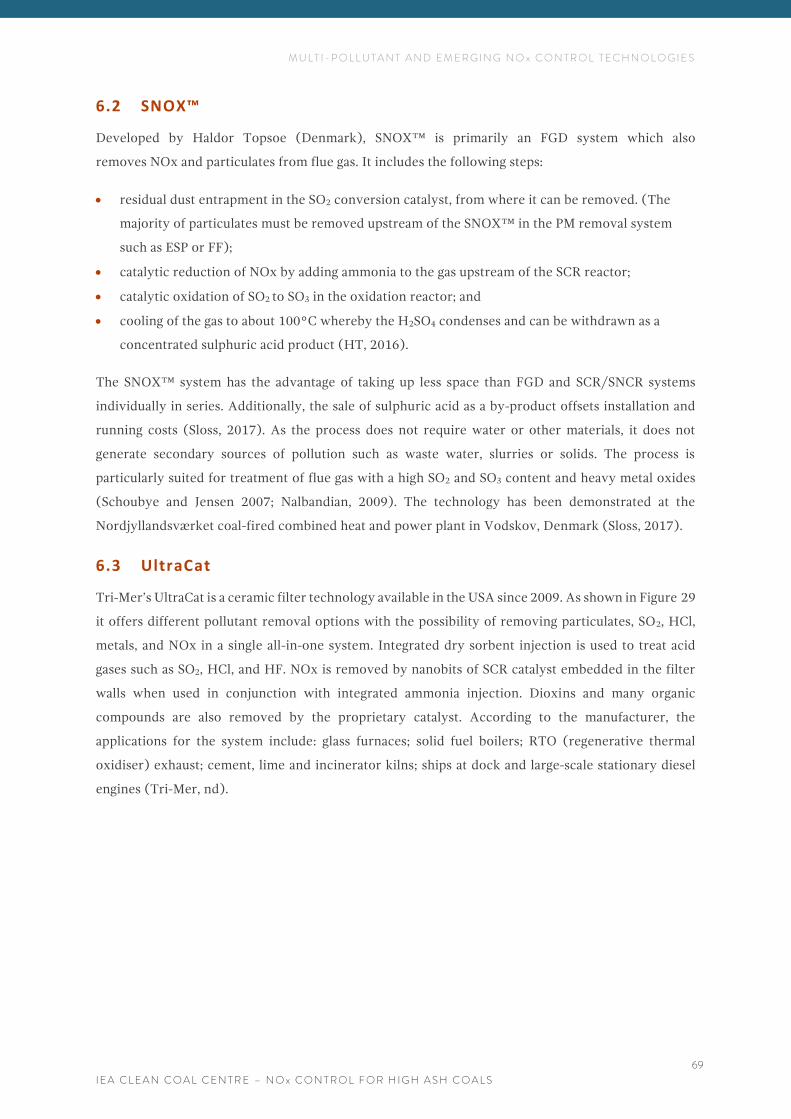
M U L T I - P O L L U T A N T A N D E M E R G I N G N O x C O N T R O L T E C H N O L O G I E S
I E A C L E A N C O A L C E N T R E – N O x C O N T R O L F O R H I G H A S H C O A L S
69
6.2 SNOX™
Developed by Haldor Topsoe (Denmark), SNOX™ is primarily an FGD system which also
removes NOx and particulates from flue gas. It includes the following steps:
• residual dust entrapment in the SO2 conversion catalyst, from where it can be removed. (The
majority of particulates must be removed upstream of the SNOX™ in the PM removal system
such as ESP or FF);
• catalytic reduction of NOx by adding ammonia to the gas upstream of the SCR reactor;
• catalytic oxidation of SO2 to SO3 in the oxidation reactor; and
• cooling of the gas to about 100°C whereby the H2SO4 condenses and can be withdrawn as a
concentrated sulphuric acid product (HT, 2016).
The SNOX™ system has the advantage of taking up less space than FGD and SCR/SNCR systems
individually in series. Additionally, the sale of sulphuric acid as a by-product offsets installation and
running costs (Sloss, 2017). As the process does not require water or other materials, it does not
generate secondary sources of pollution such as waste water, slurries or solids. The process is
particularly suited for treatment of flue gas with a high SO2 and SO3 content and heavy metal oxides
(Schoubye and Jensen 2007; Nalbandian, 2009). The technology has been demonstrated at the
Nordjyllandsværket coal-fired combined heat and power plant in Vodskov, Denmark (Sloss, 2017).
6.3 UltraCat
Tri-Mer’s UltraCat is a ceramic filter technology available in the USA since 2009. As shown in Figure 29
it offers different pollutant removal options with the possibility of removing particulates, SO2, HCl,
metals, and NOx in a single all-in-one system. Integrated dry sorbent injection is used to treat acid
gases such as SO2, HCl, and HF. NOx is removed by nanobits of SCR catalyst embedded in the filter
walls when used in conjunction with integrated ammonia injection. Dioxins and many organic
compounds are also removed by the proprietary catalyst. According to the manufacturer, the
applications for the system include: glass furnaces; solid fuel boilers; RTO (regenerative thermal
oxidiser) exhaust; cement, lime and incinerator kilns; ships at dock and large-scale stationary diesel
engines (Tri-Mer, nd).
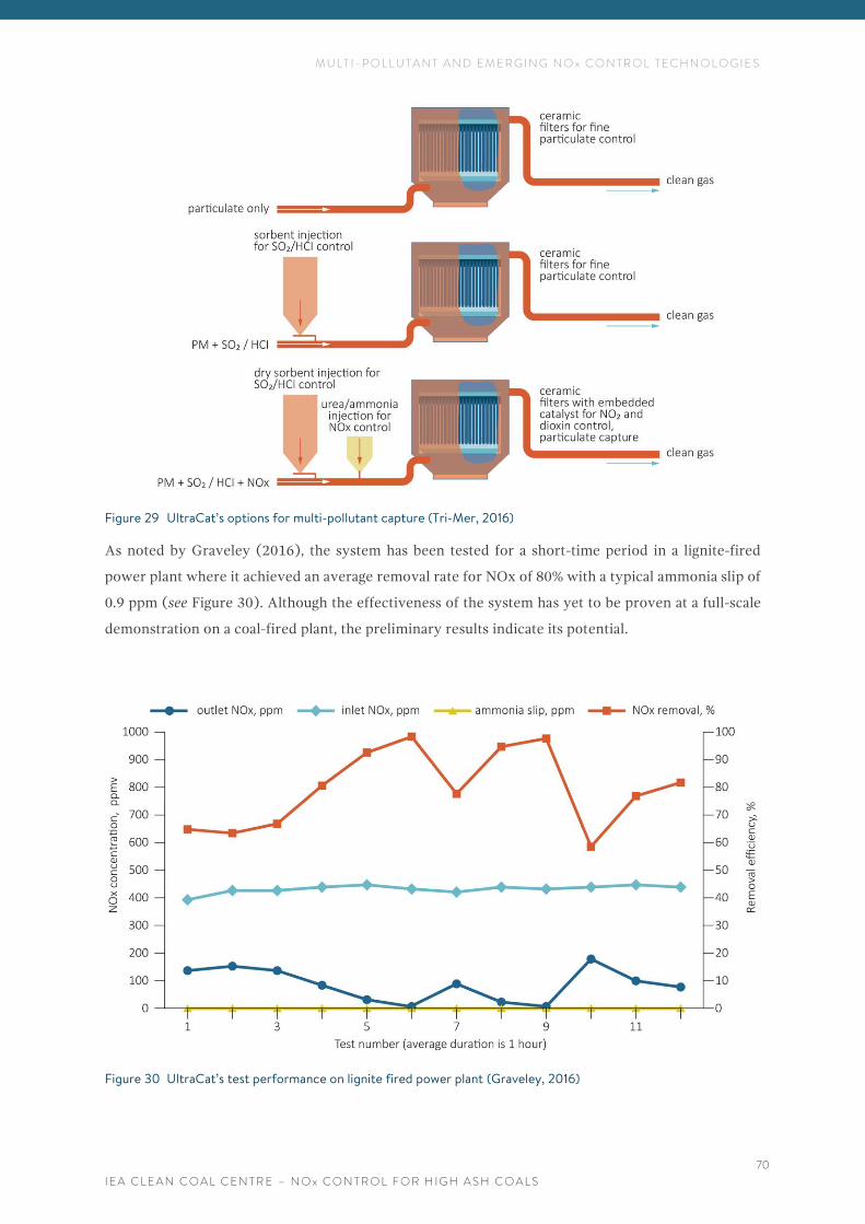
M U L T I - P O L L U T A N T A N D E M E R G I N G N O x C O N T R O L T E C H N O L O G I E S
I E A C L E A N C O A L C E N T R E – N O x C O N T R O L F O R H I G H A S H C O A L S
70
Figure 29 UltraCat’s options for multi-pollutant capture (Tri-Mer, 2016)
As noted by Graveley (2016), the system has been tested for a short-time period in a lignite-fired
power plant where it achieved an average removal rate for NOx of 80% with a typical ammonia slip of
0.9 ppm (see Figure 30). Although the effectiveness of the system has yet to be proven at a full-scale
demonstration on a coal-fired plant, the preliminary results indicate its potential.
Figure 30 UltraCat’s test performance on lignite fired power plant (Graveley, 2016)
M U L T I - P O L L U T A N T A N D E M E R G I N G N O x C O N T R O L T E C H N O L O G I E S
I E A C L E A N C O A L C E N T R E – N O x C O N T R O L F O R H I G H A S H C O A L S
71
6.4 LOTOX™
Linde’s patented LoTOx™ process uses low-temperature ozone injection to oxidise NOx to
highly-soluble dinitrogen pentoxide (N2O5) for capture in an FGD system, where the flue gas moisture
and the liquid convert it to nitric acid (HNO3). The conversion of the N2O5 into the aqueous phase is
rapid (0.25 seconds at 150°C) and irreversible, resulting in near-complete removal of NOx (URS
Corporation, 2014). The system can also be used with a dry FGD system (Stapper, 2017). This
technology has been applied in the oil refining sector on more than 30 units installed on a 25 MW
coal-fired institutional boiler and it has been tested as part of an EPRI pilot demonstration on a
550 MW coal-fired plant. It can provide 90% NOx reduction (McIlavine, 2016; Liu and all, 2016). In
LoTOx™ applications, ozone is produced onsite bypassing oxygen through a conventional ozone
generator, so no ozone storage is required. The ozone is generated ‘on demand’, depending on the NOx
level present in the flue gas and the required removal efficiency. According to AECOM (2016), Linde’s
licensee for the US power industry, ‘the implementation of LoTOx™ requires less capital investment
and has fewer operating constraints, making it a cost-effective alternative to SCR on boilers with low
baseline NOx emissions, modest capacity factors and uncertain futures’. This is because, in comparison
to a SCR system, the LoTOx™ process has:
• no catalyst, hence no deactivation occurs and there is no need for periodic outage for catalyst
cleaning or replacement;
• no minimum temperature constraints;
• no air heater (AH) fouling;
• no ammonia storage and handling;
• a reduced requirement for duct modification;
• no fan upgrade is required; and
• shorter outage is needed for installation (Liu and others, 2016).
According to Liu and others (2015), the system has the additional advantages of being able to achieve
mercury oxidation rates of 50–70%, as well as not converting SO2 to SO3. Like many other NOx control
measures, the system can be used in combination with other NOx control technologies. For example,
when it is used in combination with rotating opposed fire air (ROFA), it can provide effective NOx
control for units firing lignite with a high sodium content, such as North Dakota lignite. In this situation,
an SCR may not be an option due to sodium causing blinding on the surface of the catalyst (URS
Corporation, 2014). Also, the combined system may allow the use of less expensive, higher sulphur
coal without having to take into consideration the detrimental effects of deposition and SO3 that may
occur on a unit using an SCR. When combined with the ROFA and the ROTAMIX®, the LoTOx™ can
provide 75–95% NOx reduction (Liu and others, 2016). However, the system has yet to be
commercially deployed in a coal-fired power plant to ascertain its operational performance.
M U L T I - P O L L U T A N T A N D E M E R G I N G N O X C O N T R O L T E C H N O L O G I E S
I E A C L E A N C O A L C E N T R E – N O x C O N T R O L F O R H I G H A S H C O A L S
72
6.5 MULTI-POLLUTANT AND EMERGING NOx CONTROL METHODS FOR HIGH ASH COALS
As noted by Sloss (2017) pollution control technologies are expensive and require significant time to
install, which in turn means disrupting power generation. Particularly in the case of India, which
already experiences power shortages, it would make sense to coordinate installation of pollution
control systems and to focus on multi-pollutant control systems.
Although, there are no multi-pollutant systems developed specifically for high ash coals, it appears that
the existing ones can be applied successfully. For India, both cost and water availability are important
considerations in the technology selection process.
According to Peters (2017), as the ReACT™ technology (see Section 6.1) is placed downstream of the
ESP, the system is not subject to fly ash loading and is suitable for units firing high ash coals. For such
applications, it can be used in a single stage configuration, which allows removal of about 50% of the
NOx. Alternatively, depending on economic and performance factors, it can be used in a ‘two-stage’
configuration which enables NOx control of up to 80%. Typically, the inlet NOx concentration will be
in the range of 250 ppm (dry basis) (~550 mg/m3) or lower for ReACT™ applications. This level of
concentration of NOx is achieved easily in coal-fired units with low NOx burners.
The ReACT™ system can be installed on new and retrofit projects, and appears to be advantageous
especially for units located where water use is an issue. In retrofit applications, a single stage ReACT™
can provide a feasible solution in addition to low NOx burners and/or overfire air systems. A two-stage
ReACT™ application would also be an option for new power plants using Indian coal, as an alternative
to SCR technology, again if installed in addition to LNBs and other primary measures. The system has
other advantages which are relevant to the Indian market such as: it minimises waste; revenue can be
derived from the by-products of fly ash and sulphuric acid; and the system is operational through
start-up and shutdown. As noted by Peters (2017), the system can be considered as a ‘retrofit’
technology that minimises station outage requirements for construction, since the ReACT™
equipment is located downstream of the plant’s existing equipment and can be tied back into the
existing stack.
The potential of the ReACT™ system for Indian high ash coals has been already recognised by the
Indian Government and utilities (NRPC, 2017).
Many existing Indian plants must install FGD units to comply with the new SO2 standards of 200
mg/m3. Units larger than 500 MW with a space provision for such systems have already been identified.
It has been estimated that pre-installation activities should take about three years, until around 2020.
During this period, it has been recommended that other pollution control measures such as LNBs and
overfire air can be installed in the nearest outages (NRPC, 2017; SRPC, 2017). For plants where a wet
FGD system is selected, following installation of primary NOx measures such as LNBs or OFA, it may

M U L T I - P O L L U T A N T A N D E M E R G I N G N O X C O N T R O L T E C H N O L O G I E S
I E A C L E A N C O A L C E N T R E – N O x C O N T R O L F O R H I G H A S H C O A L S
73
be worth considering installation of the LoTOx™ system, described in Section 6.4, as an alternative to
an SNCR or SCR. This is because the LoTOx™ system will allow removal of NOx and oxidised mercury
in a wet scrubber and should not be affected by the high ash content. It will also remove the need for
storage and handling of an ammonia reagent and consequently should save both space and water, as
well as potentially bringing the cost of NOx control down.
Other multi-pollutant controls and emerging systems may also have potential in Indian plants too,
especially those which minimise water usage and cost.
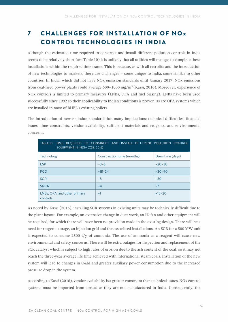
C H A L L E N G E S F O R I N S T A L L A T I O N O F N O x C O N T R O L T E C H N O L O G I E S I N I N D I A
I E A C L E A N C O A L C E N T R E – N O x C O N T R O L F O R H I G H A S H C O A L S
74
7 C H A L L E N G E S F O R I N S T A L L A T I O N O F N O x
C O N T R O L T E C H N O L O G I E S I N I N D I A
Although the estimated time required to construct and install different pollution controls in India
seems to be relatively short (see Table 10) it is unlikely that all utilities will manage to complete these
installations within the required time frame. This is because, as with all retrofits and the introduction
of new technologies to markets, there are challenges – some unique to India, some similar to other
countries. In India, which did not have NOx emission standards until January 2017, NOx emissions
from coal-fired power plants could average 600–1000 mg/m3 (Kassi, 2016). Moreover, experience of
NOx controls is limited to primary measures (LNBs, OFA and fuel biasing). LNBs have been used
successfully since 1992 so their applicability to Indian conditions is proven, as are OFA systems which
are installed in most of BHEL’s existing boilers.
The introduction of new emission standards has many implications: technical difficulties, financial
issues, time constraints, vendor availability, sufficient materials and reagents, and environmental
concerns.
TABLE 10 TIME REQUIRED TO CONSTRUCT AND INSTALL DIFFERENT POLLUTION CONTROL
EQUIPMENT IN INDIA (CSE, 2016)
Technology Construction time (months) Downtime (days)
ESP ~3–6 ~20–30
FGD ~18–24 ~30–90
SCR ~5 ~30
SNCR ~4 ~7
LNBs, OFA, and other primary
controls
~1 ~15–20
As noted by Kassi (2016), installing SCR systems in existing units may be technically difficult due to
the plant layout. For example, an extensive change in duct work, an ID fan and other equipment will
be required, for which there will have been no provision made in the existing design. There will be a
need for reagent storage, an injection grid and the associated installations. An SCR for a 500 MW unit
is expected to consume 2500 t/y of ammonia. The use of ammonia as a reagent will cause new
environmental and safety concerns. There will be extra outages for inspection and replacement of the
SCR catalyst which is subject to high rates of erosion due to the ash content of the coal, so it may not
reach the three-year average life time achieved with international steam coals. Installation of the new
system will lead to changes in O&M and greater auxiliary power consumption due to the increased
pressure drop in the system.
According to Kassi (2016), vendor availability is a greater constraint than technical issues. NOx control
systems must be imported from abroad as they are not manufactured in India. Consequently, the
C H A L L E N G E S F O R I N S T A L L A T I O N O F N O x C O N T R O L T E C H N O L O G I E S I N I N D I A
I E A C L E A N C O A L C E N T R E – N O x C O N T R O L F O R H I G H A S H C O A L S
75
installation of NOx control technology at a rate of 20,000 MW/y of plant for a total 256,000 MW
capacity (made up of 175,200 existing plus 80,800 MW under construction) would take more than
10 years.
If the initially announced two-year timeframe to implement new standards were to remain in place,
there would be considerable delays for some power plants (Kassi, 2016; Krishnan, 2016). There are
many reasons for this. For example, where construction of power plants started before the new limits
were introduced, the plants must be re-designed and so they may not come online as planned.
Consequently, the expected new capacity may not come to the grid on time, which will affect India’s
power supply and will have financial implications for the utilities. Additionally, there may be an impact
on the power supply due to plant outages for necessary modifications and retrofits to comply with
new standards.
These issues have been raised by the utilities who are concerned that two years is insufficient to
implement the new norms in view of the time required for design and engineering, approvals,
arrangement of funds, tendering and erection, testing and commissioning. Recently, revised
implementation plans have been issued for FGD installation and many units have individual deadlines
for installation of other controls (Bureau, 2018). Further, units which operate in intermittent and/or
seasonal mode will be unlikely to recover the huge investment required during their remaining life
span without a considerable increase in energy tariffs. Additionally, postponing commissioning of the
units which are currently under construction, due to the new standards, may lead to contractual
problems with equipment suppliers, establishment of guarantees and many more issues (Kassi, 2016).
As noted by Kassi (2016), there is a limited supply of desulphurisation systems and no supplier of
post-combustion NOx control systems proven to operate in Indian conditions, so, ‘excessive outflow of
foreign exchange shall take place’. This could mean a sharp increase in prices due to high demand within
a short timescale. Consequently, the energy tariff may increase by an estimated 45–55 paise/kWh
(Rs 0 45–0.55 or US$0.01). For 15–20-year old plants, even a sharp increase in tariffs may not allow
recovery of the investment in their remaining lifetime.
According to Krishnan (2016), and contrary to Kassi’s opinion on vendor availability and possible
equipment prices, competition among pollution control manufacturers is ‘fierce’. Krishnan (2016)
states that there are more than 30 global suppliers of technology, including boilers and environmental
control systems active in the Indian market. As many global manufacturers are experiencing weak
demand worldwide for their air quality control systems, they are offering their technologies in India
‘at amongst the lowest prices’ in a bid to get a share of the market. Therefore, it can be expected that
the price for environmental equipment in India will be close to 50% of global prices. Consequently,
pollution control manufacturers may consider localised manufacturing to be competitive in the Indian
market.
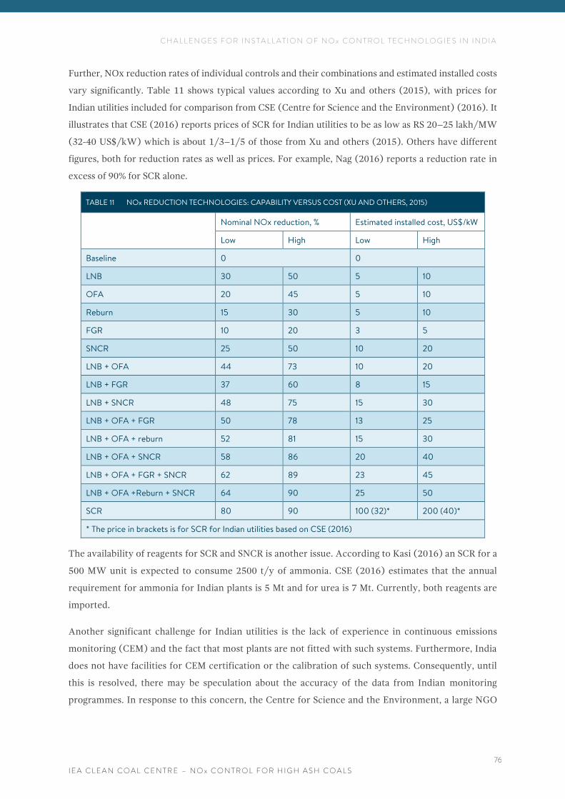
C H A L L E N G E S F O R I N S T A L L A T I O N O F N O x C O N T R O L T E C H N O L O G I E S I N I N D I A
I E A C L E A N C O A L C E N T R E – N O x C O N T R O L F O R H I G H A S H C O A L S
76
Further, NOx reduction rates of individual controls and their combinations and estimated installed costs
vary significantly. Table 11 shows typical values according to Xu and others (2015), with prices for
Indian utilities included for comparison from CSE (Centre for Science and the Environment) (2016). It
illustrates that CSE (2016) reports prices of SCR for Indian utilities to be as low as RS 20–25 lakh/MW
(32-40 US$/kW) which is about 1/3–1/5 of those from Xu and others (2015). Others have different
figures, both for reduction rates as well as prices. For example, Nag (2016) reports a reduction rate in
excess of 90% for SCR alone.
TABLE 11 NOx REDUCTION TECHNOLOGIES: CAPABILITY VERSUS COST (XU AND OTHERS, 2015)
Nominal NOx reduction, % Estimated installed cost, US$/kW
Low High Low High
Baseline 0 0
LNB 30 50 5 10
OFA 20 45 5 10
Reburn 15 30 5 10
FGR 10 20 3 5
SNCR 25 50 10 20
LNB + OFA 44 73 10 20
LNB + FGR 37 60 8 15
LNB + SNCR 48 75 15 30
LNB + OFA + FGR 50 78 13 25
LNB + OFA + reburn 52 81 15 30
LNB + OFA + SNCR 58 86 20 40
LNB + OFA + FGR + SNCR 62 89 23 45
LNB + OFA +Reburn + SNCR 64 90 25 50
SCR 80 90 100 (32)* 200 (40)*
* The price in brackets is for SCR for Indian utilities based on CSE (2016)
The availability of reagents for SCR and SNCR is another issue. According to Kasi (2016) an SCR for a
500 MW unit is expected to consume 2500 t/y of ammonia. CSE (2016) estimates that the annual
requirement for ammonia for Indian plants is 5 Mt and for urea is 7 Mt. Currently, both reagents are
imported.
Another significant challenge for Indian utilities is the lack of experience in continuous emissions
monitoring (CEM) and the fact that most plants are not fitted with such systems. Furthermore, India
does not have facilities for CEM certification or the calibration of such systems. Consequently, until
this is resolved, there may be speculation about the accuracy of the data from Indian monitoring
programmes. In response to this concern, the Centre for Science and the Environment, a large NGO
C H A L L E N G E S F O R I N S T A L L A T I O N O F N O x C O N T R O L T E C H N O L O G I E S I N I N D I A
I E A C L E A N C O A L C E N T R E – N O x C O N T R O L F O R H I G H A S H C O A L S
77
based in New Delhi, and the Source Testing Association of the UK produced the first technical
guidance manual for emissions monitoring in India (Sloss, 2018).
Despite several predicted obstacles there seems to be a determination to move forward with the
retrofits and new installations for NOx control. The largest Indian power utility, NTPC Ltd, and the
equipment manufacturer BHEL, have expressed an interest in pilot studies for NOx control
technologies (BHEL, 2016b). Currently, NTPC has eight pilot projects for installation of SCR and SNCR
technologies, with the results expected in 2019 (NRPC, 2017). BHEL is testing its own SCR catalyst on
a pilot scale and has also issued an Expression of Interest in which it seeks a response from original
SCR catalyst manufacturers willing to be associated with BHEL through a license and technology
collaboration agreement on a long-term basis. This is ‘to enable BHEL to design, engineer, manufacture,
assemble, test, supply, erect, commission, repair, service and retrofit the catalysts for SCR for NOx
reduction in high-dust flue gases from thermal power plants and other applications’ (BHEL, 2016b).
Similarly, foreign equipment manufacturers recognise the potential market in India and are developing
their systems to suit the requirements of Indian coals. For example, Doosan Babcock and Doosan
Heavy Industries recently developed low NOx burners specifically for such applications.
C O N C L U S I O N S
I E A C L E A N C O A L C E N T R E – N O x C O N T R O L F O R H I G H A S H C O A L S
78
8 C O N C L U S I O N S
Energy demand continues to grow in India, and the government has issued NOx emission standards
for both new and existing coal-fired thermal power plants. This has created opportunities for
equipment manufacturers, as well as a need for global technology leaders to modify their products to
meet the local market requirements, particularly so for compatibility with high ash content coal,
typical of India.
NOx controls are well proven, mature technologies, in use since the 1970s in countries with relevant
emission standards. However, as India, has only recently introduced NOx emission standards, some
of these technologies are regarded as novel and the utilities have little or no experience in their use.
The standards state that coal-fired units installed before 31 December 2003 must lower their emissions
to 600 mg/m3 which is not a challenging target and it has been reported that some units already comply
with this limit (CSE, 2016). The remaining plants can meet the limits by adding primary NOx control
measures such as low NOx burners and overfire air. Such measures are recommended to be
implemented over the next scheduled outages (SRPC, 2017; NRPC, 2017).
Plants which came online between 1 January 2004 and 31 December 2016 (a capacity of 121.3 GW)
must comply with a NOx emission limit of 300 mg/m3. According to the CPCB (Central Pollution
Control Board), some plants already meet these limits as manufacturers, including BHEL, supply
boilers that comply (CSE, 2016). However, for most of the units this creates a need to install both
primary and secondary control measures. Although it is likely that a combination of some primary
measures, such as LNBs developed specifically for Indian coals and OFA, may reduce NOx emissions
to 300 mg/m3 or less on some units, most boilers will require additional technologies such as SCR,
SNCR, or multi-pollutant systems.
New power plants which come online after 1 January 2017 are required to achieve a NOx emission
target of 100 mg/m3. This will require both primary and secondary measures.
Retrofit of primary measures has been recommended to take place during next scheduled plant outages,
and for many plants this could occur by 2019 (CSE, 2017). As reported by CSE (2017), in 2017, outages
for maintenance and overhauling works were scheduled for about 82.6 GW of the coal capacity. Of
these, the outage duration for about 7% of the capacity was less than ten days, which may not be
sufficient. In these cases, CSE has recommended that the outage duration be expanded accordingly.
For those units that have retrofitting scheduled during annual maintenance, all required modifications
for primary NOx controls must be executed during 2017–18. For the remaining 48 % of the capacity,
outages must be planned between April and December 2018 (CSE, 2017).
Major outages may be required on some units due to technical difficulties. In any case, retrofitting
primary measures such as LNBs and OFA must be carried out to avoid negative impacts on boiler
C O N C L U S I O N S
I E A C L E A N C O A L C E N T R E – N O x C O N T R O L F O R H I G H A S H C O A L S
79
operations. Combustion conditions should be monitored and controlled so there is no loss in boiler
efficiency or increase in pollutant emissions. This can be challenging for Indian utilities as there is little
experience in continuous emissions monitoring.
In terms of secondary NOx control installations, the results from pilot tests of SCR and SNCR on NTPC
units will not be known before 2019, so utilities are not expected to make decisions before the outcome
of these tests is clear (SRPC, 2017; NRPC, 2017). It may be years before the exact effect is known of
Indian coals on these systems. Hence contracts with potential suppliers should have some flexibility
and there should be provisions for future possible technical changes.
Although, there is lack of SCR and SNCR commercial installations in India, the experience from high
ash lignite-fired plants as well as from high-dust industries such as cement kilns, and CFB (in the case
of SNCR) plus initial results from demonstrations in India, indicate the potential of these technologies
for NOx reduction in high ash coal applications. Consequently, vendors have high confidence in the
applicability of their system to Indian plants.
NOx control systems as LNBs, SCR and SNCR as well as reagents and materials are not manufactured
in India and so must currently be imported.
As India is introducing emission standards for other pollutants, and pollution control technologies are
expensive and require significant time to install, which in turn means disrupting power generation, it
would make sense to co-ordinate installation of pollution control systems and to focus on
multi-pollutant control systems (Sloss, 2017). It appears that existing multi-pollutant and emerging
NOx controls could be applied successfully to Indian coals. Such systems can be installed on new and
retrofit projects and their potential has been already recognised by the Indian Government and utilities
(NRPC, 2017).
Choosing appropriate NOx control systems for any power plant requires a site-specific strategy which,
apart from cost, performance and safety, should also consider water availability. The challenge facing
Indian utilities is huge, but there seems to be a determination to move forward with retrofits and new
installations for NOx control.
R E F E R E N C E S
I E A C L E A N C O A L C E N T R E – N O x C O N T R O L F O R H I G H A S H C O A L S
80
9 R E F E R E N C E S
AECOM (2016) NOx Control AECOM Advanced Technologies Available at: http://www.aecomprocesstechnologies.com/wp-content/uploads/2016/08/AECOM-Process-Technologies-NOx-Control-Using-Mobotec-Technology.pdf
ANDRITZ (nd) DeNOx systems - Selective Catalytic Reduction (SCR). Available at: https://www.andritz.com/products-and-services/pf-detail.htm?productid=12338 Accessed: Jan 2017
Arumugam S (2016) Coal selection and processing for enhanced plant performance. Presentation given at IEA CCC First International Workshop on Coal Quality in New Delhi, India, 9-10 Nov 2016
Askarova A, Bekmukhamet A, Bolegenova S, Ospanova S, Symbat B, Maximov V, Beketayeva M, Ergalieva A (2016) 3-D modelling of heat and mass transfer during combustion of solid fuel in Bkz-420-140-7C combustion chamber of Kazakhstan. Journal of Applied Fluid Mechanics, 9 (2), 699-709 (2016) www.jafmonline.net
Balasubramanian S, Panesar R, Upton M, Welford G (2015) A reduced NOx and CO2 neutral coal fleet. Paper presented at the PowerGen Africa 2015 conference: emerging opportunities in the world’s fastest growing continent, 15-17 Jul 2015, Cape Town, Republic of South Africa, 18 pp (Jul 2015)
Barnes I (2016) The prospects for HELE power plant uptake in India. CCC/271, London, UK, IEA Clean Coal Centre, 54 pp (Nov 2016)
Bell R, Buckingham F (nd) An overview of technologies for reduction of oxides of nitrogen from combustion furnaces. Available at: http://www.mpr.com/uploads/news/nox-reduction-coal-fired.pdf (nd)
Benesch W A (2015) Impact of quality and quantity of fuel on achieving PAT targets. Presented at the Implementation of PAT Scheme in thermal power stations – issues and challenges meeting, Jan 2015, New Delhi, India, 31 pp (Jan 2015)
BHEL (2016a) New environment norms on NOx for thermal power generation. Available at: http://www.eecpowerindia.com/codelibrary/ckeditor/ckfinder/userfiles/files/1_BHEL%20New%20Environmental%20Norms%20on%20NOx%20PART%201.pdf (Apr 2016)
BHEL (2016b) Expression of Interest (EoI) for Technology Tie-up for manufacturing of Catalysts for SCR to reduce NOx emission. Available at: http://bhel.com/pdf/Extn.%20of%20due%20date%20for%20EoI%20of%20SCR%20Catalysts.pdf (Nov 2016)
Boyle (nd) Layered technologies for effective NOx control. Available at: https://www.ftek.com/images/ftek/media/en-US/pdfs/TPP-594.pdf (nd)
Boyle J (2014) Advanced SNCR NOx Reduction on Large Utility Boilers https://www.youtube.com/watch?v=iMAVtUokyDc (2014)
Boyle J, Rankin A (2016) Meeting current emissions limits with multiple retrofit solutions Paper
presented at: Power Plant Pollutant Control and Carbon Management “MEGA” Symposium.
Baltimore, MD, USA, 16-19 Aug 2016
Bureau FE (2018) Making power plants environment-friendly a Rs 1.3lakh-crore opportunity. Available at: http://www.financialexpress.com/economy/making-power-plants-environment-friendly-a-rs-1-3l-crore-opportunity/1013097/?utm_source=Mailer&utm_medium=ET_batch&utm_campaign=etenergy_news_2018-01-13 (Jan 2018)
R E F E R E N C E S
I E A C L E A N C O A L C E N T R E – N O x C O N T R O L F O R H I G H A S H C O A L S
81
Burnard K, Bhattacharya S (2011) Power generation from coal: ongoing developments and outlook. Paris, France, International Energy Agency (IEA), 56 pp (2011)
Carpenter A M (2013) Advances in multi-pollutant control. CCC/227, London, UK, IEA Clean Coal Centre, 82 pp (Nov 2013)
CEA (2018) All India installed capacity (in MW) of power stations. Available at: http://cea.nic.in/reports/monthly/installedcapacity/2017/installed_capacity-12.pdf (Jan 2018)
Charan T G, Chattopadhyay U S, Singh K M P, Kabiraj S K, Haldar D D (2011) beneficiation of high-ash, Indian non-coking coal by dry jigging. Minerals and Metallurgical Processing; 28 (1); 21-23 (Feb 2011)
Cornot-Gandolphe S (2016) Indian steam coal imports: the great equation. OIES PAPER: CL 3, Oxford, UK, The Oxford Institute for Energy Studies, University of Oxford, 126 pp (Mar 2016)
Central Pollution Control Board (nd) http://cpcb.nic.in/air-quality-standard/ Accessed on 1st Feb 2018
CPSI (2015) Coal Preparation Society of India (CPSI)., CPSI Journal; volume VII (18); 56 pp (Aug 2015)
CSE (2016) New environmental norms for the power sector: proceedings and recommendations of the stakeholder workshop organised by CSE, 7 Sep 2016. New Delhi, India, Centre for Science and Environment (CSE), 16 pp (2016)
CSE (2017) Policy Brief Delayed deadline. Available at: http://www.cseindia.org/report-delayed-deadline-analysis-of-coal-power-sector-6979 (Jun 2017)
Davidson R M (2000) How coal properties influence emissions. CCC/28, London, UK, IEA Clean Coal Centre, 56 pp (Feb 2000)
de Havilland P (2016) An introduction to MNL. Presentation given on 7 Dec 2016 at Doosan Babcock Energy, 11 The Boulevard, Crawley RH10 1, UK, (Dec 2017)
de Havilland P (2017), Fuel Tech srl, Via Marsala 34/A, 21013 Gallarate (VA), Italy, personal communication (Apr 2017)
D’Hubert X (2016) Lower-Cost Alternative De-NOx Solutions for Coal-Fired Power Plants Paper presented at: Energy, Utility and Environment Conference (EUEC 2016), San Diego, CA, USA, 3-5 Feb 2016
DNA (Daily News Association, India) (2015) MoEF issues new draft emission norms for coal-based thermal power. 1 pp (May 2015) Available from: http://www.dnaindia.com/india/report-moef-issues-new-draft-emission-norms-for-coal-based-thermal-power-plants-2087316
EEC (Excellence Enhancement Centre for Indian Power Sector) (2016) Meeting new environment norms for thermal power generation – a challenge. Proceedings for EEC Seminar, New Delhi, India, Apr 2016. 6 pp (Apr 2016) http://www.eecpowerindia.com/libraryFiles/82201606275412.pdf
Enerdata (2016) Global energy statistical yearbook 2016. London, UK, Enerdata, vp (2016) https://yearbook.enerdata.net/coal-and-lignite-production.html
Fan W, Lin Z, Li Y, Li Y (2010) Effect of temperature on NO release during the combustion of coals with different ranks. Energy Fuels; 24 (3); 1573-1583 (2010)
Feerick G (2016) The coal market in the next five years: Noble’s medium term view of Energy Coal. Hong Kong, Noble Group, 26 pp (May 2016)
R E F E R E N C E S
I E A C L E A N C O A L C E N T R E – N O x C O N T R O L F O R H I G H A S H C O A L S
82
Graveley R (2016) Removing NOx with catalytic ceramic filters. Paper presented at: Energy, Utility and Environment Conference (EUEC 2016), San Diego, CA, USA, 3-5 Feb 2016
Gupta A (2016) India energy analysis: coal washing: global perspective. Energy News Monitor; volume XII (9); 8 pp (Jan 2016)
Gupta N (2016) Evaluation of pneumatic inclined deck separator for high-ash Indian coals. International Journal of Coal Science and Technology; 3 (2); 198-205 (2016)
Haldor Topsoe (2012) DNX® - Topsøe SCR DeNOx catalysts Properties and feature. Available at: http://www.rfmacdonald.com/techtalk/2012Winter/RFM-TopsoeSCR.pdf
Harrison P (2016) Keeping the SCR reactor fit! Paper presented at: Paper presented at: Energy, Utility and Environment Conference (EUEC 2016), San Diego, CA, USA, 3-5 Feb 2016
Henderson C (2017) London, UK, IEA Clean Coal Centre, personal communication (Oct 2017)
Higgins B, Yan L, Gadalla H, Meier J, Fareid T, Liu G, Milewicz M, Repczynski A, Ryding M, Blasiak W (2010a) ROFA and Rotamix System Reduced NOx below 200 mg/Nm3 at Elektrownia Opole. Paper presented at the 35th International Technical Conference on Clean Coal & Fuel Systems, Clearwater, Florida, USA, 6-10 Jun 2010
Higgins B, Yan L, Gadalla H, Meier J, Fareid T, Liu G, Milewicz M, Repczynski A, Ryding M, Blasiak W (2010b) Biomass co-firing retrofit with ROFA for NOx reduction, Polish Journal of Environmental Study, Vol 19(6), 1185 – 1197 (2010)
Hodžić N, Kazagić A, Smajević I (2016) Influence of multiple air staging and reburning on NOx emissions during co-firing of low rank brown coal with woody biomass and natural gas. Applied Energy; 168; 38-47 (15 Apr 2016) Available at: http://www.sciencedirect.com/science/article/pii/S030626191630068X
IEA CCC (nd) Clean coal technologies database http://www.iea-coal.org.uk/site/2010/database-section/clean-coal-technologies (nd)
IEA (2015) India energy outlook: world energy outlook special report. Paris, France, International Energy Agency (IEA), 191 pp (2015)
Innovative Combustion (2015) Selective Catalytic Reduction for the removal of NOx (NO and NO2)
Available at: http://www.innovativecombustion.com/Selective%20Catalytic%20Reduction%20(SCR)-101%20slides-AUGUST%20%202015.pdf (Aug 2015)
Jensen-Holm H, Topsøe N, Cui J (2006) Implementation of SCR DeNOx Technology on Coal-Fired Boilers in P.R. China, pp 24 Available at: http://www.topsoe.com/file/implementation-scr-denox-technology-coal-fired-boilers-pr-china (Aug 2006)
Kassi S K (2016) New Environment Norms Issues and Challenges. Available at: http://www.eecpowerindia.com/codelibrary/ckeditor/ckfinder/userfiles/files/Issues%20and%20Challenge%20New%20MOEF%20norms-CEA(1).pdf (Apr 2016)
Krishnan R (2016) India’s new emissions rules: challenges and opportunities. Available at: http://www.modernpowersystems.com/features/featureindias-new-emissions-rules-challenges-and-opportunities-5694187/ (Dec 2016)
Kumar A (2016) Indian Power Sector Overview. Presented at Clean coal day 2016 international symposium, Tokyo, Japan (7-8 Sep 2016)
R E F E R E N C E S
I E A C L E A N C O A L C E N T R E – N O x C O N T R O L F O R H I G H A S H C O A L S
83
Liu G, Crotty P and Stapler B (2016) NOx control options and strategic planning for utility boilers through CSAPR and Regional Haze Rules. Paper presented at: Paper presented at: Energy, Utility and Environment Conference (EUEC 2016), San Diego, CA, USA, 3-5 Feb 2016
Lockwood T (2015) Advanced sensors and smart controls for coal-fired power plant. CCC/251, London, UK, IEA Clean Coal Centre, 104 pp (Jul 2015)
Lockwood T (2013) Techno-economic analysis of PC versus CFB combustion technology. CCC/226, London, UK, IEA Clean Coal Centre, 69 pp (Oct 2013)
Mazumder P (2017) Thermal Power: Challenges and Opportunities for Indian Power Sector. Presentation given at CCT2017 conference, Caligari, Sardinia, 8-12 May 2017
McIlvaine (2016) Hot topic seminar, NOx control, Decision Guide Webinar. Available at: http://www.mcilvainecompany.com/Decision_Tree/Webinars%202016/Hot%20Topic%20Hour%20March%2024,%202016%20-%20NOx%20Control.pdf
McIlvaine (2012) Hot topic seminar, PerNOxide NOx Control Technology Available at: http://www.mcilvainecompany.com/Universal_Power/Subscriber/PowerDescriptionLinks/Sterling%20Gray%20-%20URS%20-%202-23-12.pdf
Meshram P, Purohit B K, Sinha M K, Sahu S K, Pandey B D (2015) Demineralization of low grade coal – a review. Renewable and Sustainable Energy Reviews; 41; 745-761 (2015)
Miller B (2005) Coal Energy systems Elsevier Academic Press (2005)
Mills S (2016) Low quality coals –key commercial, environmental and plant considerations. CCC/270, London, UK, IEA Clean Coal Centre, 111 pp (Sep 2016)
Mishra B K, Das B, Biswal S K, Reddy P S R (2015) Overview of beneficiation, utilization and environmental issues in relation to coal processing. The Proceedings of the National Academy of Sciences Journal; 81 (4); 725-737 (Sep 2015)
Modern Power Systems (2016) World first: Turow 11, a lignite plant that meets BREF standards Available at: http://www.modernpowersystems.com/features/featureworld-first-turow-11-a-lignite-plant-that-meets-bref-standards-5653442/ (Oct 2016)
Moulton, B (2015) Applying SCR NOx reduction in high-dust environments Available at: http://www.powerengineeringint.com/articles/print/volume-23/issue-12/features/applying-scr-nox-reduction-in-high-dust-environments.html (Sep 2015)
MHPS (Mitsubishi Hitachi Power Systems) (2016) MHPS’s state of art AQCS technologies for Indian Power Plants. Available at: http://www.eecpowerindia.com/codelibrary/ckeditor/ckfinder/userfiles/files/MHPS_MOEF%20Conference.pdf (Apr 2016)
MPHS (2017) Introduction to MHPS & Air Quality Control Systems. Available at www.cea.nic.in/reports/cea-jcoal/presentation/MHI.pdf (Jan 2017)
Muto M, Watanabe H, Kurose R, Komori S, Balusamy S, Hochgreb S (2014) Large-eddy simulation of pulverized coal jet flame – effect of oxygen concentration on NOx formation. Fuel; 142; 152-163 (2014)
Nandakumar K (2018) Fuel Perf Tech Pro LLC, Irving, TX, USA, personal communication (Jan 2018)
Nandakumar K, Sundarrajan S, Karunakara Reddi M, Ramani N V S, Kulkarni J G and Ghosh AK (2008) Technology Developments in Coal Combustion for Steam Generators, Paper presented at: International Coal Congress, Institution of Engineers, India, (Dec 2008)
R E F E R E N C E S
I E A C L E A N C O A L C E N T R E – N O x C O N T R O L F O R H I G H A S H C O A L S
84
Nag S (2016) Experience in the CCT training/ knowledge and technology exchange program in Japan. Presentation given at: CEA-JCOAL workshop FY2016, New Delhi, India, 11 Nov 2016
Nakamura T (2016) Flue gas treatment technology for coal-fired boiler. Presentation given at: CEA-JCOAL workshop FY2016, New Delhi, India, 11 Nov 2016
Nalbandian H (2004) Air pollution control technologies and their interactions. CCC/92, London, UK, IEA Clean Coal Centre, 75 pp (Nov 2004)
Nalbandian H (2009) NOx control for coal-fired plant. CCC/157, London, UK, IEA Clean Coal Centre, 51 pp (Oct 2009)
Nalbandian-Sugden H (2015) New regulatory trends: effects on coal-fired power plants and coal demand. CCC/262, London, UK, IEA Clean Coal Centre, 116 pp (Dec 2015)
NRPC (Government of lndia, Northern Regional Power Committee) (2017) Preparation of Phasing Plan for implementation of new Environmental Norms for Thermal Plants, issued by MOEF&CG. Available at: http://www.nrpc.gov.in/Meetings/SPL/Phasing_Minutes.pdf (2017)
OECD (1993) Advanced emission controls for power plants. Paris, France, Organisation for Economic Co-operation and Development (OECD), 231 pp (1993)
Özbakir O, Koltka S, Sabah E (2016) Modelling and optimization of fine coal beneficiation by hydro-cyclone and multi-gravity separation to produce fine lignite clean coal. Particulate Science and Technology; 5 pp (2016) http://www.tandfonline.com/doi/full/10.1080/02726351.2016.1194351
Platts (2016) World Electric Power Plants Data Base, Platts, UDI Products Group, Washington, DC 20005 USA, 1 (Dec 2016)
Pillai H S, Seshadri P S, Balasubramanian K R (2016) Effect on performance of utility boiler with variation in fuel properties. International Journal of Applied Engineering Research; 11 (6); 3786-3700 (2016) http://www.ripublication.com
Porbatzki D (2016) SCR catalyst management. Available at: http://www.eecpowerindia.com/codelibrary/ckeditor/ckfinder/userfiles/files/Uniper-UTG%20Catalyst%20Testing%20%20Management%20Experience%202016-%20Porbatzki.pdf (Oct 2016)
Peters J (2016) ReACT™ India. Available at: http://www.eecpowerindia.com/codelibrary/ckeditor/ckfinder/userfiles/files/HAMON%20ReACT%20India%20short%20PART%201.pdf (Apr 2016)
Peters J (2016) Regenerative Activated Coke Technology ReACT™ Advanced Integrated Multi-Pollutant Control Technology. Available at: http://www.eecpowerindia.com/codelibrary/ckeditor/ckfinder/userfiles/files/HAMON%20ReACT%20India%20short%20PART%201.pdf (Apr 2016)
Peters J (2017) Hamon Research-Cottrell, 58 East Main Street, Somerville, NJ 08876, personal communication (Mar 2017)
Raj M, Kannan S, Naziruddin S, Sivaramakrishnan K and Achari S, (nd) BHEL’s experience with the development of Selective Catalytic Reduction (SCR) system for high ash Indian coals, Research & Development, Bharat Heavy Electricals Limited, Tiruchirappalli – 620 014, India (nd)
Re M, (2016) UMBRELLA SNCR Development, Paper presented at Conventional Power Boiler User Group Conference in Nottingham, UK, 8-9 Nov 2016
Reddy M K, Bindra G S, Viswanathan G, Nandakumar K, Ramani N V S and Rao J S (2008) Clean Coal Technology (CCT) Initiatives at BHEL, BHEL Journal (Jun 2008)
R E F E R E N C E S
I E A C L E A N C O A L C E N T R E – N O x C O N T R O L F O R H I G H A S H C O A L S
85
Reinhold H (2016) Innovative SCR technologies for NOx-VOC-COODOR- reduction. Paper presented at: Energy, Utility and Environment Conference (EUEC 2016), San Diego, CA, USA, 3-5 Feb 2016
Roychoudhury J (2016) Current status of coal in India. Presented at EIA energy conference, Washington, DC, USA, 12 Jul 2016, 22 pp (Jul 2016)
Sadler R (2012) SCR Catalyst Selection for NOx Control. McIlvaine Company Hot Topic Hour. Available at: http://www.mcilvainecompany.com/Universal_Power/Subscriber/PowerDescriptionLinks/Randy%20Sadler%20-%20CoaLogix-SCR-Tech%20-%2011-29-12.pdf (Nov 2012)
Saini M K, Srivastava P K (2016) Effect of coal cleaning on ash composition and its fusion characteristics for a high-ash non-coking coal of India. International Journal of Coal Science and Technology; vp (Jul 2016)
Schirmer M (2017) Solution For High Dust SCR Applications Webinar Available at: https://event.on24.com/eventRegistration/EventLobbyServlet?target=reg20.jsp&referrer=http%3A%2F%2Fwww.cormetech.com%2F&eventid=1357968&sessionid=1&key=A44E7FF0D926E8C3F23D8E3557FB60C1®Tag=&sourcepage=register (Mar 2017)
Setty B G, Samal A P and Pande S (2017) A long view on AUSC programmes calls for vastly improved global technology processes – NTPC emphasizes short technology demonstration timelines. Presentation given during IEA CCC’s 3rd AUSC workshop in Rome, Italy, 13-14 Dec 2017
Singh N (2016) Environmental compliance by thermal power plants. Presentation given at: CEA-JCOAL workshop FY2016, New Delhi, India, 11 Nov 2016
Singh U (2016) New environmental norms for thermal power stations in India. New Delhi, India, Centre for Science and Environment (CSE), 10 pp (2016) https://energyforum.in/downloads.html?file=tl_files/downloads/SG1_19%20May%202016/2_CEA_3_Env%20Norms_N%20singh_CEA.pdf
Singh U, Sharma N, and Mahapatra S S (2016) Environmental life cycle assessment of Indian coal-fired power plants. International Journal of Coal Science and Technology; 3 (2); 215-225 (2016)
Sloss L L (2015) Coal in the Indian energy future – emissions and policy considerations. London, UK, IEA Clean Coal Centre, 42 pp (Nov 2015)
Sloss L L (2017) Emerging markets for pollution control retrofit. CCC/274, London, UK, IEA Clean Coal Centre, 82 pp (Feb 2017)
Sloss LL (2018) IEA Clean Coal Centre, 170 Upper Richmond Road, London SW15 2SH, UK, Personal communication (Mar 2018)
Smith D (2017) Doosan Babcock Limited, Doosan House, Crawley Business Quarter, Manor Royal, Crawley RH10 9AD, UK, personal communication (April 2017)
Smith D, Welford G, Cameron E, Wankhede M (2016) Doosan Babcock Limited, Doosan House, Crawley Business Quarter, Manor Royal, Crawley RH10 9AD, UK Personal Communication (December 2016)
US EPA (2015) Chapter 1 Selective Noncatalytic Reduction in EPA Air Pollution Control Cost Manual, 6thEdition, U.S. Environmental Protection Agency Available at: https://www3.epa.gov/ttnecas1/models/SNCRCostManualchapter_Draftforpubliccomment-6-5-2015.pdf (May 2015)
US EPA (2016) Chapter 2 Selective Catalytic Reduction in EPA Air Pollution Control Cost Manual, 7th Edition, U.S. Environmental Protection Agency, Available at: https://www3.epa.gov/ttn/ecas/docs/SCRCostManualchapter7thEdition_2016.pdf (May 2016)
R E F E R E N C E S
I E A C L E A N C O A L C E N T R E – N O x C O N T R O L F O R H I G H A S H C O A L S
86
SRCP (Government of India, Sothern Region Power Committee) (2017) Minutes of the meeting on preparation of Phasing Plan for implementation of new Environmental Norms for Thermal Plants issued by MOEF &CC-reg. Available at : http://www.srpc.kar.nic.in/website/2016/meetings/special/MOM-phasing-plan-12-01-17.pdf (Jan 2017)
Starke M and Montero A (2016) NOx Reduction by Combustion Optimization. Available at: https://w5.siemens.com/spain/web/es/home/siemensdays/Documents/Energ%C3%ADa%20sostenible/Workshops/PG/ArturoMonteroSPPA-P3000.pdf (Sep 2016)
Tata Power (2016) Control of Sulphur Dioxide, Oxides of Nitrogen and Mercury. Available at: http://www.eecpowerindia.com/codelibrary/ckeditor/ckfinder/userfiles/files/EEC%20Tata%20Power-%20Sox%20Nox.pdf (Apr 2016)
Tri-Mer (2016) Multi-pollutant control options. Available at: http://www.tri-mer.com/configurations-PM+HCL-PM+SO2-PM+NOX.html (Nov 2016)
Tuli V and Khera A (2014) India: towards energy independence 2030. London, UK, McKinsey & Company, 22 pp (Jan 2014)
Turko M, Jurek R and Pawlitko D (2016) Internal GE report: Turceni 7 USNCR test in October 2016. GE (Nov 2016)
Venugopal R, Patel J P and Bhar C (2016) Coal washing scenario in India and future prospects. International Journal of Coal Science and Technology; 3 (2); 191-197 (2016)
Vollmer B (2016) Implementation of BREF Requirements into the ongoing execution of an EPC contract. Presented at: ExPPERTS Europe Conference 2016, Krakow, Poland, 8 Sep 2016
Wankhede M, Cameron E, Love A, Black S (2016) Combustion System Optimisation for Applications to the Indian Market, NTPC Global Energy Technology Summit 2016, 7th-9th November 2016, New Delhi, India
Wiatros-Motyka M (2016a) Optimising fuel flow in pulverised coal and biomass fired boilers. CCC/263, London, UK, IEA Clean Coal Centre, 61 pp (Jan 2016)
Wiatros-Motyka M (2016b) An overview of HELE technology deployment in the coal power plant fleets of China, EU, Japan and USA. CCC/273, London, UK, IEA Clean Coal Centre, 81 pp (Dec 2016)
Wilde F (2017) GE Power, Power Services, Augsburger Strasse 712, 70329 Stuttgart, Germany, personal communication (Dec 2017)
Xia Y K, Li G M, Cui Z F (2016) Dry cleaning, an affordable separation process for deshaling Indian high ash thermal coal. Paper presented at the XVIII international coal preparation congress, Saint Petersburg, Russia, 28 Jun-1 Jul 2016, pp 1119-1124 (2016)
Xu B, Wilson D and Broglio R (2015) Lower-Cost Alternative De-NOx Solutions for Coal-Fired Power Plants. Power engineering. Available at: http://www.power-eng.com/articles/print/volume-119/issue-12/features/lower-cost-alternative-de-nox-solutions-for-coal-fired-power-plants.html (Dec 2015)
Żmuda R (2017a) SBB Energy S.A. 45-324 Opole, ul. Łowicka 1, Poland. Personal communication (Mar 2017)
Żmuda R (2017b) The Successful Implementation of Primary and Secondary Methods of NOx Reduction on Unit No. 5 firing lignite coal in Patnow I Power Plant, SBB Energy S.A. 45-324 Opole, ul. Łowicka 1, Poland pp 15 (2017)
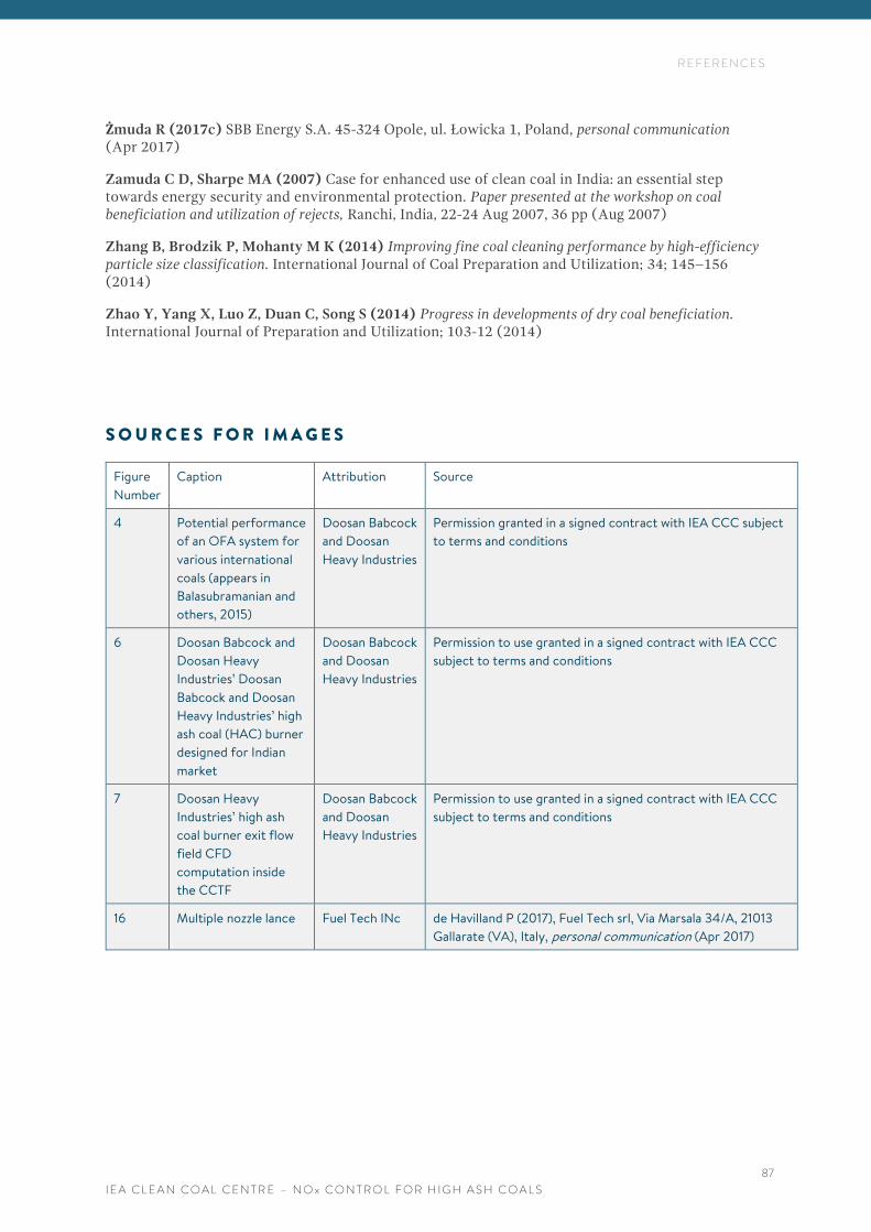
R E F E R E N C E S
I E A C L E A N C O A L C E N T R E – N O x C O N T R O L F O R H I G H A S H C O A L S
87
Żmuda R (2017c) SBB Energy S.A. 45-324 Opole, ul. Łowicka 1, Poland, personal communication (Apr 2017)
Zamuda C D, Sharpe MA (2007) Case for enhanced use of clean coal in India: an essential step towards energy security and environmental protection. Paper presented at the workshop on coal beneficiation and utilization of rejects, Ranchi, India, 22-24 Aug 2007, 36 pp (Aug 2007)
Zhang B, Brodzik P, Mohanty M K (2014) Improving fine coal cleaning performance by high-efficiency particle size classification. International Journal of Coal Preparation and Utilization; 34; 145–156 (2014)
Zhao Y, Yang X, Luo Z, Duan C, Song S (2014) Progress in developments of dry coal beneficiation. International Journal of Preparation and Utilization; 103-12 (2014)
S O U R C E S F O R I M A G E S
Figure
Number
Caption Attribution Source
4 Potential performance
of an OFA system for
various international
coals (appears in
Balasubramanian and
others, 2015)
Doosan Babcock
and Doosan
Heavy Industries
Permission granted in a signed contract with IEA CCC subject
to terms and conditions
6 Doosan Babcock and
Doosan Heavy
Industries’ Doosan
Babcock and Doosan
Heavy Industries’ high
ash coal (HAC) burner
designed for Indian
market
Doosan Babcock
and Doosan
Heavy Industries
Permission to use granted in a signed contract with IEA CCC
subject to terms and conditions
7 Doosan Heavy
Industries’ high ash
coal burner exit flow
field CFD
computation inside
the CCTF
Doosan Babcock
and Doosan
Heavy Industries
Permission to use granted in a signed contract with IEA CCC
subject to terms and conditions
16 Multiple nozzle lance Fuel Tech INc de Havilland P (2017), Fuel Tech srl, Via Marsala 34/A, 21013
Gallarate (VA), Italy, personal communication (Apr 2017)


![NOx Removal Using a Non-thermal Surface Plasma Discharge ... › content › files › pdf › IJPEST_Vol6_No1_13_pp074-080.… · NOx NOx i 100 (3) where [NOx]i and [NOx] are the](https://img.pdfslide.net/doc/110x75/5f1e3ef72e75905a25738ef6/nox-removal-using-a-non-thermal-surface-plasma-discharge-a-content-a-files.jpg)