Embed Size (px)
Citation preview
NPS-52MV8091A
, cUNITED STATESNAVAL POSTGRADUATE SCHOOL
AN INVESTIGATION OF BROADBAND MINIATURE ANTENNAS
by
Andrew Durham Harris
and 00Glen A. Myers
September 1968
This document has been approved for public releaseand sale; its distribution is unlimited.
-- ~u ~- Mi i m __ m i• ± -- 1
I
AN INVESTIGATION OF BROADBAND MINLATURE ANTENNAS
by
Andrew Durham HarrisCaptain, United States Marine Corps
and
Glen A. MyersAssociate Professor of Electrical Engineering
Naval Postgraduate SchoolMonterey, California
September 1968
This task was supported by Naval
Ship Systems Command, Code 6050.
NAVAL POSTGRADUATE SCHOOLMonterey, California
Rear Admiral R. W. McNitt, USN R. F. RinehartSuperintendent Academic Dean
ABSTRACT:
This report considers the application of a negative impedanceconverter to a short monopole antenna. The theory of short antennasand an analysis of the negative impedance converter are presented.The frequency-response characteristics of the negative impedanceconverter are analyzed. The performance of each of various miniatureantenna configurations is compared experimentally with that of a 16foot untuned whip antenna. The nonlinear behavior of the negativeimpedance converter is explored experimentally. Also considered isthe manner in which atmospheric noise level influences the design ofantennas intended to operate in the frequency region below the VHFband.
This task was supported by: Naval Ship Systems Command (Code 6050)
Glen A. Myers Andrew D. HarrisAssociate Professor of Captain, U. S. Marine Corps.Electrical Engineering
Approved by: Released by:
C. H. Rothauge /C. E. MennekenChairman, Departmen of Dean of Research AdministrationElectrical Engineering
NPS-52MV8091A
2
I£TABLE OF CONTENTSI
Page
Chapter 1 Introduction 7 11Chapter 2 Results 11
Chapter 3 Noise Effects 15
Chapter 4 Analysis 17
Chapter 5 Experimental Procedure 26
Chapter 6 Conclusions and Recommendations 29
List of References 31
Appendix A 32
[IJ
LIST OF ILLUSTRATIONS
Figure No. Page
1 Miniature Antenna Representations 8
2 Negative Impedance Converter Representation 9
3 Miniature Antenna and NIC Photographs 10
4 Experimental Arrangement for AntennaComparison Tests 11
5 Gain vs Frequency of Miniature Antenna Relativeto that of a 16 Foot Whip 12
6 Photographs of the NIC Output Voltage Spectrumwhen the Input Consists of Two SimultaneousSinusoidal Signals 14
7 Short Antenna Equivalent Circuit 17
8 Equivalent Circuit of a Short Antenna withCapacitive Top Loading 19
9 Top-Loading Capacitance of a Sphere, Discand Cylinder vs Their Diameters 20
10 Parallel Equivalent Circuit of a Short Antennawith Capacitive Top Loading 21
11 Voltage Inversion Negative Impedance ConverterEquivalent Circuit 22
12 Ideal Voltage Inversion NIC Equivalent Circuit 23
13 Voltage Inversion NIC Circuit Diagram 24
14 Experimental Arrangement for Comparing thePerformance of a Miniature Antenna with thatof a 16 Foot Untuned Whip 26
15 Circuit Used to Determine the NonlinearBehavior of the NIC 27
A-1 Equivalent Circuit of Voltage Inversion NICwith Finite Input Impedance 32
A-2 Equivalent Circuit of Voltage Inversion NICwith Finite Output Impedance 33
TABLE
1 Comparative Gain of Different MiniatureAntenna Configurations 12
5
ACKNOWLEDGEMENT
The authors are pleased to acknowledge the support
of Naval Ship Systems Command (Code 6050) in this study.
6
- 7 -- - - ------
Chapter 1
INTRODUCTION
The electronics field is characteri:ed by progressive
miniaturization of equipment, with integrated circuits providing
the present momentum for this trend. This feature of the elec-
tronics field has rot Penerally been shared by the antenna field.
Traditionally, antenna size has been dictated by the wavelength of
the radiated carrier. Only in the past few years, with the advent
of the space program, has there been any consistent dedicated interest
in size reduction of antennas.
Recently, some work on "small integrated antennas" (SIA) has
been reported [Ref. 1,2]. In general, available engineering data on
the SIA is sparse. Furthermore, the theory of their operation has not
been well presented. As concerns the future development of miniature
antennae, it is perhaps unfortunate at this time that general knowledge
of their status stems from reports in magazines rather than from pub-
lications in professional journals.
This report considers "small" monopole receiving antennas. The
theory of these small antennas and the experimental results obtained
as a part of this study are presented.
A. Backaround Material
A radio antenna may be defined as the structure associated with
the region of transition between a guided wave and a free-space wave,
or vice versa (Ref. 31 A short antenna is one whose uaximm dimension
is much greater than its other two and yet much less than a wavelength
(Ref. 4]. In this report a miniature antenna is defined as a short
antenna.
7
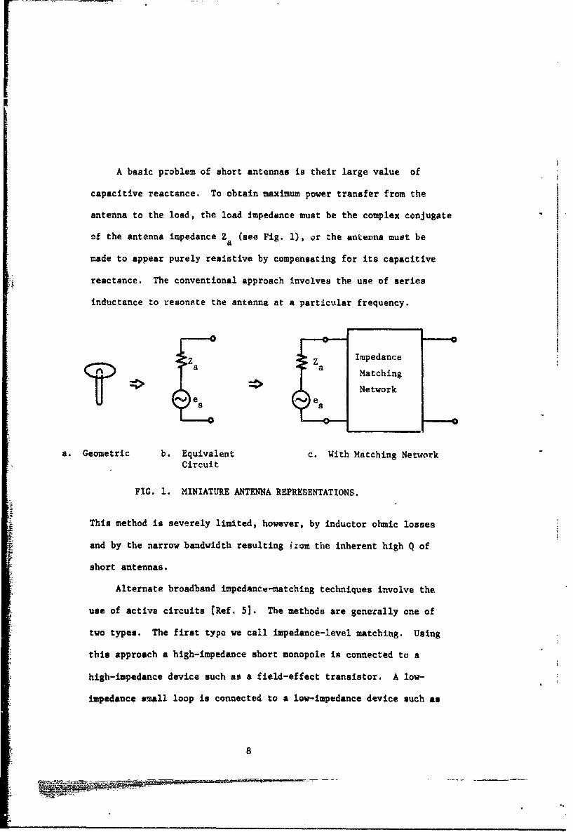
A basic problem of short antennas is their large value of
capacitive reactance. To obtain maximum power transfer from the
antenna to the load, the load impedance must be the complex conjugate
of the antenna impedance Z (see Fig. 1), or the antenna must bea
made to appear purely resistive by compensating for its capacitive
reactance. The conventional approach involves the use of series
inductance to resonate the antenna at a particular frequency.
Z Za Impedancea a Matching
*I Networks es
a. Geometric b. Equivalent c. With Matching NetworkCircuit
FIG. 1. MINIATURE ANTENNA REPRESENTATIONS.
This method is severely limited, however, by inductor ohmic losses
and by the narrow bandwidth resulting from the inherent high Q of
short antennas.
Alternate broadband impedance-matching techniques involve the
use of active circuits [Ref. 5]. The methods are generally one of
two types. The first type we call impedance-level matching. Using
this approach a high-impedance short monopole is connected to a
high-impedance device such as a field-effect transistor. A low-
impedance swall loop is connected to a low-impedance device such as
8
Iii
a common-base transistor amplifier. No effort is made to obtain an
exact conjugate match. Some work on impedance-level matching has been
reported [Ref. 6]. Impedance-level matching is not considered further
in this report.
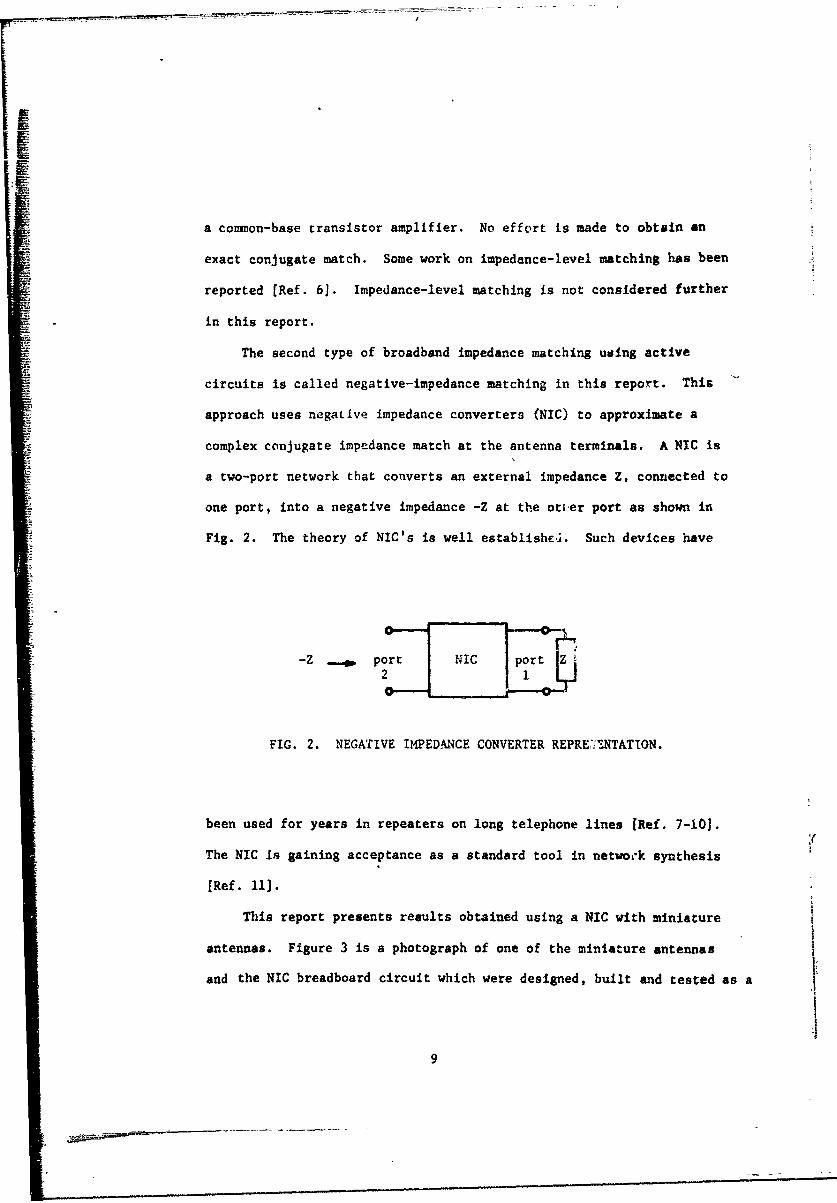
The second type of broadband impedance matching using active
circuits is called negative-impedance matching in this report. This
approach uses negative impedance converters (NIC) to approximate a
complex conjugate impedance match at the antenna terminals. A NIC is
a two-port network that converts an external impedance Z, connected to
one port, into a negative impedance -Z at the otier port as shown in
Fig. 2. The theory of NIC's is well established. Such devices have
-Z _40 port NC port Z
FIG. 2. NEGATIVE IMPEDANCE CONVERTER REPRE7"ý'NTATTON.
been used for years in repeaters on long telephone lines [Ref. 7-10].Y
The NIC is gaining acceptance as a standard tool in netwook synthesis
[Ref. 11].
This report presents results obtained using a NIC with miniature
antennas. Figure 3 is a photograph of one of the miniature antennas
and the NIC breadboard circuit which were designed, built and tested as a
9
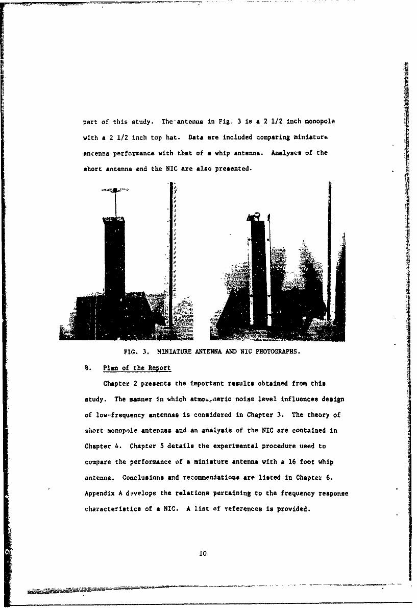
part of this study. The'antenna in Fig. 3 is a 2 1/2 inch monopole
with a 2 1/2 inch top hat. Data are included comparing miniature
ancenna performance with that of a whip antenna. Analyses of the
short antenna and the NIC are also presented.
I-I
FIG. 3. MINIATURE ANTENNA AND NIC PHOTOGRAPHS.
3. Plan of the Report
Chapter 2 presents the important results obtained from this
study. The manner in which atmobeaeric noise level influences design
of low-frequency antennas is considered in Chapter 3. The theory of
short monopole antennas and an analysis of the NIC are contained in
Chapter 4. Chapter 5 details the experimental procedure used to
compare the performance of a miniature antenna with a 16 foot whip
antenna. Conclusions and recommendations are listed in Chapter 6.
Appendix A davelops the relations pertaining to the frequency response
characteristics of a NIC. A list of references is provided.
10
I#
Chapter 2
RESULTS
This section compares the performance of the miniature antenna
with that of a whip antenna. The results of a test to determine non-
linearity of the NIC are also included.
A. Comparative Performance of Miniature Antennas
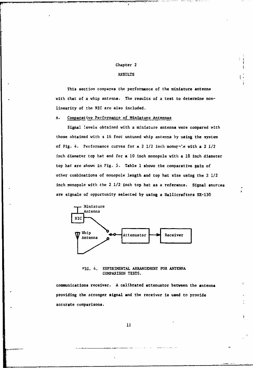
Signal levels obtained with a miniature antenna were compared with
those obtained with a 16 foot untuned whip antenna by using the system
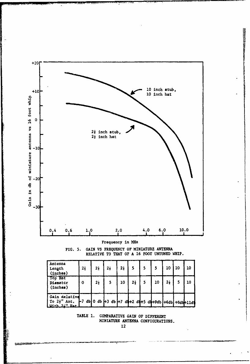
of Fig. 4. Performance curves for a 2 1/2 inch monor-•*.e with a 2 1/2
inch diameter top hat and for a 10 inch monopole with a 10 inch diameter
top hat are shown in Fig. 5. Table 1 shows the conparative gain of
other combinations of monopole length and top hat size using the 2 1/2
inch monopole with the 2 1/2 inch top hat as a reference. Signal sources
are signals of opportunity selected by using a Hallicrafters SX-130
"MiniatureAntenna
NIC
Whip teutrRcirA ntennaAtnu
VIG. 4. EXPERIMENTAL ARRANGEMENT FOR ANTENNACOMPARISON TESTS.
communications receiver. A calibrated attenuator between the antenna
providing the stronger signal and the receiver is used to provide
accurate comparisons.
1-
+20
+10- Aeoo 10 inch stub,IJI+10 inch hat
or.
4J00
%.4
%00
> -10 -
0
4J m
,4
-20
-30-"4,
0.4 0.6 1.0 2.0 4.0 6.0 10.0! I I , I Ii ,I
Frequency in MHz
FIG. 5. GAIN VS FREQUENCY OF MINIATURE ANTENNARELATIVE TO THAT OF A 16 FOOT UNTUNED WHIP.
AntennaLength 2+ 2 f 21 2 5 5 5 0 10 10(inches) IDilameter 0 21 5 10 21 5 10 2½ i 0(inches)
Gain Aelativ. - -
To 2½" Ant. -7 dbl0 db 3 db +7 d 2 d+5 dt9db +6db+d-lidwit'h -71t!Hat- r
TABLE 1. COMPARATIVE GAIN OF DIFFERENTMINIATURE ANTENNA CONFIGURATIONS.
12
Although no noise measurements are made, the noise level is
somewhat higher with the miniature antenna than with the vhip.
This is expected since the NIC used with the miniature antenna
provides a voltage gain of 2. Thus, the noise level due to atmospheric
noise with the m•iniature antenna is at least 6 db higher than with
the whip. The NIC circuit generates some noise, although this noise
should be insignificant compared to atmospheric noise in the region
below 10 MHz. Additional noise considerations ere contained in Chapter
3.
B. Dynamic Rlange Considerations
Very strong signals, in particular the signal from a local broad-
cast station, exceeds the linear signal handling capability of the NIC.
The magnitude of the local broadcast station's received signAl is about
1 volt peak-to-peak at the output of the NIC Spectrum aralysis of the
circuit's output with two simultaneous sinusoidal signals applied yields
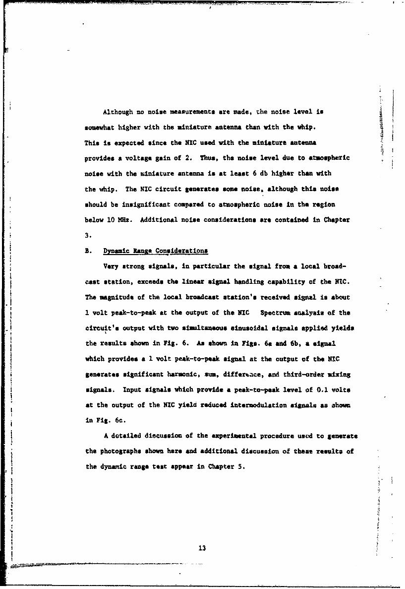
the results shown in Fig. 6. As shown in Figs. 6a and 6b, a signal
which provides a 1 volt peak-to-peak signal at the output of the NIC
generates significant harmonic, sum, differt.ce, and third-order mixing
signals. Input signals which provide a peak-to-peak level of 0.1 volt*
at the output of the NIC yield reduced intermodulation signals as ehown
in Fig. 6c.
A detailed discussion of the experimental procedure used to generate
the photographs shown here and additional discussion of these results of
the dynamic range test appear in Chapter 5.
~1
I"91
__________________________________________________
1 0V4Jw .02
o.07
H 4)
o 100 200 400300 S00
Frequency in kilz.
a. 1 volt peak-to-peak signal amplitudes.
SSame scale as (a)
bi 1 volt-and 0,1 volt peak-to-peak signal amplitudes.
a 0
1. 2.
41 0.70 ~0.3
0Z ~ Same scale as (a)
c. 0.1 volt peak-to-peak signal amplitudes.
FIG. 6. PHOTOGRAPHS OF THE NIC OUTPUTt VOLTAGE SPECTRUMWHEN THE INPUT CONS I TS OF TWO SIMULTANEOUS SINUSOIDALSIGNALS. The input signal frequencies are 200 kilz and230 kHz.
14
Chapter 3 i!
NOISE EFPeCTS
A brief discussion of atwm'spheric noise and its effect on
receiving antenna systems in the frequency region below 10 )s1
is presented in this chapter.
Atmospheric noise level is an important consideration in the
design of receiving systems to operate in the frequency region
below 30 MHz. Curves giving the average field intensity of
atmospheric noise, cosmic noise, and man-made noise versus frequency
are available which show the severe noise level in the frequency
region below 10 M~z [Ref. 12]. In most cases system-performance is
limited by this ambient noise level rather than by antenna perform-
ance. No noise measurements vere made in this study. Thi8 noise-
level limitation is imprtant, however, when specifyin antenna
performance.
In the frequency region below 10 M•z so little sensitivity is
required to receive a signal that is above the atmospheric noise level
that either impedance-level matching or negative-impedance matching
are satisfactory as confirmed by leference 6. In the higher frequency
regions where increased 'ansitivity is 4esirable and where receivers
are device-noise limited instead of natural-aoise limited, the advantages
of negative-impedance matching over impedance-level matching can be
realized.
The results of Chapter 2 show that the performance of the miniature
antenna relative to a whip deteriorates above 10 NH:. The background
[ _I
noise in this frequency region is so high, however, that the
miniature antenna may still be useful to 20 MHz or more.
One might suspect that, due to the broadband characteristic
of the miniature antenna, system noise would be higher than with
a narrowband antenna. It must be remembered, however, that in a
receiving system, the amount of noiae at the output of the system
is typically determined by the bandwidth of the narrowband IF
applifier and not by the bandwidth of the antenna.
16
I!
Chapter 4
ANALYSIS
The theory of short antennas and of voltage inversion negative
impedance converters is presented in this chapter.
A. Short Antenna Theory
We define a short antenna as one whose maximum dimension is much
greater than its other two and yet much less than a wavelength of
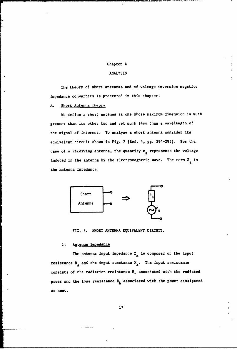
the signal of interest. To analyze a short antenna consider its
equivalent circuit shown in Fig. 7 [Ref. 4, pp. 294-295]. For the
case of a receiving antenna, the quantity e represents the voltage
induced in the antenna by the electromagnetic wave. The term Z isa
the antenna impedance.
Short Za
Antenna__
FIG. 7. SHORT ANTENNA EQUIVALENT CIRCUIT.
1. Antenna Impedance
The antenna input impedance Za is composed of the irput
resistance R and the input reactance X . The input resistancea a
consists of the radiation resistance R associated with the radiatedr
power and the loss resistance Rh associated with the power dissipated
as heat.
17
For a vertical monopole whose length L is much less than
the wavelength X of an electromagnetic wave, we assume a linear
current distribution with zero current at the top and a current
maximum at the base. With such a linear current distribution, the
radiation resistance is given as
Rr 4072 (L/) 2 ohms (1)
r
for a short antenna of length L above a perfect ground [Ref. 4,
p. 309].
The input reactance is capacitive for L less than X/4.
For L much less than X, an approximate equation for antenna capacitance
Ca is [Ref. 4, p. 303]
27re LCa n(L/a)- L << (2)
1whereC C
a uXa
L - height, meters
a - antenna radius, meters
ev - absolute dielectric constant of free space 1 l/(36w)x 10-
farad/meter
For example a monopole with a length L of 2 1/2 inches and a radius a
of 1/8 inch has an antenna capacitance Ca of 0.7 pf.
Capacitive top loading is a technique for increasing the
effective height of a short vertical antenna. As the size of the
capacitive umbrella increases, the effective height increases to a
maximum because of the increase in height of the center of charge;
the effective height then decreases because of the umbrella's shielding
effect on the vertical element [Ref. 13].
18
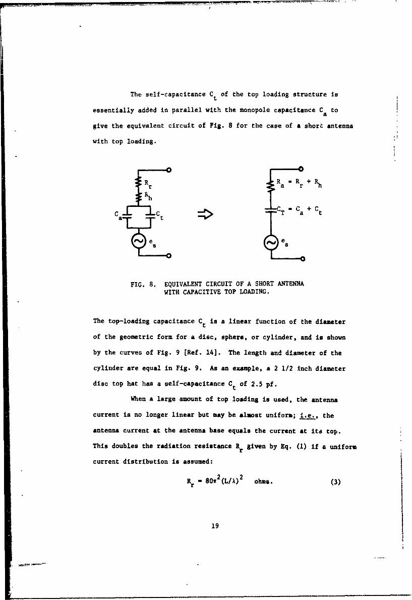
The self-capacitance Ct of the top loading structure is
essentially added in parallel with the monopole capacitance C toa
give the equivalent circuit of Fig. 8 for the case of a short antenna
with top loading.
T a
as j
FIG. 8. EQUIVALENT CIRCUIT OF A SHORT ANTENNAWITH CAPACITIVE TOP LOADING.
The top-loading capacitance Ct is a linear function of the diameter
of the geometric form for a disc, sphere, or cylinder, and is shown
by the curves of Fig. 9 [Ref. 14]. The length and diameter of the
cylinder are equal in Fig. 9. As an example, a 2 1/2 inch diameter
disc top hat has a self-capacitance Ct of 2.5 pf.
When a large amount of top loading is used, the antenna
current is no longer linear but may be almost uniform; i.e., the
antenna current at the antenna base equals the current at its top.
This doubles the radiation resistance R given by Eq. (1) if a uniformr
current distribution is assumed:
R - 80w2 (L/X) 2 ohms. (3)
19
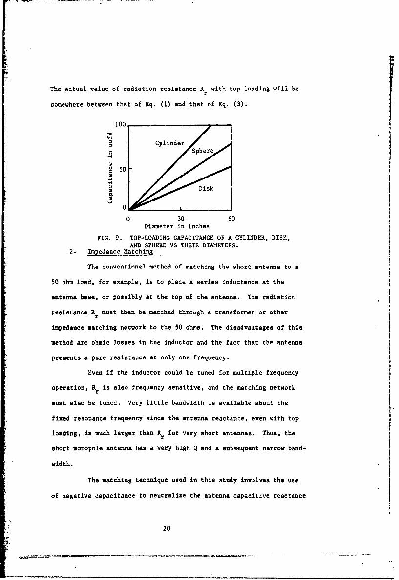
The actual value of radiation resistance R with top loading will ber
somewhere between that of Eq. (1) and that of Eq. (3).
100
CylinderSphere
U 50
944U Disk
0.
0
0 30 60Diameter in inches
FIG. 9. TOP-LOADING CAPACITANCE OF A CYLINDER, DISK,AND SPHERE VS THEIR DIAMETERS.
2. Impedance Matching
The conventional method of matching the short antenna to a
50 ohm load, for example, is to place a series inductance at the
antenna base, or possibly at the top of the antenna. The radiation
resistance R must then be matched through a transformer or otherr
impedance matching network to the 50 ohms. The disadvantages of this
method are ohmic losses in the inductor and the fact that the antenna
presents a pure resistance at only one frequency.
Even if the inductor could be tuned for multiple frequency
operation, Rr is also frequency sensitive, and the matching network
must also be tuned. Very little bandwidth is available about the
fixed resonance frequency since the antenna reactance, even with top
loading, is much larger than R for very short antennas. Thus, ther
short monopole antenna has a very high Q and a subsequent narrow band-
width.
The matching technique used in this study involves the use
of negative capacitance to neutralize the antenna capacitive reactance
20
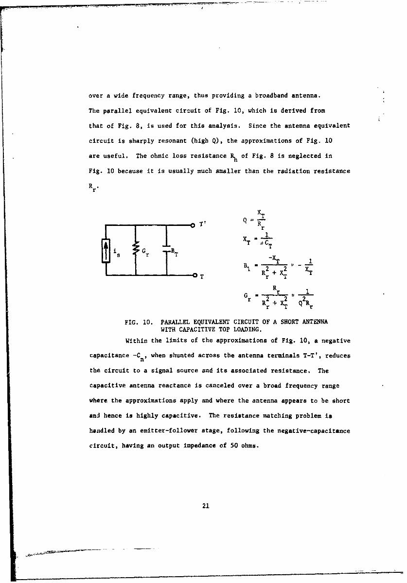
over a wide frequency range, thus providing a broadband antenna.
The parallel equivalent circuit of Fig. 10, which is derived from
that of Fig. 8, is used for this analysis. Since the antenna equivalent
circuit is sharply resonant (high Q), the approximations of Fig. 10
are useful. The ohmic loss resistance Rh of Fig. 8 is neglected in
Fig. 10 because it is usually much smaller than the radiation resistance
R.r
XT
- - T' R
i s G r BTB T-XTBI R2 + 2 XT
i 0 T r -T
R
G Rr 1rr R2+r
FIG. 10. PARALLEL EQUIVALENT CIRCUIT OF A SHORT ANTENNA
WITH CAPACITIVE TOP LOADING.
Within the limits of the approximations of Fig. 10, a negative
capacitance -Cn, when shunted across the antenna terminals T-T', reduces
the circuit to a signal source and its associated resistance. The
capacitive antenna reactance is canceled over a broad frequency range
where the approximations apply and where the antenna appears to be short
ani hence is highly capacitive. The resistance matching problem is
handled by an emitter-follower stage, following the negative-capacitance
circuit, having an output impedance of 50 ohms.
21
B. Theory of Voltage Inversion Negative Impedance Converters
A negative impedance converter (NIC) is defined in Chapter 1.
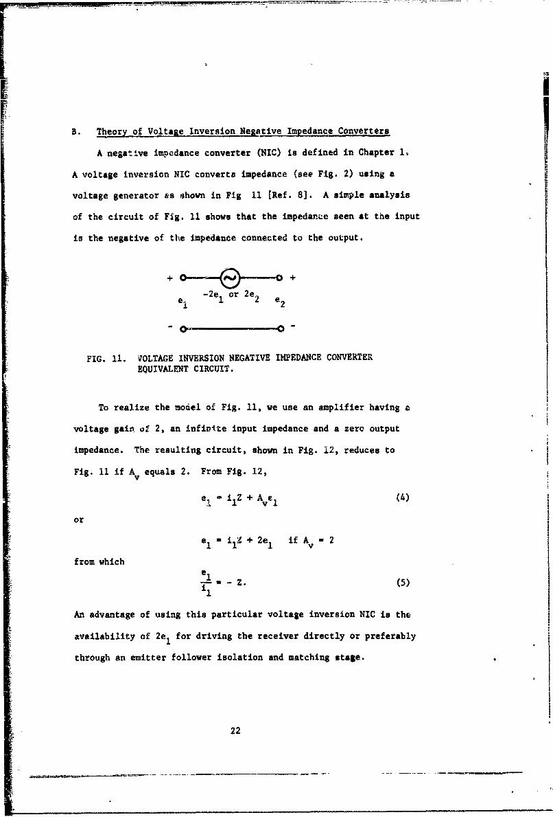
A voltage inversion NIC converts impedance (see Fig. 2) using a
voltage generator &as hown in Fig 11 [Ref. 8]. A simple analysis
of the circuit of Fig. 11 shows that the impedance seen at the input
is the negative of the impedance connected to the output.
+ 0.-&--0 o+
-2e or 2e 2
0- 0-
FIG. 11. VOLTAGE INVERSION NEGATIVE IMPEDANCE CONVERTEREQUIVALENT CIRCUIT.
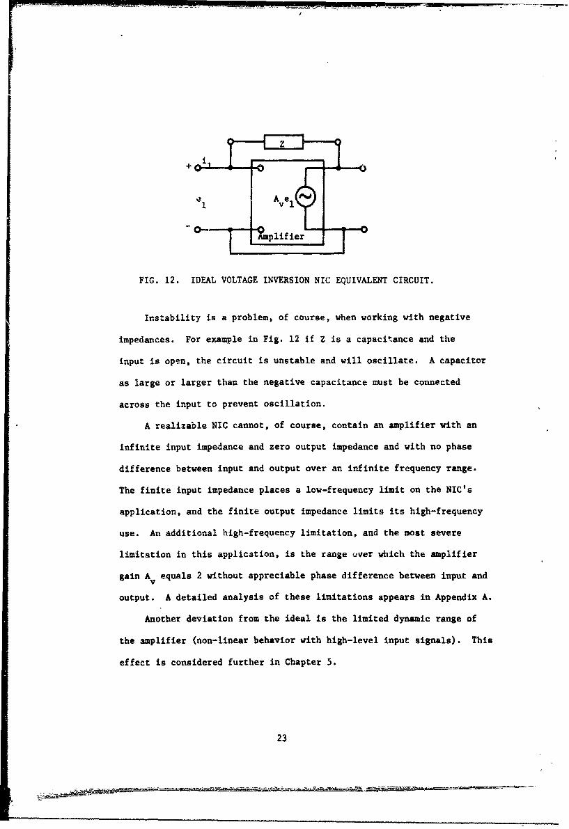
To realize the model of Fig. 11, we use an amplifier having a
voltage gain of 2, an infivite input impedance and a zero output
impedance. The resulting circuit, shown in Fig. 12, reduces to
Fig. 11 if A equals 2. From Fig. 12,v
eC i Z + A e (4)
or
e ,iZ + 2e 1 if A 2
from which
S-Z. (5)£1
An advantage of using this particular voltage inversion NIC is the
availability of 2e 1 for driving the receiver directly or preferably
through an emitter follower isolation and matching stage.
22
+
~,-0
-0- -%plif ier0
FIG. 12. IDEAL VOLTAGE INVERSION NIC EQUIVALENT CIRCUIT.
Instability is a problem, of course, when working with negative
impedances. For example in Fig. 12 if Z is a capacitance and the
input is open, the circuit is unstable and will oscillate. A capacitor
as large or larger than the negative capacitance must be connected
across the input to prevent oscillation.
A realizable NIC cannot, of course, contain an amplifier with an
infinite input impedance and zero output impedance and with no phase
difference between input and output over an infinite frequency range.
The finite input impedance places a low-frequency limit on the NIC's
application, and the finite output impedance limits its high-frequency
use. An additional high-frequency limitation, and the most severe
limitation in this application, is the range over which the amplifier
gain A equals 2 without appreciable phase difference between input andv
output. A detailed analysis of these limitations appears in Appendix A.
Another deviation from the ideal is the limited dynamic range of
the amplifier (non-linear behavior with high-level input signals). This
effect is considered further in Chapter 5.
23
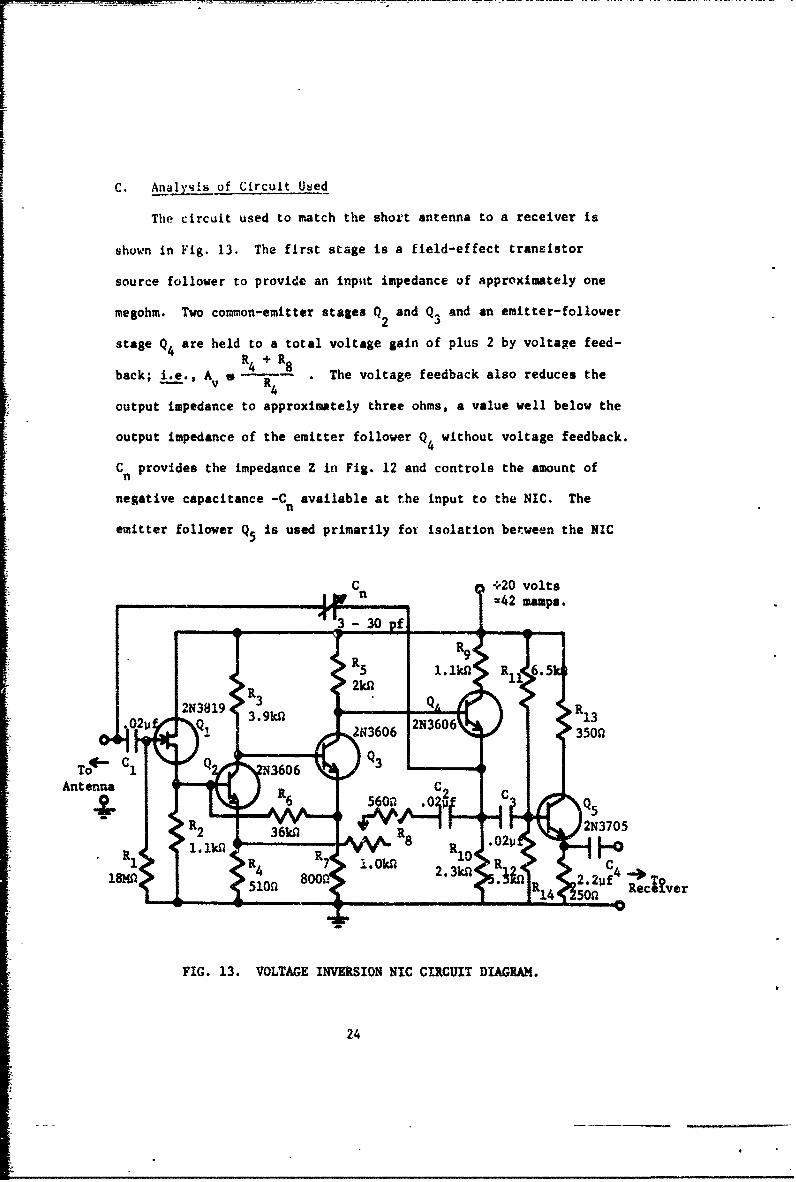
C. Analysis of Circuit Used
The circuit used to match the shor't antenna to a receiver is
shown in Fig. 13. The first stage is a field-effect transistor
source follower to provide an inpitt impedance of approximately one
megohm. Two common-emitter stages Q2 and Q 3 and an emitter-follower
stage Q4 are held to a total voltage gain of plus 2 by voltage feed-
back; i.e., Av s 4 R 8 . The voltage feedback also reduces the
output impedance to approximately three ohms, a value well below the
output impedance of the emitter follower Q without voltage feedback.
C provides the impedance Z in Fig. 12 and controls the amount ofn
negative capacitance -C available at the input to the NIC. Then
emitter follower Q5 is used primarily for isolation between the NIC
IjW C n 20 volts_--42 mamps.
R9R
5 1.lkA R 65
R 2knl1QR2N3819 3 R3
6 2N3606 350n
Q3
Antenna 560 C
?rQ5R 62N3705
R • • 4 R7< -',.Oka .3kaR C 4,
18MA 800 2. 2V f _018510l 80R 1 "4 Rece~ver
FIG. 13. VOLTAGE INVERSION NIC CIRCUIT DIAGRAM.
24
I
[
and the receiver. This stage is not desiped to present a particulair
output ipedamce to any given receiver.
The circuit of Fig. 13 can handle a 4.5 volt peak-to-peek signa
level measured at the output. Larger sitnal. saturate mnd cut off
one or more of the stages. An noted in Chapter 2, siniftcant zon-
limear behavior is observed with one volt peak-to-peak sinal level
at the output.
25
Chapter 5
EXPERIMENTAL PROCEDURE
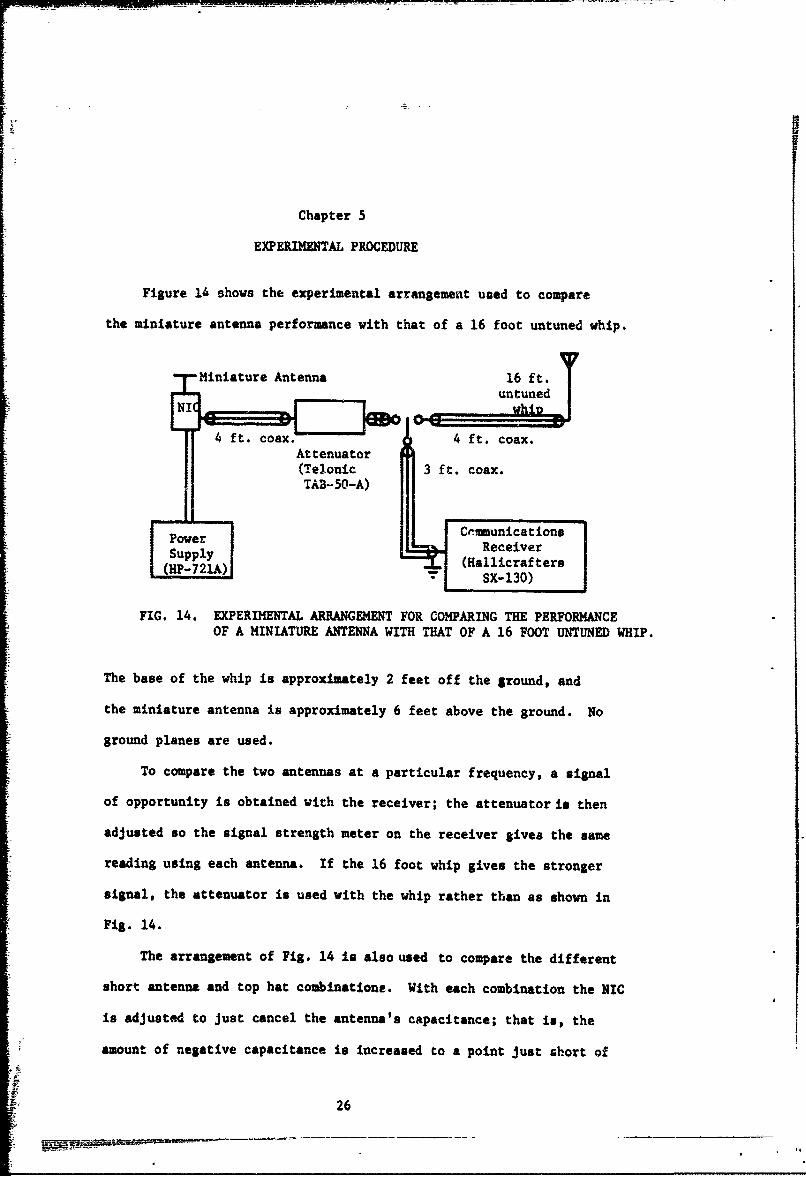
Figure 14 shows the experimental arrangement used to compare
the miniature antenna performance with that of a 16 foot untuned whip.
Miniature Antenna 16 ft.untuned
NI whin
~4 ft. coax.ft. coax. -- - 4 ft. coax.Attenuator
(Telonic 3 ft. coax.TAB-50-A)
Powe C(-unications
SupplyReceiver(HP-21A)(Ha11icrafters
- SX-130)
FIG. 14. EXPERIMENTAL ARRANGEMENT FOR COMPARING THE PERFORMANCEOF A MINIATURE ANTENNA WITH THAT OF A 16 FOOT UNTUNED WHIP.
The base of the whip is approximately 2 feet off the ground, and
the miniature antenna is approximately 6 feet above the ground. No
ground planes are used.
To compare the two antennas at a particular frequency, a signal
of opportunity is obtained with the receiver; the attenuator is then
adjusted so the signal strength meter on the receiver gives the same
reading using each antenna. If the 16 foot whip gives the stronger
signal, the attenuator is used with the whip rather than as shown in
Fig. 14.
The arrangement of Fig. 14 is also used to compare the different
short antenna and top hat combinations. With each combination the NIC
is adjusted to just cancel the antenna's capacitance; that is, the
amount of negative capacitance is increased to a point just short of
26
L
Oscillation. This adjustment also gives the best performance in
each case, as expected. A signal of opport:unity at 1010 kHz is used
for this comparison test.
Initially, the above experiments were attempted at the Naval
Postgraduate School. However, a 1 kilowatt broadcast station about
two miles away made measurements impossible. The broadcast signal
level is approximately one volt peak-to-peak at the NIC output,
exceeding the small-signal linearity limit of the circuit. Harmonics
and mixing signals generated in the NIC by the broadcast station's
signal are troublesome even at frequencies above 10 MHz. To ensure
the absence of very strong signals, a remote residence on the central
California coast about 30 miles from the nearest broadcast station
was used as a site for making measurements.
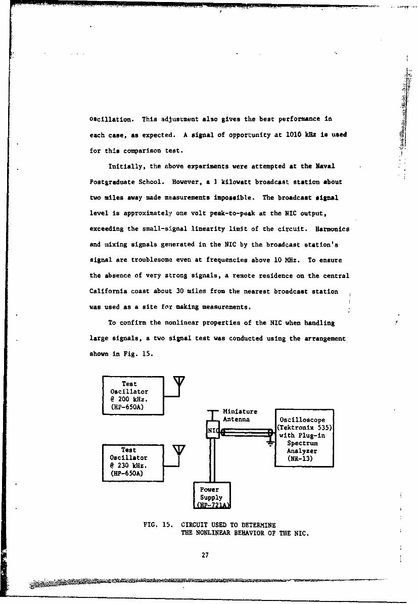
To confirm the nonlinear properties of the NIC when handling
large signals, a two signal test was conducted using the arrangement
shown in Fig. 15.
TestOscillator LY@ 200 kHz.(HP-650A) -- Miniature
Antenna Oscilloscope
NII(Tektronix 535)with Plug-in
-_______ _-- Spectrum
Test AnalyzerOscillator (NR-13)@ 230 kHz.(HP-650A)
FIG. 15. CIRCUIT USED TO DETERMINETHE NONLINEAR BEHAVIOR OF THE NIC.
27
The two antennas shown on the oscillators in Fig. 15 are each
actually 2 foot lengths of wire very near the miniature antenna.
The test oscillators are set to give equal one volt peak-to-peak
signals at the NIC output for one test, unequal signals of one
volt and 0.1 volt peak-to-peak for the second t'st, and equal 0.1
volt peak-to-peak signals for the last test. The results of these
tests are shown as Fig. 6 in Chapter 2.
28
p
Chapter 6
CONCLUSIONS AND RECOKNDATIONS
A. Conclusions
Several conclusions may be drawn from this study. Some of the
more important results are as follows:
1. In the medium-frequency and high-frequency bands, system
performance is usually limited by the atmospheric noise level rather
than antenna performance.
2. A voltage inversion negative impedance converter can be
used to match a short monopole antenna over a broad frequency range
in the medium-frequency region.
3. A 2 1/2 inch monopole with a 2 1/2 inch diameter top hat
and a NIC for matching compares favorably with a 16 foot untuned diip
as a medium-frequency receiving antenna,
4. A limitation of the NIC antenna is significant nonlinear
distortion of large signals due to amplifier nonlinearity in the NIC.
5. Performance of the NIC antenna at high frequencies is limited
by the maximum frequency at which the amplifier in the NIC can provide
a voltage gain of 2 with negligible phase shift.
B. Recommendations
This study indicates some areas where further investigation is
warranted.
1. The high-frequency performance of the NIC could possibly be
extended by judicious selection of transivtors and additional engineering
effort to minimize the phase shift of the NIC amplifier at higher fre-
quencies.
29
2. The current inversion negative impedance converter (rather
than the voltage inversion NIC) could possibly be applied to miniature
antennas, with improved high-frequency performance resulting.
3. The application of negative impedance converters to miniature
tranmitting antennas is worthy of consideration.
4. Sensitivity of the miniature antenna NIC configuration should
be measured.
30
LIST OF REFERENCES
1. "And Now the Mini-Antenna," Time, Vol. 89, No. 20, May 19, 1967,p. 124.
2. "Reception is Loud and Cool for Subminiature Antennas," Electronics,Vol. 40, No. 12, June 12, 1967, pp. 145-148.
3. J. D. Kraus, Antennas, McGraw-Hill Book Company, Inc., New York,1950, p. 1.
4. S. A. Schelkunoff and H. T. Friis, Antennas_,Theory and Practice,John Wiley and Sons, Inc., New York, 1952.
5. S. Laxpati and R. Mittra, "Antenna Impedance Matching by Meansof Active Networks," Elec. Engrg. Research Lab., Engrg. ExperimentStation, University of Illinois, Urbana, Antenna Lab. Tech. Rept.64, November 1962.
6. "Philco-Ford Broadband Antenna System Capabilities," Report No.WDL-B402, Philco-Ford Corp., WDL Division, Palo Alto.
7. J. G. Linvill, "Transistor Negative Impedance Converters," Proc.IRE, Vol. 41, No. 6, June 1953, pp. 725-729.
8. A. I. Larky, "Negative-Impedance Converters," IRE Trans. onCircuit Theory, Vol. CT-4, No. 3, September 1957, pp. 124-131.
9. J. L. Merrill, "Theory of the Negative--Impedance Conrerter,"Bell Sys. Tech. J., Vol. 30, No. 1, January 1951, pp. 88-109.
10. T. Yanagisawa, "RC Active Networks Using Current Inversion TypeNegative Impedance Converters," IRE Trans. on Circuit Theory,Vol. CT-4, No. 3, September 1957, pp. 140-144.
11. K. L. Su, Active Network Synthesis, McGraw-Hill Book Company,Inc., New York, 1965, pp. 42-48.
12. Reference Data for Radio Engineers, International Telephone andTelegraph Corp., American Book-Stratford Press, Inc., New York,1956, p. 763.
13. H. Jasik, Antenna Ensineering Handbook, McGraw-Hill Book Company,Inc., New York, 1961, p. 19-5.
14. The ARRL Antenna Book, The American Radio Relay League, Inc.,Newington, Conn., 1960, p. 63.
15. Louis de Pian and Arnold Meltzer, "Active Filters: Part 3Negative-Impedance Converters," Electronics, Vol. 41, No. 18,September 2, 1968, pp. 82-93.
31
Appendix A
ANALYSIS OF FREQUENCY LIMITATIONS
OF THE VOLTAGE INVERSION NIC
This Appendix analyzes the frequency response of a voltage
inversion NIC having finite input impedance, nonzero output
impedance, and a nonzero amplifier phase vs frequency characteristic.
To simplify the analysis problem, with a slight sacrifice in accuracy,
each deviation from the ideal amplifier with a voltage gain of 2 is
considered separately.
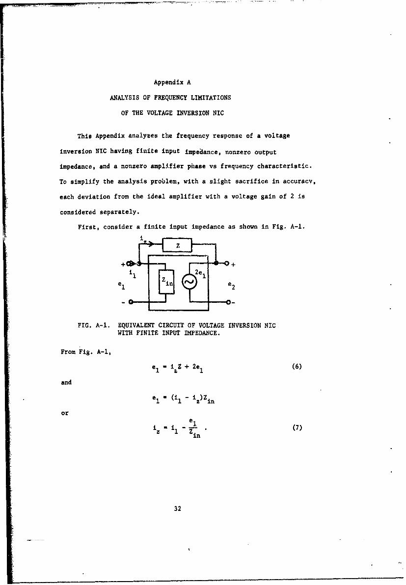
First, consider a finite input impedance as shown in Fig. A-1.
i
FIG. A-I. EQUIVALENT CIRCUIT OF VOLTAGE INVERSION NICWITH FINITE INPUT IMPEDANCE.
From Fig. A-I,e- i Z + 2e (6)
and
e- (i1 - iz )Z in
ore1
i i e -(7)Zin
32
Substituting Eq. (7) into Eq. (6) yieldselZ
el - iZ - Z + 2e1
1 z I
Zin
which after rearranging gives
eI -i
The desired negative impedance is
-z "(8)
For the case of Z a capacitive reactance and Zin a pure resistance,
Eq. (8) becomes
1 1 1 1 1> 1(9i JWC 1 R -- jWC --- ' Z, Rin wC
J-wCRij
Thus, a finite value of NIC input resistance Rin affects the low-
frequency performance of the NIC to the extent shown in Eq. (9).
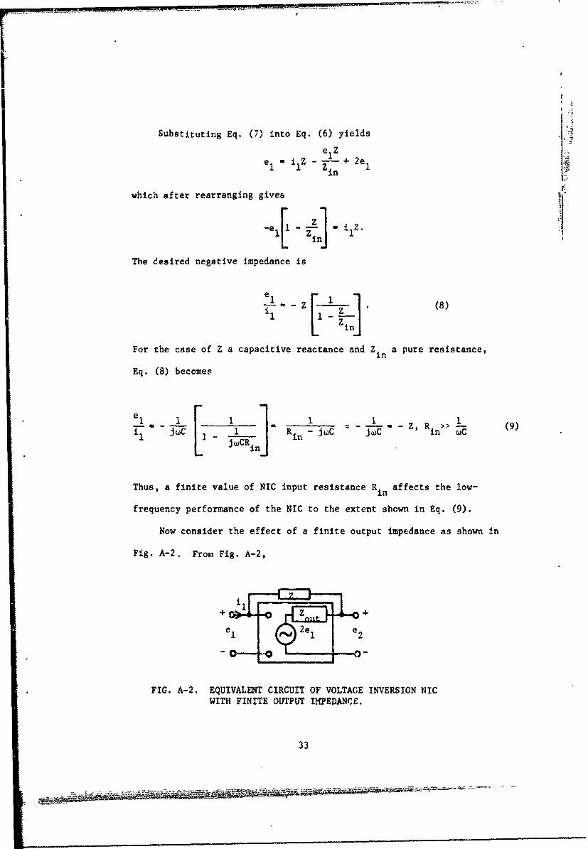
Now consider the effect of a finite output impedance as shown in
Fig. A-2. From Fig. A-2,
+ +
FIG. A-2. EQUIVALENT CIRCUIT OF VOLTAG;E INVERSION NICWITH FINITE OUTPUT IMPEDANCE.
33
•1 i(Z + z out) + 2e V
Then,
For the case of Z a capacitive reactance and Zout a pure resistance,
Eq. (10) becomes
1 --- (1 1+ j CR Z when 1
Thus, a finite value of NIC output resistance Rou affects the high-
frequency performance of the NIC to the extent shown in Eq. (11).
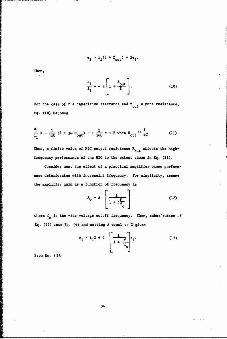
Consider next the effect of a practical amplifier whose perform-
ance deteriorates with increasing frequency. For simplicity, assume
the amplifier gain as a function of frequency is
AA (12)
where fc is the -3db voltage cutoff frequency. Then, subst:tution uf
Eq. (12) into Eq. (4) and setting A equal to 2 gives
1iZ + 2 e (13)
From Eq. (13)
34
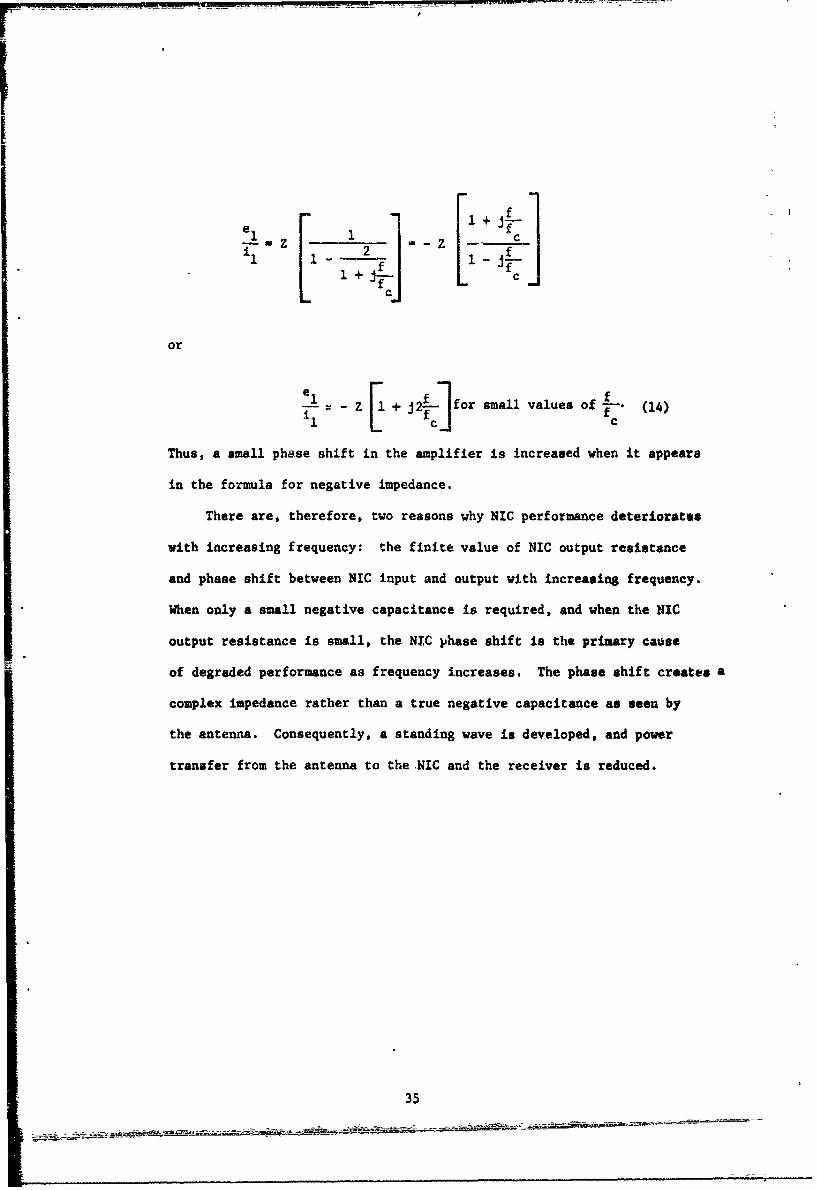
e z 2 Z f cI-- -z = -z-- ~
or
[I c- for small values of f 4 - )__ -Z + J (14)
Thus, a small phase shift in the amplifier is increased when it appears
in the formula for negative impedance.
There are, therefore, two reasons why NIC performance deteriorates
with increasing frequency: the finite value of NIC output resistance
and phase shift between NIC input and output with increasing frequency.
When only a small negative capacitance is required, and when the NIC
output resistance is small, the NIC phase shift is the primary cause
of degraded performance as frequency increases. The phase shift creates a
complex impedance rather than a true negative capacitance as seen by
the antenna. Consequently, a standing wave is developed, and power
transfer from the antenna to the .NIC and the receiver is reduced.
35
Unclassafied
DOCUMENT CONTROL DATA• R & D-se-• itr -l.o . Isticatiun of tithe, hodt of •ihstnct •cnd .mde.xinj mannottinim nju.v bc nluer•d when the overall report is l*ailied)
I OH ,NA TIN,(. AC TIVI T, (Corpor.te o,) 2a.. REPORT SECURITY CLASS1 FICATIONO
Naval Postgraduate School UnclassifiedMonterey, California 93940 2b. GAoUP
,l Rf PO0 T TITLE
An Investigation of Broadband Miniature Antennas
4 O•ESCRIPTIVE NOTES (Typo of report and.lheclusave dae&l)
Technical Report - September 1968S AU THORISi (First name, middle initial, last name)
Andrew D. Harris Captain, U. S. Marine CorpsGlen A. Myers Assoc. Prof., Naval Postgraduate School
I REPORT OATE 7It. TOTAL NO OF PAGES [lb. NO. O7" RSr
September 1958 36 15A. CONTRACT OR GRANT NO. 5.. ORIGINATOR'S REPORT NUIArllef)I
6. PROJECT No. NPS-52MV8091A
C. 9b. OTHER REPORT NOIS) (Any othernus•smbs 1Esety be h l aaaedthis report)
a.
10. OISTRIOUTION STATEMENT
This document has been approved for public release and sale; its distributionis unlimited.
SI. SuPPLEMIENTARY NOTES 152. SPONSORING MILITARY ACTIVITYJ Naval Ship Systems CommandCode 6050
13. ASrTRACT
Th.. report considers the application of a negative impedance converter to a
short monopole antenna. The theory of short antennas and an analysis of the negative
impedance converter are presented. The frequency-response characteristics of the
negative impedance converter are analyzed. The performance of each of various
miniature antenna configurations is compared experimentally with that of a 16 foot
untuned whip antenna. The nonlinear behavior of the negative impedance converter
is explored experimentally. Also considered is the manner in which atmospheric noise
level influences the design of antennas intended to operate in the frequency region
below the VHF band.,
DD FOMPAGE 1)D D e-O-eM 1473 ( 37 Unclassified
S/N 0101-807-6811 Secu'ri , Classification UA-31406
Unclassifieds* vuritt C(•'visfi,'ation
t4K * ROS LINK A LINK 0 j LINK
ROL . WT ROLF VVT r4OLE WT
AntennaMonopole antennaReceiving antennaMiniature antennaSubminiature antennaSmall antennaImpedance converterNegative-impedance converterShort antennaBroadband antenna
DD ,m:•.1473 (BACK) 38 UnclassifiedS/• ;I o - o•. ?Security C lassification A- -,1400o