Embed Size (px)
Citation preview
NW000-S0038 UNCONTROLLED IF PRINTED Page 1 of 23
Network Standard
NETWORK
Document No Amendment No Approved By Approval Date Review Date
: : : : :
NW000-S0038 1 A/Head of AEP & S 12/07/2019 12/07/2022
(Supersedes Network Standard (NETWORK) Document No. NW000-S0038 Amdt No.0)
NW000-S0038 NS253 TERMINATION OF WIRING IN SUBSTATION PROTECTION AND CONTROL EQUIPMENT
NS253 Termination of wiring in substation protection and control equipment Amendment No 1
NW000-S0038 UNCONTROLLED IF PRINTED Page 2 of 23
ISSUE
For issue to all Ausgrid and Accredited Service Providers’ staff involved with the termination of wiring in substation protection and control equipment, and is for reference by field, technical and engineering staff.
Ausgrid maintains a copy of this and other Network Standards together with updates and amendments on www.ausgrid.com.au.
Where this standard is issued as a controlled document replacing an earlier edition, remove and destroy the superseded document
DISCLAIMER
As Ausgrid’s standards are subject to ongoing review, the information contained in this document may be amended by Ausgrid at any time. It is possible that conflict may exist between standard documents. In this event, the most recent standard shall prevail.
This document has been developed using information available from field and other sources and is suitable for most situations encountered in Ausgrid. Particular conditions, projects or localities may require special or different practices. It is the responsibility of the local manager, supervisor, assured quality contractor and the individuals involved to make sure that a safe system of work is employed and that statutory requirements are met.
Ausgrid disclaims any and all liability to any person or persons for any procedure, process or any other thing done or not done, as a result of this Standard.
All design work, and the associated supply of materials and equipment, must be undertaken in accordance with and consideration of relevant legislative and regulatory requirements, latest revision of Ausgrid’s Network Standards and specifications and Australian Standards. Designs submitted shall be declared as fit for purpose. Where the designer wishes to include a variation to a network standard or an alternative material or equipment to that currently approved the designer must obtain authorisation from the Network Standard owner before incorporating a variation to a Network Standard in a design.
External designers including those authorised as Accredited Service Providers will seek approval through the approved process as outlined in NS181 Approval of Materials and Equipment and Network Standard Variations. Seeking approval will ensure Network Standards are appropriately updated and that a consistent interpretation of the legislative framework is employed.
Notes: 1. Compliance with this Network Standard does not automatically satisfy the requirements of a Designer Safety Report. The designer must comply with the provisions of the Workplace Health and Safety Regulation 2017 (NSW - Part 6.2 Duties of designer of structure and person who commissions construction work) which requires the designer to provide a written safety report to the person who commissioned the design. This report must be provided to Ausgrid in all instances, including where the design was commissioned by or on behalf of a person who proposes to connect premises to Ausgrid’s network, and will form part of the Designer Safety Report which must also be presented to Ausgrid. Further information is provided in Network Standard (NS) 212 Integrated Support Requirements for Ausgrid Network Assets.
2. Where the procedural requirements of this document conflict with contestable project procedures, the contestable project procedures shall take precedent for the whole project or part thereof which is classified as contestable. Any external contact with Ausgrid for contestable works projects is to be made via the Ausgrid officer responsible for facilitating the contestable project. The Contestable Ausgrid officer will liaise with Ausgrid internal departments and specialists as necessary to fulfil the requirements of this standard. All other technical aspects of this document which are not procedural in nature shall apply to contestable works projects.
INTERPRETATION
In the event that any user of this Standard considers that any of its provisions is uncertain, ambiguous or otherwise in need of interpretation, the user should request Ausgrid to clarify the provision. Ausgrid’s interpretation shall then apply as though it was included in the Standard, and is final and binding. No correspondence will be entered into with any person disputing the meaning of the provision published in the Standard or the accuracy of Ausgrid’s interpretation.
KEYPOINTS
This standard has a summary of content labelled “KEYPOINTS FOR THIS STANDARD”. The inclusion or omission of items in this summary does not signify any specific importance or criticality to the items described. It is meant to simply provide the reader with a quick assessment of some of the major issues addressed by the standard. To fully appreciate the content and the requirements of the standard it must be read in its entirety.
AMENDMENTS TO THIS STANDARD
Where there are changes to this standard from the previously approved version, any previous shading is removed and the newly affected paragraphs are shaded with a grey background. Where the document changes exceed 25% of the document content, any grey background in the document is to be removed and the following words should be shown below the title block on the right hand side of the page in bold and italic, for example, Supersedes – document details (for example, “Supersedes Document Type (Category) Document No. Amendment No.”).
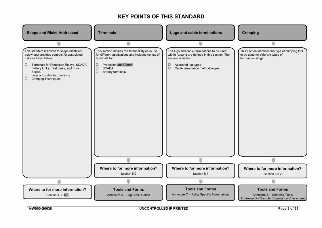
KEY POINTS OF THIS STANDARD
NW000-S0038 UNCONTROLLED IF PRINTED Page 3 of 23
Terminals Lugs and cable terminations Crimping Scope and Risks Addressed
Tools and Forms Annexure C – Relay Specific Terminations
Tools and Forms Annexure B – Crimping Tools
Annexure D – Sample Compliance Checksheet
This standard is limited to scope identified below and provides controls for associated risks as listed below:
Terminals for Protection Relays, SCADA, Battery Links, Test Links, and Fuse Bases.
Lugs and cable terminations. Crimping Techniques
Where to for more information? Section 1, 2, 5.1
This section defines the terminal styles in use for different applications and includes review of terminals for:
Protection and Control SCADA Battery terminals
The lugs and cable terminations to be used within Ausgrid are defined in this section. The section includes:
Approved lug types Cable termination methodologies
This section identifies the type of crimping tool to be used for different types of terminations/lugs.
Tools and Forms Annexure A – Lug Stock Codes
Where to for more information? Section 5.2
Where to for more information? Section 5.3
Where to for more information? Section 5.3.2
NS253 Termination of wiring in substation protection and control equipment Amendment No 1
NW000-S0038 UNCONTROLLED IF PRINTED Page 4 of 23
Network Standard NS253
Termination of Wiring in Substations Protection and Control Equipment
Contents
1.0 PURPOSE ............................................................................................................................................. 5
2.0 SCOPE .................................................................................................................................................. 5
3.0 REFERENCES ...................................................................................................................................... 5 3.1 Ausgrid documents .................................................................................................................... 5 3.2 Other standards and documents ................................................................................................ 5 3.3 Acts and regulations ................................................................................................................... 5
4.0 DEFINITIONS ........................................................................................................................................ 6
5.0 TERMINATION OF WIRING .................................................................................................................. 7 5.1 General....................................................................................................................................... 7 5.2 Terminals ................................................................................................................................... 7
5.2.1 Protection and control terminals ..................................................................................... 7 5.2.2 SCADA terminals ........................................................................................................... 8 5.2.3 Moulded links ................................................................................................................. 8 5.2.4 Red spot back stud connected fuse holder .................................................................. 10
5.3 Lugs and cable terminations .................................................................................................... 11 5.3.1 Termination types ......................................................................................................... 11 5.3.2 Cable termination crimping .......................................................................................... 12 5.3.3 Cable sheath terminations ........................................................................................... 13
5.4 Exclusions ................................................................................................................................ 13 5.4.1 Splicing joining ............................................................................................................. 13 5.4.2 Terminals in OEM / pre-built packages ........................................................................ 13
6.0 RECORDKEEPING ............................................................................................................................. 14
7.0 AUTHORITIES AND RESPONSIBILITIES .......................................................................................... 14
8.0 DOCUMENT CONTROL...................................................................................................................... 14
ANNEXURE A - LUG STOCK CODES ........................................................................................................... 15
ANNEXURE B - CRIMPING TOOLS ............................................................................................................... 16
ANNEXURE C - RELAY SPECIFIC TERMINATIONS .................................................................................... 17 C1 Table of relay terminals .................................................................................................................. 17 C2 Multiple lugs on one terminal ......................................................................................................... 20 C3 Unacceptable terminations ............................................................................................................. 21
ANNEXURE D – SAMPLE COMPLIANCE CHECKLIST ................................................................................ 22
NS253 Termination of wiring in substation protection and control equipment Amendment No 1
NW000-S0038 UNCONTROLLED IF PRINTED Page 5 of 23
1.0 PURPOSE This standard sets out the minimum requirements for control and protection terminals, lugs and cable termination methods used in substation wiring.
2.0 SCOPE This standard applies to the termination of substation control and protection stranded wiring with a cross sectional area of 0.05 mm2 to 16 mm2.
The following is included: • New work. • Protection and control wiring lugs, terminals, links, fuse holders, and the associated crimping
tools to be used.
The following is not included: • The wiring in equipment supplied to Ausgrid covered by the original equipment manufacturer
in which the method of wiring has been approved as part of the procurement contract, e.g. pre-wired switchgear panels and tap-changer control boxes mounted on transformers.
• Metering terminations. • Terminations to AC Boards.
3.0 REFERENCES All work covered in this document shall conform to all relevant Legislation, Standards, Codes of Practice and Network Standards. Current Network Standards are available on Ausgrid’s Internet site at www.ausgrid.com.au.
3.1 Ausgrid documents • Company Form (Governance) - Network Document Endorsement and Approval • Company Procedure (Governance) - Network Document Endorsement and Approval • Company Procedure (Network) - Production / Review of Network Standards • Electrical Safety Rules • Electricity Network Safety Management System Manual • NS181 Approval of Materials and Equipment and Network Standard Variations • NS203 Telecommunications: Master Policy Document • NS212 Integrated Support Requirements for Ausgrid Network Assets • NS250 Secondary Systems – Requirements for CT, VT and tripping circuits • NS251 Requirements for cables between panels • NS252 Secondary Systems – Requirements for wiring within panels • NS261 Requirement for Design Compliance Framework for Network Standards
3.2 Other standards and documents • AS 4437 Solderless crimped connections – General requirements, test methods and
practical guidance • AS 4325.1 Compression and Mechanical Connectors for Power Cables With Copper or
Aluminium Conductors • ENA Doc 001-2008 National Electricity Network Safety Code
3.3 Acts and regulations • Electricity Supply (General) Regulation 2014 (NSW) • Electricity Supply (Safety and Network Management) Regulation 2014 • Work Health and Safety Act 2011 and Regulation 2011
NS253 Termination of wiring in substation protection and control equipment Amendment No 1
NW000-S0038 UNCONTROLLED IF PRINTED Page 6 of 23
4.0 DEFINITIONS Accredited Service Provider (ASP)
An individual or entity accredited by the NSW Department of Planning and Environment, Energy, Water and Portfolio Strategy Division, in accordance with the Electricity Supply (Safety and Network Management) Regulation 2014 (NSW).
Approved Materials List (AML)
A dynamic list of materials and equipment approved (at that point in time) for installation on Ausgrid’s network, a supporting document to NS181 Approval of Materials and Equipment and Network Standard Variations.
Business Management System (BMS)
An Ausgrid internal integrated policy and procedure framework that contains the approved version of documents.
Crimp An electrical connector that is compressed onto a conductor.
Document control
Ausgrid employees who work with printed copies of document must check the BMS regularly to monitor version control. Documents are considered “UNCONTROLLED IF PRINTED”, as indicated in the footer.
Link A pair of terminals in-line with a wire connection that serves as a point for the electrical separation of a circuit, usually consisting of a screw-tightened sliding connector between the terminals.
Lug A conducting fitting that can be connected to an electrical conductor.
Network Standard
A document, including Network Planning Standards, that describes the Company's minimum requirements for planning, design, construction, maintenance, technical specification, environmental, property and metering activities on the distribution and transmission network. These documents are stored in the Network Category of the BMS repository.
Panel The cubicle in/onto which protection and control equipment is mounted. Panel may also refer specifically to the front sheet metal to which relays are mounted and then fixed to the rest of the cubicle.
Review date The review date displayed in the header of the document is the future date for review of a document. The default period is three years from the date of approval however a review may be mandated at any time where a need is identified. Potential needs for a review include changes in legislation, organisational changes, restructures, occurrence of an incident or changes in technology or work practice and/or identification of efficiency improvements.
Terminal A point of connection in an electric circuit for one or more wire ends or connectors.

NS253 Termination of wiring in substation protection and control equipment Amendment No 1
NW000-S0038 UNCONTROLLED IF PRINTED Page 7 of 23
5.0 TERMINATION OF WIRING 5.1 General
A basic summary of the requirements in this document is as follows: • All protection and control wiring terminations must meet the requirements of AS 4437 or AS
4325.1. • Compression type solderless lugs shall be used at the terminations of all stranded wires. • The lugs shall be manufactured from high conductivity copper. • The correct size lug shall be used to suit the wire size. • Only lugs with a pre-insulated crimp barrel shall be used to prevent direct or accidental
contact with adjacent terminations. • The un-lugged termination of bare wire strands into terminals is not permitted. • All lugs shall be crimped with the correct compression crimping tool recommended by the lug
manufacturer. • Under no circumstances shall lugs be bent, filed, cut or modified in any way to fit a
termination. The lug’s insulation shall not be removed.
5.2 Terminals 5.2.1 Protection and control terminals
Terminals for protection and control connections are required to meet the performance criteria outlined in Table 1 (see drawing 50993 for further details).
Table 1 – Performance Criteria
Parameter Preferred Alternative (retrofits and to match existing installations)
Connection type M5 stud M6 stud
Current carrying capacity, continuous
30 A 30 A
Insulation voltage withstand 500 V 500 V
Temperature index of insulating material (minimum)
120 °C 120 °C
Stud material Passivated stainless steel (18/8 family)
Passivated stainless steel (18/8 family)
Nuts and washers Passivated stainless steel (18/8 family)
Passivated stainless steel (18/8 family)
Links, link plates Passivated stainless steel (18/8 family)
Passivated stainless steel (18/8 family)
Note: 18/8 is also known as 300 series (type 304, 305, 316) and consists of 18% chromium & 8% nickel.
To reduce the propensity for galling nuts should only be driven at low speed by hand. The threads should be clean and smooth and the correct torque applied.
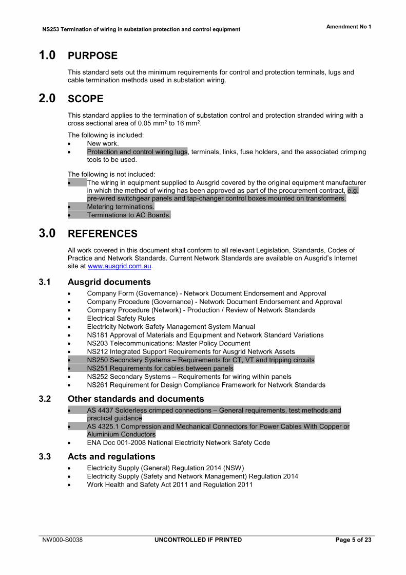
5.2.1.1 General protection terminals (not including wiring in OEM supplied packages) Terminals for protection connections are required to accept ring terminals using a dual bolt, nut and bolt connection terminal block with M5 studs (e.g. Utilux H3820 terminals as per Figure 1). Slotted screw terminals are not to be used due to the risk of either slot damage or subsequent under-torquing due to a damaged slot.
NS253 Termination of wiring in substation protection and control equipment Amendment No 1
NW000-S0038 UNCONTROLLED IF PRINTED Page 8 of 23
Figure 1: Utilux H3820 Dual Stud Terminals
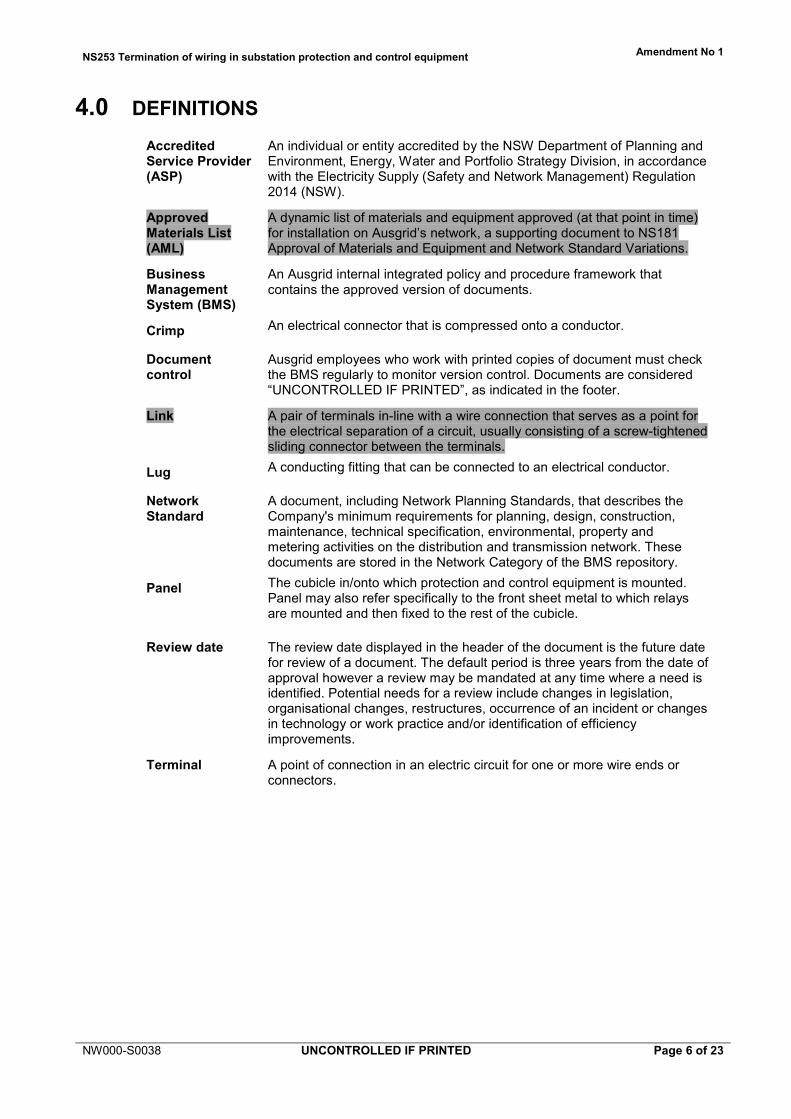
5.2.2 SCADA terminals SCADA wiring is generally a smaller cross sectional area than control and protection cabling and hence dual post terminals are not necessary for use as terminals for SCADA. Terminal blocks with DIN rail mountings (e.g. Weidmuller Din Rail Mount Terminals as per Figure 2) are generally used for termination of SCADA and associated control wiring.
Figure 2: Example Weidmuller SAKR Terminals
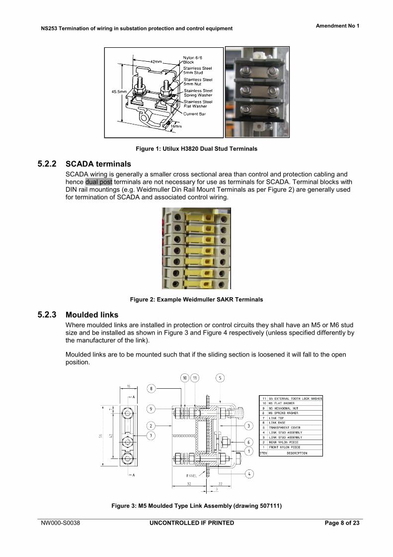
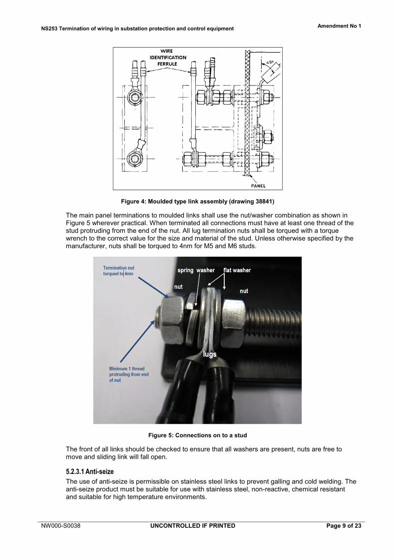
5.2.3 Moulded links Where moulded links are installed in protection or control circuits they shall have an M5 or M6 stud size and be installed as shown in Figure 3 and Figure 4 respectively (unless specified differently by the manufacturer of the link).
Moulded links are to be mounted such that if the sliding section is loosened it will fall to the open position.
Figure 3: M5 Moulded Type Link Assembly (drawing 507111)
NS253 Termination of wiring in substation protection and control equipment Amendment No 1
NW000-S0038 UNCONTROLLED IF PRINTED Page 9 of 23
Figure 4: Moulded type link assembly (drawing 38841)
The main panel terminations to moulded links shall use the nut/washer combination as shown in Figure 5 wherever practical. When terminated all connections must have at least one thread of the stud protruding from the end of the nut. All lug termination nuts shall be torqued with a torque wrench to the correct value for the size and material of the stud. Unless otherwise specified by the manufacturer, nuts shall be torqued to 4nm for M5 and M6 studs.
Figure 5: Connections on to a stud
The front of all links should be checked to ensure that all washers are present, nuts are free to move and sliding link will fall open.
5.2.3.1 Anti-seize The use of anti-seize is permissible on stainless steel links to prevent galling and cold welding. The anti-seize product must be suitable for use with stainless steel, non-reactive, chemical resistant and suitable for high temperature environments.
NS253 Termination of wiring in substation protection and control equipment Amendment No 1
NW000-S0038 UNCONTROLLED IF PRINTED Page 10 of 23
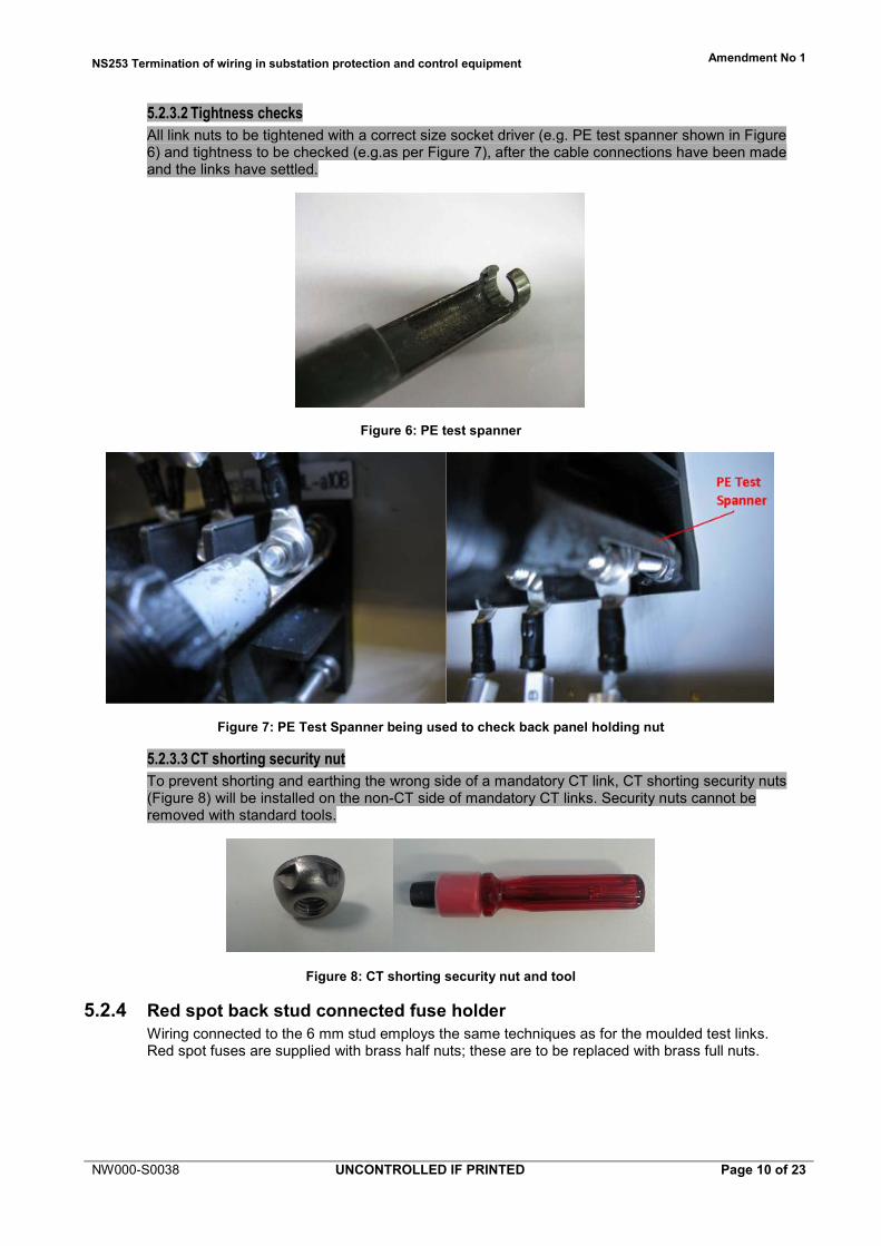
5.2.3.2 Tightness checks All link nuts to be tightened with a correct size socket driver (e.g. PE test spanner shown in Figure 6) and tightness to be checked (e.g.as per Figure 7), after the cable connections have been made and the links have settled.
Figure 6: PE test spanner
Figure 7: PE Test Spanner being used to check back panel holding nut
5.2.3.3 CT shorting security nut To prevent shorting and earthing the wrong side of a mandatory CT link, CT shorting security nuts (Figure 8) will be installed on the non-CT side of mandatory CT links. Security nuts cannot be removed with standard tools.
Figure 8: CT shorting security nut and tool
5.2.4 Red spot back stud connected fuse holder Wiring connected to the 6 mm stud employs the same techniques as for the moulded test links. Red spot fuses are supplied with brass half nuts; these are to be replaced with brass full nuts.
NS253 Termination of wiring in substation protection and control equipment Amendment No 1
NW000-S0038 UNCONTROLLED IF PRINTED Page 11 of 23
5.3 Lugs and cable terminations 5.3.1 Termination types
All terminations (except bootlace) must utilise pre-insulated crimp barrel lugs (as per AS 4437). The lugs and terminals used throughout Ausgrid must be appropriately chosen for the application. See manufacturers’ manuals and AML.
All lugs should be chosen correctly to fit the size of the conductor and under no circumstances should lugs be modified in any way to fit a termination including bending and trimming the lugs.
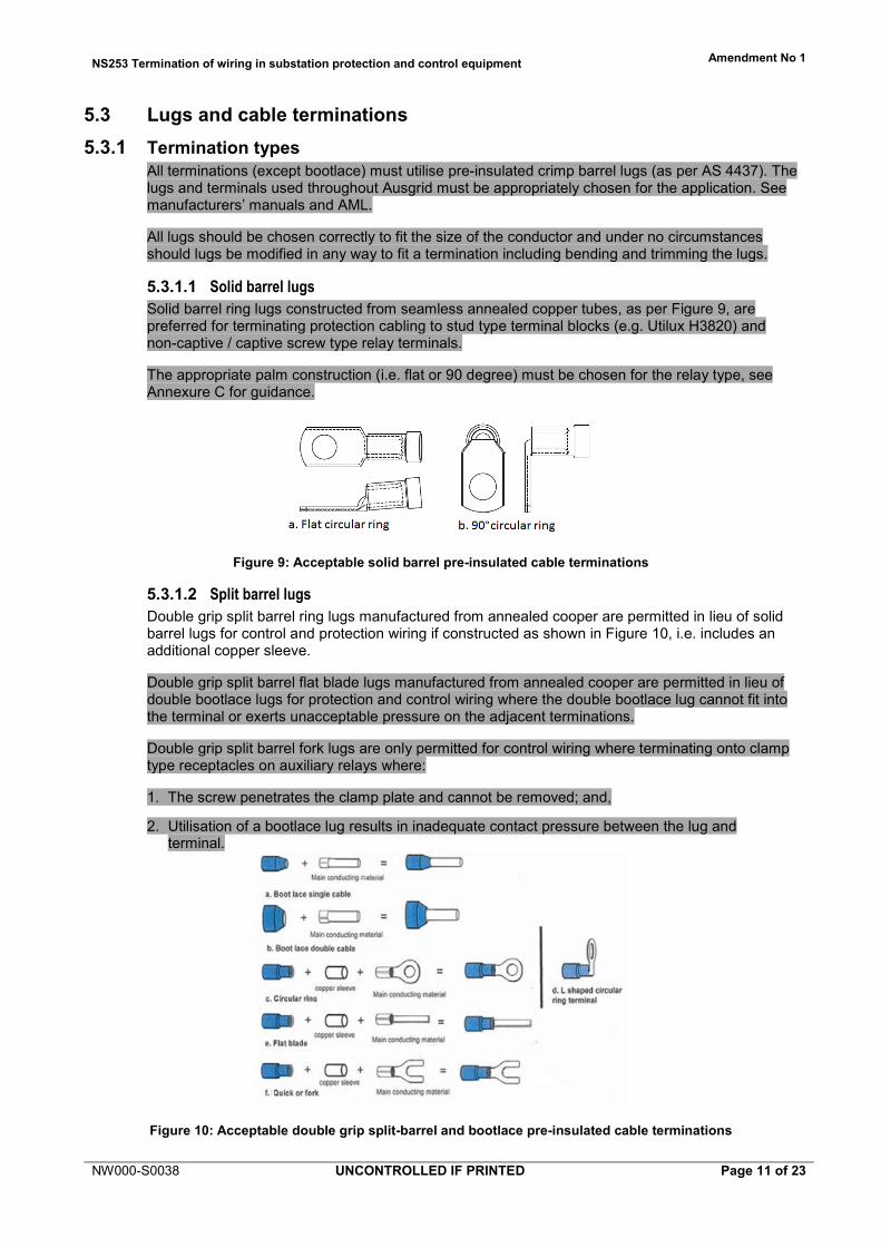
5.3.1.1 Solid barrel lugs Solid barrel ring lugs constructed from seamless annealed copper tubes, as per Figure 9, are preferred for terminating protection cabling to stud type terminal blocks (e.g. Utilux H3820) and non-captive / captive screw type relay terminals.
The appropriate palm construction (i.e. flat or 90 degree) must be chosen for the relay type, see Annexure C for guidance.
Figure 9: Acceptable solid barrel pre-insulated cable terminations
5.3.1.2 Split barrel lugs Double grip split barrel ring lugs manufactured from annealed cooper are permitted in lieu of solid barrel lugs for control and protection wiring if constructed as shown in Figure 10, i.e. includes an additional copper sleeve.
Double grip split barrel flat blade lugs manufactured from annealed cooper are permitted in lieu of double bootlace lugs for protection and control wiring where the double bootlace lug cannot fit into the terminal or exerts unacceptable pressure on the adjacent terminations.
Double grip split barrel fork lugs are only permitted for control wiring where terminating onto clamp type receptacles on auxiliary relays where:
1. The screw penetrates the clamp plate and cannot be removed; and,
2. Utilisation of a bootlace lug results in inadequate contact pressure between the lug and terminal.
Figure 10: Acceptable double grip split-barrel and bootlace pre-insulated cable terminations
NS253 Termination of wiring in substation protection and control equipment Amendment No 1
NW000-S0038 UNCONTROLLED IF PRINTED Page 12 of 23
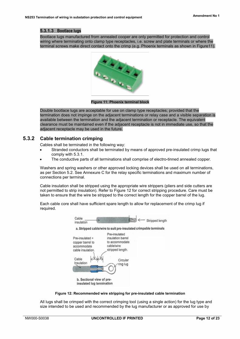
5.3.1.3 Bootlace lugs Bootlace lugs manufactured from annealed cooper are only permitted for protection and control wiring where terminating onto clamp type receptacles, i.e. screw and plate terminals or where the terminal screws make direct contact onto the crimp (e.g. Phoenix terminals as shown in Figure11).
Figure 11: Phoenix terminal block
Double bootlace lugs are acceptable for use on clamp type receptacles; provided that the termination does not impinge on the adjacent terminations or relay case and a visible separation is available between the termination and the adjacent termination or receptacle. The equivalent clearance must be maintained even if the adjacent receptacle is not in immediate use, so that the adjacent receptacle may be used in the future.
5.3.2 Cable termination crimping Cables shall be terminated in the following way: • Stranded conductors shall be terminated by means of approved pre-insulated crimp lugs that
comply with 5.3.1. • The conductive parts of all terminations shall comprise of electro-tinned annealed copper.
Washers and spring washers or other approved locking devices shall be used on all terminations, as per Section 5.2. See Annexure C for the relay specific terminations and maximum number of connections per terminal.
Cable insulation shall be stripped using the appropriate wire strippers (pliers and side cutters are not permitted to strip insulation). Refer to Figure 12 for correct stripping procedure. Care must be taken to ensure that the wire be stripped to the correct length for the copper barrel of the lug.
Each cable core shall have sufficient spare length to allow for replacement of the crimp lug if required.
Figure 12: Recommended wire stripping for pre-insulated cable termination
All lugs shall be crimped with the correct crimping tool (using a single action) for the lug type and size intended to be used and recommended by the lug manufacturer or as approved for use by

NS253 Termination of wiring in substation protection and control equipment Amendment No 1
NW000-S0038 UNCONTROLLED IF PRINTED Page 13 of 23
Ausgrid. On solid barrel lugs the crimp should be made in the middle of the top side of lug, unless otherwise instructed by the lug manufacturer, to ensure correct crimping is achieved.
On completing all crimps a visual inspection and pull test shall be carried out to ensure that there is no movement of the wire inside the ferrule within the crimped connection. The lug or stud shall then be marked with a marking pen to indicate that it has been checked.
5.3.3 Cable sheath terminations Where screened multi-core cables are required to be connected to earth they are to be terminated as per Ausgrid drawings 140401 and 140402.
Figure 13: Extract from Ausgrid drawing 140402
5.4 Exclusions 5.4.1 Splicing joining
Under no circumstances will jointing or splicing of protection (including current transformer and voltage transformer circuits) or control cables be allowed. Protection and control cabling should be continuous from source to destination.
Where continuous cables are not practical connection shall be achieved via terminal blocks firmly secured to the structure of the panel or marshalling cubicle.
5.4.2 Terminals in OEM / pre-built packages The terminals and terminations used in these circumstances must conform to AS 4437 or AS 4325.1 or an equivalent international standard.
NS253 Termination of wiring in substation protection and control equipment Amendment No 1
NW000-S0038 UNCONTROLLED IF PRINTED Page 14 of 23
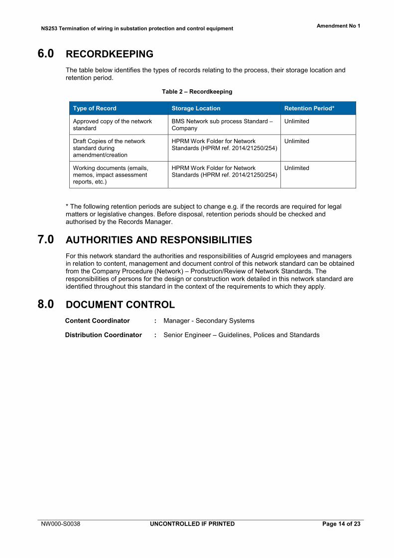
6.0 RECORDKEEPING The table below identifies the types of records relating to the process, their storage location and retention period.
Table 2 – Recordkeeping
Type of Record Storage Location Retention Period*
Approved copy of the network standard
BMS Network sub process Standard – Company
Unlimited
Draft Copies of the network standard during amendment/creation
HPRM Work Folder for Network Standards (HPRM ref. 2014/21250/254)
Unlimited
Working documents (emails, memos, impact assessment reports, etc.)
HPRM Work Folder for Network Standards (HPRM ref. 2014/21250/254)
Unlimited
* The following retention periods are subject to change e.g. if the records are required for legal matters or legislative changes. Before disposal, retention periods should be checked and authorised by the Records Manager.
7.0 AUTHORITIES AND RESPONSIBILITIES For this network standard the authorities and responsibilities of Ausgrid employees and managers in relation to content, management and document control of this network standard can be obtained from the Company Procedure (Network) – Production/Review of Network Standards. The responsibilities of persons for the design or construction work detailed in this network standard are identified throughout this standard in the context of the requirements to which they apply.
8.0 DOCUMENT CONTROL Content Coordinator : Manager - Secondary Systems
Distribution Coordinator : Senior Engineer – Guidelines, Polices and Standards

NS253 Termination of wiring in substation protection and control equipment Amendment No 1
NW000-S0038 UNCONTROLLED IF PRINTED Page 15 of 23
Annexure A - Lug Stock Codes See NS181 Approval of Materials & Equipment and Network Standard Variations.
NS253 Termination of wiring in substation protection and control equipment Amendment No 1
NW000-S0038 UNCONTROLLED IF PRINTED Page 16 of 23
Annexure B - Crimping Tools Terminations are to be crimped using methods and tools as approved by the manufacturer or as risk assessed by H-AEPS. See NS181 Approval of Materials & Equipment and Network Standard Variations.
NS253 Termination of wiring in substation protection and control equipment Amendment No 1
NW000-S0038 UNCONTROLLED IF PRINTED Page 17 of 23
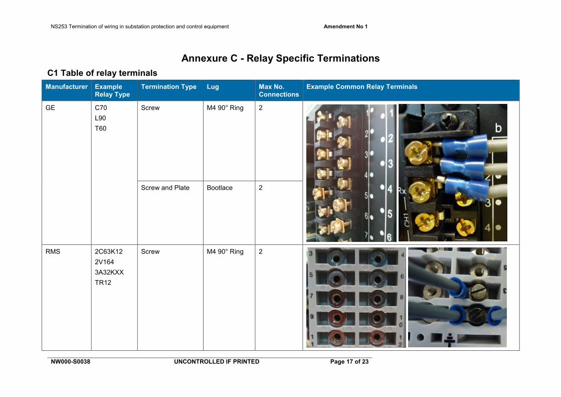
Annexure C - Relay Specific Terminations C1 Table of relay terminals Manufacturer Example
Relay Type Termination Type Lug Max No.
Connections Example Common Relay Terminals
GE C70 L90 T60
Screw M4 90° Ring 2
Screw and Plate Bootlace 2
RMS 2C63K12 2V164 3A32KXX TR12
Screw M4 90° Ring 2
NS253 Termination of wiring in substation protection and control equipment Amendment No 1
NW000-S0038 UNCONTROLLED IF PRINTED Page 18 of 23
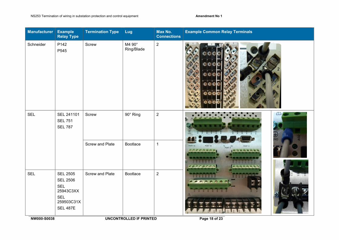
Manufacturer Example Relay Type
Termination Type Lug Max No. Connections
Example Common Relay Terminals
Schneider P142 P545
Screw M4 90° Ring/Blade
2
SEL SEL 241101 SEL 751 SEL 787
Screw 90° Ring 2
Screw and Plate Bootlace 1
SEL SEL 2505 SEL 2506 SEL 25943C3XX SEL 259503C31X SEL 487E
Screw and Plate Bootlace 2
NS253 Termination of wiring in substation protection and control equipment Amendment No 1
NW000-S0038 UNCONTROLLED IF PRINTED Page 19 of 23
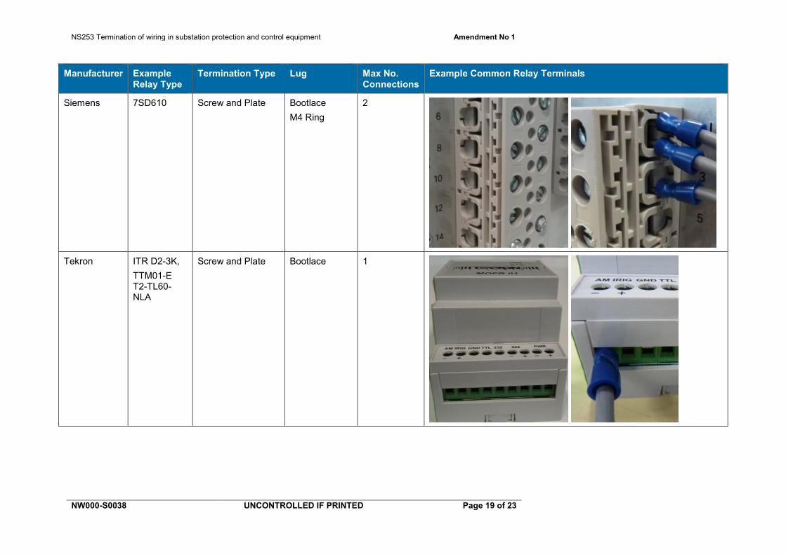
Manufacturer Example Relay Type
Termination Type Lug Max No. Connections
Example Common Relay Terminals
Siemens 7SD610 Screw and Plate Bootlace M4 Ring
2
Tekron ITR D2-3K, TTM01-E T2-TL60-NLA
Screw and Plate Bootlace 1

NS253 Termination of wiring in substation protection and control equipment Amendment No 1
NW000-S0038 UNCONTROLLED IF PRINTED Page 20 of 23
C2 Multiple lugs on one terminal If two lugs need to be connected to the same terminal, they shall be connected in the following arrangements.
Termination Arrangement
Back to back.
On top same way (one straight one right angle).
On top, offset by 90° or 180°.
Three lugs per terminal will only be accepted where the stud is long enough, and an alternate connection is not available. If required, two lugs shall be oriented back to back with the third offset by 90° or 180°.

NS253 Termination of wiring in substation protection and control equipment Amendment No 1
NW000-S0038 UNCONTROLLED IF PRINTED Page 21 of 23
C3 Unacceptable terminations Unacceptable Terminations
Insufficient gap between terminals & adjacent lugs
Wires not stripped to the correct length
Termination crimped with incorrect crimping tool
Termination not gripping the insulation
Lugs modified in any way, for example bent by hand or with pliers
NS253 Termination of wiring in substation protection and control equipment Amendment No 1
NW000-S0038 UNCONTROLLED IF PRINTED Page 22 of 23
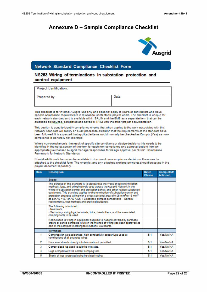
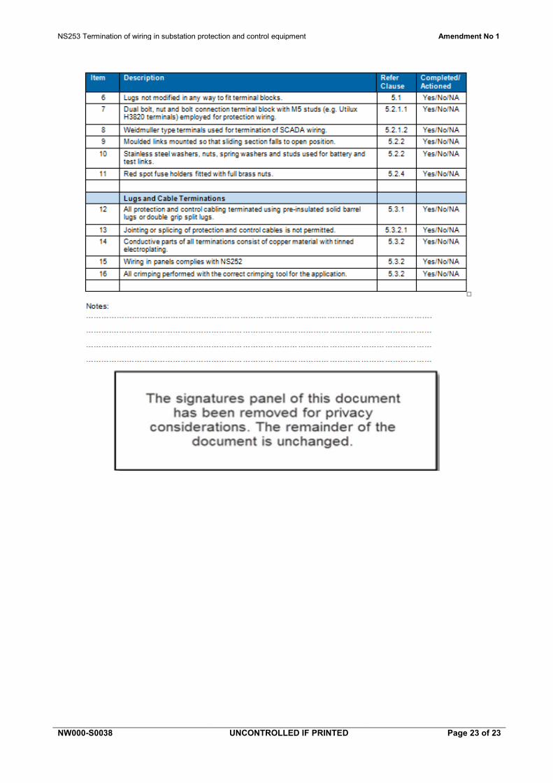
Annexure D – Sample Compliance Checklist
NS253 Termination of wiring in substation protection and control equipment Amendment No 1
NW000-S0038 UNCONTROLLED IF PRINTED Page 23 of 23