Embed Size (px)
Citation preview
National Shipbuilding Research ProgramNSRP
DISTRIBUTION STATEMENT
3D Vision for
Welder Training
and Production Welding
March, 2017
Charleston, SC

Agenda
• Summary of Project / Goals
• Progress
• Plan Forward

Project Team
• Anna Bourdais, Workforce Dev. Panel Chairwoman• Ingalls Shipbuilding,
• Frances Pearce, NSRP Program Manager• ATI,
• James S. Williford, Program Technical Officer• Ingalls Shipbuilding,
• Steven Edelson, Prime Contractor• Visible Welding
Project Overview
• Create a stereo weld video system to add depth-perception to weld-by-camera
• Test usefulness for weld training.
• Test usefulness for recruiting students.
• Test usefulness for mirror (blind) welding.
Goals• Improve training by giving students a new tool and
“aha” welding insights.
• Incrementally recruit “on-the-fence” students with modern VR-like technology.
• Improve blind-welding to shorten shipyard repair times and improve quality.
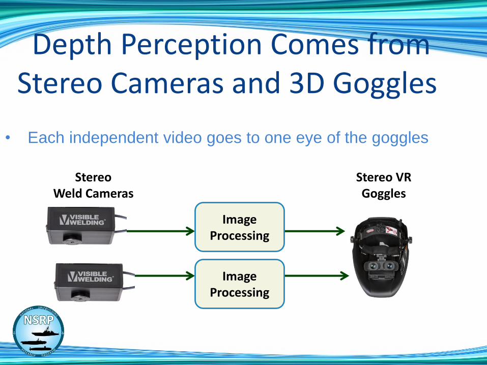
Depth Perception Comes fromStereo Cameras and 3D Goggles
• Each independent video goes to one eye of the goggles
Stereo VR Goggles
StereoWeld Cameras
Image Processing
Image Processing

Phases• Phase I: Enhanced Student Workstation
• Design, build stereo weld camera system for students.
• In-use testing of the 3D effect.
• Preliminary evaluation and improvement recommendations
• Phase II: Updated system for further testing• Update first system with improvements
• Create second system, if needed
• In-use testing and evaluation
• Conclusions and recommendations
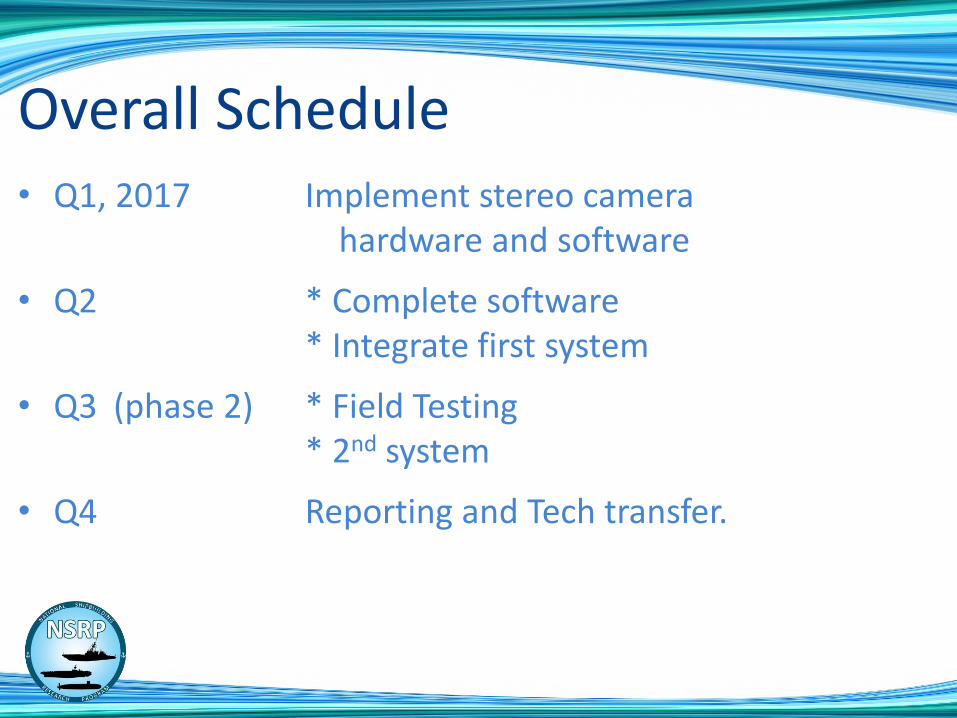
Overall Schedule• Q1, 2017 Implement stereo camera
hardware and software
• Q2 * Complete software* Integrate first system
• Q3 (phase 2) * Field Testing* 2nd system
• Q4 Reporting and Tech transfer.
Stereo Camera Fixture• Two Cameras with Lens sub-assemblies
• Electronics
• 2 Lens controllers
• Exposure synchronization
• USB hub and power
• Thumb adjustments
• Camera spacing and Convergence angles
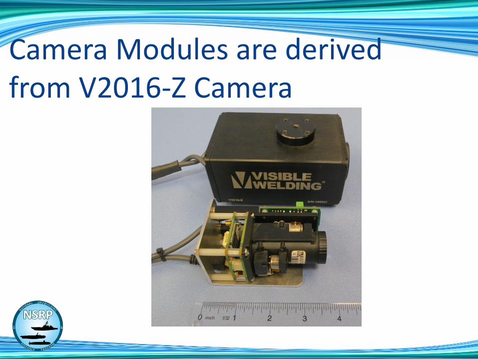
Camera Modules are derived from V2016-Z Camera
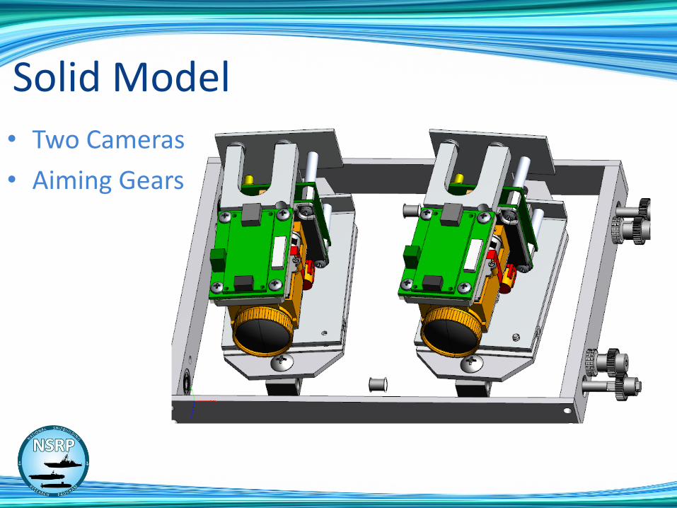
• Two Cameras
• Aiming Gears
Solid Model

Adjustment Specs• Hand adjustments (e.g. thumbscrew)
• Spacing of cameras (lens centers)
• Min: touching (lens centers approx 1.5 inch)
• Max: 4”
• Typical person’s eyes are about 2.5” apart
• Convergence angle of cameras
• Min: 0º (parallel)
• Max: 30º (cross-eyed)
Stereo Camera Lenses Must be Adjusted Identically
• We must match/track Zoom and Focus
• Zoom and Focus use stepper motors to allow repeatability
• Fixture with special software measuring lenses to build focus/zoom curves
• Create a focus/zoom database.

Zoom - Focus Fixture• Targets spaced at known distances
• Semi-automatic program gathers data

Sample Zoom Focus Curves
0
100
200
300
400
500
600
700
800
900
1000
1 3 5 7 9 11 13 15 17 19 21 23 25 27 29 31 33 35 37 39 41 43 45 47 49 51 53 55 57 59 61 63 65 67
3 in
6 in
9 in
12 in
18 in
24 in
30 in
48 in
60 in
72 in

• Use Zeiss goggles under Miller helmets
Video Under Miller Helmet
3D Vision for Welder Training
and Production Welding
NSRP PP 2017- 420
Steven Edelson
Visible Welding