Embed Size (px)
Citation preview

TRICONEX INVENSYS PROCESS AUTOMATION
15345 Barranca Parkway Irvine, California 92618 United States of America
Telephone +1 949 885 0700 Facsimile +1 949 753 9101 http://www.triconex.com
September 25, 2001
Document Control Desk United States Nuclear Regulatory Commission Washington, DC 20555
Subject: Nuclear 1E Qualification of the TRICON TMR Programmable Logic Controller (PLC) - Additional Information - TUGV Report for TRICON Version 9.5.3
References: 1. Letter, T. Martel (Triconex) to NRC, March 20, 2001, subject; Nuclear 1E Qualification of the TRICON TMR Programmable Logic Controller (PLC) Inclusion of Recent Upgrades in NRC Qualification Review.
2. Project Number 709
Gentlemen:
As part of the NRC review of the TRICON qualification documents, various product certification reports by an independent certifying agency, TOV Rheinland, were reviewed by the Staff. In earlier correspondence (Reference 1, et. al.), Triconex requested that TRICON Version 9.5.3 be considered as the 1E qualified TRICON system. Since the TOY report for this version was not available when the Staff visited our Irvine CA facility earlier this year, we agreed to forward a copy of the TOY Report and Certification for TRICON V9.5.3, when available.
Accordingly, we are enclosing for your information and review, TOV Report No. 968/EZ 105.02/01 for TRICON V9.5.3, and also a copy of the TOY Certificate for this product version. If you have any questions or wish further information, please contact me at (281) 360-6401 or Mr. Michael Phillips at (949) 885-0711.
Sincerely,
Troy Martel, P. E. Triconex Nuclear Qualification Project Director
Enclosures cc: L. Raynard Wharton, NRC
P. Loeser, NRC invensys
An Invensys Company

TUV Rheiinland/ Berlin-Bran.denbu r% �1
-t
TOV Anlagentechnik GmbH Automation, Software und Informc
" .ZERTIFIKATCERTIFICATE
Pr~fgagensland Product tested
1rypbezelennung Type designation
TRICON (Triple Modular Redundant (TMr) Controlierl Version 9.5.3; TrlStation 1131 Version 3.1.2
Oncludlng CEMPLE 3.1.2); TrlStallon MSW 3.1.2
30O613006N, 3007 (EMPII), 3504E/3504EN. 3505E/3505EN (Dig.In), 3604E/36G4EN, 3607E/3607EN (EDO). 3623T/3623TN (SDO KV), 3700. 3700A/3700AN (Al). 3704Et3704EN (HDAI). 3805E/3805EN (EAC). 421)0-3, 4201-3 (RXM). 4409 (SMM). 3515 (PT), Power Supplies. Chassis. TRICON interface Ubrary-.
HerstellIHereller I Manufacture*
3501 T1350 1TN (EDll�3501T/350ITN (EDO¢ 3564 (FSDI). 3614E, 3615E. (ESOC 3624/3624N (SDO). 3701/3701 N. 3701A 370Q6A/3706AN (NIT 4119 (EICM). 4210/421 ON. 4211/P 4609/4609N (ACM), 363.TI3636TN (EPO Termination Produc Triconex Ubrary*,
"far TriStatfln 1131 Version 3.1.2
Verwendungszweck Safety relevant appllcaions accco
Intended application DIN VDE 0116..
PrOfgnundlagen DIN V VDE 0801/01.90: DIN V VDE C
Codes and standards forming IEC 61131-2/1992; DIN VDE.01 10/01
the basis oa testing DIN EN 54, part 2/1997-12 Compot
Prfltungsergebnls Suitable for safety related applic
Test results (DIN 19250) according to the test,
sesondere Bedingungen The shutdown function and the specHiic requirements 00clh opp~lcotion. For the use
"safet Conslderation Guide-, cV documentation has to be consld
.. .. Der Protbericnt Nr. 9681EZ 105.£
' •J' Der Inhaber elnes f~jr den prOfege
berechtligt. dle mit dam Pnjifgeq Sdern otgeblldeten.PrQfzalchen zU,
TLYupB The test report No. 968/Fl 105.02 certifIcate. The holder of a valid- Ilcence cer affix the* test mark shown op=o product tested. TUV Anlagentechnik G
Gesch&ftsfetd ASI
. • 'Auttni(., Software und Informatbonste
Am Grauen Stein. 51-105 K6
2001-09-17 Poetfach 910961,51IO11KC
Datum/Date Fir mnstempel/Com-pny seal
,•1O.I O B lflU. J A2•
"iiv
11onstechnologie
Nr./No. 968/EZ 105.02/01
TRICONEX Corporation
Invensys Process Automation (IPA)
15345 Barranca Parkway USA-Irvine. California 92618 United States of Americo
S.&352E/3502EN. 350313,503EN (ýED!.
3603T/36O3TN (EDO KV). ,] •361 7E (ES0O).
3664 (FSDO), CAI).. 3703E/3703EN (EIAI),
3708E/3708EN (EITC), 411 0A/4119AN (EICM).
211 N (SPXM). 4329/4329N (NCM). 3674 (DDO FS. CARS).
L . 360T•13601TN.
IEC 1131-3 Standard UbrorVf
dclng to requirement dlass 6 (DIN V 19250) ard
801 JAI 10/94: DIN VDIE 0.116/10.8.9; .89: DIN V 19250=05.94; IEC 801 Part.)5 ients of automatIc fire detection systems.
Aons according to reauirement Classes I - 6
apart no. 968/GZ 105.02/01.
ijer software must be tested Indlvlduolry for f the TRICON controller the safety manual
lan 9 Tricon Systems, In the Triconex user red,.
/01 'om 2001-09-17 Ist Bestahdtell dleses
•.nstand galtlgen Genehmigurngs-Auswelses Ist
enstanl Ojbareinstmmenden Erzeugnisse mff..
.ersehen.
0)1 dated 2001-09-17 Is an Integral parr of this
Ificote for the product tested Is authorized to
e to products WhiCh are Identicol wiTh ther
'bif
I1." UnterschrltS ntr
ts .!
2001-09-17
Automation, Software and Info nation Technology
Type approval of TRICOI$1 version 9.5.3
Report-No.: 9681EZ 105.02/01 Date: 20011-0 17
Page 1 of 24Report-No.: 968/EZ 105.02/01

2001-09-17
Type approval of TRICON verf ;on 9.5.3
Report-No.:
Date:
Pages:
Test object:
Customer/Manufacturer:
Order date:
Order no.:
Test Institute:
Department:
TOV-Offer-No./Date:
TOV-Order-NoJDate:
InspectorS:
Test location:
Test duration:
9681EZ 105.02/01
2001-09-17
24
TRICON version 9.5.2
Triconex Corporation Invensys Process Aut 15345 Barranca Park
USA-Irvine, California United States of Amei
2001-02-05
K61431
TCV Anlagentechnik Automation, Software Postfach 91 09 51 D-51 101 K6.1n Am Grauenf Stein D-51105 K6ln
Automation, Softwar
Email dated 2001 -01
968/963017 dated FE
Dipl.-Phys. Ekkehard Dipi.-Ing. Johannes E Dipl.-Ing. Johannes I Dipl.-Ing. Jirgen Kla,
see Test Institute
February 2001 - Sep
The test results are exclusively related to the test sampi
This report must not be copied In an abridged Versior
Test Institute.
:)marion (I PA) v.ay 62618 ica
35inbH and Information Technology
and Information Technology
29
bruary 2001
Pofahl ;Uschmann 6nssen ;sen
tember 2001
as.
Without the written permission of the
Page 2 of 24Report-No.: 968/EZ 105.02/01
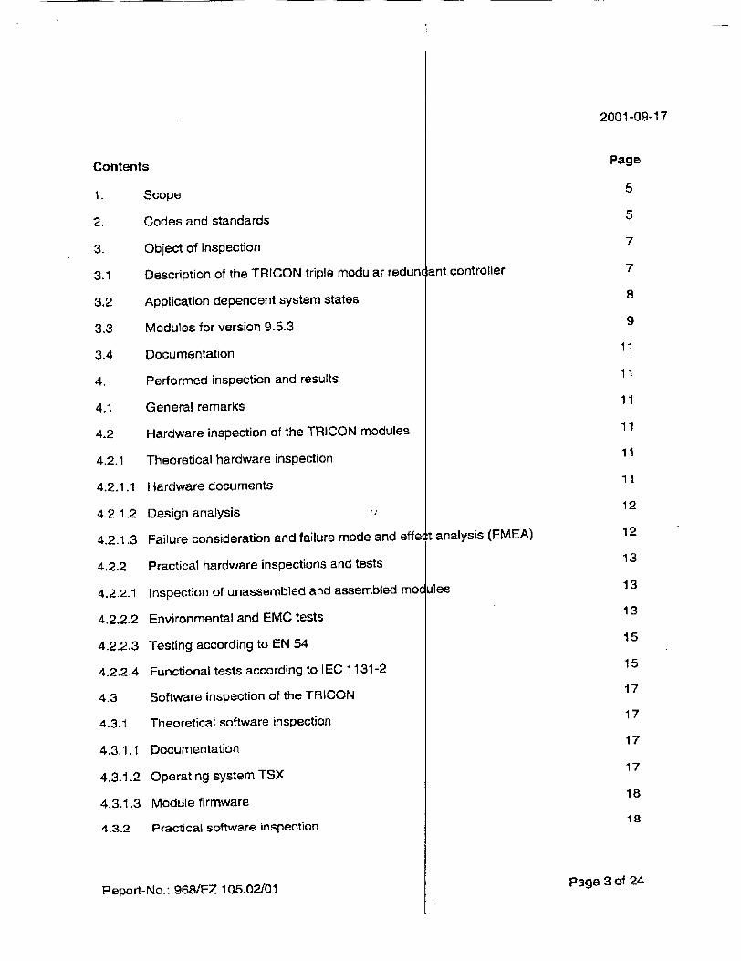
Contents
1. Scope
2. Codes and standards
3. Object of inspection
3.1 Description of the TRICON triple modular redunc
3.2 Application dependent system states
3.3 Modules for version 9.5.3
3.4 Documentation
4. Performed inspection and results
4.1 General remarks
4.2 Hardware inspection of the TRICON modules
4.2.1 Theoretical hardware inspection
4.2.1.1 Hardware documents
4.2.1.2 Design analysis
4.2.1.3 Failure consideration and failure mode and effet
4.2.2 Practical hardware inspections and tests
4.2.2.1 Inspection of unassembled and assembled moc
4.2.2.2 Environmental and EMC tests
4.2.2.3 Testing according to EN 54
4.2.2.4 Functional tests according to IEC 1131-2
4.3 Software inspection of the TRICON
4.3.1 Theoretical software inspection
4.3.1.1 Documentation
4.3.1.2 Operating system TSX
4.3.1.3 Module firmware
4.3.2 Practical software inspection
2001-09-17
lant controller
,t analysis (FMEA)
ules
Page 3 of 24Report-No.: 968/EZ 105.02/01
Page
5
5
7
7
8
9
11
11
11
11
11
11
12
12
13
13
13
15
15
17
17
17
17
18
is

Content
4.3.2.1
4.3.2.2
4,3.2,3
4.3.3
4.3.4
4.3.5
4.3.6
4.3.7
4.4
4.5
4.5.1
4.5.2
4.5.2.1
4.5.2.2
4.5.2.3
4.5.3
4.5.3.1
4.5.3.2
4.6
4.7
4.8
4.9
4.10
5.
2001-09-17
TriStation 1131
System security
TriStation 1131 validation suite
Feature tables
I EC 1131 compliant languages
Intermediate code
Tricon library functions
Black box tests
Integration testing/application program during th
Diagnostic measures
CPU
Input boards
Digital input
Analog input
Pulse totalizer module
Output boards
Digital output
Analog output
Fault insertion procedures
Measures according to DIN V VDE 0801
TRICON modules that are not relevant to safet
Test protocols, used investigation and measurif
User documentation
Summary of the results
Page 4 of 24Report-No.: 968/EZ 105.02/01
a: inspection
Ig tools
'SPage
18
18
19
19
19
19
20
20
21
21
21
21
21
22
22
22
22
22
22
23
23
23
23
24

Scope
Subject of the type approval is the programm1
version 9.5.3. The TRICON version 9.5.3 con
TSX operating system and the software TriSta
TRICON is built as a Triple Modular Redundant
In version 9.5.3 the module replacement for th(
used for some I/O boards, was introduced.
New N model numbers have been Introduce
nuclear application. The modules themselves dc
but now all nuclear module numbers can be ref•
the former type designation.
The TRICON is to be installed in safety rE
requirement class 6 according to standard
standard DIN VDIE 0116 [3].
The TRICON, equipped with fail-operational mc
related systems, where the low (0) state is
example in Fire & Gas Applications.
During the type approval it must be shown, thai
requirements for safety equipment ii.n accor,
standard DIN V VDE 19250 [1], resp. DIN V VO
All steps of the type approval are defined and (
to the Quality Assurance Guidelines QI•
Automation, Software and Information Technol(
2. Codes and standards
[1] DIN V 19250/05.94 Grundlegende Sicherheitsbetrachtungen
Fundamental Safety Aspects To Be Conm
Control Protective Equipment
[2] DIN V VDE 0801/01.90 Grundsitze f~r Rechner in Systemen mit
Anderung Al : Oktober 1994
Principles For Computers In Safety Relal
Amendment All: October 1994
2001-09-17
6ile logic controller (PLC) TRICON sts of the TRICON hardware, the
ion 1131 and TriStation MSW. The
±MR) Controller.
,obsolete microprocessor, which is
: for Tricon modules intended for
'not differ from the original module,
renced by attaching the letter "N" to
levant areas up to and including
:)INV 19250 (1] and according to
dules, will also be installed in safety
ypically not the safe state, as for
the TRICON version 9.5.3 fulfils the
lance with requirement class 6 to E 0801 [2].
locumented by a test plan according
1E 27 of the Business Sector
wgy of TUV Anlagentechnik GmbH.
[Or MSR-Schutzeinrichtungen
idered For Measurement And
Sicherheitsaufgaben
ed Systems
Page 5 of 2 4
Report-No.: 968/EZ 105.02/01
[3] DIN VDE 0116/10.89 Elektrische Ausrbstung von Feuerungsanle
Electrical Equipment Of Furnaces
[4] 1 EC 1131 -part 2/1998 (Draft), EN 61131-21
Programmierbare Steuerungen
Teil 2: Betriebsmittelforderungen und Pr0fi
Programmable Controllers
Part 2: Equipment requirements and test
(5] DIN EN 50178/04.1998 AusriJstung von Starkstromanlagen mit ek
Electrical equipment for use in power instz
[6] DIN IEC 68 Grundlegende Umweltprl3fverfahren
Basic environmental testing procedures
[7] EN 50081-2:1993 Elektromagnetische Vertraglichkeit (EMV, Teil 2: Industriebereiche
EMC Requirements, Generic emission standard, industrial eny
[8] EN 61000-6-2:1999
Elektromagnetische Vertr~glichkeit (EMV
St6rfestigkeit im Industriebereich
EMC requirements Generic immunity standard, industrial en
[91 DIN EN 54, Teil 2, Januar 1990 (Entwurf Bestandteile automatischer Brandmeldur
Components of automatic fire detection E equipment
[10] Europaische EMV Richtlinie 89/336/EW( European EMC-directive 89/336/EWG
2001-09-17
gen
May 1995
ingen
!ktronischen Betriebsmitteln
llations
.Fachgrundnorm St~raussendung;
ronment
- Teil 6-2: Fachgrundnormen
Vironment
Draft) ,gen, Brandmelderzentralen
Vstems; control and indicating
Page 6 of 24Report-No.: 968/EZ 105.02/01
i

3. Ob ect of inspection
3.1
A TUV
2001-09-17
Description of the TRICON triple modular redindant controller
The TRICON is a fault tolerant controller ba (TMR) architecture. The basic TRICON archite from the input modules through the Main Proces
Every I/O Module houses the circuitry for three input modules reads the process data and pass Main Processor. The three Main Processors using a proprietary high-speed bus system calle(
Once per scan the three Main Processors sync two neighbours via the TRIBUS. The TRIBUS output data, and sends copies of analog input dz
The TRIBUS also sets flags to indicate discr( during the TRIBUS comparison and voting opi these flags to diagnose problems on the input m
The Main Processors execute the control calcu
are sent to the output modules. In addition to
votes the output data. This is done on the outp
possible, to correct any errors that could occur b
final output driven to the field.
input
;ed on Triple-Modular Redundant lture is fully triplicated throughout, ;Ors to the output modules.
independent legs. Each leg on the ý-s that information to its respective ,an communicate with each other the TRIBUS.
ironize and communicate with their votes digital input data, compares ta to each Main Processor.
pancies and disagreements found rations. The Main Processors use
)dules and the Main Processors.
ations and compute outputs which ipting the input data, the TRICON At modules as close to the field as Atween the Main Processor and the
Outoo Tren,*tC011a
Page 7 of 24Report-No.: 968/EZ 105.02/01

By these measures, especially by complete co
three legs, it is guaranteed, that each active
least two cycle times.
The digital input modules contain three compl
with associated input circuitry which provide
digital inputs connected to the module.
The digital input module checks for "stuck ON"
input on each 110 leg. The "stuck ON" test rout
the optical isolation equipment on each input
reading through the optical isolation circuitry. Tt
3504E checks also for "stUck-OFF' conditions.
The digital output modules contain three i
receive commanded outputs from the three Ma
output to a fault tolerant "quad" output voter cir
of two independent switching paths with two sw
ensures the correct output even in the presen•
three microprocessors on the digital output moa
the output voter circuit to check for shorted or o
The analog input modules are also fully triplic9
voltage references which allow the analog input,
The TRICON provides two physical..11O slots
system. If a fault is detected on an I/O module,
effecting the system operation by inserting
provided next to the faulty module.
When the newly inserted module takes over
can be removed for repair. The TRICON syste
of a faulty module if a spare module is pro
functional I/O slot.
Each chassis houses two power supply moc
redundant configuration so that each powe
supporting the power requirements of all the r
every I/O module derives power from both pow
regulators. Thus in the event of a power supl
continue to operate as they can derive power ft
3.2 Application dependent system states
From all possible applications where the tripl
there are two typical classes:
TUV 2001-09-17
riparison of all results between the
0it is found and voted out after at
stely independent microprocessors
Vhree independent readings of the
or unsafe conditions on each digital
ne periodically zeroes the inputs to
and checks for proper zero input
e High Density Digital Input Module
dependent microprocessors which
ri Processors and send each digital
uit. The output voter circuit consists
crhes in each path. This voter circuit
6 of a single fault in the voter. The
ule continuously run diagnostics on en switches.
ted and each leg contains multiple to be calibrated automatically.
for each functional I/O slot in the
the module can be replaced without
spare module in the second slot
peration, the inactive faulty module n also provides automatic hot repair
6ided in the second i/O slot of the
lJes. They are arranged in a dual
,supply is individually capable of
iodules in that chassis. Each leg on
er supplies using independent power
)!y failure all legs of all I/O modules
d.m the other power supply.
icated Triconex PLCs may be used
- Emergency Shutdown Systems (ESD systems)
Continuous Run Systems (CR systems), e. .. Fire & Gas Applications.
Report-No.: 968/EZ 105.02/01
0�
Page 8 of 24

For an ESD system, depending on the applical
continue operation with only one channel, if the
is true for applications equal to or higher than
process to the safe state than to continue c
operation.
This is not true for CR systems (e. g. Fire & (
safe state in these systems. Therefore a typica
operation with only one channel after losing th
not increased by shutting the system down. H
channels to one channel there must be a high
the system state.
The triplicated TRICON architecture consists
consists of one input leg, one main processo
controller is designed to continue operation aft'
in an input leg, in a main processor, or in an (
the application program; the programmed ]1
detected failures.
A set of system variables is implemented withii
of the system. These variables allow an exact
specific variables, there are variables built int
how many "sane" channels, from input thro
working in the system. The calculation for thi
loss of an 1/0 channel, a main. processor, c
variables indicate if the system is operating, fr
channels, two channels or one channel. The
application- (user-) program for either ESD or I
The user program has to be developed to con
of the TRICON. The TRICON user docume
these variables for the different -applicati,
applications.
Extensive self tests are executed internally to E
3.3 Modules for version 9.5.3
The following modules are part of version 9.5.
Model-No. Name of module TiStation 1131 vers
TriStation MSW 3.1.
IEC 1131 -3 Standa' TRICON Interface L Triconex Library ver
Report-No.: 968/EZ 105.02/01
A TUV
2001-09-17
on class, it may not be allowed to
ither two channels have failed. This
1•ss 5. It is safer to shut down the
}eration with only one channel in
ias Systems). Typically there is no
fire detection system may continue
):two other channels- The safety is
,Wever, after degradation from two
wr alarm level to the operator about
of three channels. Each channel and one output leg. The TRICON
!r failures. These failures may occur
utput. All failures are transparent to
jic will be executed regardless of
the TRICON to determine the state
ault localization. Besides these fault
the TRICON system to determine,
:oh main processor to output, are
de variables takes into account the
, any combination of these. These
'm the input to the output, with three
:allow an easy configuration of the
ite & Gas Applications.
iider the different states of operation
itation gives guidelines how to use
ins in either ESD or Fire &Gas
low exact failure localization.
Page 9 of 24

A TUV
2001-09-17
Model-No. Name of module
3501T/3501TN Enh. Digital Input 115 I;AC/DC HighKV
3502E/3502EN Enh. Digital Input 48 VC/DC (EDI)
3503EJ3503EN Enh. Digital Input 24 V AC/DC (EDI)
3504E/3504EN High Density Digital In )Ut, 24/48 VDC (HDI)
3505E/350SEN Enh. Digital input 24 V C, low Threshold (Dig. In)
3515 Pulse Totalizer Modul( (PT)
3564 FSDI, Fail Safe Digital Ihput 24 V (FSDI) 3601T1/3601TN Enh. Digital Output 115 V AC non commoned HighKV (EDO)
3603T/3603TN Enh. Digital Output 12 V DC HighKV (TSDO)
3604E/3604EN Enh. Digital Output 24 V DC (EDO)
3607E13607EN Enh. Digital Output 48 V DC (EDO)
3614E Enh. Superv. Digital 0 tput 24 VDC (ESDO)
3615E Enh. Superv. Digital 0 tput 24 VDC, Low Power (ESDO)
3617E Enh. Superv. Digital 0 tput 48 VDC (ESDO)
3623T/3623TN Enh. Digital Output 12 V DC Supervised HighKV (TSDO)
3624/3624N Supervised Digital Ou ut 24 V (TSDO)
3636T/3636TN Relay Output Dry cont ct HiahKV (ERO)
3664 Fail Safe Digital Outp .24 V (FSDO)
3674 Fail Safe Digital Outp 24 V (DDOFS, CARS)
3700, 3700N3700AN Analog Input (0-5 VD (AI)
370113701 N, 3701A Analog Input (0-10 VD ) (Al)
3703F_/3703EN Isolated Analog Input odule 0-5/0-10 V DC (EIAI
3704E/3704EN Analog Input.(0-5/0-1 VDC) (HDAI) 3706A/3706AN Non Isolated Thermoc 3uple Input (NITC)
3708E/3708EN Isolated Thermocouph input Module (EITCO
3805E/3805EN Enhanced Analog Out Ut Module (4-20 mA) (EAO)
4119, 4119A/4119AN Enhanced Intell. Corn i. Module (EICM) 4200-3 Primary RXM Module RXM) 4201-3 Remote RXM Module RXM)
4210/421 ON Primary Single Mode I~iber Optic RXM (SRXM),
4211/4211 N Remote Single Mode Fiber Optic RXM (SRXM)
4329/4329N Network Communicati h Module (NCMI
4409 Safety Manager ModL e (SMM) for Honeywell's Universal Control Network (UCh )_
4609/4609N Advanced Communi tion Module (ACM)
8110 High Density Main Ch issis
8111 High Density Expansi n Chassis
8112 High Density Remote iJpansion Chassis
8310 120 VACNDC High D nsity Power Module
8311 24 VDC High Density 3ower Module�1 9 2.•1l MAC Hidh LDernsm
Pnw~r Sinnilies_________________ qt n.-. ----.--
ChassisTermination Products
TermiationProduts
Page 10 of 24Report-No.: 968/EZ 105.02/01
Qla 19 230 VAC High Dens
Chassis
Power module
#.

3-4 Documentation
All the documentation related to revision 9.,r electronic form.
The specific revision levels are documented in t!
6200003-120 SRD 9-5-3 Release (for overall sy 8 pages
6200097-006 SRD TS 1131 (for TS 1131), 12. S
4. performed inspection and results
4.1 General remarks
The inspection of the Tricon was done in a approval consisted of
- checking new boards, as they became availa
- checking of new hardware and firmware revic
spot-checking of Triconex internal quality me,
checking of product updates
in the following chapters the procedure is descri
4.2 Hardware inspection of the TRICON module-_
4.2.1 Theoretical hardware inspection
4.2.1.1 Hardware documents
For all modules the following documents were c
functional description, data sheets
hardware design specification
input, output and bus specifications
schematics
detail PCB
layouts
material/part list
TUV 2001-09-17
.3 is available as printout and in
ie following release definitions:
item), release 1.2, September 2001,
3ptember 2001, 18 pages
incremental way. This incremental
Dle
ions
ýsures to ensure constant products
,ed.
iecked
Report-No.. 968/EZ 105.02/01 Page 11 of 24
- test specification
- test procedures
- PAL equations
- fault insertion procedure
- assembly, module
- approved vendors and manufacturers list (pa
- quality assurance procedure for this documei
The documents are complete and correct. All another and with the modules. The data-she' needed for installation to any application.
4.2.1.2 Design analysis
Base for the design analysis are the concel
schematic. The design is checked to be fit for pL
Hardware sections that are equivalent among d thoroughly. The corresponding sections of tt without major further inspections.
Used ASIC circuitry's were inspected for compa
The functions of the modules according to th
checked within the functional and en, IEC 1131-2 [4].
No design problems were found during this proc
4.2.1.3 Failure consideration and failure mode and c
The safety of the TRICON controller systems structure and on the high effective diagnostic operating system.
Based on the structure and diagnostics the ability to control any single fault and to detect d(
The fault behaviour of the TRICON system and method of an FMEA (Failure Mode Effect Analy
Report-No.: 968/EZ 105.021010=
TUV 2001-09-17
is, PCBs)
itation
documents are consistent with one ýts contain all relevant information
it papers together with the actual I rpose.
fferent modules were checked once ie derived module were accepted
:ibility with the surrounded areas.
a manufacturers specification were tironmental tests according to
ess.
Ifect analysis (FMEA)
depends on the redundant (triplex)
!ystem implemented to the TRICON
RICON controller system has the
rmant faults.
[of the modules was checked by the
Pis).
Page 12 of 24

For each fault assumed it was checked by analN of the relevant portion of the diagnostic systen detected respectively. The results of this theore fault insertion lists of the manufacturer, whicf insertion procedure carried out on a TRICON syý
Faults for which the FMEA method did not leac not considered by the fault insertion procedure presented to the manufacturer for further steps c
It has been proved that all assumed and inserte
structure or by the fault diagnostics respectively.
4.2.2 Practical hardware Inspections and tests
4.2.2.1
A TUV
2001-09-17
sing the behaviour of the system or I if the fault would be controlled or :ical inspection were compared with :are based on an extensive fault
item.
['to an clear result and which were )f the manufacturer were listed and ,f the fault insertion procedure.
d faults are controlled by the triplex
Inspection of unassembled and assembled rModules
For all modules the following was inspected:
1. Visual checks of the assembled board
- identification of the modules
- consistency between modules and modfal documentation
- quality of manufacturing
- clearness - correctness of soldering - positioning of the components
2. Visual checks of the unassembled boards 1PCBs)
inspection of the clearance and cre, requirements of EN 61131-2 with overvoltage category II and pollution de
quality of manufacturing
The clearance and creepage distances of the rr standard EN 61131-2.
,page distances easpect to the gree 2
according to the working voltage,
odules fulfil the requirements of the
The manufacturing of the modules is correct anc without any visual faults.
4.2.2.2 Environmental and EMC tests
The following environmental tests according IE4 1131-2 [4] were laboratory of TUV Rheinland Anlagentechnik G rbH, Cologne.
Report-No.: 968/EZ 105.02/01
carried out in the
Page 13 of 24

A TUV
2001-09-1 7
The performed tests are listed in the following t le:
Title Used standard Use severity PLC
operation
Cold, test Ab IEC 60068-2-1 -25°t;o 96 h no
Dry heat, test Bb (Bc) IEC 60068-2-2 +70'G, 96 h no
Shock, test Ea IEC 60068-2-27 half irie, 15 g, 11 Ms, yes 3 sh ,cks in each axis
Change of temperature, IEC 60068-2-14 low emperature: 50 C yes
test Nb high temperature: 550C 5 cy'les, 1 degree/minute
Damp heat. IEC 60068-2-30 high temp.: 55'C, non-condensing cyclic test Ob var-,nt 2, cycles: 2
cycl I no cycl 2 yes
Vibration, test Fc IEC60068-2-6 ran 1: 10-31 Hz @ 1 mmpp, yes ran 2: 31-500@ lg spa d: 1 oct./min. cycl s: 10 in each axis
Electrostatic discharge lEG 801-2 leve 3: 8 kV (air) yes 4 kV (contact)
> 1 positive and > 10 negative discG arges for each test point R = 330 Ohm
=C 150pF
Burst EN 50 082-2 lave s: yes IEC 801-4 + si 'Mal lines. (capacitive coupling)
a alog and digital 10-lines (fig 5): class 3 (1 kV)
±2 kV + p wer lines: (direct coupling)
AC or DC: class 3 (2 kV) dur tion: > 30 sec.
Surge IEC 801-5 pow ýr lines 110 V: yes Sevel 3: (2 kW, 4 WV PE)
Shape of pulses: pow 3r lines 24 V, signal lines.
1,2 ps/50 ps free running anal g and digital I10-lines:
8 ps/20 ps shorted Ii ývel 2: (1 kV, 2 kV PE) pul s:
AG: : @ 0,90,270 Degree. DC: 5 positive and 5 negative. Ste s of 250 Volt until target level
7- d5 UP eConducted disturbance EN 50 081-2
EN 55 011: KI A0,1- - 0,5 MHz
0,5 4 5 MHz
0 MHz
79 dl30V (OP) 66 dBpV (Av) 73 dBpV (OP) 60 dBpV (Av) 73 dBPV (QP) 60 dBpV (Av)
Report-No.: 968/EZ 105.02/01
yes
Page 14 of 24

The tests of radiated and conducted emis; compliance testing for the European CE mark. included all representative modules.
4.2.2.3 Testing according to EN 54
The standard EN 54 "Components of~automati( indicating equipment' [9] was chosen as the g for use in fire and gas applications. CharactE normally no safe state of a fire&gas signalling safety is not increased by removing power from
TUV 2001-09-17
ions was done as a part of the rhe test system used for this testing
-fire detection systems; control and lideline to qualify the TRICON also
ristic for these applications is, that :central is defined. Specifically the
a fire&gas central.
The set of tests, which is defined in this st4ndard, was included in the earlier
described suite environmental and electromagnotic compatibility tests.
The test high humidity (95 % humidity), 21 day i at 400 Celsius. without operation, was done to show, that the equipment can witht rand high environmental stress.
4.2.2.4 Functional tests according to IEC 1131-2
The behaviour of the approved modules was tE in the manufacturers documentation with re standard IEC 1131-2.
For discrete input modules:
- test and verification of input characteristics
- test of the thresholds for 0/1- and I/0-transitli
- reversal input polarity test
Report-No.: 9681EZ 105.02/01
sted according to the data specified spect to the requirements of the
Page 15 of 24
Title Used standard Us severity PLC operation
Radiated disturbance EN 50 081-2 30 - 230 MHz 40 dBEuV/m yes EN55011 :KIA 230- 470MMHz 47dB/pV/m
470 - 1000 MHz 47 dBpV/m
Conducted immunity EN 50 082-2 0,1 -80 MHz > 240 steps per dec. yes ENV 50 141 10 (rms)
Moe ulation AM 80 %. 1 kHz
Immunity radiated fields EN 50 082-2 80 - 1.000 MHz > 240 steps per dec yes 10 W/m horizontal and vertical Spo frequency 900 +/- 5 MHz Moe ulation Pulse, 50 % duty rate
200 Hz repetition rate
Voltage clips EN 50 082-2 - 30 % 10 ms yes EN61 000-4-11 -95% 5.000 ms
+/- 0 % > 1 minute -60% 100 ms
•q

- inspection of sufficient isolation between leg
- di-electrical withstand test/Hi Pot test with rE module
- check for the right status indications
- check of the right switching over to hot stand
For discrete output modules:
A TUV
2001-09-17
iputs (input impedance)
spect to the working voltage of the
by modules in cases of faults
test and verification of the output characteristos
test of the specified values for current ranges and voltage drops
- test of the behaviour under overloaded situat
- di-electrical withstand test/Hi Pot test with specification respectively
check for the right status indications
dns respect to the working voltage or
- check of the right switching over to hot stand tby modules In cases of faults
For analog input modules:
test and verification of input characteristics
- range
- resolution/accu racy
- overrange protection
inspection of sufficient leg isolation
- check for the right status indications
- check of the right switching over to hot stand
For the counter modules the right counting fu connecting the inputs of the module to two module. The pulse converter module converte( pulse generator to a low pulse with a minimL pulse with a minimum pulse width. In additi respectively were varied by variable resistors.
All 32 counter of the. module were connected Different alarm level values were set for all reached the alarm level the point number and with a time stamp. The right counting was che time distance between 2 following print outs of time.
by modules in cases of faults
iction of the module was tested by iulse outputs of a pulse converter I the incoming pulse of an stabilized m pulse width (300 ps) and a high in the high level or the low Level
alternatively to the pulse converter. 12 counter. Every time if a counter the level were printed out together
aked by comparison of the stamped the same counter with the expected
Page 16 of 24Report-No.: 9681EZ 105.02/01

4.3 Software Inspection of the TRICON
The correct operation of the TRICON depends several areas of the TRICON.
The software of the TRICON can be dIvIded ir editor MSW and TriStation 1131) and the hardware.
4.3.1 Theoretical software Inspection
During the theoretical software inspection all sF the internal communication protocols were inve the documents and to find deviations I documentation.
TUV 2001-09-17
)n correct software, which is used in
the development software (ladder;oftware/firmware on the TRICON
ecifications for the software and for stigated to prove the correctness of )etween specification and other
The inspections were carried out on the basis ol the following documents:
- Triconex Software Coding and Practices Guit
- TriStation 1131 software requirements specif
- Specification and Test documents for each rr
- CFLOW evaluations, partly contained in the
- ProMet evaluations for assembly programs
- Source code in machine readable fdrm
4.3.1.1 Documentation
The code specific documentation (besides the development) is divided into the main areas of firmware for the I/O modules and the software user interface.
Object of closer investigation was the TSX or firmware documentation. Here it was checki sufficiently described in a specification docui implemented according to the specification. Als verification procedures for the I1O modules anc investigated.
The documentation is sufficient and complete.
4.3.1.2 Operating system TSX
The operating system resident in the TRICOI system is responsible for the basic functions internal clock and all fundamental functionsboards on the TRICON.
Report-No.: 968/EZ 105.02/01
leline cation odule lescription documents
general documentation on software operating system TSX for TRICON, TdStation 1131, which provides the
erating system and the I/O module -d, that every software module is Y1ent and that the source code is o6 the documents describing the test I the Main Processor modules were
I 'is called TSX. The TSX operating ts for example keeping track of the t:is located on the main processor
Page 17 of 24

By analysis it was investigated, that TSX ens between the Main Processors every cycle. Bi leads to a different result in one of the channi Processor operation mode.
4.3.1.3 Module firmware
The firmware of the modules is partly develo assembly language. The specification doc investigated to check, that the firmware is able t high diagnostic coverage to detect broken hardware.
TUV 2001-09-17
ares the comparison of all results this measure every failure which
!Is is detected in the 2 and 3 Main
)ed in the language "C", partly in iments for each module were )!provide the function and to have a )arts and other problems in the
Static analysis tools were used to investigate tho final coded software.
The firmware of all modules was investigated witl positive result.
4.3.2 Practical software Inspection
During the practical software inspection it v programs are in conformance to the specificati( the following procedures.
4.3.2.1 TriStation 1131
TriStation is the PC based software to devf programs. It was developed to conform to tl programming languages.
It forms the user interface to the system during program. All programs, which were used for the developed using TriStation during th e inspectio software was checked thoroughly together wit programming languages (ladder diagram, functic
Fas shown that the implemented ins. This was done as described in
ilbp, compile and test application e PLC standard IEC 1131-part3,
the development of the application hardware and software tests, were
n. By this procedure the TriStation i the functionality of the provided rn block diagram, structured text).
The inspection of TS1131 began in the eary project state and included the assessment of the installed quality assurance m *thods for TS1 131.
4.3.2.2 System security
TnStation 1131 provides a security system tha with regard to editing, library changes, TF operations.
It is possible to define 10 levels with a different be introduced into the system by name and privi is checked by a password.
defines users and their privileges ICON state changes and other
set of privileges. Every user has to ege. The access to TriStation 1131
Report-No.: 968/EZ 105.02/01 Page 18 of 24

A project log is kept, so that every change to tV the originator.
TUV 2001-09-17
3 application can be traced down to
The security information is stored together with Jhe other program data.
The security system is sufficient to protect appi unauthorized changes.
4.3.2.3 TriStation 1131 validation suite
A validation suite was developed to prove the This development was done by the manufacti was brought up at TUV in Cologne to be able to
The validation suite is divided in two major partV is performed by automated tools. The results a protocol files.
The validation suite worked and did not show f 1131 or the TRICON.
c4ation programs from unintended or
,orrect operation of TnStation 1131. ir er (Triconex). A mirror installation repeat the testing.
•, the compiler and the library test. It in be inspected by means of textual
aults or failures within the TriStation
No safety critical errors or anomalies of TriStati4n 1131 software were found.
4.3.3 Feature tables
The IEC 1131 does not require, that a-languagc in the standard. It is mandatory however to ha feature table. This feature table summarizes, wl implemented.
, has all elements, which are defined ve all elements listed in a so called iich element of the 1131 language is
These feature table can be found in th ; document TriStation, Software requirements specification, doc. no. 6200033-0(11, Revision 1.3, 1997-01-19.
4.3.4 IEC 1131 compliant languages
From 5 languages described in the standard 1E chosen for TriStation 1131. A special feature from different languages can be compiled toge From the possible languages the following are ii
- Ladder diagram
- Function block diagram
- Structured text
4.3.5 Intermediate code
The application program, which is written in on transformed in intermediate code, which is reac code is Pascal-like and is used by the comp loaded into the TRICON.
Report-No.: 968/EZ 105.02/01�1�
6 1131-3 there are three languages of TriStation 1131 is, that modules ther to form an application program. niplemented:
a:of the IEC 1131 languages, will be able ASCII format. This intermediate ler to produce the binary, which is
Page 19 of 24

TUV 2001-09-17
The production of the intermediate code is transparent for the user. The intermediate code files were checked during thee software inspection.
This is a very powerful feature in tracing back necessary. Specifically the transformation from line-by-line code can be investigated.
Each project is defined by one project file. The
and includes all project dependent information.
No anomalies were found.
- 4.3.6 Tricon library functions
The TRICON library elements can be used with to develop functions, function blocks, and prognr controller.
The TRICON Library consists of the categories:
- Fire - Ladder - Logic - Math - Print - Process - System - Time - Utility
The Library to connect to the system services basic functions of TRICON controller were not compliant programs. Some functions have beei within the TSX-system to the library.
application programs, should it be graphical programming to traditional
3roject file is built as a container file
any of the editors in TriStation 1131 ims for downloading to the TRICON
of TSX is mainly an interface. The changed in order to process 1131 iported from assembly/C-language
All elements are checked out by means of TS1 431 validation suite.
No errors were found.
4.3.7 Black box tests
The TSX Functional Verification Procedure de Lcribes the checks of the TRICON. The procedure was repeated for some specific 4ituations:
- Hard errors on I/O module - Transients on I/O bus - Download changes - Key switch operation - Rack maintenance variables.
Report-No.: 968/EZ 105.02/01 Page 20 of 24

TUV 2001-09-17
The rest of the documented tests were inspectep 1in a walk through procedure.
Additional tests, which were made independ included diverse manipulations on the PLC:
- withdrawal of I/O modules - disconnection of power supplies - shorting of the output signals - shorting on the serial lines.
The Black box testing included different progr
environmental and EMC tests.
The result was as expected.
?nt of the documented procedure,
ýms, which were developed for the
Integration testing/application program durilog the inspection
Several application programs were developed ' modules. The programs were active during all By these programs the correct and prc dimensioning and software algorithms was between channels and checks against expec behaviour was logged constantly with an event
4.5 Diagnostic measures
On all boards functional parts are subject tc components supervised include watchdog circL voltage regulators, bus driver circuits, opt multiplexers.
o show the correct behaviour of the functional and environmental tests.
per implementation of hardware bhecked by means of comparison
:ed results. In addition the internal ogger.
.very sophisticated self tests. The litry, ROM, RAM, dual-ported RAM, nCoplers, voltage references and
In the following paragraphs board specific diagn ostics are listed.
4.5.1 CPU
All used microprocessors perform extensive parts, specifically the TriBus, are subject to sevi
4.5.2 Input boards
On all input boards the diagnostics are design inputs as far to the field as possible to verift control program.
4.5.2.1 Digital input
For the digital input board special tests were im the "0" level. Several other tests check for crosf
Report-No.: 968/EZ 105.02/01
self tests. In addition all functional ýral diagnostic tests.
ed in a way, to stimulate the actual the correct signals passing to the
p~emented to detect the ability to see talk effects on a bit level.
Page 21 of 24
4.4
3!

4.5.2.2 Analog input
TUV 2001-09-17
On the analog input board several reference vc Itages are used to verify the correct operation of the analog to digital converters and the multiplexers.
4.5.2.3 Pulse totalizer module
Due to the redundant structure (triplex) the m available. The online diagnostics implemente diagnostic implemented on the enhanced DI inputs are not auto-tested. The dynamic behai on the inputs or counter circuits immediately against the data of the other legs. The corn sufficient to fulfil the range of diagnostic coveraý
4.5.3 Output boards
On the output boards measures are implemente change the output, when it is demanded.
4.5.3.1 Digital output
Digital outputs are subject to a pulse test. Dur checked for the ability to switch. On the supen measures are implemented, which do not ne correct operation.
4.5.3.2 Analog output
On the analog output board three separate out[ it can drive the output on its own. The conti between the legs on a regular basis. The compared against the commanded values.
4.6 Fault insertion procedures
The manufacturer Triconex provided the procedures, which are done during the devs modules.
These fault insertion procedures were objecl some of the fault insertion procedures was doni
In addition the fault Insertion lists provided b additional lists with fault to be implemented.
The finally released modules could detect all i faults are diagnosed by the operating system a to initiate the appropriate actions.
Report-No.: 968/EZ 105.02/01
•dules are fault tolerant and highly j: on the module is similar to the
nodule with the exception that the iour of input pulses discovers faults )y verifying the input data of a leg :lete set of diagnostic functions is e (safe failure fraction) of > 90 %
d to verify the possibility to switch or
ng the pulse test the final switch is rised digital output modul diagnostic ed to switch the outputs to verify
iUt drivers are implemented. Each of 61 of the output points is changed dutput values are read back and
documentation of fault insertion
I6pment cycle of new or changed
to investigation. Spot-checking of
Triconex the inspectors prepared
rplemented faults as required. The
id are available to the user program
Page 22 of 24a

4.7 Measures according to DIN V VDE 0801
The measures which are necessary for DIN V VDE 0801 Appendix Al are fulfilled. Th, detect and control single and multiple faults and
The measures have, compared to earlier vers version 9.5.3.
TUV 2001-09-17
equirement class 6 according to ise measures include provisions to failures in hardware and software.
a:ns of the TrIcon, not changed for
TRICON modules that are not relevant to saf vtY
Triconex modules not tested by T!UV can be usi relevant to safety. This is allowed since the T previous sections of this report can detect operation and still perform their function safely. be ensured, that these modules are not used In (in safety relevant networks).
d for inputs and outputs that are not ]Vtested modules as listed in the external errors which affect their In the application program it has to safety relevant parts of the software
Test protocols, used investigation and measoiHng tools
The used investigation and measuring tools protocols of the respective investigation. This i. electronic media and printouts of source cod, meetings and exchanged email correspondence
This material will be stored for a period of ter
location, together with all other documentation a
4.10 User documentation
The user documentation for all modules was cl specific properties of the modules.
ire documented together with the also true for all material stored on ý:and listings. Also the minutes of are stored.
years within the rooms of the test ipplied for the investigation.
i&cked. It addresses sufficiently the
Report-No.: 968/EZ 105.02/01
4.8
4.9
Page 23 of 24

5. Summary of the results
The version 9.5.3 of the TRICON was subjec based systems with safety features.
The testing was essentially divided into the folio
- safety concept
- theoretical hardware inspection
practical hardware inspection
software analysis
software test
- software and integration (software/hardwareý
- user interface
The tests were performed according to the te individual sections. All tests were passed.
The TRICON is a multipurpose device. If USE
Guidelines specified in the "Safety Consideratic must be adhered to. These guidelines are revie'
The tests document that the TRICON version requirement class 6 according to standard DIN
The applied measures ensure that the ovi DIN V VDE 0801 Appendix 1.
The TRICON also fulfills the requirements accc used for the electrical equipment of furnaces or
The TRICON may be used as a part of F DIN EN 54. The site specific codes and standa be followed.
Cologne, 2001-09-17 ASI/Kst. 968-pi-js-nie
The inspectors
Dip. Phs.Ekkeh Pofahl Dipl.-Ing. Johar
TUV 2001-09-17
ed to testing as a microprocessor
Aving points:
test
3t plan and as described under the
d in safety critical applications, the n Guide", Version 9 Tricon systems, ved and approved by TUV.
9.5.3 is suitable for applications in J; 19250.
)rall safety is in accordance with
irding to DIN VDE 0116 and may be equivalent applications.
re & Gas applications according to rds for the whole application have to
ines Janssen
Report-No.: 988/EZ 105.02/01 Page 24 of 24