Embed Size (px)
Citation preview
Nuclear Power Systemsfor Spacecraft
JOSEPH D. LAFLEUR, JR.
Atomic Energy CommissionGermantown, Md.
Abstract
A review and comparison of the weights, sizes, and costs of nuclearand non-nuclear spacecraft power systems is presented and discussed.
Nuclear power systems include the range below 10 kW, with an
electrical output to weight ratio of 0.5 to 1.0 pounds per watt. Com-parisons show that primary batteries are lighter for short-durationmissions of a few hours; fuel cells are lighter for durations of one to
two months; and solar-cell/secondary battery combinations are to bepreferred when sunlight is adequate.
Introduction
Communication is one of the leading power-consum-ing functions of spacecraft, and improving capabilities ofspace power systems is vital to continued progress inspace communications. Several recent reviews have dis-cussed the current status of applications of nuclear powersystems, the work the AEC and NASA are supporting toacquire the technology needed for future systems, andflight power systems under development [1]-[3]. Thispaper includes an updated summary of the status of theseapplications, and of these nuclear power technology andsystem development programs.
Gross Performance Parameters
Before describing specific classes of missions it is infor-mative to review a brief generalized comparison of thegross performance parameters of nuclear and non-nuclear systems. The factors of weight, size, and cost willbe discussed as background information for the applica-tions discussion.
Weight
In terms of gross performance parameters, for powerlevels below about 10 kW, the nuclear power systemsdescribed below generally range in weight between 0.5and 1.0 lb/We. In the typical case, for short-lived mis-sions, a primary battery system is lighter than this fordurations of a few hours, and a fuel cell system is lighterfor durations of 1-2 months, although unmanned (auto-mated) fuel cell systems have not yet been used. Beyondthat time, solar cell arrays or solar arrays with secondarybatteries usually are lighter where there is an abundanceof sunlight, but can get heavier if used where there is ashortage of sunlight or under any of the other special con-ditions described below.
Area
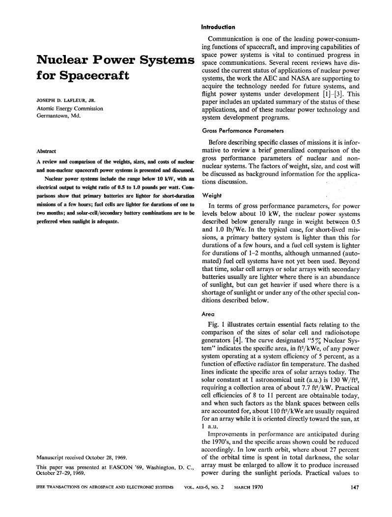
Fig. 1 illustrates certain essential facts relating to thecomparison of the sizes of solar cell and radioisotopegenerators [4]. The curve designated "5% Nuclear Sys-tem" indicates the specific area, in ft2/kWe, of any powersystem operating at a system efficiency of 5 percent, as afunction of effective radiator fin temperature. The dashedlines indicate the specific area of solar arrays today. Thesolar constant at 1 astronomical unit (a.u.) is 130 W/ft2,requiring a collection area of about 7.7 ft2/kW. Practicalcell efficiencies of 8 to 11 percent are obtainable today,and when such factors as the blank spaces between cellsare accounted for, about 110 ft2/kWe are usually requiredfor an array while it is oriented directly toward the sun, at1 a.u.Improvements in performance are anticipated during
the 1970's, and the specific areas shown could be reducedaccordingly. In low earth orbit, where about 27 percent
Manuscript received October 28, 1969. of the orbital time is spent in total darkness, the solarThis paper was presented at EASCON '69, Washington, D. C., array must be enlarged to allow it to produce increasedOctober 27-29, 1969. power during the sunlight periods. Practical values to
IEEE TRANSACTIONS ON AEROSPACE AND ELECTRONIC SYSTEMS VOL. AEs-6, NO. 2 MARCH 1970 147
Solar Cells, Unorientedla. u., Full Sun
Solar Cells, Low Earth Orbit
Solar Cells, 1 a. u full sun
4%, Th-1100OFNuclear Syste
2bO REJTON TEMP F
HEAT REJECTION TEMlP., 0 F
R2IkWe
A. U.
Fig. 1. Area of power systems, 1969.
ensure the availability of adequate power for batterycharging usually are about twice the 1 a.u. full-sunlightarea, as indicated by the middle dashed horizontal line.Day and night operation of the solar array in synchronousorbit, where there is less shadow time, results in specificareas somewhere between 110 and 200 ft2/kWeavg. Wherethe complexity of orienting the solar cells is unacceptable,an all-around array must be mounted. On an idealspherical shell an increase of a factor of 4 in area wouldresult, indicated by the dashed line at 400 ft2/kWe. Thearea would be about twice this high for low orbit, day-and-night operation.
It is shown in the following pages that the requireddimensions of solar arrays increase with distance from thesun. It is seen that the minimum solar cell arrays are
larger than isotopic system radiators, for radiator tem-peratures above about 350'F. It should be noted alsothat the nuclear radiator can assume various convenientshapes. The radiator can be wrapped around in a cylindri-cal shape, for which the frontal area is only l/7r times thetotal area.
It is also informative to examine the advisability ofincreasing radiator temperature in order to reduce radi-ator area. The "5 %' Nuclear System" curve is for a sys-
tem of the indicated heat rejection temperature. Thethermoelectric hot junction temperature would depend on
other conditions. For example, a system with a 200'Fradiator temperature might have an 800'F hot junctiontemperature; but on the right end of the curve, for the800'F radiator, the hot junction temperature obviouslywould have to be higher than 800'F. Otherwise, theCarnot efficiency would be zero and the electrical outputwould be zero.
We cannot examine the effect of increasing radiatortemperature unless we make assumptions about hot junc-tion temperatures and thermoelectric materials efficien-cies. However, we can simplify this question by examin-ing only a limited region. There are several practical gen-
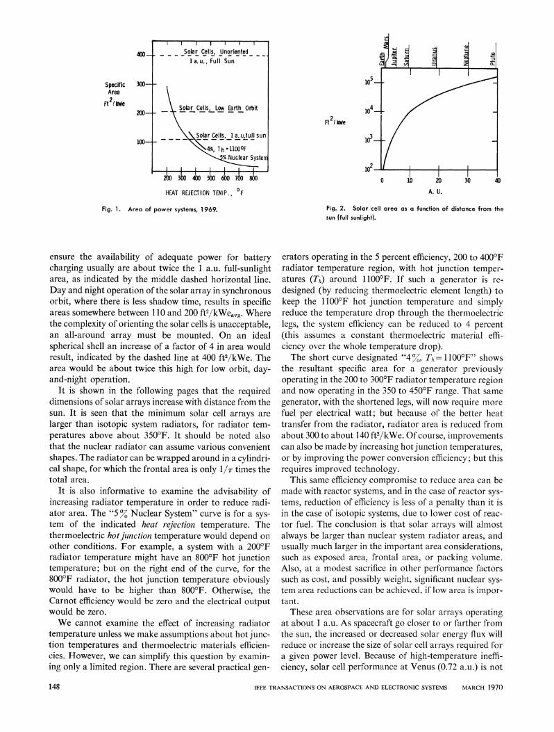
Fig. 2. Solar cell area as a function of distance from thesun (full sunlight).
erators operating in the 5 percent efficiency, 200 to 4000Fradiator temperature region, with hot junction temper-atures (Th) around 1 1000F. If such a generator is re-
designed (by reducing thermoelectric element length) tokeep the 11000F hot junction temperature and simplyreduce the temperature drop through the thermoelectriclegs, the system efficiency can be reduced to 4 percent(this assumes a constant thermoelectric material effi-ciency over the whole temperature drop).The short curve designated "4%, T, =- 11000F" shows
the resultant specific area for a generator previouslyoperating in the 200 to 300'F radiator temperature regionand now operating in the 350 to 450'F range. That same
generator, with the shortened legs, will now require more
fuel per electrical watt; but because of the better heattransfer from the radiator, radiator area is reduced fromabout 300 to about 140 ft2/kWe. Of course, improvementscan also be made by increasing hot junction temperatures,or by improving the power conversion efficiency; but thisrequires improved technology.
This same efficiency compromise to reduce area can bemade with reactor systems, and in the case of reactor sys-
tems, reduction of efficiency is less of a penalty than it isin the case of isotopic systems, due to lower cost of reac-tor fuel. The conclusion is that solar arrays will almostalways be larger than nuclear system radiator areas, andusually much larger in the important area considerations,such as exposed area, frontal area, or packing volume.Also, at a modest sacrifice in other performance factorssuch as cost, and possibly weight, significant nuclear sys-tem area reductions can be achieved, if low area is impor-tant.These area observations are for solar arrays operating
at about 1 a.u. As spacecraft go closer to or farther fromthe sun, the increased or decreased solar energy flux willreduce or increase the size of solar cell arrays required fora given power level. Because of high-temperature ineffi-ciency, solar cell performance at Venus (0.72 a.u.) is not
IEEE TRANSACTIONS ON AEROSPACE AND ELECTRONIC SYSTEMS MARCH 1970
400-
300-SpecificArea
Ft 'lWe200-
100-
148
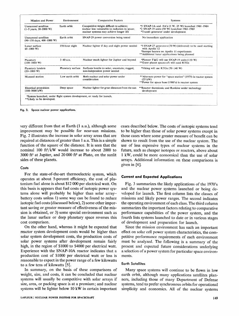
Mission and Power Environment Comparative Factors Systems
Unmanned satellites Earth orbit Competitive weight difficult to achieve; *5 SNAP-3A and -9A's (3 W, 25 W) launched 1961-1964(1-5 years, 30-2000 W) nuclear less vulnerable to radiation in space; *2 SNAP- 19 units (50 W) launched 1963-1969
nuclear systems may achieve longer life *Transit generator under development
Unmanned satellites Earth orbit SNAP-29 power conversion being tested No immediate application(90-150 days, 400-1000 W)
Lunar surface 350-hour night Nuclear lighter if day and night power needed *5 SNAP-27 generators (70 XV) (delivered) to be used starting65-1000 W) with Apollo 12
*Isotope heaters on Apollo 11 experiments**Additional lunar applications being planned
Planetary(100-1000 W)
3-40 a.u. Nuclear much lighter for Jupiter and beyond *Pioneer F&G will use SNAP-19 units (130 W)**Oater planet spacecraft will need RTGs
Planetary landers Planetary surface Surfaces hostile to solar, uncertain; rugged, *Viking will use RTGs (50-140 W)(20-1000 W) sun-independent power needed
Manned station Low earth orbit Both nuclear and solar power under **Alternate power for "space station" (1975) is reactor systemconsideration (25 kW)
**Power for space base (1980's) is reactor system
Electrical propulsion Deep space Nuclear lighter for great distances from the sun * *Reactor thermionic and Rankine under technology(100-5000 kW) development
*System launched, under flight system development, or ready for launch."*Likely to be developed.
Fig. 3. Space nuclear power applications.
very different from that at Earth (1 a.u.), although someimprovement may be possible for near-sun missions.Fig. 2 illustrates the increase in solar array areas that arerequired at distances of greater than 1 a.u. This is a simplefunction of the square of the distance. It is seen that thenominal 100 ft2/kW would increase to about 2000 to3000 ft2 at Jupiter, and 20 000 ft2 at Pluto, on the sunlitsides of these planets.
Costs
For the state-of-the-art thermoelectric system, whichoperates at about 5-percent efficiency, the cost of plu-tonium fuel alone is about $12 000 per electrical watt. Onthis basis is appears that fuel costs of isotopic power sys-tems alone will probably be higher than solar array-battery costs unless 1) some way can be found to reduceisotopic fuel costs (discussed below), 2) some other impor-tant saving or greater measure of effectiveness of the mis-sion is obtained, or 3) some special environment such asthe lunar surface or deep planetary space reverses thiscost comparison.On the other hand, whereas it might be expected that
reactor system development costs would be higher thansolar system development costs, the production costs ofsolar power systems after development remain fairlyhigh, in the region of $1000 to $4000 per electrical watt.Experience with the SNAP-10A reactor indicates that aproduction cost of $1000 per electrical watt or less isreasonable to expect in the power range of a few kilowattsto a few tens of kilowatts [5].
In summary, on the basis of these comparisons ofweight, size, and costs, it can be concluded that nuclearsystems will usually be competitive with solar arrays ifsize, area, or packing space is at a premium; and nuclearsystems will be lighter below 10 kW in certain important
cases described below. The costs of isotopic systems tendto be higher than those of solar power systems except inthose cases where some greater measure of benefit can beshown to result from the use of the nuclear system. Theuse of less expensive types of nuclear systems in thefuture, such as cheaper isotopes or reactors, above about1 kW, could be more economical than the use of solararrays. Additional information on these comparisons isgiven in [4].
Current and Expected Applications
Fig. 3 summarizes the likely applications of the 1970'sand the nuclear power systems launched or being de-veloped for launch. The first column lists the classes ofmissions and likely power ranges. The second indicatesthe operating environment of each class. The third columnsummarizes the important factors relating to comparativeperformance capabilities of the power system, and thefourth lists systems launched to date or in various stagesof development and preparation for launch.
Since the mission environment has such an importanteffect on solar cell power system characteristics, the com-petitive performance requirements of each environmentmust be analyzed. The following is a summary of thepresent and expected future considerations underlyinga selection of a power system for particular space environ-ments.
Earth Satellites
Many space systems will continue to be flown in lowearth orbit, although many applications satellites plan-ners, including those of many Department of Defensesystems, tend to prefer synchronous orbits for operationalsimplicity and economics. All of the nuclear systems
LAFLEUR: NUCLEAR POWER SYSTEMS FOR SPACECRAFT1
-1
149
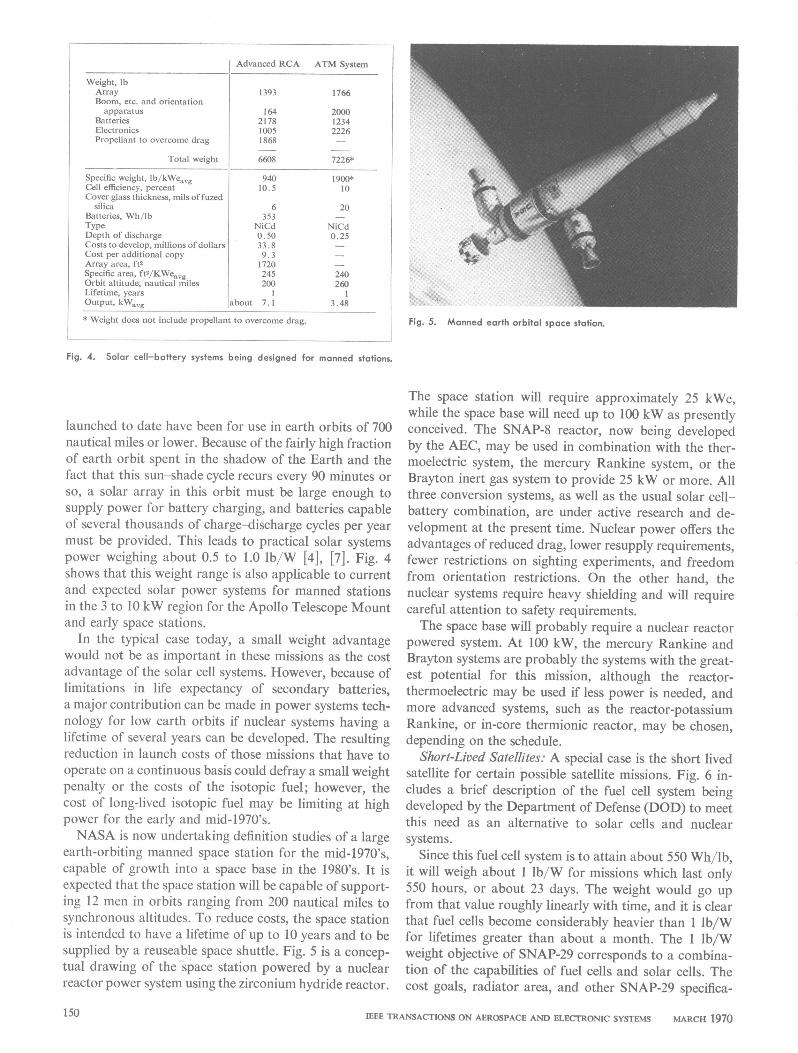
Weight, lbArrayBoom, etc. and orientationapparatus
BatteriesElectronicsPropellant to overcome drag
Total weight
Specific weight, lb/kWe,,gCell efficiency, percentCover glass thickness, mils offuzed
silicaBatteries, Wh/lbTypeDepth of dischargeCosts to develop, millions of dollarsCost per additional copyArray area, ft2Specific area, ft2/KWe,,gOrbit altitude, nautical milesLifetime, yearsO'-u tW ._
Advanced RCA ATM System
1393 1766
164 20002178 12341005 22261868 -
6608 7226*
94010.5
6353
NiCd0.5033.89.31720245200
shit71"- avg -- , l
* Weight does not include propellant to overcome drag.
1900*10
20
NiCd0.25
2402603
3.48
Fig. 5. Manned earth orbital space station.
Fig. 4. Solar cell-battery systems being designed for manned stations.
launched to date have been for use in earth orbits of 700nautical miles or lower. Because of the fairly high fractionof earth orbit spent in the shadow of the Earth and thefact that this sun-shade cycle recurs every 90 minutes orso, a solar array in this orbit must be large enough tosupply power for battery charging, and batteries capableof several thousands of charge-discharge cycles per yearmust be provided. This leads to practical solar systemspower weighing about 0.5 to 1.0 lb/W [4], [7]. Fig. 4shows that this weight range is also applicable to currentand expected solar power systems for manned stationsin the 3 to 10 kW region for the Apollo Telescope Mountand early space stations.
In the typical case today, a small weight advantagewould not be as important in these missions as the costadvantage of the solar cell systems. However, because oflimitations in life expectancy of secondary batteries,a major contribution can be made in power systems tech-nology for low earth orbits if nuclear systems having alifetime of several years can be developed. The resultingreduction in launch costs of those missions that have tooperate on a continuous basis could defray a small weightpenalty or the costs of the isotopic fuel; however, thecost of long-lived isotopic fuel may be limiting at highpower for the early and mid-1970's.NASA is now undertaking definition studies of a large
earth-orbiting manned space station for the mid-1970's,capable of growth into a space base in the 1980's. It isexpected that the space station will be capable of support-ing 12 men in orbits ranging from 200 nautical miles tosynchronous altitudes. To reduce costs, the space stationis intended to have a lifetime of up to 10 years and to besupplied by a reuseable space shuttle. Fig. 5 is a concep-tual drawing of the space station powered by a nuclearreactor power system using the zirconium hydride reactor.
The space station will require approximately 25 kWe,while the space base will need up to 100 kW as presentlyconceived. The SNAP-8 reactor, now being developedby the AEC, may be used in combination with the ther-moelectric system, the mercury Rankine system, or theBrayton inert gas system to provide 25 kW or more. Allthree conversion systems, as well as the usual solar cell-battery combination, are under active research and de-velopment at the present time. Nuclear power offers theadvantages of reduced drag, lower resupply requirements,fewer restrictions on sighting experiments, and freedomfrom orientation restrictions. On the other hand, thenuclear systems require heavy shielding and will requirecareful attention to safety requirements.The space base will probably require a nuclear reactor
powered system. At 100 kW, the mercury Rankine andBrayton systems are probably the systems with the great-est potential for this mission, although the reactor-thermoelectric may be used if less power is needed, andmore advanced systems, such as the reactor-potassiumRankine, or in-core thermionic reactor, may be chosen,depending on the schedule.
Short-Lived Satellites: A special case is the short livedsatellite for certain possible satellite missions. Fig. 6 in-cludes a brief description of the fuel cell system beingdeveloped by the Department of Defense (DOD) to meetthis need as an alternative to solar cells and nuclearsystems.
Since this fuel cell system is to attain about 550 Wh/lb,it will weigh about I lb/W for missions which last only550 hours, or about 23 days. The weight would go upfrom that value roughly linearly with time, and it is clearthat fuel cells become considerably heavier than I lb/Wfor lifetimes greater than about a month. The I lb/Wweight objective of SNAP-29 corresponds to a combina-tion of the capabilities of fuel cells and solar cells. Thecost goals, radiator area, and other SNAP-29 specifica-
IEEE TRANSACTIONS ON AEROSPACE AND ELECTRONIC SYSTEMS MARCH 1970150
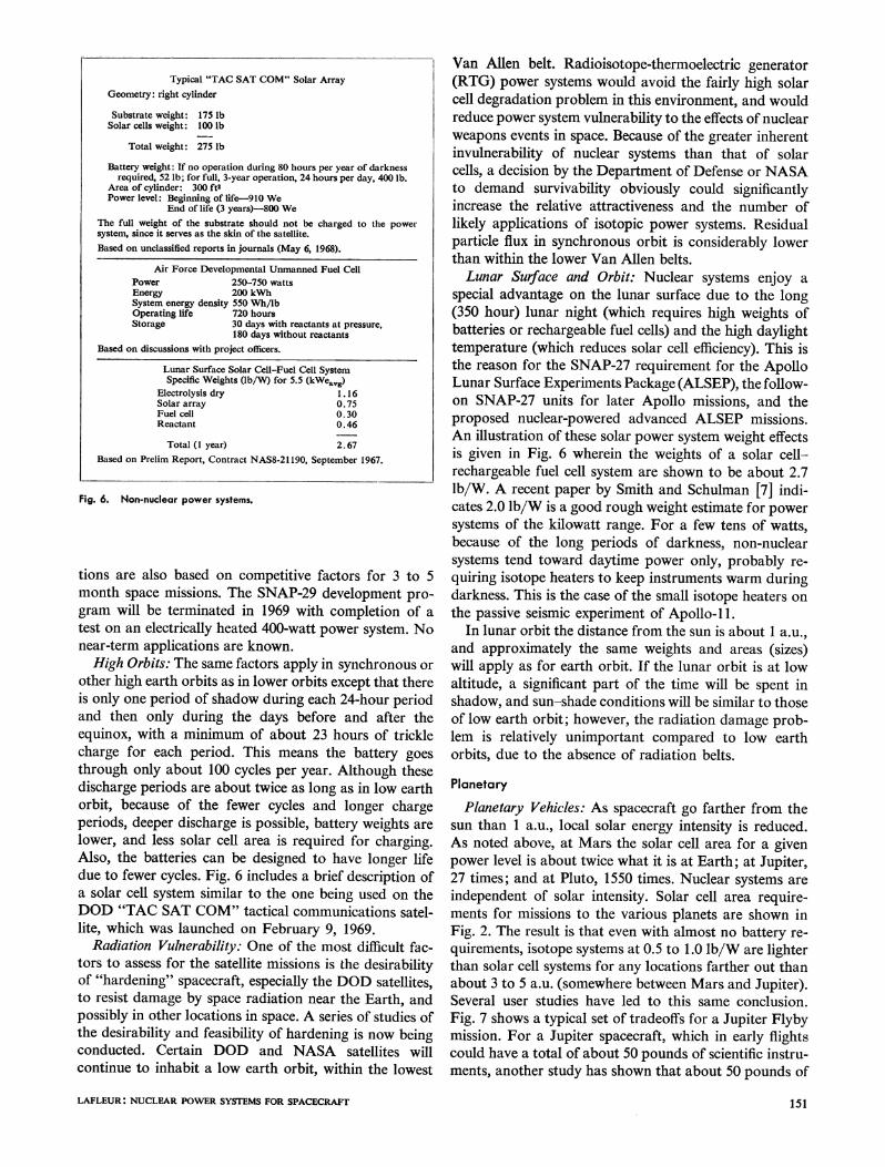
Fig. 6. Non-nuclear power systems.
tions are also based on competitive factors for 3 to 5month space missions. The SNAP-29 development pro-gram will be terminated in 1969 with completion of atest on an electrically heated 400-watt power system. Nonear-term applications are known.High Orbits: The same factors apply in synchronous or
other high earth orbits as in lower orbits except that thereis only one period of shadow during each 24-hour periodand then only during the days before and after theequinox, with a minimum of about 23 hours of tricklecharge for each period. This means the battery goesthrough only about 100 cycles per year. Although thesedischarge periods are about twice as long as in low earthorbit, because of the fewer cycles and longer chargeperiods, deeper discharge is possible, battery weights arelower, and less solar cell area is required for charging.Also, the batteries can be designed to have longer lifedue to fewer cycles. Fig. 6 includes a brief description ofa solar cell system similar to the one being used on theDOD "TAC SAT COM" tactical communications satel-lite, which was launched on February 9, 1969.
Radiation Vulnerability: One of the most difficult fac-tors to assess for the satellite missions is the desirabilityof "hardening" spacecraft, especially the DOD satellites,to resist damage by space radiation near the Earth, andpossibly in other locations in space. A series of studies ofthe desirability and feasibility of hardening is now beingconducted. Certain DOD and NASA satellites willcontinue to inhabit a low earth orbit, within the lowest
Van Allen belt. Radioisotope-thermoelectric generator(RTG) power systems would avoid the fairly high solarcell degradation problem in this environment, and wouldreduce power system vulnerability to the effects of nuclearweapons events in space. Because of the greater inherentinvulnerability of nuclear systems than that of solarcells, a decision by the Department of Defense or NASAto demand survivability obviously could significantlyincrease the relative attractiveness and the number oflikely applications of isotopic power systems. Residualparticle flux in synchronous orbit is considerably lowerthan within the lower Van Allen belts.Lunar Surface and Orbit: Nuclear systems enjoy a
special advantage on the lunar surface due to the long(350 hour) lunar night (which requires high weights ofbatteries or rechargeable fuel cells) and the high daylighttemperature (which reduces solar cell efficiency). This isthe reason for the SNAP-27 requirement for the ApolloLunar Surface Experiments Package (ALSEP), the follow-on SNAP-27 units for later Apollo missions, and theproposed nuclear-powered advanced ALSEP missions.An illustration of these solar power system weight effectsis given in Fig. 6 wherein the weights of a solar cell-rechargeable fuel cell system are shown to be about 2.7lb/W. A recent paper by Smith and Schulman [7] indi-cates 2.0 lb/W is a good rough weight estimate for powersystems of the kilowatt range. For a few tens of watts,because of the long periods of darkness, non-nuclearsystems tend toward daytime power only, probably re-
quiring isotope heaters to keep instruments warm duringdarkness. This is the case of the small isotope heaters onthe passive seismic experiment of Apollo- 11.
In lunar orbit the distance from the sun is about 1 a.u.,and approximately the same weights and areas (sizes)will apply as for earth orbit. If the lunar orbit is at lowaltitude, a significant part of the time will be spent inshadow, and sun-shade conditions will be similar to thoseof low earth orbit; however, the radiation damage prob-lem is relatively unimportant compared to low earthorbits, due to the absence of radiation belts.
Planetary
Planetary Vehicles: As spacecraft go farther from thesun than 1 a.u., local solar energy intensity is reduced.As noted above, at Mars the solar cell area for a givenpower level is about twice what it is at Earth; at Jupiter,27 times; and at Pluto, 1550 times. Nuclear systems areindependent of solar intensity. Solar cell area require-ments for missions to the various planets are shown inFig. 2. The result is that even with almost no battery re-quirements, isotope systems at 0.5 to 1.0 lb/W are lighterthan solar cell systems for any locations farther out thanabout 3 to 5 a.u. (somewhere between Mars and Jupiter).Several user studies have led to this same conclusion.Fig. 7 shows a typical set of tradeoffs for a Jupiter Flybymission. For a Jupiter spacecraft, which in early flightscould have a total of about 50 pounds of scientific instru-ments, another study has shown that about 50 pounds of
LAFLEUR: NUCLEAR POWER SYSTEMS FOR SPACECRAFT
Typical "TAC SAT COM" Solar ArrayGeometry: right cylinder
Substrate weight: 175 lbSolar cells weight: 100 lb
Total weight: 275 lb
Battery weight: If no operation during 80 hours per year of darknessrequired, 52 lb; for full, 3-year operation, 24 hours per day, 400 lb.
Area of cylinder: 300 ft2Power level: Beginning of life-910 We
End of life (3 years)-800 WeThe full weight of the substrate should not be charged to the powersystem, since it serves as the skin of the satellite.Based on unclassified reports in journals (May 6, 1968).
Air Force Developmental Unmanned Fuel CellPower 250-750 wattsEnergy 200 kWhSystem energy density 550 Wh/lbOperating life 720 hoursStorage 30 days with reactants at pressure,
180 days without reactantsBased on discussions with project officers.
Lunar Surface Solar Cell-Fuel Cell SystemSpecific Weights (lb/W) for 5.5 (kWeavg)
Electrolysis dry 1.16Solar array 0.75Fuel cell 0.30Reactant 0.46
Total (1 year) 2.67Based on Prelim Report, Contract NAS8-21190, September 1967.
151
z
Ic3:
C-)
ca:cr:44
-)0-aL 100
U:
SOLARPOWER SUPPLY
/N/P SILICONCELLS
IDEAL
SOLAR POWERXSUPPLY THINUFILM CaS
CELLSIDEAL
3YRS 5 YRSRTG+SHIELD
(INC 8%DEGRADATIONPER YEAR)
(100 WATTS ELECTRICAL OUTPUT)
O 1 2 3 4 5 6 7 8 9 10 11 12 13 14DISTANCE AU.
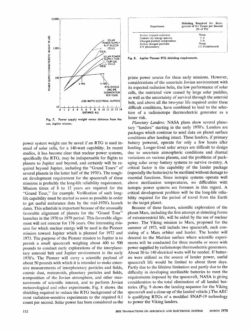
Fig. 7. Power supply weight versus distance from thesun, Jupiter mission.
power system weight can be saved if an RTG is used in-stead of solar cells, for a 140-watt capability. In recentstudies, it has become clear that nuclear power systems,specifically the RTG, may be indispensable for flights toplanets to Jupiter and beyond, and certainly will be re-quired beyond Jupiter, including the "Grand Tours" ofseveral planets in the latter half of the 1970's. The tough-est development requirement for the spacecraft of thesemissions is probably the long-life reliability requirement.Mission times of 8 to 12 years are required for the"Grand Tour," for example. Verification of such long-life capability must be started as soon as possible in orderto get useful endurance data by the mid-1970's launchdates. This schedule is important because of the unusuallyfavorable alignment of planets for the "Grand Tour"launches in the 1976 to 1979 period. This favorable align-ment will not reoccur for 176 years. One interesting mis-sion for which nuclear energy will be used is the Pioneermission toward Jupiter which is planned for 1972 and1973. The purpose of the Pioneer mission to Jupiter is topermit a small spacecraft weighing about 400 to 500pounds to conduct early explorations of the interplane-tary asteroid belt and Jupiter environment in the early1970's. The Pioneer will carry a scientific payload ofabout 50 pounds with which it is intended to make exten-sive measurements of interplanetary particles and fields,cosmic dust, meteoroids, planetary particles and fields,composition of the Jovian atmosphere, and other mea-surements of scientific interest, and to perform Jovianmeteorological and other experiments. Fig. 8 shows theshielding required to reduce the RTG background of themost radiation-sensitive experiments to the required 0.1count per second. Solar power has been considered as the
Experiment
Jovian trapped radiationCosmic ray energy spectraCharged particle compositionJovian charged particlesUV photometry
Shielding Required for Back-ground of 0.1 Count per Second
(lb of Pb)
None1.43.0None<3 0 (estimated)
Fig. 8. Jupiter Pioneer RTG shielding requirements.
prime power source for these early missions. However,considerations of the uncertain Jovian environment withits expected radiation belts, the low performance of solarcells, the restricted view caused by large solar paddles,as well as the uncertainty of survival through the asteroidbelt, and above all the two-year life required under thesedifficult conditions, have combined to lead to the selec-tion of a radioisotope thermoelectric generator as alesser risk.
Planetary Landers: NASA plans show several plane-tary "landers" starting in the early 1970's. Landers arepackages which continue to send data on planet surfaceconditions after landing intact. These landers, if primarybattery powered, operate for only a few hours afterlanding. Longer-lived solar arrays are difficult to designdue to uncertain atmospheric conditions and diurnalvariations on various planets, and the problems of pack-aging solar array-battery systems to survive re-entry. Acritical factor is the capability of the lander package(especially the batteries) to be sterilized without damage toessential functions. Since isotopic systems operate wellabove sterilization temperatures, no difficulties withisotopic power systems are foreseen in this regard. Acritical development problem will be the long-life relia-bility required for the period of travel from the Earthto the target planet.
Because of these factors, scientific exploration of theplanet Mars, including the first attempt at detecting formsof extraterrestrial life, will be aided by the use of nuclearpower. The Viking mission to Mars, proposed for thesummer of 1973, will include two spacecraft, each con-sisting of a Mars orbiter and lander. The lander willdescend to the Martian surface where scientific experi-ments will be conducted for three months or more withpower supplied by radioisotope thermoelectric generators.About 50 to 140 electrical watts will be needed. If batter-ies were utilized as the source of lander power, usefulspacecraft life would be limited to about three days.Partly due to the lifetime limitation and partly due to thedifficulty in developing sterilizable batteries to meet therequirements imposed by the spacecraft, NASA is givingconsideration to the total elimination of all landed bat-teries. (Fig. 9 shows the landing sequence for the Vikingspacecraft and a close-up of the landed vehicle.) The AECis qualifying RTGs of a modified SNAP-19 technologyto power the Viking landers.
IEEE TRANSACTIONS ON AEROSPACE AND ELECTRONIC SYSTEMS MARCH 1970
AU .M0
152
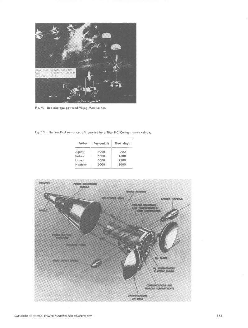
Fig. 9. Radioisotope-powered Viking Mars lander.
Fig. 1O. Nuclear Rankine spacecraft, boosted by a Titan IIIC/Centaur launch vehicle.
Probes Payload, lb Time, days
Jupiter 7000 700Saturn 6000 1 600Uranus 5000 2200Neptune 5000 3000
LAFLEUR: NUCLEAR POWER SYSTEMS FOR SPACECRAFT 153
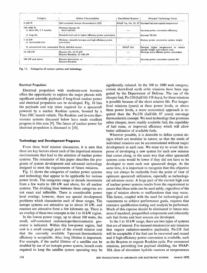
Category0-00W
100-1000 Wa) short life, 2-5 months
b) long life
1-10 kWa) recoverable fuel
b) unrecovered fuel, unmar
10-100 kW
100 kW and above
mned
System Characteristics
ISelf-contained isotope thermoelectric (TE)
IModular isotope-TEshort half-life
Reusable fuel and or higher efficiency power conversion
Modular, resuable isotopes and high-efficiency powerconversion
Partly shielded reactor
Reactor-TE, 10-25 kWReactor-Rankine, 25-100 kW
Reactor-thermionic, orReactor-Rankine
Established Systemss Principal Technology Goals
Y7 T----o.-vand --A.f- at-Q 4- -.-........INrtAP aiA, 9A ,9 / Increase tuel and capsule temperature
SN,
Increase power conversi
Increase TE life
Reduce power conversi
AP lOA |Develop higher tempspecific weight and radi
- Develop more efficient 1
- Increase power conversi
ion efficiency
ion system weight
erature to reduceiator areapower conversion
ion system life
Fig. 11. Categories of nuclear systems and technology.
Electrical Propulsion
Electrical propulsion with moderate-cost boostersoffers the opportunity to explore the major planets withsignificant scientific payloads if long-lived nuclear powerand electrical propulsion can be developed. Fig. 10 liststhe payloads and trip times required for a spacecraftpowered by a nuclear Rankine system, boosted by aTitan IIIC launch vehicle. The Rankine and in-core ther-mionics systems discussed below have made excellentprogress in this area [9]. The future of nuclear power forelectrical propulsion is discussed in [10].
Technology and Development Programs
From these brief mission discussions, it is seen thatthere are key factors about each of the important missionenvironments that lead to the selection of nuclear powersystems. The remainder of this paper describes the pro-grams of system development and advanced technologydesigned to meet the requirements of future missions.
Fig. 11 shows the categories of nuclear power systemsand technology that appear to be applicable for variouspower levels. The categories range in decade incrementsfrom a few watts to 100 kW and above, for all nuclearsystems. The dividing lines between these categories arenot exact and inflexible. There is considerable powerlevel overlap; however, there are special developmentproblems which characterize each of these ranges. Theisotope systems are attractive up to about 10 kW, andreactors are attractive from a few kilowatts up. There isan overlap of these two concepts in the 1 to 10 kW region.
In the lowest power range, up to about 100 watts, thesmall, self-contained radioisotope-thermoelectric gen-erator is indicated. Within this low-power region, fuelcost is a small enough part of the overall mission costthat the currently available 5-percent thermoelectricefficiency is acceptable. Also, long lifetime is important.For example, if the useful lifetime of a satellite can bedoubled by use of an isotopic power system, launch costsrequired to keep the satellite system operating may be
significantly reduced. In the 100 to 1000 watt category,certain short-lived earth orbit missions have been sug-gested by the Department of Defense. The use of thecheaper fuel, Po-210 (half-life 138 days), for these missionsis possible because of the short mission life. For longer-lived missions (years) at these power levels, or abovethese power levels, a more economical approach is re-quired than the Pu-238 (half-life 87 years) one-stagethermoelectric concept. We need technology that promiseseither cheaper, more readily available fuel, the capabilityof fuel reuse, or improved efficiency which will allowbetter utilization of available fuels.Wherever possible, it is desirable to define system de-
signs which are modular in nature, so that the needs ofindividual missions can be accommodated without majordevelopment in each case. We must try to avoid the ex-pense of developing a new system for each new missionthat comes along, in the same way that other spacecraftsystems costs would be lower if they did not have to bedeveloped to meet each new spacecraft design. At thesame time, it is important to recognize that this objectivemay not always be realizable from the point of view ofoptimum spacecraft utilization, especially as technologi-cal advances occur. A large part of the current high costof nuclear power systems results from the requirement toassure that these units can be used safely, regardless of thetype of mission aborts or malfunctions that may occur.This factor, coupled with the need for technological ad-vancements to achieve performance goals, requires thatextensive qualification testing and analysis be performed.Much of this expense should be eliminated in future mis-sions if standard, prequalified components and inherentlysafe fuel forms and heat sources are developed.
In the 1 to 10 kW range, there are two types of systemsthat are of interest. For manned missions (or any missionsthat require radiation-sensitive payloads), Pu-238 fuelwill be acceptable if the fuel can be recovered and reusedand if high-efficiency power conversion is available, suchas the Brayton or organic Rankine cycle. For unmannedmissions, permitting low payload shielding, the SNAP-lOA class of zirconium hydride reactors at temperatures
IEEE TRANSACTIONS ON AEROSPACE AND ELECTRONIC SYSTEMS MARCH 1970
CQM AD I A O A 1G0
,I
. ] . Al,. __~~~~~~~~~~~~~~~~~~~~~~~~~~~~~~~~~~~~~~~~~~~~~~~~~~~~~~~~~~~~~~~~~~~~~~~~~~~~~~~~~~~~~~~~~~~~~~~~~~~~~~~~~~~~~~~._..
-.7
154
(A) (B)Itr In{
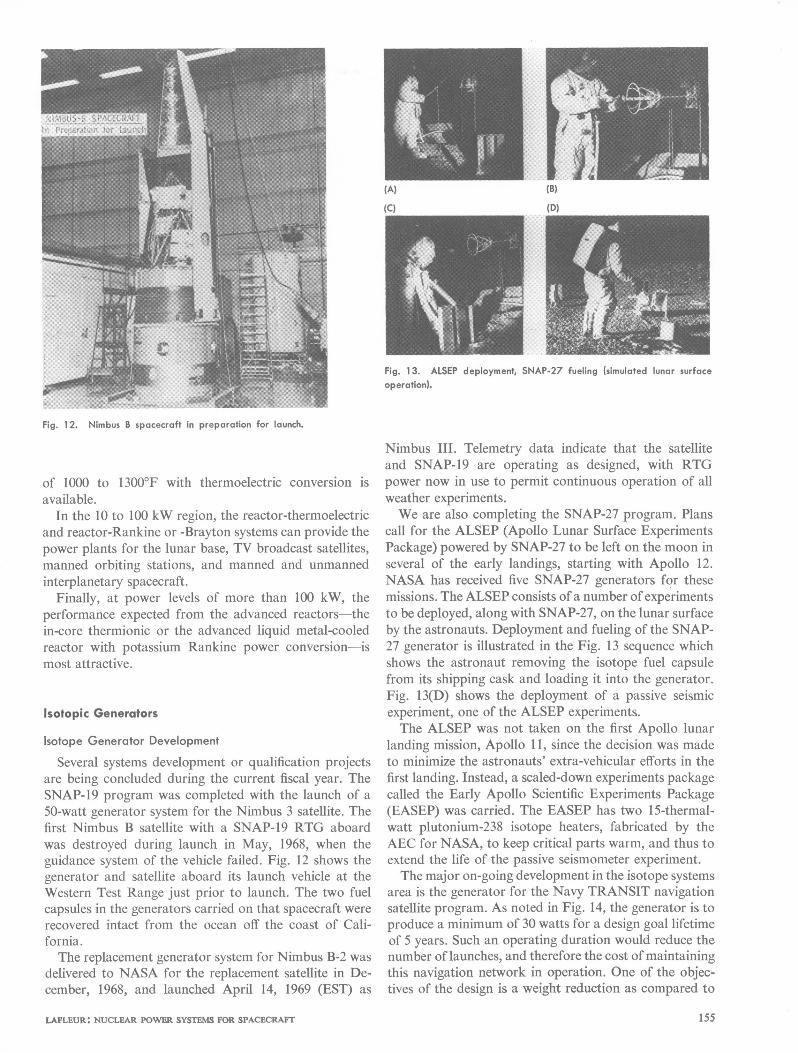
Fig. 13. ALSEP deployment, SNAP-27 fueling (simulated lunar surfaceoperation).
Fig. 12. Nimbus B spacecraft in preparation for launch.
of 1000 to 1300'F with thermoelectric conversion isavailable.
In the 10 to 100 kW region, the reactor-thermoelectricand reactor-Rankine or -Brayton systems can provide thepower plants for the lunar base, TV broadcast satellites,manned orbiting stations, and manned and unmannedinterplanetary spacecraft.
Finally, at power levels of more than 100 kW, theperformance expected from the advanced reactors-thein-core thermionic or the advanced liquid metal-cooledreactor with potassium Rankine power conversion-ismost attractive.
Isotopic Generators
Isotope Generator Development
Several systems development or qualification projectsare being concluded during the current fiscal year. TheSNAP-19 program was completed with the launch of a50-watt generator system for the Nimbus 3 satellite. Thefirst Nimbus B satellite with a SNAP-19 RTG aboardwas destroyed during launch in May, 1968, when theguidance system of the vehicle failed. Fig. 12 shows thegenerator and satellite aboard its launch vehicle at theWestern Test Range just prior to launch. The two fuelcapsules in the generators carried on that spacecraft wererecovered intact from the ocean off the coast of Cali-fornia.The replacement generator system for Nimbus B-2 was
delivered to NASA for the replacement satellite in De-cember, 1968, and launched April 14, 1969 (EST) as
Nimbus III. Telemetry data indicate that the satelliteand SNAP-19 are operating as designed, with RTGpower now in use to permit continuous operation of allweather experiments.We are also completing the SNAP-27 program. Plans
call for the ALSEP (Apollo Lunar Surface ExperimentsPackage) powered by SNAP-27 to be left on the moon inseveral of the early landings, starting with Apollo 12.NASA has received five SNAP-27 generators for thesemissions. The ALSEP consists of a number ofexperimentsto be deployed, along with SNAP-27, on the lunar surfaceby the astronauts. Deployment and fueling of the SNAP-27 generator is illustrated in the Fig. 13 sequence whichshows the astronaut removing the isotope fuel capsulefrom its shipping cask and loading it into the generator.Fig. 13(D) shows the deployment of a passive seismicexperiment, one of the ALSEP experiments.The ALSEP was not taken on the first Apollo lunar
landing mission, Apollo 11, since the decision was madeto minimize the astronauts' extra-vehicular efforts in thefirst landing. Instead, a scaled-down experiments packagecalled the Early Apollo Scientific Experiments Package(EASEP) was carried. The EASEP has two 15-thermal-watt plutonium-238 isotope heaters, fabricated by theAEC for NASA, to keep critical parts warm, and thus toextend the life of the passive seismometer experiment.The major on-going development in the isotope systems
area is the generator for the Navy TRANSIT navigationsatellite program. As noted in Fig. 14, the generator is toproduce a minimum of 30 watts for a design goal lifetimeof 5 years. Such an operating duration would reduce thenumber of launches, and therefore the cost of maintainingthis navigation network in operation. One of the objec-tives of the design is a weight reduction as compared to
LAFLEUR: NUCLEAR POWER SYSTEMS FOR SPACECRAFT 155
Application Modified Navy transit satellitePower, in electrical watts, at end of life 30Weight, lb 15 (objective)Lifetime, years 5
Fig. 14. NAVSAT (TRANSIT) generator characteristics.
Fig. 15. Long-life isotope generator technology; importance of hightemperature.
I
t
,E
15
10
0.8
0.7,
I
0.6 St
0.5
0.4
8 TRE TR12 HO0 JNTO TEMRAE0OFTHERMOELECTRIC HOT JUNCTION4 TEMPERATUJRE, OF
0.I
I
0.8 id
-06
- 0.0
earlier generators, aimed at approaching a 15-poundsystem weight. This program is planned as a two-phaseeffort. Design selection will be made within a few days,as a result of a study recently completed. This study willbe followed by the hardware development phase, whichwill include the deliveries to the Navy of several electri-cally and nuclear-heated generators. All available tech-nology is being considered to arrive at the design conceptto be followed. A 5-year lifetime with relatively stableoutput is a tough goal to meet. None of the latest high-performing components have been under test for fiveyears; it therefore is necessary to extrapolate shorter-term data in order to predict 5-year performance.
Isotope Generator Technology
Aside from the flight system projects, the isotope gen-
erator work is directed toward meeting the technologicalrequirements of long-life isotope generators. This workis essential if we are to provide for the needs of the futureand avoid the costs of undertaking a specific productdevelopment to meet a schedule when there is inadequatetechnology and lead-time base. The major need is forwork which stresses long-life fuels, capsules, and power
conversion technology.Fig. 15 illustrates the importance of high-temperature
capability in reducing fuel investment, weight, and radia-tor area. Fifty-percent reductions are possible in each ofthese important factors if we are able to increase the hot-side operating temperature of thermoelectrics from thepresent level of 800 to 1100F to the 2000'F temperatureat which we are testing our advanced fuel forms, fuelcapsules, and high-temperature thermoelectrics.
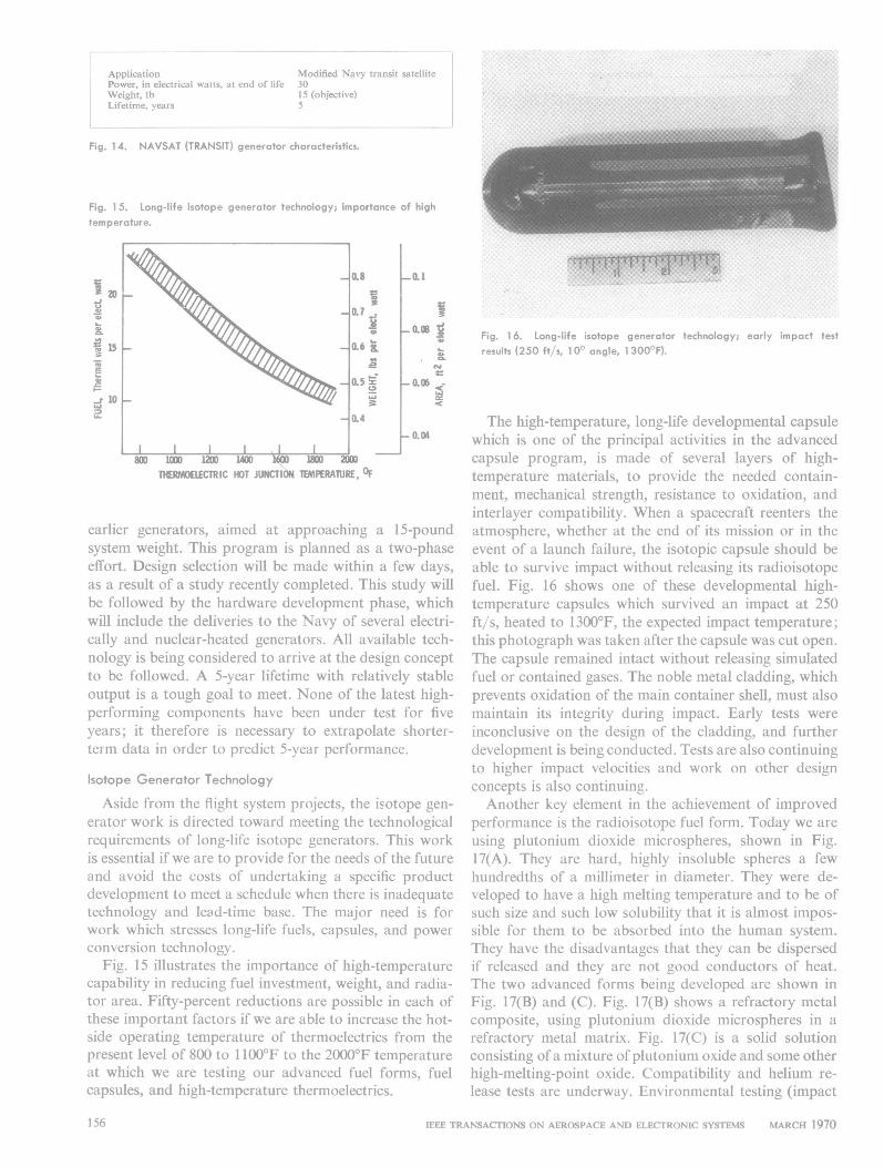
Fig. 16. Long-life isotope generator technology; early impact test
results (250 ft/s, 100 angle, 1 300'F).
The high-temperature, long-life developmental capsulewhich is one of the principal activities in the advancedcapsule program, is made of several layers of high-temperature materials, to provide the needed contain-ment, mechanical strength, resistance to oxidation, andinterlayer compatibility. When a spacecraft reenters theatmosphere, whether at the end of its mission or in theevent of a launch failure, the isotopic capsule should beable to survive impact without releasing its radioisotopefuel. Fig. 16 shows one of these developmental high-temperature capsules which survived an impact at 250ft/s, heated to 1300'F, the expected impact temperature;this photograph was taken after the capsule was cut open.
The capsule remained intact without releasing simulatedfuel or contained gases. The noble metal cladding, whichprevents oxidation of the main container shell, must alsomaintain its integrity during impact. Early tests were
inconclusive on the design of the cladding, and furtherdevelopment is being conducted. Tests are also continuingto higher impact velocities and work on other designconcepts is also continuing.Another key element in the achievement of improved
performance is the radioisotope fuel form. Today we are
using plutonium dioxide microspheres, shown in Fig.17(A). They are hard, highly insoluble spheres a fewhundredths of a millimeter in diameter. They were de-veloped to have a high melting temperature and to be ofsuch size and such low solubility that it is almost impos-sible for them to be absorbed into the human system.They have the disadvantages that they can be dispersedif released and they are not good conductors of heat.The two advanced forms being developed are shown inFig. 17(B) and (C). Fig. 17(B) shows a refractory metalcomposite, using plutonium dioxide microspheres in a
refractory metal matrix. Fig. 17(C) is a solid solutionconsisting of a mixture ofplutonium oxide and some otherhigh-melting-point oxide. Compatibility and helium re-
lease tests are underway. Environmental testing (impact
IEEE TRANSACTIONS ON AEROSPACE AND ELECTRONIC SYSTEMS MARCH 1970
I II I I. I
156
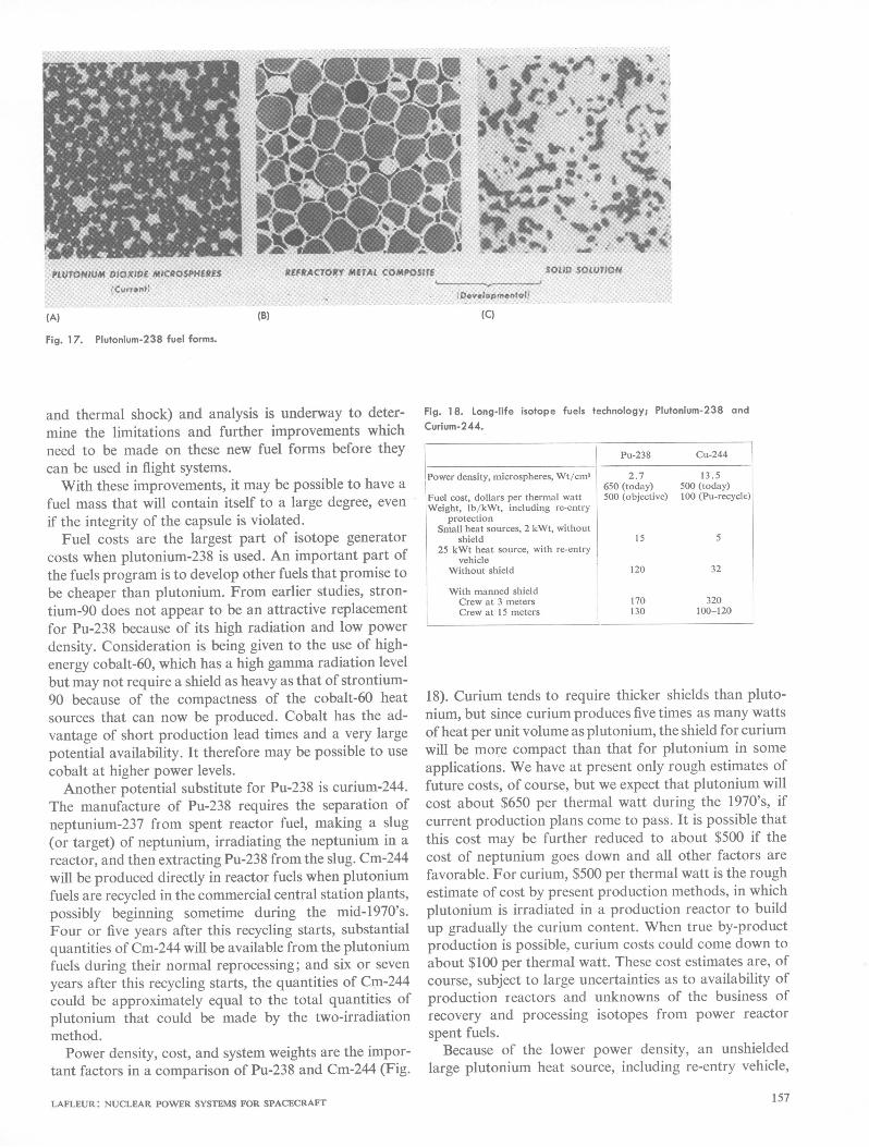
(A) (B) (C)
Fig. 17. Plutonium-238 fuel forms.
and thermal shock) and analysis is underway to deter-mine the limitations and further improvements whichneed to be made on these new fuel forms before theycan be used in flight systems.With these improvements, it may be possible to have a
fuel mass that will contain itself to a large degree, evenif the integrity of the capsule is violated.
Fuel costs are the largest part of isotope generatorcosts when plutonium-238 is used. An important part ofthe fuels program is to develop other fuels that promise tobe cheaper than plutonium. From earlier studies, stron-tium-90 does not appear to be an attractive replacementfor Pu-238 because of its high radiation and low powerdensity. Consideration is being given to the use of high-energy cobalt-60, which has a high gamma radiation levelbut may not require a shield as heavy as that of strontium-90 because of the compactness of the cobalt-60 heatsources that can now be produced. Cobalt has the ad-vantage of short production lead times and a very largepotential availability. It therefore may be possible to usecobalt at higher power levels.Another potential substitute for Pu-238 is curium-244.
The manufacture of Pu-238 requires the separation ofneptunium-237 from spent reactor fuel, making a slug(or target) of neptunium, irradiating the neptunium in areactor, and then extracting Pu-238 from the slug. Cm-244will be produced directly in reactor fuels when plutoniumfuels are recycled in the commercial central station plants,possibly beginning sometime during the mid-1970's.Four or five years after this recycling starts, substantialquantities of Cm-244 will be available from the plutoniumfuels during their normal reprocessing; and six or sevenyears after this recycling starts, the quantities of Cm-244could be approximately equal to the total quantities ofplutonium that could be made by the two-irradiationmethod.Power density, cost, and system weights are the impor-
tant factors in a comparison of Pu-238 and Cm-244 (Fig.
LAFLEUR: NUCLEAR POWER SYSTEMS FOR SPACECRAFT
Fig. 18. Long-life isotope fuels technology; Plutonium-238 andCurium-244.
Pu-238
Power density. microspheres, Wt/cm3 2.7650 (today)
Fuel cost. dollars per thermal watt 500 (objective)
protectionSmall heat sources, 2 kWt, without
shield 1525 kWt heat source, with re-entry
vehicleWithout shield 120
With manned shieldCrew at 3 metersCrew at 15 meters
170130
Cu-244
13.5500 (today)100 (Pu-recycle)
5
32
320100-120
18). Curium tends to require thicker shields than pluto-nium, but since curium produces five times as many wattsof heat per unit volume as plutonium, the shield for curiumwill be more compact than that for plutonium in someapplications. We have at present only rough estimates offuture costs, of course, but we expect that plutonium willcost about $650 per thermal watt during the 1970's, ifcurrent production plans come to pass. It is possible thatthis cost may be further reduced to about $500 if thecost of neptunium goes down and all other factors arefavorable. For curium, $500 per thermal watt is the roughestimate of cost by present production methods, in whichplutonium is irradiated in a production reactor to buildup gradually the curium content. When true by-productproduction is possible, curium costs could come down toabout $100 per thermal watt. These cost estimates are, ofcourse, subject to large uncertainties as to availability ofproduction reactors and unknowns of the business ofrecovery and processing isotopes from power reactorspent fuels.
Because of the lower power density, an unshieldedlarge plutonium heat source, including re-entry vehicle,
157
HEAT SOURCE AND
SAFETY STUDIES
HIGH-TEMPERATURE FUEL
AND CAPSULE TECHNOLOGY
HEAT SOURCE
CAPSULE FABRICATION
BRAYTON CYCLEGROUND TEST
9 FY1970 F
NA
|ADONI
f SOUR(
STARTPLUAIRNOOK
A COMPONENT
HEATDISIGN
isis
TESTS
DLIOVEEIMLEE CAPSULE
ISOTOPEFUELED TEST
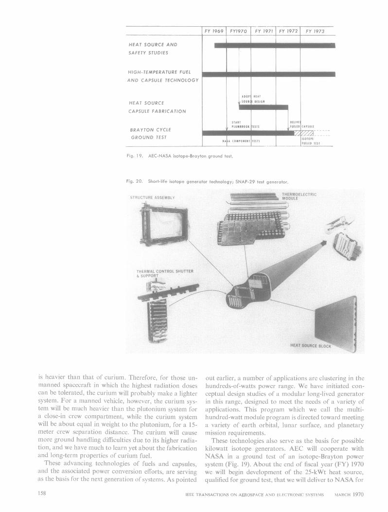
Fig. 19. AEC-NASA isotope-Brayton ground test,
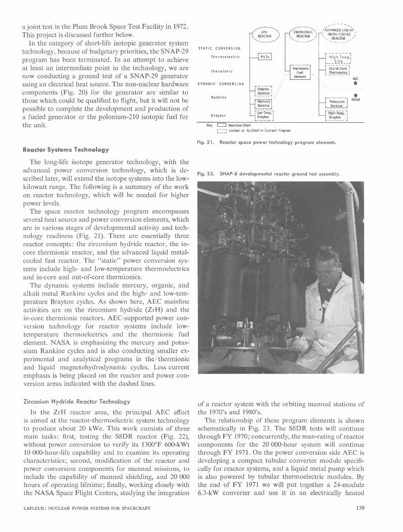
Fig. 20. Short-life isotope generator technology; SNAP-29 test generator.
I01~~t1
is heavier than that of curium. Therefore, for those un-manned spacecraft in which the highest radiation dosescan be tolerated, the curium will probably make a lightersystem. For a manned vehicle, however, the curium sys-tem will be much heavier than the plutonium system fora close-in crew compartment, while the curium systemwill be about equal in weight to the plutonium, for a 15-meter crew separation distance. The curium will causemore ground handling difficulties due to its higher radia-tion, and we have much to learn yet about the fabricationand long-term properties of curium fuel.These advancing technologies of fuels and capsules,
and the associated power conversion efforts, are servingas the basis for the next generation of systems. As pointed
out earlier, a number of applications are clustering in thehundreds-of-watts power range. We have initiated con-ceptual design studies of a modular long-lived generatorin this range, designed to meet the needs of a variety ofapplications. This program which we call the multi-hundred-watt module program is directed toward meetinga variety of earth orbital, lunar surface, and planetarymission requirements.These technologies also serve as the basis for possible
kilowatt isotope generators. AEC will cooperate withNASA in a ground test of an isotope-Brayton powersystem (Fig. 19). About the end of fiscal year (FY) 1970we will begin development of the 25-kWt heat source,qualified for ground test, that we will deliver to NASA for
IEEE TRANSACTIONS ON AEROSPACE AND ELECTRONIC SYSTEMS MARCH 1970
FY 1969 _~ __E FY 1972 FY 1973
-IIl l _
l _ Milll _
.1Il l_E ,/7/2_
158
a joint test in the Plum Brook Space Test Facility in 1972.This project is discussed further below.
In the category of short-life isotopic generator systemtechnology, because of budgetary priorities, the SNAP-29program has been terminated. In an attempt to achieveat least an intermediate point in the technology, we arenow conducting a ground test of a SNAP-29 generatorusing an electrical heat source. The non-nuclear hardwarecomponents (Fig. 20) for the generator are similar tothose which could be qualified to flight, but it will not bepossible to complete the development and production ofa fueled generator or the polonium-210 isotopic fuel forthe unit.
Reactor Systems Technology
The long-life isotope generator technology, with theadvanced power conversion technology, which is de-scribed later, will extend the isotope systems into the low-kilowatt range. The following is a summary of the workon reactor technology, which will be needed for higherpower levels.The space reactor technology program encompasses
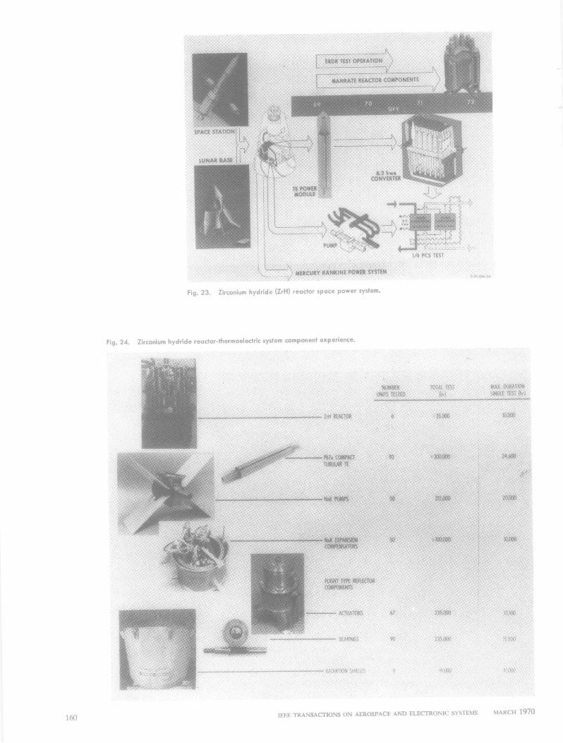
several heat source and power conversion elements, whichare in various stages of developmental activity and tech-nology readiness (Fig. 21). There are essentially threereactor concepts: the zirconium hydride reactor, the in-core thermionic reactor, and the advanced liquid metal-cooled fast reactor. The "static" power conversion sys-tems include high- and low-temperature thermoelectricsand in-core and out-of-core thermionics.The dynamic systems include mercury, organic, and
alkali metal Rankine cycles and the high- and low-tem-perature Brayton cycles. As shown here, AEC mainlineactivities are on the zirconium hydride (ZrH) and thein-core thermionic reactors. AEC-supported power con-version technology for reactor systems include low-temperature thermoelectrics and the thermionic fuelelement. NASA is emphasizing the mercury and potas-sium Rankine cycles and is also conducting smaller ex-perimental and analytical programs in the! thermionicand liquid magnetohydrodynamic cycles. Less currentemphasis is being placed on the reactor and power con-version areas indicated with the dashed lines.
Zirconium Hydride Reactor Technology
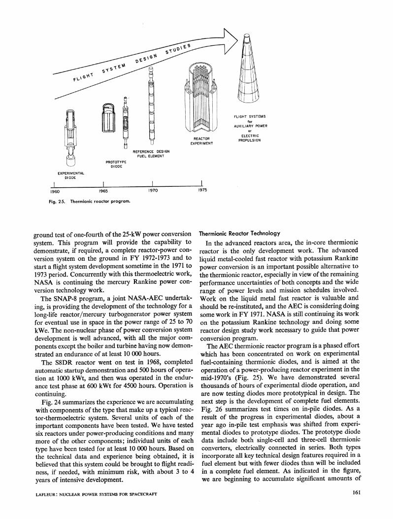
In the ZrH reactor area, the principal AEC effortis aimed at the reactor-thermoelectric system technologyto produce about 20 kWe. This work consists of threemain tasks: first, testing the S8DR reactor (Fig. 22),without power conversion to verify its 13000F 600-kWt10 000-hour-life capability and to examine its operatingcharacteristics; second, modification of the reactor andpower conversion components for manned missions, toinclude the capability of manned shielding, and 20 000hours of operating lifetime; finally, working closely withthe NASA Space Flight Centers, studying the integration
STATIC CONVERSION
Therm oo lectr it
Thermionic
DYNAMIC CONVERSION
Rankine
Brayton
Zrll
,,__L _1__--IntM~ lo,
REACTOR
Thrmni
- OianicRankine
.O__;_ _
riow-Ternp2rayton
------- -.'ADVANCED LIQUID'.- METAL-COOLED
I REACTOR -'
I - - - I
_ High Temp.:
- - --- --__ Out--Core
* Thermlnnics,AE
r H,:gh-Teest.Brayton
ANASA
Key = Mainline EffortLimited or No Effort in Current Program
Fig. 21. Reactor space power technology program elements.
Fig. 22. SNAP-8 developmental reactor ground test assembly.
of a reactor system with the orbiting manned stations ofthe 1970's and 1980's.The relationship of these program elements is shown
schematically in Fig. 23. The S8DR tests will continuethrough FY 1970; concurrently, the man-rating of reactorcomponents for the 20 000-hour system will continuethrough FY 1971. On the power conversion side AEC isdeveloping a compact tubular converter module specifi-cally for reactor systems, and a liquid metal pump whichis also powered by tubular thermoelectric modules. Bythe end of FY 1971 we will put together a 24-module6.3-kW converter and use it in an electrically heated
LAFLEUR: NUCLEAR POWER SYSTEMS FOR SPACECRAFrT 159
Ift, ,
23 Zicnui reMaCUto spacNEpower SYSTEm.
Fig. 23. Zirconium hydride (ZrH) reactor space power system.
Fig. 24. Zirconium hydride reactor-thermoelectric system component experience.
IEEE TRANSACTIONS ON AEROSPACE AND ELECTRONIC SYSTEMS MARCH 197016(0
U
PROTOTYPEDIODE
EXPERIMENTALDIODE
1960 1965
-MS
)WER
REACTOREXPERI MENT
REFERENCE DESIGNFUEL ELEMENT
197011975
Fig. 25. Thermionic reactor program.
ground test of one-fourth of the 25-kW power conversionsystem. This program will provide the capability todemonstrate, if required, a complete reactor-power con-version system on the ground in FY 1972-1973 and tostart a flight system development sometime in the 1971 to1973 period. Concurrently with this thermoelectric work,NASA is continuing the mercury Rankine power con-version technology work.The SNAP-8 program, a joint NASA-AEC undertak-
ing, is providing the development of the technology for along-life reactor/mercury turbogenerator power systemfor eventual use in space in the power range of 25 to 70kWe. The non-nuclear phase of power conversion systemdevelopment is well advanced, with all the major com-ponents except the boiler and turbine having now demon-strated an endurance of at least 10 000 hours.The S8DR reactor went on test in 1968, completed
automatic startup demonstration and 500 hours of opera-tion at 1000 kWt, and then was operated in the endur-ance test phase at 600 kWt for 4500 hours. Operation iscontinuing.
Fig. 24 summarizes the experience we are accumulatingwith components of the type that make up a typical reac-tor-thermoelectric system. Several units of each of theimportant components have been tested. We have testedsix reactors under power-producing conditions and manymore of the other components; individual units of eachtype have been tested for at least 10 000 hours. Based onthe technical data and experience being obtained, it isbelieved that this system could be brought to flight readi-ness, if needed, with minimum risk, with about 3 to 4years of intensive development.
LAFLEUR: NUCLEAR POWER SYSTEMS FOR SPACECRAFT
Thermionic Reactor TechnologyIn the advanced reactors area, the in-core thermionic
reactor is the only development work. The advancedliquid metal-cooled fast reactor with potassium Rankinepower conversion is an important possible alternative tothe thermionic reactor, especially in view of the remainingperformance uncertainties of both concepts and the widerange of power levels and mission schedules involved.Work on the liquid metal fast reactor is valuable andshould be re-instituted, and the AEC is considering doingsome work in FY 1971. NASA is still continuing its workon the potassium Rankine technology and doing somereactor design study work necessary to guide that powerconversion program.The AEC thermionic reactor program is a phased effort
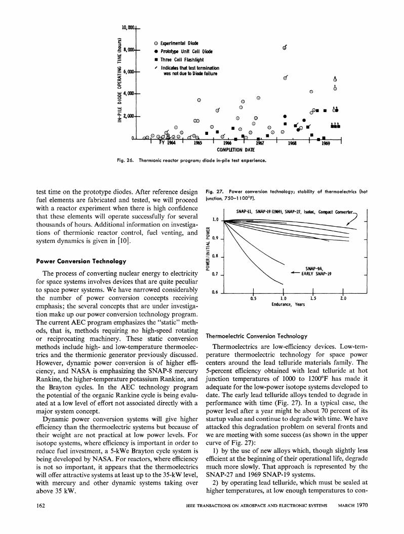
which has been concentrated on work on experimentalfuel-containing thermionic diodes, and is aimed at theoperation of a power-producing reactor experiment in themid-1970's (Fig. 25). We have demonstrated severalthousands of hours of experimental diode operation, andare now testing diodes more prototypical in design. Thenext step is the development of complete fuel elements.Fig. 26 summarizes test times on in-pile diodes. As aresult of the progress in experimental diodes, about ayear ago in-pile test emphasis was shifted from experi-mental diodes to prototype diodes. The prototype diodedata include both single-cell and three-cell thermionicconverters, electrically connected in series. Both typesincorporate all key technical design features required in afuel element but with fewer diodes than will be includedin a complete fuel element. As indicated in the figure,we are beginning to accumulate significant amounts of
161
I'
0 Experimental Diode* Prototype Unit Cell Diode* Three Cell Flashlight- Indicates that test termination
was not due to Diode failure
0
I FY 1964 1 1965
El
0
00
0
d md. _0 0
C *OUE.a E. 0U(Er 0-~
0U
0D00
aU' 1T96
COMPLETION DARE
0
U(1
1968 ' 1969 1
Fig. 26. Thermionic reactor program; diode in-pile test experience.
test time on the prototype diodes. After reference designfuel elements are fabricated and tested, we will proceedwith a reactor experiment when there is high confidencethat these elements will operate successfully for severalthousands of hours. Additional information on investiga-tions of thermionic reactor control, fuel venting, andsystem dynamics is given in [10].
Power Conversion Technology
The process of converting nuclear energy to electricityfor space systems involves devices that are quite peculiarto space power systems. We have narrowed considerablythe number of power conversion concepts receivingemphasis; the several concepts that are under investiga-tion make up our power conversion technology program.
The current AEC program emphasizes the "static" meth-ods, that is, methods requiring no high-speed rotatingor reciprocating machinery. These static conversionmethods include high- and low-temperature thermoelec-trics and the thermionic generator previously discussed.However, dynamic power conversion is of higher effi-ciency, and NASA is emphasizing the SNAP-8 mercury
Rankine, the higher-temperature potassium Rankine, andthe Brayton cycles. In the AEC technology programthe potential of the organic Rankine cycle is being evalu-ated at a low level of effort not associated directly with a
major system concept.Dynamic power conversion systems will give higher
efficiency than the thermoelectric systems but because oftheir weight are not practical at low power levels. Forisotope systems, where efficiency is important in order toreduce fuel investment, a 5-kWe Brayton cycle system isbeing developed by NASA. For reactors, where efficiencyis not so important, it appears that the thermoelectricswill offer attractive systems at least up to the 35-kW level,with mercury and other dynamic systems taking over
above 35 kW.
Fig. 27. Power conversion technology; stability of thermoelectrics (hotjunction, 750-1 1 000F).
1.0
z0.8
0
0.7
0.6
Endurance, Years
Thermoelectric Conversion Technology
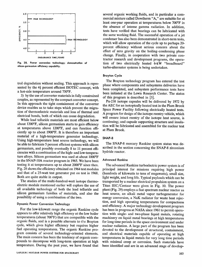
Thermoelectrics are low-efficiency devices. Low-tem-perature thermoelectric technology for space powercenters around the lead telluride materials family. The5-percent efficiency obtained with lead telluride at hotjunction temperatures of 1000 to 1200'F has made itadequate for the low-power isotope systems developed todate. The early lead telluride alloys tended to degrade inperformance with time (Fig. 27). In a typical case, thepower level after a year might be about 70 percent of itsstartup value and continue to degrade with time. We haveattacked this degradation problem on several fronts andwe are meeting with some success (as shown in the uppercurve of Fig. 27):
1) by the use of new alloys which, though slightly lessefficient at the beginning of their operational life, degrademuch more slowly. That approach is represented by theSNAP-27 and 1969 SNAP-19 systems.
2) by operating lead telluride, which must be sealed athigher temperatures, at low enough temperatures to con-
IEEE TRANSACTIONS ON AEROSPACE AND ELECTRONIC SYSTEMS MARCH 1970
r
_ 8,000.
2 6,000-
0
0
c. 2,000-z 2
n
46
0noP (.dOlo G I
v - 1,31:1 1 - - 1- %ZA I - . = L-i me I I - = Il~~~~~~~- M- llO,WOj-
-
-
162
6.0
5.5
Et
z
M.
5.0
4.5
4.0
1 2 3 4
ENDURANCE TIME,YEARS
5
CHNOLOGY
Fig. 28. Power conversion technology; demonstration ofsilicon-germanium efficiency capability.
trol degradation without sealing. This approach is repre-sented by the 4' percent efficient ISOTEC concept, witha hot-side temperature around 750'F.
3) by the use of converter materials in fully constrainedcouples, as represented by the compact converter concept.In this approach the tight containment of the converterdevice enables us to take steps which prevent the migra-tion of thermoelectric materials and loss of thermal andelectrical bonds, both of which can cause degradation.While lead telluride materials are most efficient below
about 1200'F, silicon germanium starts to gain efficiencyat temperatures above 1200'F, and can function effi-ciently up to about 1900'F. It is therefore an importantmaterial of a high-temperature generator technology.Using high-temperature heat source technology, we willbe able to fabricate 5 percent efficient systems with silicongermanium, and possibly eventually 8 to 11 percent effi-ciencies with a combination of the high- and low-tempera-ture alloys. Silicon germanium was used at about 10000Fin the SNAP-IOA reactor program in 1965. We have beentesting it at temperatures up to about 2000'F since then.Fig. 28 shows the efficiency obtained on 1964 test modulesand that of a 25-watt test generator put on test in 1968.Both are quite stable in output.The studies of the multi-hundred-watt isotope thermo-
electric module mentioned earlier will explore the use ofall available technology of both the lead telluride andsilicon germanium families of materials, and also thepossibility of using a combination of the two.
Dynamic Power Conversion TechnologyFor the low-kilowatt range the organic Rankine cycle
appears to offer relatively high efficiency at the low boilertemperatures (about 700'F) that are compatible with theorganic fluids, and is a possible alternate to the Braytoncycle, which gives higher efficiency but requires higherfuel operating temperatures. The organic Rankine pro-gram consists of several technology-oriented elements.The main concern has been the tendency of organic com-pounds to decompose with long-term operation at hightemperature. During the past year, we have found that
several organic working fluids, and in particular a com-mercial mixture called Dowtherm "A," are suitable for atleast one-year operation at temperatures below 700'F inthe absence of intense gamma radiation. In addition,tests have verified that bearings can be lubricated withthe same working fluid. The successful operation of a jetcondenser has also been demonstrated in short-term tests,which will allow operation of the cycle up to perhaps 20-percent efficiency without serious concern about theeffect of zero gravity on the boiling-condensing phasechange. Finally, in cooperation with two private con-tractor research and development programs, the opera-tion of two electrically heated 6-kW "breadboard"turbo-alternator systems is being undertaken.
Brayton CycleThe Brayton technology program has entered the test
phase where components and subsystems deliveries havebeen completed, and subsystem performance tests havebeen initiated at the Lewis Research Center. The statusof this program is described in [3].
Pu-238 isotope capsules will be delivered by 1972 bythe AEC for an isotopically heated test in the Plum BrookSpace Power Facility following electrically heated tests.A program for design of the isotope reentry vehicle, whichwill ensure intact reentry of the isotope heat source, iscontinuing; and capsule supporting structure and insula-tion will be fabricated and assembled for the nuclear testat Plum Brook.
SNAP-8The SNAP-8 mercury Rankine system status was de-
scribed in the section concerning the SNAP-8 zirconiumhydride reactor.
Advanced Rankine
The advanced Rankine turboelectric power system is ofprincipal interest for missions requiring high power(hundreds of kilowatts to tens of megawatts), small size,light weight, and long life. Typical payloads which can betransported by a nuclear electrical propulsion system on aTitan IIIC/Centaur were given in Fig. 10. The powerplant (Fig. 29) employs a fast spectrum nuclear reactor asheat source, an alkali metal vapor turbogenerator forenergy conversion, a NaK radiator for waste heat rejec-tion, and high operating temperatures for compactnessand efficiency. A major technology development programhas been in progress at NASA since 1961 to permit opera-tion with single- and two-phase liquid metals, rotatingmachinery on liquid metal bearings at high temperaturesfor long time periods in the space environment and undernuclear radiation. A large part of the program has beendevoted to the development of structural, containment,and electrical materials capable of operating at hightemperatures in liquid metals for very long time periodswith minimal creep or corrosion. Such materials havebeen identified and are in an advanced stage of develop-
LAFLEUR: NUCLEAR POWER SYSTEMS FOR SPACECRAFT 163
1968 TECHNOLOGY
I 1964 TE4
I I 1' I 1.
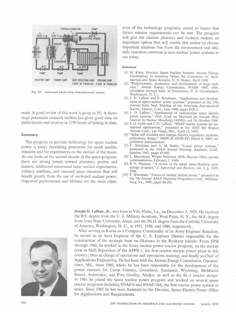
Fig. 29. Advanced alkali-metal turboalternator system.
ment. A good review of this work is given in [9]. A three-stage potassium research turbine has given good data onperformance and erosion in 1350 hours of testing to date.
Summary
The program to provide technology for space nuclearpower is today furnishing generators for earth satellitemissions and for experiments on the surface of the moon.As one looks at the second decade of the space program,there are strong trends toward planetary probes andlanders, additional automated lunar surface experiments,military satellites, and manned space missions that willbenefit greatly from the use of on-board nuclear power.Improved performance and lifetime are the main objec-
tives of the technology programs, aimed to insure thatfuture mission requirements can be met. The programwill give the mission planners and decision makers animportant option that will enable this nation to chooseimportant missions free from the environment and atti-tude restraints common in non-nuclear power systems inuse today.
References
[1] M. Klein, Director, Space Nuclear Systems, Atomic EnergyCommission, in testimony before the Committee on Aero-nautical and Space Sciences, U. S. Senate, April 1969.
[2] "Radioisotopes, production and development of large scaleuses," Atomic Energy Commission, WASH 1095, 1968.(Available through Supt. of Documents, U. S. Government,Washington, D. C.)
[3] J. D. Lafleur and F. Schulman, "Applications and develop-ment of space nuclear power systems," presented at the 15thAnnual Joint Natil. Meeting of the American AstronauticalSociety, Denver, Colo., June 1969, paper IXE-3.
[4] J. D. Lafleur, "Applications of radioisotope space electricpower systems," Proc. Conf. on Materials for Isotopic HeatSources, in Nuclear Metallurgy (AIME), vol. 14, October 1968.
[5] J. D. Gylfe and J. D. Lafleur, "SNAP reactor systems for un-manned applications," presented at the IEEE 6th RegionAnnual Conf., Las Vegas, Nev., April 13, 1965.
[6] "Solar cell modules and charges/battery/regulatory modules,preliminary design," MSFC-R-ASTR-EP, March 6, 1967, un-published memorandum.
[7] F. Schulman and A. H. Smith, "Lunar power systems,"presented at the AIAA Annual Meeting, Anaheim, Calif.,October 1967, paper 67-902.
[8] L. Harootyan, Wright Patterson AFB, Dayton, Ohio, privatecommunication, February 3, 1969.
[9] S. V. Manson, "A review of the alkali metal Rankine tech-nology program," J. Spacecraft and Rockets, vol. 5, p. 1249,1968.
[10] F. Schulman, "Future of nuclear electric power," presented atthe 7th Annual AIAA Electrical Propulsion Conf., Williams-burg, Va., 1969, paper 69-291.
Joseph D. Lafleur, Jr., was born in Ville Platte, La., on December 3, 1929. He receivedthe B.S. degree from the U. S. Military Academy, West Point, N. Y., the M.S. degreefrom Iowa State University, Ames, and the Ph.D. degree from the Catholic Universityof America, Washington, D. C., in 1951, 1956, and 1960, respectively.
After serving in Korea as a Company Commander of an Army Engineer Battalion,he served as an Area Engineer of the U. S. Engineer District responsible for theconstruction of the strategic base on Okinawa in the Ryukyus Islands. From 1956through 1960, he worked in the Army nuclear power reactor program, on the startupcrew as Shift Supervisor of the APPR-1, the first reactor electric power plant in thiscountry; then in charge of operations and operations training; and finally as Chief ofApplications Engineering. He has been with the Atomic Energy Commission, German-town, Md., since 1960, where he has been responsible for the development of thepower reactors for Camp Century, Greenland; Sundance, Wyoming; McMurdoSound, Antarctica; and Fort Greeley, Alaska; as well as the SL-2 reactor design.In 1961 he joined the space nuclear power program and worked on several spacereactor programs including SNAP-8 and SNAP-10A, the first reactor power system inspace. Since 1965 he has been Assistant to the Director, Space Electric Power Officefor Applications and Requirements.
IEEE TRANSACTIONS ON AEROSPACE AND ELECTRONIC SYSTEMS MARCH 1970164