Embed Size (px)
Citation preview
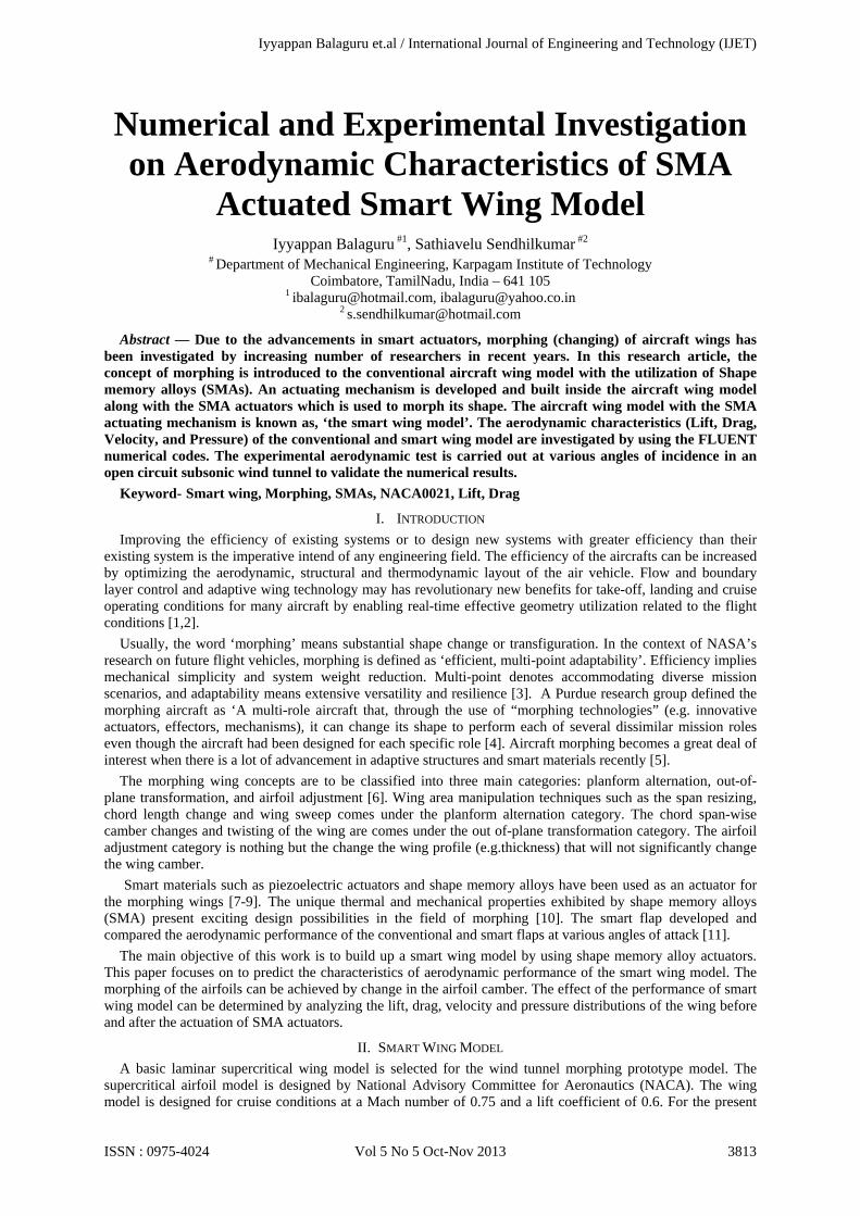
Numerical and Experimental Investigation on Aerodynamic Characteristics of SMA
Actuated Smart Wing Model Iyyappan Balaguru #1, Sathiavelu Sendhilkumar #2
# Department of Mechanical Engineering, Karpagam Institute of Technology Coimbatore, TamilNadu, India – 641 105
1 [email protected], [email protected] 2 [email protected]
Abstract — Due to the advancements in smart actuators, morphing (changing) of aircraft wings has been investigated by increasing number of researchers in recent years. In this research article, the concept of morphing is introduced to the conventional aircraft wing model with the utilization of Shape memory alloys (SMAs). An actuating mechanism is developed and built inside the aircraft wing model along with the SMA actuators which is used to morph its shape. The aircraft wing model with the SMA actuating mechanism is known as, ‘the smart wing model’. The aerodynamic characteristics (Lift, Drag, Velocity, and Pressure) of the conventional and smart wing model are investigated by using the FLUENT numerical codes. The experimental aerodynamic test is carried out at various angles of incidence in an open circuit subsonic wind tunnel to validate the numerical results.
Keyword- Smart wing, Morphing, SMAs, NACA0021, Lift, Drag
I. INTRODUCTION Improving the efficiency of existing systems or to design new systems with greater efficiency than their
existing system is the imperative intend of any engineering field. The efficiency of the aircrafts can be increased by optimizing the aerodynamic, structural and thermodynamic layout of the air vehicle. Flow and boundary layer control and adaptive wing technology may has revolutionary new benefits for take-off, landing and cruise operating conditions for many aircraft by enabling real-time effective geometry utilization related to the flight conditions [1,2].
Usually, the word ‘morphing’ means substantial shape change or transfiguration. In the context of NASA’s research on future flight vehicles, morphing is defined as ‘efficient, multi-point adaptability’. Efficiency implies mechanical simplicity and system weight reduction. Multi-point denotes accommodating diverse mission scenarios, and adaptability means extensive versatility and resilience [3]. A Purdue research group defined the morphing aircraft as ‘A multi-role aircraft that, through the use of “morphing technologies” (e.g. innovative actuators, effectors, mechanisms), it can change its shape to perform each of several dissimilar mission roles even though the aircraft had been designed for each specific role [4]. Aircraft morphing becomes a great deal of interest when there is a lot of advancement in adaptive structures and smart materials recently [5].
The morphing wing concepts are to be classified into three main categories: planform alternation, out-of-plane transformation, and airfoil adjustment [6]. Wing area manipulation techniques such as the span resizing, chord length change and wing sweep comes under the planform alternation category. The chord span-wise camber changes and twisting of the wing are comes under the out of-plane transformation category. The airfoil adjustment category is nothing but the change the wing profile (e.g.thickness) that will not significantly change the wing camber.
Smart materials such as piezoelectric actuators and shape memory alloys have been used as an actuator for the morphing wings [7-9]. The unique thermal and mechanical properties exhibited by shape memory alloys (SMA) present exciting design possibilities in the field of morphing [10]. The smart flap developed and compared the aerodynamic performance of the conventional and smart flaps at various angles of attack [11].
The main objective of this work is to build up a smart wing model by using shape memory alloy actuators. This paper focuses on to predict the characteristics of aerodynamic performance of the smart wing model. The morphing of the airfoils can be achieved by change in the airfoil camber. The effect of the performance of smart wing model can be determined by analyzing the lift, drag, velocity and pressure distributions of the wing before and after the actuation of SMA actuators.
II. SMART WING MODEL A basic laminar supercritical wing model is selected for the wind tunnel morphing prototype model. The
supercritical airfoil model is designed by National Advisory Committee for Aeronautics (NACA). The wing model is designed for cruise conditions at a Mach number of 0.75 and a lift coefficient of 0.6. For the present
Iyyappan Balaguru et.al / International Journal of Engineering and Technology (IJET)
ISSN : 0975-4024 Vol 5 No 5 Oct-Nov 2013 3813
work, the model is tested at an off-design Mach number 0.3. For these flow conditions, the wing is equipped with a morphing upper surface skin and it could be optimized during flight to lower the drag by promoting an extended laminar flow region. The airfoil section of the basic wing model is the NACA 0021. The wing had a chord length of 160 mm and a span of 310 mm. A. Construction
The wing model consists of two main parts: a flexible part, which is subjected to deformation, and a rigid part supporting the actuation system. The rigid part is made of aluminium sheet metal. After a thorough design investigation the wing flexible skin part is manufactured with a woven fabric skin. Mounted on the rigid part, the flexible skin was attached rigidly at 1% chord below the wing leading edge, covering the upper surface of the wing. The actuation line is attached to the wing at 25.3% chord. The flexible skin deformation is ensured by SMA wire. The SMA wire contractions and expansions, depending on the temperature, are translated into a vertical displacement of up to 8 mm at the actuation point. The SMA actuators are driven to deform the flexible wing skin into an optimal shape for a given flow condition under aerodynamic pressure loads.
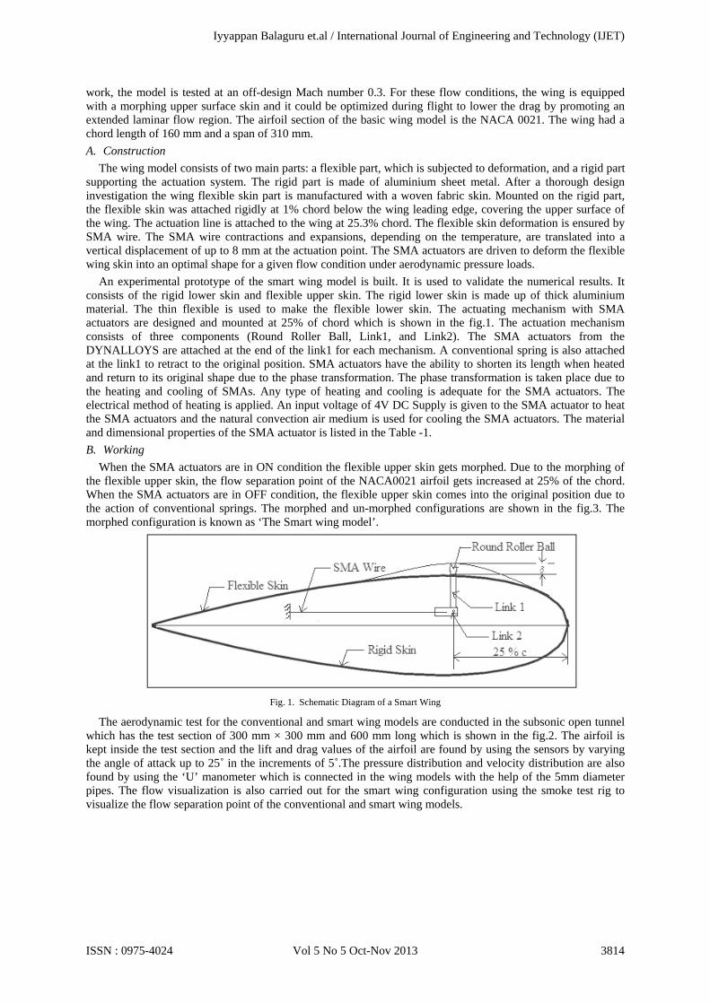
An experimental prototype of the smart wing model is built. It is used to validate the numerical results. It consists of the rigid lower skin and flexible upper skin. The rigid lower skin is made up of thick aluminium material. The thin flexible is used to make the flexible lower skin. The actuating mechanism with SMA actuators are designed and mounted at 25% of chord which is shown in the fig.1. The actuation mechanism consists of three components (Round Roller Ball, Link1, and Link2). The SMA actuators from the DYNALLOYS are attached at the end of the link1 for each mechanism. A conventional spring is also attached at the link1 to retract to the original position. SMA actuators have the ability to shorten its length when heated and return to its original shape due to the phase transformation. The phase transformation is taken place due to the heating and cooling of SMAs. Any type of heating and cooling is adequate for the SMA actuators. The electrical method of heating is applied. An input voltage of 4V DC Supply is given to the SMA actuator to heat the SMA actuators and the natural convection air medium is used for cooling the SMA actuators. The material and dimensional properties of the SMA actuator is listed in the Table -1. B. Working
When the SMA actuators are in ON condition the flexible upper skin gets morphed. Due to the morphing of the flexible upper skin, the flow separation point of the NACA0021 airfoil gets increased at 25% of the chord. When the SMA actuators are in OFF condition, the flexible upper skin comes into the original position due to the action of conventional springs. The morphed and un-morphed configurations are shown in the fig.3. The morphed configuration is known as ‘The Smart wing model’.
Fig. 1. Schematic Diagram of a Smart Wing
The aerodynamic test for the conventional and smart wing models are conducted in the subsonic open tunnel which has the test section of 300 mm × 300 mm and 600 mm long which is shown in the fig.2. The airfoil is kept inside the test section and the lift and drag values of the airfoil are found by using the sensors by varying the angle of attack up to 25˚ in the increments of 5˚.The pressure distribution and velocity distribution are also found by using the ‘U’ manometer which is connected in the wing models with the help of the 5mm diameter pipes. The flow visualization is also carried out for the smart wing configuration using the smoke test rig to visualize the flow separation point of the conventional and smart wing models.
Iyyappan Balaguru et.al / International Journal of Engineering and Technology (IJET)
ISSN : 0975-4024 Vol 5 No 5 Oct-Nov 2013 3814
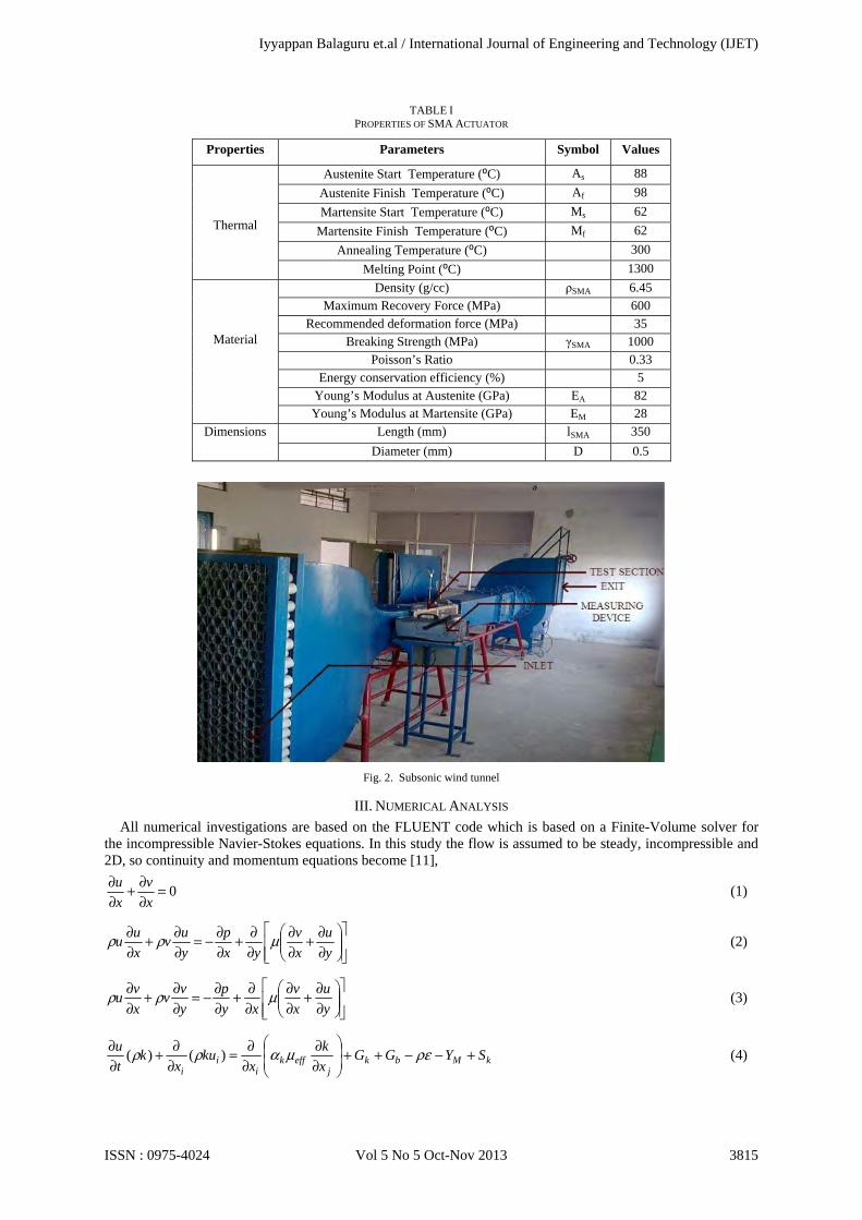
TABLE I PROPERTIES OF SMA ACTUATOR
Properties Parameters Symbol Values
Thermal
Austenite Start Temperature (⁰C) As 88 Austenite Finish Temperature (⁰C) Af 98 Martensite Start Temperature (⁰C) Ms 62
Martensite Finish Temperature (⁰C) Mf 62 Annealing Temperature (⁰C) 300
Melting Point (⁰C) 1300
Material
Density (g/cc) ρSMA 6.45 Maximum Recovery Force (MPa) 600
Recommended deformation force (MPa) 35 Breaking Strength (MPa) γSMA 1000
Poisson’s Ratio 0.33 Energy conservation efficiency (%) 5
Young’s Modulus at Austenite (GPa) EA 82 Young’s Modulus at Martensite (GPa) EM 28
Dimensions Length (mm) lSMA 350 Diameter (mm) D 0.5
Fig. 2. Subsonic wind tunnel
III. NUMERICAL ANALYSIS All numerical investigations are based on the FLUENT code which is based on a Finite-Volume solver for
the incompressible Navier-Stokes equations. In this study the flow is assumed to be steady, incompressible and 2D, so continuity and momentum equations become [11],
0=∂∂+
∂∂
x
v
x
u (1)
∂∂+
∂∂
∂∂+
∂∂−=
∂∂+
∂∂
y
u
x
v
yx
p
y
uv
x
uu μρρ (2)
∂∂+
∂∂
∂∂+
∂∂−=
∂∂+
∂∂
y
u
x
v
xy
p
y
vv
x
vu μρρ (3)
kMbkj
effki
ii
SYGGx
k
xku
xk
t
u +−−++
∂∂
∂∂=
∂∂+
∂∂ ρεμαρρ )()(
(4)
Iyyappan Balaguru et.al / International Journal of Engineering and Technology (IJET)
ISSN : 0975-4024 Vol 5 No 5 Oct-Nov 2013 3815
εεεεεε
ερεεμαρερε SRk
CGCGk
Cxx
uxt bk
jeff
ii
i
+−−++
∂∂
∂∂=
∂∂+
∂∂ 2
231 )()()(
(5)
In equations (1) to (5), ‘Gk’ denotes the generation of turbulence kinetic energy due to the mean velocity gradients, ‘Gb’ is the generation of turbulence kinetic energy due to buoyancy, ‘YM’ denotes the contribution of the fluctuating dilatation in compressible turbulence to the overall dissipation rate. The quantities αk and αε are the inverse effective Prandtl numbers for k and ε , respectively. ‘Sk’ and ‘Sε’ are user-defined source terms.’C1ε’, ‘C2ε’, and ‘C3ε’ are constant.
]1015.02843.03516.012605.02969.0[5 432 ξξξξξ −+−−±= ctyt (6) 21019.1 ctrt = (7)
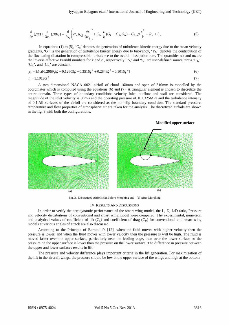
A two dimensional NACA 0021 airfoil of chord 160mm and span of 310mm is modelled by the coordinates which is computed using the equations (6) and (7). A triangular element is chosen to discretize the entire domain. Three types of boundary conditions velocity inlet, outflow and wall are considered. The magnitude of the inlet velocity is 50m/s and the operating pressure of 101.325MPa and the turbulence intensity of 0.1.All surfaces of the airfoil are considered as the non-slip boundary condition. The standard pressure, temperature and flow properties of atmospheric air are taken for the analysis. The discretized airfoils are shown in the fig. 3 with both the configurations.
Fig. 3. Discretized Airfoils (a) Before Morphing and (b) After Morphing
IV. RESULTS AND DISCUSSIONS In order to verify the aerodynamic performance of the smart wing model, the L, D, L/D ratio, Pressure
and velocity distributions of conventional and smart wing model were compared. The experimental, numerical and analytical values of coefficient of lift (CL) and coefficient of drag (CD) for conventional and smart wing models at various angles of attack are also discussed.
According to the Principle of Bernoulli’s [12], when the fluid moves with higher velocity then the pressure is lower, and when the fluid moves with lower velocity then the pressure is will be high. The fluid is moved faster over the upper surface, particularly near the leading edge, than over the lower surface so the pressure on the upper surface is lower than the pressure on the lower surface. The difference in pressure between the upper and lower surfaces results in lift.
The pressure and velocity difference plays important criteria in the lift generation. For maximization of the lift in the aircraft wings, the pressure should be low at the upper surface of the wings and high at the bottom
(a)
(b)
Modified upper surface
Iyyappan Balaguru et.al / International Journal of Engineering and Technology (IJET)
ISSN : 0975-4024 Vol 5 No 5 Oct-Nov 2013 3816
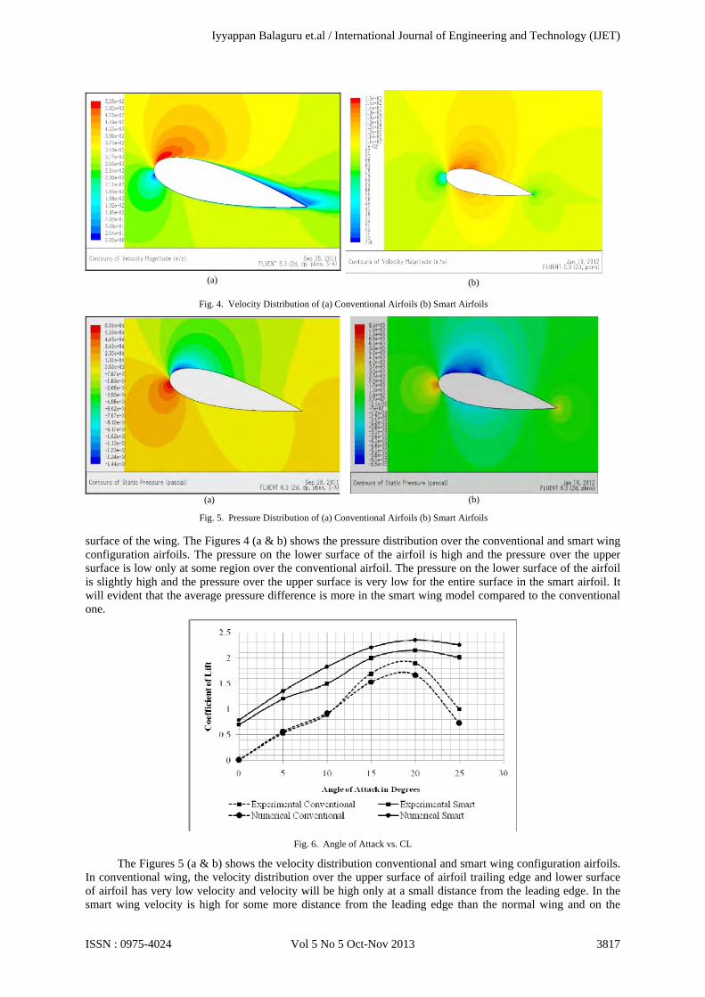
surface of the wing. The Figures 4 (a & b) shows the pressure distribution over the conventional and smart wing configuration airfoils. The pressure on the lower surface of the airfoil is high and the pressure over the upper surface is low only at some region over the conventional airfoil. The pressure on the lower surface of the airfoil is slightly high and the pressure over the upper surface is very low for the entire surface in the smart airfoil. It will evident that the average pressure difference is more in the smart wing model compared to the conventional one.
Fig. 6. Angle of Attack vs. CL
The Figures 5 (a & b) shows the velocity distribution conventional and smart wing configuration airfoils. In conventional wing, the velocity distribution over the upper surface of airfoil trailing edge and lower surface of airfoil has very low velocity and velocity will be high only at a small distance from the leading edge. In the smart wing velocity is high for some more distance from the leading edge than the normal wing and on the
(a)
(b)
Fig. 4. Velocity Distribution of (a) Conventional Airfoils (b) Smart Airfoils
(a)
(b)
Fig. 5. Pressure Distribution of (a) Conventional Airfoils (b) Smart Airfoils
Iyyappan Balaguru et.al / International Journal of Engineering and Technology (IJET)
ISSN : 0975-4024 Vol 5 No 5 Oct-Nov 2013 3817
lower surface of the airfoil the velocity is slightly higher than the conventional wing.
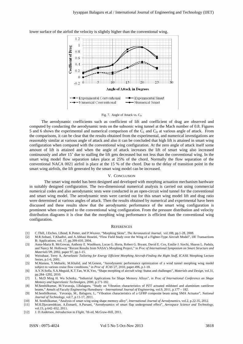
Fig. 7. Angle of Attack vs. CD
The aerodynamic coefficients such as coefficient of lift and coefficient of drag are observed and computed by conducting the aerodynamic tests on the subsonic wing tunnel at the Mach number of 0.8. Figures 5 and 6 shows the experimental and numerical comparison of the CL and CD at various angle of attack. From the comparisons, it can be clear that the results obtained from the experimental, and numerical investigations are reasonably similar at various angle of attack and also it can be concluded that high lift is attained in smart wing configuration when compared with the conventional wing configuration. At the zero angle of attack itself some amount of lift is attained and when the angle of attack increases the lift of smart wing also increased continuously and after 15˚ due to stalling the lift gets decreased but not less than the conventional wing. In the smart wing model flow separation takes place at 25% of the chord. Normally the flow separation of the conventional NACA 0021 airfoil is place at the 15 % of the chord. Due to the delay of transition point in the smart wing airfoils, the lift generated by the smart wing model can be increased.
V. CONCLUSION The smart wing model has been designed and developed with morphing actuation mechanism hardware
in suitably designed configuration. The two-dimensional numerical analysis is carried out using commercial numerical codes and also aerodynamic tests were conducted in an open-circuit wind tunnel for the conventional and smart wing model. The aerodynamic tests were carried out for this smart wing model lift and drag ratio were determined at various angles of attack. Then the results obtained by numerical and experimental have been discussed and these results show that the aerodynamic performance of the smart wing configuration is prominent when compared to the conventional wing configuration. From the pressure distribution and velocity distribution diagrams it is clear that the morphing wing performance is efficient than the conventional wing configuration.
REFERENCES [1] C.Thill, J.Etches, I.Bond, K.Potter, and P.Weaver, “Morphing Skins”, The Aeronautical Journal, vol.188, pp.1-28, 2008. [2] M.R.Soltani, T.Khadivi, and A.Abbasi Hoseini, “Flow Field Study over the Wing of a Fighter-Type Aircraft Model”, IJE Transactions
B: Applications, vol. 17, pp.399-410, 2004. [3] Anna-Maria R. McGowan, Anthony E. Washburn, Lucas G. Horta, Robert G. Bryant, David E. Cox, Emilie J. Siochi, Sharon L. Padula,
and Nancy M. Holloway “Recent Results from NASA’s Morphing Project,” in Proc of International Symposium on Smart Structure and Materials’09, 2002, paper 97, pp.1-15.
[4] Weisshaar, Terry A, Aeroelastic Tailoring for Energy Efficient Morphing Aircraft-Finding the Right Stuff, ICASE Morphing Lecture Series, p.1-6, 2001.
[5] M.Mamou, Y.Mebarki, M.Khalid, and M.Genest, “Aerodynamic performance optimization of a wind tunnel morphing wing model subject to various cruise flow conditions,” in Proc of ICAS’27, 2010, paper.496, p.1-18.
[6] A.Y.N.Sofla, S.A.Meguid, K.T.Tan, W.K.Yeo, “Shape morphing of aircraft wing: Status and challenges”, Materials and Design, vol.31, pp.284–1292, 2010.
[7] L. McD Ming H. Wu Schetky, “Industrial Applications for Shape Memory Alloys”, in Proc of International Conference on Shape Memory and Superelastic Technolgies, 2000, p.171-182.
[8] M.Senthilkumar, M.Yuvaraja, I.Balaguru, “Study on Vibration characteristics of PZT actuated mildsteel and aluminium cantilever beams,” Annals of Faculty Engineering Hunedoara – International Journal of Engineering, vol.9, 2011, p.177 – 182.
[9] M.Senthilkumar, Yuvaraja, M., Balaguru, I., “Vibration characteristics of a GFRP composite beam using SMA Actuator”, National Journal of Technology, vol.7, p.11-17, 2011.
[10] M. Senthilkumar, “Analysis of smart wing using shape memory alloy”, International Journal of Aerodynamics, vol.2, p.22-35, 2012. [11] M.H.Djavareshkian, A.Esmaeli, A.Parsani, “Aerodynamics of smart flap underground effect”, Aerospace Science and Technology,
vol.15, p.642–652, 2011. [12] J. D.Anderson, Introduction to Flight, 7th ed, McGraw-Hill, 2011.
Iyyappan Balaguru et.al / International Journal of Engineering and Technology (IJET)
ISSN : 0975-4024 Vol 5 No 5 Oct-Nov 2013 3818