Embed Size (px)
Citation preview
1
NUMERICAL INVESTIGATION OF AN AILERON HINGE MOMENTS AND EFFECTIVENESS
ON A HIGH LIFT WING AIRFOIL
K.A.Makarov, A.A.Pavlenko Central Aerohydrodynamic Institute n.a. prof. N.E.Zhukovsly, TsAGI
Russian Federation
Keywords: aileron, hinge balance
Abstract Computational fluid dynamics has been
used to model flowfield over several variants of an aileron on a high lift wing airfoil. Primary purpose of the investigation was to obtain the hinge moment coefficient. Based on the results obtained some guidelines for aircraft design was developed.
1 Introduction In a long flight duration UAV aerody-
namic configuration a high-lift high aspect ratio wing is applied with a special type of an airfoil which provides a smooth change in the lift co-efficient with respect to angle of attack at su-percritical regimes. The airfoil shape of the wings is characterized by a large curvature and aerodynamic load at the rear part of the wing. Considerable negative hinge moment exists on such wing ailerons in the original position and at deflection on a positive angles which signifi-cantly affects a choice of a power structure of the wing and drive controls. Traditional way to reduce the aileron hinge moment is the hinge balance. Urgent task of designing hinge balance in this case is the choice of the aileron nose shape, which can reduce the absolute value of negative hinge moment while maintaining its effectiveness.
2 Considered aileron variants The aim of this work was to investigate
numerically the possibility of reducing aileron hinge moment on the wing with a loaded rear
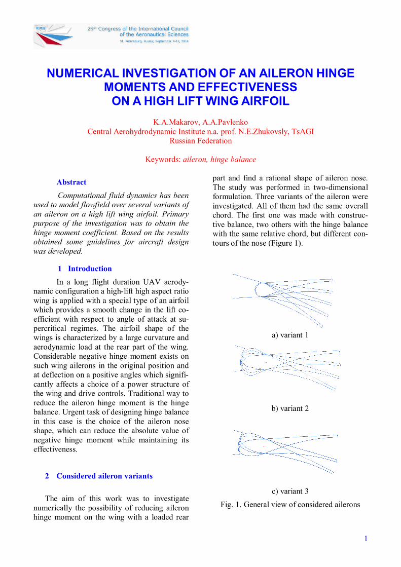
part and find a rational shape of aileron nose. The study was performed in two-dimensional formulation. Three variants of the aileron were investigated. All of them had the same overall chord. The first one was made with construc-tive balance, two others with the hinge balance with the same relative chord, but different con-tours of the nose (Figure 1).
a) variant 1
b) variant 2
c) variant 3
Fig. 1. General view of considered ailerons
MAKAROV K.A., PAVLENKO A.A.
2
The aileron of variant 1 was configured with constructive balance. The relative chord from the rotation axis is 22.5%. General view of the airfoil rear section with aileron deflected at angles of -20, -10, 0 and +10 ° is shown in Figure 1a.
The aileron of variant 2 was configured with hinge balance. The relative chord of hinge balance is equal to 22.5%, the relative chord from the rotation axis is 18.5%. The aileron nose section is formed by a circular arc, fitted with the contour of the profile. General view of the airfoil rear section with the aileron, de-flected at angles -20, -10, 0 and +10 ° is shown in Figure 1b. As can be seen, the nose part of this aileron variant is visibly out of the contour of the wing airfoil even at moderate angles of deflection. The variant 3 was also configured with hinge balance. Hinge balance relative chord is equal to 22.5%; the aileron relative chord from the rotation axis is equal to 18.5%. The upper sur-face of the aileron’s nose portion is formed by a parabola that fits with the profile contour at 80% of the balance chord, the bottom - on the ellipse that fits with the profile contour below the axis of rotation. General view of the airfoil with the aileron, deflected at angles of -20, 0 and +10 ° is shown in Figure 1c. Compared to variant 2 this version of aileron has less filled lower surface at nose section, which is much less stands out of the profile contour at the neg-ative aileron deflection angles. The upper sur-face of the nose portion has nearly the same fullness that of the variant 2, but the larger cur-vature radius at the protruding part.
3 Calculation conditions Numerical study of hinge moment and
effectiveness of several variants of the high-lift airfoil aileron in subsonic viscous gas flow has been performed in ANSYS CFX. Time-averaged Navier-Stokes equations with k-ω SST turbulence model solved in the two-dimensional formulation on a structured grid.
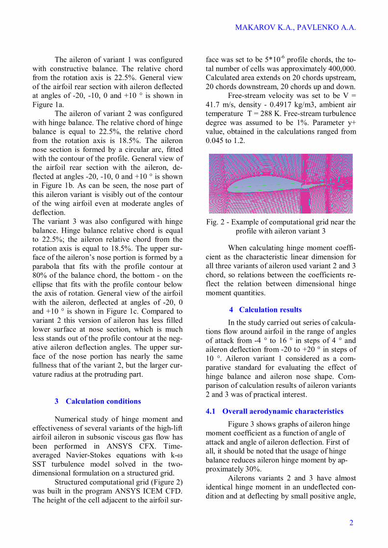
Structured computational grid (Figure 2) was built in the program ANSYS ICEM CFD. The height of the cell adjacent to the airfoil sur-
face was set to be 5*10-6 profile chords, the to-tal number of cells was approximately 400,000. Calculated area extends on 20 chords upstream, 20 chords downstream, 20 chords up and down.
Free-stream velocity was set to be V = 41.7 m/s, density - 0.4917 kg/m3, ambient air temperature T = 288 K. Free-stream turbulence degree was assumed to be 1%. Parameter y+ value, obtained in the calculations ranged from 0.045 to 1.2.
Fig. 2 - Example of computational grid near the
profile with aileron variant 3
When calculating hinge moment coeffi-cient as the characteristic linear dimension for all three variants of aileron used variant 2 and 3 chord, so relations between the coefficients re-flect the relation between dimensional hinge moment quantities.
4 Calculation results In the study carried out series of calcula-
tions flow around airfoil in the range of angles of attack from -4 ° to 16 ° in steps of 4 ° and aileron deflection from -20 to +20 ° in steps of 10 °. Aileron variant 1 considered as a com-parative standard for evaluating the effect of hinge balance and aileron nose shape. Com-parison of calculation results of aileron variants 2 and 3 was of practical interest.
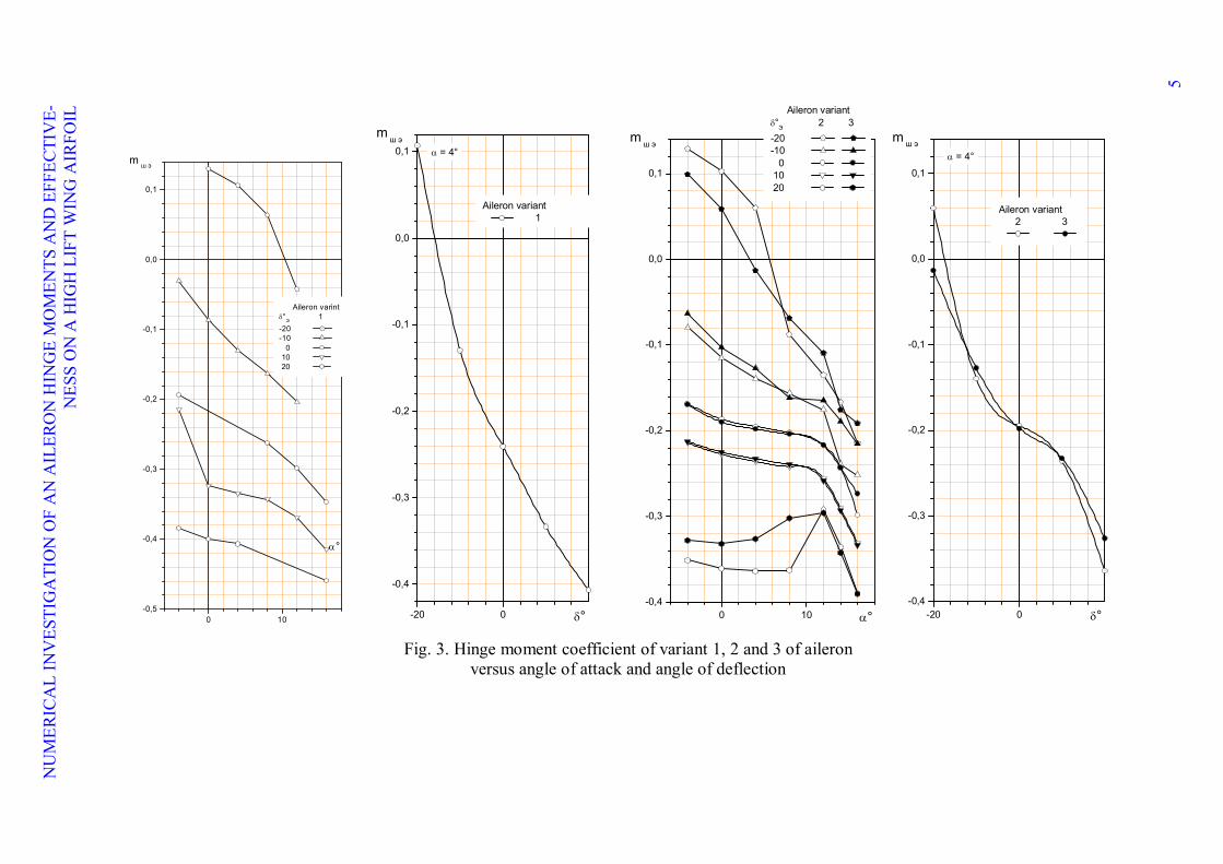
4.1 Overall aerodynamic characteristics Figure 3 shows graphs of aileron hinge
moment coefficient as a function of angle of attack and angle of aileron deflection. First of all, it should be noted that the usage of hinge balance reduces aileron hinge moment by ap-proximately 30%.
Ailerons variants 2 and 3 have almost identical hinge moment in an undeflected con-dition and at deflecting by small positive angle,
NUMERICAL INVESTIGATION OF AN AILERON HINGE MOMENTS AND EFFECTIVENESS ON A HIGH LIFT WING AIRFOIL
3
but when deflected by an angle over 10° aileron variant 3 hinge moment considera-bly smaller in the angle of attack range up to α ≈ 12°. Positive hinge moment incre-ments when aileron deflect by negative angles are not critical in this case, since undeflected aileron effected by significant negative hinge moment, and at aileron upward deflection the absolute value of hinge moment decreases. Nevertheless, it should be noted that when aileron de-flected on a small negative angle aileron variant 2 hinge moment coefficient incre-ment is a few less , and when deflection angles up to -20° is considerably greater than the aileron variant 3 at angle of attack up to α ≈ 8° (see Figure 3).
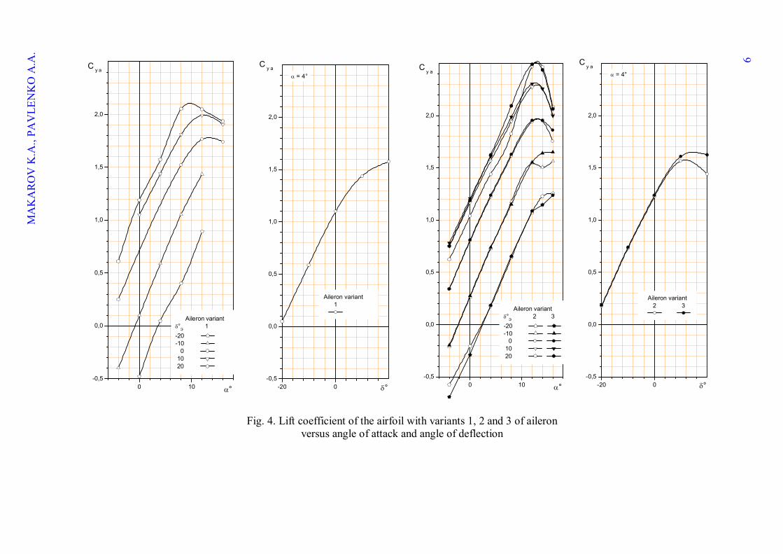
Aileron variant 3 has an advantage with respect to the aileron variant 2 also in terms of effectiveness. Figure 4 shows the variation of airfoil with aileron variant 2 and 3 lift coefficient by angle of attack and angle of deflection. It is seen that the in-crement of the lift coefficient of airfoil with aileron variant 3 on the positive an-gles of more than ≈ 10° at angles of at-tack up to ≈ 12° is significantly greater than that of aileron variant 2.
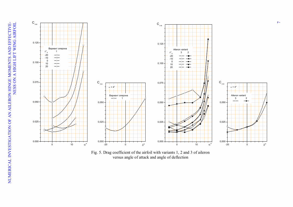
Another advantage of aileron vari-ant 3 is that it gives smaller increments of drag coefficient at deviation at large abso-lute angles (Figure 5). When you deflect aileron at positive angles over ≈ 10° sig-nificantly less drag observed at angles of
attack up to α ≈ 12 °,and when deflected large upward - at angles of attack up to α ≈ 8°.
4.2 Analysis of the flow fields near the air-foil rear section with the aileron
Benefits of aileron variant 3 with respect to the aileron variant 2 noted in the previous section caused by the different nature of sepa-rated flow development past on deflected ai-leron. This section analyzes the fields of veloc-ity, pressure coefficient and specific kinetic en-ergy of turbulence in the flow around the airfoil with aileron, and distribution of the pressure coefficient by the aileron surface for two con-figurations:
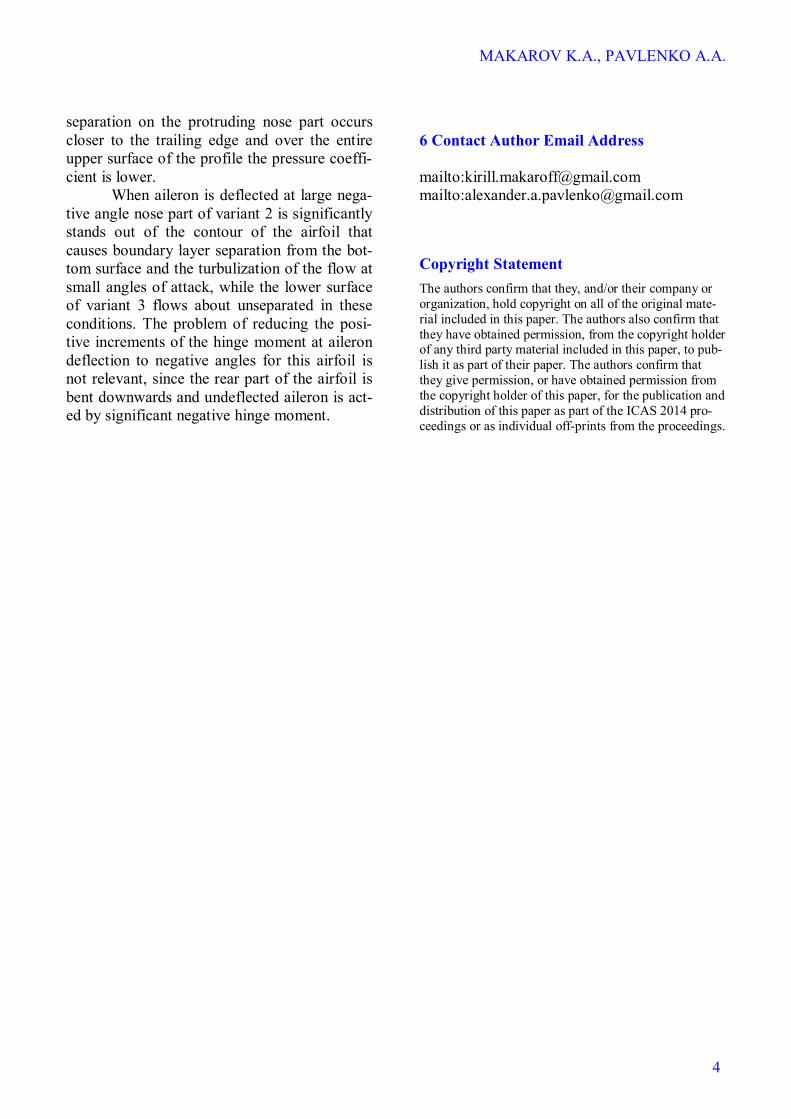
Angle of attack α, ° Aileron deflection Angle δ, °
4 +20 4 -20
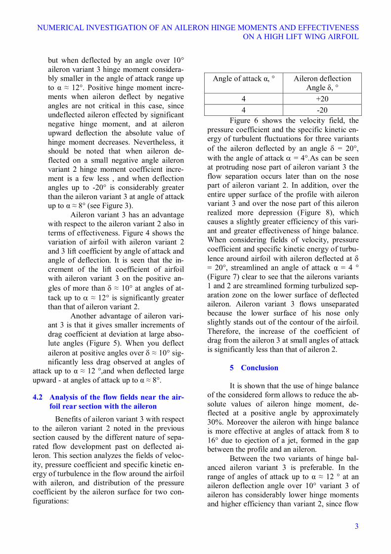
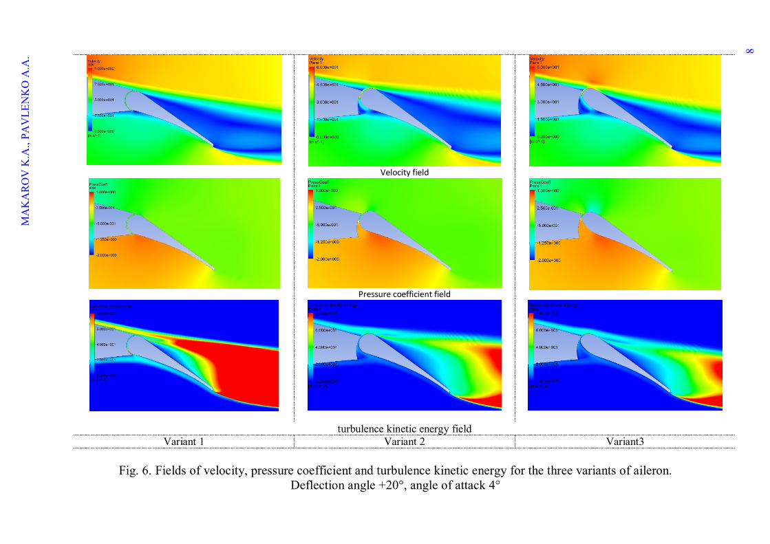
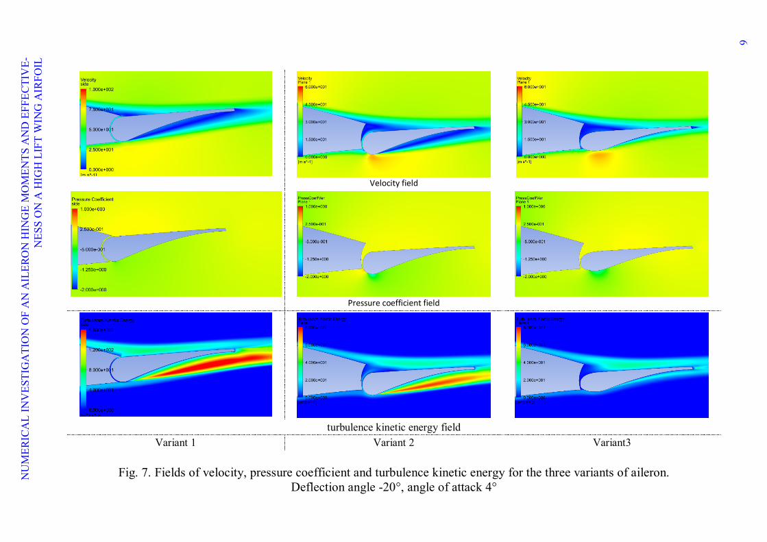
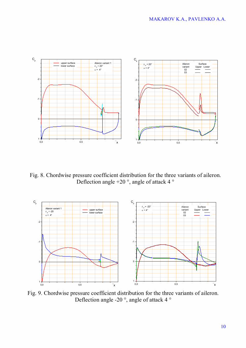
Figure 6 shows the velocity field, the pressure coefficient and the specific kinetic en-ergy of turbulent fluctuations for three variants of the aileron deflected by an angle = 20°, with the angle of attack = 4°.As can be seen at protruding nose part of aileron variant 3 the flow separation occurs later than on the nose part of aileron variant 2. In addition, over the entire upper surface of the profile with aileron variant 3 and over the nose part of this aileron realized more depression (Figure 8), which causes a slightly greater efficiency of this vari-ant and greater effectiveness of hinge balance. When considering fields of velocity, pressure coefficient and specific kinetic energy of turbu-lence around airfoil with aileron deflected at = 20°, streamlined an angle of attack α = 4 ° (Figure 7) clear to see that the ailerons variants 1 and 2 are streamlined forming turbulized sep-aration zone on the lower surface of deflected aileron. Aileron variant 3 flows unseparated because the lower surface of his nose only slightly stands out of the contour of the airfoil. Therefore, the increase of the coefficient of drag from the aileron 3 at small angles of attack is significantly less than that of aileron 2.
5 Conclusion It is shown that the use of hinge balance
of the considered form allows to reduce the ab-solute values of aileron hinge moment, de-flected at a positive angle by approximately 30%. Moreover the aileron with hinge balance is more effective at angles of attack from 8 to 16° due to ejection of a jet, formed in the gap between the profile and an aileron.
Between the two variants of hinge bal-anced aileron variant 3 is preferable. In the range of angles of attack up to α ≈ 12 ° at an aileron deflection angle over 10° variant 3 of aileron has considerably lower hinge moments and higher efficiency than variant 2, since flow
MAKAROV K.A., PAVLENKO A.A.
4
separation on the protruding nose part occurs closer to the trailing edge and over the entire upper surface of the profile the pressure coeffi-cient is lower.
When aileron is deflected at large nega-tive angle nose part of variant 2 is significantly stands out of the contour of the airfoil that causes boundary layer separation from the bot-tom surface and the turbulization of the flow at small angles of attack, while the lower surface of variant 3 flows about unseparated in these conditions. The problem of reducing the posi-tive increments of the hinge moment at aileron deflection to negative angles for this airfoil is not relevant, since the rear part of the airfoil is bent downwards and undeflected aileron is act-ed by significant negative hinge moment.
6 Contact Author Email Address mailto:[email protected] mailto:[email protected]
Copyright Statement The authors confirm that they, and/or their company or organization, hold copyright on all of the original mate-rial included in this paper. The authors also confirm that they have obtained permission, from the copyright holder of any third party material included in this paper, to pub-lish it as part of their paper. The authors confirm that they give permission, or have obtained permission from the copyright holder of this paper, for the publication and distribution of this paper as part of the ICAS 2014 pro-ceedings or as individual off-prints from the proceedings.
5
NU
MER
ICA
L IN
VES
TIG
ATI
ON
OF
AN
AIL
ERO
N H
ING
E M
OM
ENTS
AN
D E
FFEC
TIV
E-N
ESS
ON
A H
IGH
LIF
T W
ING
AIR
FOIL
0 10-0,5
-0,4
-0,3
-0,2
-0,1
0,0
0,1
°
Aileron varint °
Э 1
-20 -10 0 10 20
m ш э
-20 0
-0,4
-0,3
-0,2
-0,1
0,0
0,1
°
Aileron variant 1
m ш э = 4°
0 10-0,4
-0,3
-0,2
-0,1
0,0
0,1
°
Aileron variant °Э 2 3-20 -10 0 10 20
m ш э
-20 0-0,4
-0,3
-0,2
-0,1
0,0
0,1
°
Aileron variant 2 3
m ш э = 4°
Fig. 3. Hinge moment coefficient of variant 1, 2 and 3 of aileron
versus angle of attack and angle of deflection
MA
KA
RO
V K
.A.,
PAV
LEN
KO
A.A
.
6
0 10-0,5
0,0
0,5
1,0
1,5
2,0
Aileron variant °
Э 1
-20 -10 0 10 20
°
C y a
-20 0
-0,5
0,0
0,5
1,0
1,5
2,0
°
Aileron variant 1
C y a
= 4°
0 10-0,5
0,0
0,5
1,0
1,5
2,0
Aileron variant °
Э 2 3
-20 -10 0 10 20
°
C y a
-20 0-0,5
0,0
0,5
1,0
1,5
2,0
°
Aileron variant 2 3
C y a
= 4°
Fig. 4. Lift coefficient of the airfoil with variants 1, 2 and 3 of aileron versus angle of attack and angle of deflection
NU
MER
ICA
L IN
VES
TIG
ATI
ON
OF
AN
AIL
ERO
N H
ING
E M
OM
ENTS
AN
D E
FFEC
TIV
E-N
ESS
ON
A H
IGH
LIF
T W
ING
AIR
FOIL
7
0 100.000
0.025
0.050
0.075
0.100
0.125
Вариант элерона°
Э 1
-20 -10 0 10 20
°
C x a
-20 0
0,000
0,025
0,050
°
Вариант элерона 1
C x a
= 4°
0 100,000
0,025
0,050
0,075
0,100
0,125
Aileron variant °
Э 3 2
-20 -10 0 10 20
°
C x a
-20 00,000
0,025
0,050
°
Aileron variant 3 2
C x a
= 4°
Fig. 5. Drag coefficient of the airfoil with variants 1, 2 and 3 of aileron
versus angle of attack and angle of deflection
MA
KA
RO
V K
.A.,
PAV
LEN
KO
A.A
. 8
Fig. 6. Fields of velocity, pressure coefficient and turbulence kinetic energy for the three variants of aileron.
Deflection angle +20°, angle of attack 4°
Velocity field
Pressure coefficient field
turbulence kinetic energy field Variant 1 Variant 2 Variant3
NU
MER
ICA
L IN
VES
TIG
ATI
ON
OF
AN
AIL
ERO
N H
ING
E M
OM
ENTS
AN
D E
FFEC
TIV
E-N
ESS
ON
A H
IGH
LIF
T W
ING
AIR
FOIL
9
Velocity field
Pressure coefficient field
turbulence kinetic energy field
Variant 1 Variant 2 Variant3
Fig. 7. Fields of velocity, pressure coefficient and turbulence kinetic energy for the three variants of aileron. Deflection angle -20°, angle of attack 4°
MAKAROV K.A., PAVLENKO A.A.
10
0,0 0,51
0
-1
-2
x
upper surface lower surface
CpAileron variant 1 Э = 20° = 4°
0,0 0,51
0
-1
-2
x
CpAileron Surfacevariant Upper Lower 02 03
Э = 20° = 4°
Fig. 8. Chordwise pressure coefficient distribution for the three variants of aileron. Deflection angle +20 °, angle of attack 4 °
0,0 0,51
0
-1
-2
x
upper surface lower surface
Cp
Aileron variant 1
Э = -20
= 4°
0,0 0,51
0
-1
-2
Aileron Surfacevariant Upper Lower 02 03
x
Cp
Э = -20° = 4°
Fig. 9. Chordwise pressure coefficient distribution for the three variants of aileron.
Deflection angle -20 °, angle of attack 4 °