Embed Size (px)
Citation preview

Page 1
Published 10/06
PREFACE TO SECTION II ASSEMBLY INSTRUCTIONS
‘Wings & Ailerons’ There are TWO methods of wing covering for the Challenger. 1: Pre-sewn Sailcloth sock (Plain or Mylar coated) - This section 2: ‘Heat Shrinkable’ material covering - Section IIa NOTE: Some procedures are the same for both systems. E.G. aileron cover-ing. Please read Section II and Section IIa carefully A critical part of this section is the proper covering technique of the wing frames with your selected covering method. Proper installation will result in an efficient airfoil. As in Section I, pre-read these instructions until you have the procedure firmly in mind. Take your time and do your best to avoid unnecessary wrinkles in the finished product. Wrinkles in the wing covering are not only unattractive cosmetically, but reduce the efficiency of the airfoil and performance of the finished aircraft. If you have any questions prior to, or during assembly, please feel to contact the factory.
WARNING: The parts and hardware in the kit making up the Challenger are of special aircraft grade ! DO NOT attempt to substitute any part or hardware your-self. Contact the factory for assistance when replacement is necessary. Your life may depend on it !

Page 2
Published 10/06
‘WINGS & ALIERON - Pre-sewn sailcloth sock method.
Section II - Inventory for sailcloth kit.
Please conduct a complete and thorough inventory check prior to commencing your build. Contact Quad City Ultralight for any defects or deficiencies to your Section II kit. CHECK QTY PART # DESCRIPTION ( ) 1 Set of Instructions (this manual) ( ) 1 2W-100-R Wing panel (right) Standard wing ( ) 1 2W-100-L Wing panel (left) Standard wing ( ) 2 GSLS Wing socks - sailcloth (right and left) ( ) 1 A-100-R Aileron frame (right) Standard wing ( ) 1 A-100-L Aileron frame (left) Standard wing ( ) 8 A-007 Aileron piano hinges ( ) 100 SSD42SSB Short stainless steel pop rivets ( ) 60 SSD44SSB Long stainless steel pop rivets (Challenger II wings have 60 long rivets) ( ) 32 AD64ABS 3/16” Aluminum rivets ( ) 22 2-RB-1 Wing stay rods (ribs) ( ) 44 3675 Nylon wing stay rod ends ( ) 8 WS-1 Strut attach brackets ( ) 4 AN3-24A Bolts ( ) 4 AN3-23A Bolts ( ) 8 AN365-1032 Nyloc Nuts ( ) 1 ST-306 Set of Aileron fabric - heat shrinkable (right and left). ( ) 4 W6X Wing tip gussets NOTE: Some parts are shipped pre-assembled and labeled for proper location. Important: Inspect all parts of this kit for integrity. If any burs are present in the aluminum parts, remove these as described in Section I.

Page 3
Published 10/06
ASSEMBLY INSTRUCTIONS—Introduction
WINGS & AILERONS Pre-sewn sailcloth sock method.
CHALLENGER II—SECTION II We supply Dacron sailcloth socks to cover the wings, with heat shrinkable material attached to cover the wingtips. The sailcloth sock is lightweight, has a tear resistant weave and an ‘optional extra’ clear plastic coating (Mylar). The sailcloth is pre-sewn with pockets for the ribs. This method is for the Challenger II standard wing and Challenger I standard wing only. Heat shrinkable material is supplied for ailerons. NOTE: Challenger II standard wing can also be covered using the ‘Heat shrinkable’ method. For Clipped wing option, please refer to the ‘Heat shrinkable’ material method also. OBJECTIVE of SECTION II Upon completion of Section II of the assembly instructions, both wings and ailerons will be covered and hardware installed. Tools required: (not supplied) 1/2” or 1” soft brush. Electric drill, 3/16” & 1/8” drill bits. Razor blades. Scissors. Household clothes iron. Soldering gun with knife tip. Hammer. Center punch. Materials required: (supplied) Poly-tak adhesive. MEK Solvent. Other materials: (not supplied) Masking tape. Clear packing tape. #220 grit sandpaper wet or dry.
Typical completion time: 6.5 hours
IMPORTANT: BEFORE COVERING AILERONS, SEE PAGE 5 - 8 & 16.

Page 4
Published 10/06
How to find the centerline of rear spar.
Set Square
Side view of Rear Spar
Rub the metallic edge along the rear spar at this point. Enhance the mark with an erasable pen or pencil.
Parallel
You will need a centerline on the rear spar as a reference point to attach your aileron hinges. This procedure is done BEFORE fabric or covering is applied to the wing panel. Mark the rear spar where you intend to place the aileron hinges. At that location, place the ‘Set Square’ on the rear spar, as shown above. Make sure the square is parallel with the centerline of wing panel. Run the metallic part of the square along the rear of the wing spar. Make sure that you mark a long enough line to accommodate the hinge. Enhance the line with the use of a pencil or erasable marker pen. NOTE: DO NOT use permanent marker pens, this is tough to remove and will bleed through fabric if not thoroughly removed before covering. Once the location of hinge has been determined , clamp them in place (hose clamps work well) and ‘pre-drill’ the holes, ready for installation AFTER the covering has been applied. The use of Cleco’s in this procedure is highly recommended. Do not use rivets to secure hinges at this time. TIP: Keep a record of what hinge goes where. The holes you drill won’t be exactly the same for each hinge. Measure the distance of each hinge from a common reference point, I.E. the inboard end of wing spar. Once the fabric is on the wing panel, use a sharp point to locate your drilled holes.
Fig 1.

Page 5
Published 10/06
Pre - drilling aileron hinges, rear wing spar and aileron spar before covering. 1. Pre - drill hinges - 6 hinges with 4 holes each side and 2 hinges with 8 holes each side. Stagger holes in line with hinge barrels not in line with hinges spaces. (See photo below). 2. Clamp hinges to wing spar in proper location with hose clamps 3. Clamp hinges to aileron in proper location with hose clamps (see photo below for correct use of hose clamp). Inboard end of aileron should be 1 1/2” from inboard end of wing spar. 4. Make sure hinges do not interfere with wing rib stay pockets on sailcloth wings or with aileron ribs. Loosen clamps and move in necessary. 5. When happy with hinge locations and aileron travel, drill wing spar and aileron spar through predrilled holes in hinges. 6. Mark hinges with Sharpie maker with arrow pointing forward and number them L1, L2, L3, L4 for left wing and R1, R2, R3, R4 for right wing starting at the inboard hinges moving out board. After wing and aileron are covered and pained, these markings will help locate the proper position for each hinge. (See circled area in photo 1 below).. 7. Remove hinges and set aside.
How to install aileron hinges - before covering.
Hose clamp
Aileron Hinge A-007
Cleco’
Photo 1
Hinge barrel Hinge space
Identification marking

Page 6
Published 10/06
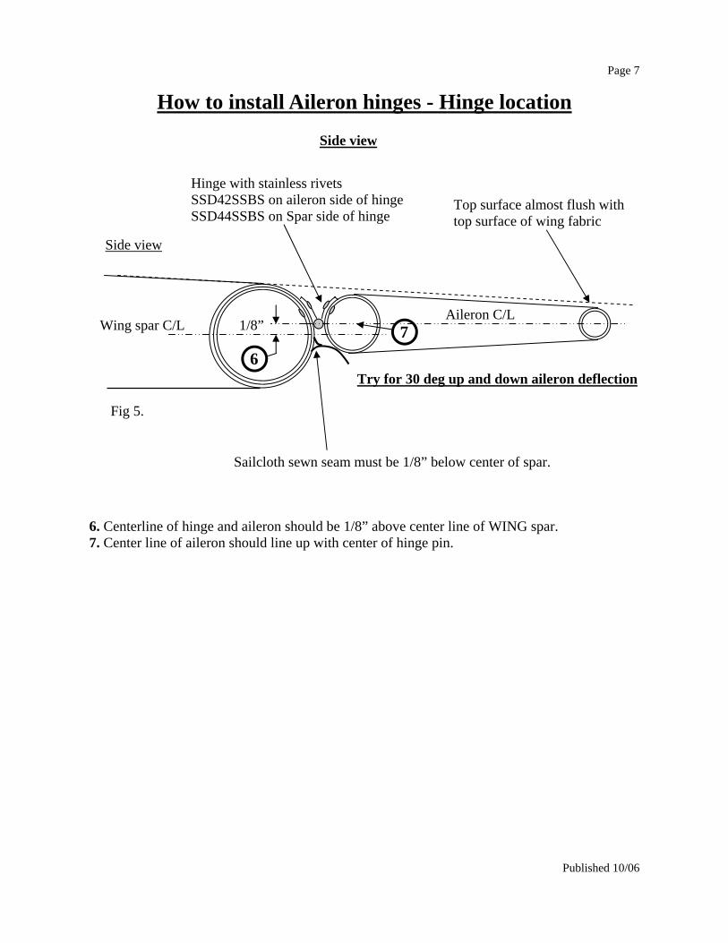
How to install Aileron hinges - Hinge location
4. Four rivets per side on all hinges except inboard hinge; which gets eight per side. The two center hinges must be spaced evenly between inboard and outboard hinges without Interfering with ribs or wing strut brackets. 5. Outboard hinge should be as close to spar end as possible but leave enough room to rivet the last wing rib stay.
Center aileron hinges
Rear Wing Spar
Aileron Fig 3.
4
1 1/2 “
Rear Wing Spar
Aileron Inboard aileron hinge
Control horn Top view
1
2 3
1. End of aileron spar must be one and one half inch from end of wing spar. 2. Inboard hinge should be as close to control horn as possible. 3. Stagger rivets to allow more aileron travel.
Fig 2.
Wing tip bow
Aileron outboard end
Fig 4.
Rear Wing Spar end
5 Outboard aileron hinge
Page 7
Published 10/06
Hinge with stainless rivets SSD42SSBS on aileron side of hinge SSD44SSBS on Spar side of hinge
1/8” Aileron C/L
Wing spar C/L
Top surface almost flush with top surface of wing fabric
Try for 30 deg up and down aileron deflection
Sailcloth sewn seam must be 1/8” below center of spar.
6 7
6. Centerline of hinge and aileron should be 1/8” above center line of WING spar. 7. Center line of aileron should line up with center of hinge pin.
Side view
Fig 5.
How to install Aileron hinges - Hinge location
Side view

Page 8
Published 10/06
5. Once trimmed, fold over and glue open ends. 50/50 mix
Trim excess material allowing 1 1/2” of fabric to contact L.E. Use 50/50 mix to glue overlap.
4. Cut and trim to fit around rib ends.
50/50 mix
2. Fold fabric over leading edge, approx 3/4 way round and glue through with 50/50 mix to fabric.
3. Fold remainder of fabric (Part # ST-306)over the aileron. Use 50/50 mix to glue fabric to leading edge
How to cover the Ailerons
1. Sand and clean aileron with MEK and tape aileron frame as was done during tail surface covering, in Section I. Coat the ribs and perimeter of aileron with smooth application of adhesive and let dry.
Step #1 - How to attach covering material ST-306 Fig 6.
Fig 7.
Fig 8.
Trim here
Side view
Fold over

Page 9
Published 10/06
How to cover the Ailerons Step #2 - How to ‘heat shrink’ Aileron fabric (ST-306) Use your skills aquired during the building of Section I Use Clothes iron to heat alternate sides of aileron to tighten the fabric. Be careful not to melt the fabric. (350 deg max). Heat entire material to remove wrinkles. Iron out all wrinkles at ends and on tubes. NOTE: Too much heat will distort the trailing edge tube and may bend the inboard and out-board ribs. 300 deg on iron works well. Repeat these steps for remaining aileron. Now you may paint the ailerons using the same meth-ods as the tail section.
Too much heat will over shrink the fabric and distort the trailing edge.
Iron set at 300 deg.
Gradually heat shrink the material. Use the iron evenly on both sides of aileron. Remove wrinkles in fabric and along all edges. Smooth out any excess glue build-up along the Edges.
Fig 9.

Page 10
Published 10/06
Leading edge
Trailing edge Secondary Compression strut
Drag strut Bow
How to assemble the wings.
W6X gusset
Zero porosity Dacron wingtip
2 place standard wing panel
Pull
Pull
Inboard end of Wing panel
Trailing edge sewn seam.
Leading edge
Sailcloth sock Part # GSLS
1/8” S.S.
Step #3 - How to attach W6X gusset. Form the W6X gusset around the leading edge spar, trailing edge spar and wing tip bow. Attach with 1/8” Stainless short rivets as shown.
Fig 10.
Fig 11.
Step #4. How to apply sailcloth to wing frame

Page 11
Published 10/06
How to assemble the wings
Step #4 - How to apply sailcloth sock to wing frame. Select the right-hand wing frame and place on a suitably large table or floor area to begin covering the wing. NOTE: The wing halves are marked left, right etc. Be sure the area used is clean and free of grease or dirt to prevent the sailcloth from being soiled or stained. Old bed sheets may be used to cover the assembly area to assure cleanliness. The wing frame must be taped wherever the wing sail will come in contact with it, to protect the sail from being stained by the aluminum,. We use 2” wide clear packaging tape: Works great! Do not put tape on wing tip bow! Remove air bubbles under tape by slitting with X-acto knife or razor blade. Select the right pre-sewn Dacron sailcloth “sock”. NOTE: this covering sock is supplied right side out and needs no reversing! Be sure that you have selected the right sock for the right wing panel. The Velcro strip will be to the root end, top side and the Dacron fabric will be outboard (wingtip) with trailing edge sewn seam at the trailing edge. Slide the wing sail onto the wing frame lining up the trailing edge sewn seam to the center line of the rear wing spar. NOTE: Check both wing socks to insure that the Velcro strips match up and hook together properly. Step #5 - How to rivet the sailcloth sock to the wing frame. Ref to Fig 12 page 12. With the sewn seam centered on the rear spar and the bottom side of the wing facing up, allow 1/4” of the spar ends to extend past the wing fabric end . Rivet as indicated at position 1. Center the trailing edge seam with the ‘wing tip end’ of the rear spar, pull tight to remove wrinkles along the trailing edge. Rivet with 3/16” Aluminum long rivet to hold in place. Rivet sail at position 3 allowing 1/4” of spar to show, then rivet at position 4 as shown. After riveting at all four corners, wing sail bottom should be flat and tight with no wrinkles. When riveting sail to spars, be sure to rivet where the fabric is doubled (at pocket locations). TIP: It is helpful to dab some 50/50 MEK-Adhesive mix on the sailcloth at the four corner locations before riveting to help prevent tearing the sailcloth at the rivet holes while tightening. Install 2 rivets per corner.

Page 12
Published 10/06
Underside of wing panel
Wing tip fabric
1
2
4
3 Pull tight until wrinkles and folds have gone.
Leading edge
Sewn seam
Sewn seam
3/16” Alu rivets
Rivet placement detail
How to assemble the wings.
Fig 12.
Step #5. How to apply sailcloth to wing frame

Page 13
Published 10/06
Wing rib stay 2RB-1
Plastic rod ends 3675
Insert Insert
Punch this side too.
Center punch Wing rib stay
Plastic rod ends
Allow 1/4” of spar ends to show
Push into channel
Wing rib stay
Sewn seam
Wing tip
Pre-sewn wing rib stay channels
How to assemble the wings.
3/16”Alu long
Drill through plastic stay end and rear spar with 3/16” drill bit, then rivet.
Leading edge
TOP
Step #6 - How to assemble wing rib stays 2RB-1 Insert plastic stay rod ends (Part # 3675) into each end of the stay rod tubes (Part # 2RB-1) as shown below. Be sure the plastic ends are completely seated against ends of tube and both plas-tic stay ends are positioned so that they lie flat against spars. Center punch tubes (as shown) to secure plastic stay ends in tubes.
Step #7 - How to install wing rib stays 2RB-1 To prevent oxidation stains on wing sail, cover stay tubes with clear packaging tape or sand and clean tubes with MEK and spray with clear laquer. Slide wing stays in through the pre-cut slits in the sewn wing rib pockets (see below). Be sure rear seam of wing sail stays centered on rear spar.
Fig 13.
Fig 14.
Step #8. - How to secure the wing rib stays

Page 14
Published 10/06
Underside of wing panel
Leading edge
Rear wing strut cut out
Wing tip
Solder-ing gun with Knife edge tip
How to assemble the wings.
Leading edge
Wing tip
Inboard hinge should be placed with the inboard edge next to the control horn
Middle hinges should be spaced evenly between inboard and out-board hinges, without interfering with ribs or wing strut brackets.
Outboard hinge should be placed as far out on wing spar as possible, without interfering with rib place-ment.
Top side of wing panel
Aileron
2 AN3-24A bolts 2 AN365-1032 Nyloc nuts 2 WS-1 Strut brackets. Note: 1/4” hole goes to ‘inboard side of wing panel.
2 AN3-23A bolts 2 AN365-1032 Nyloc nuts 2 WS-1 Strut brackets.
Trailing edge
Fig 15.
Fig 16.
1 7/8”
Hot knife
Step #10.How to cut wing strut bracket access slots in Sailcloth
Step #11.How to attach ailerons to wing panel.

Page 15
Published 10/06
How to assemble the wings. Step #8 - How to secure the wing rib stays While holding ribs all the way into their pockets, drill nylon stay rod ends and rear spar, then rivet in place with 3/16” aluminum long rivets Important:Do not rivet the rib near the strut bracket location at this time as it will interfere with the installation of the strut brackets. Step #9 - How to cover the wing tip bow. No illustration required. Sand and clean outside perimeter of wing tip bow with solvent. Use masking tape for gussets where needed. Following the same covering procedure as Section I, coat outside perimeter of the wing tip with 2 coats of adhesive and let dry 10 minutes or so. Pull the bottom wing tip fabric tight and free of wrinkles and attach to wing tip frame perimeter of the wing tip as before, with the use of 50/50 mix, and let dry. Pull top fabric tight, wrap around frame and attach with adhesive as before. Trim off excess fabric. After ample curing time for the adhesive has passed (15 minutes), use iron to shrink the wing tip fabric wrinkle free. Repeat these steps for the remaining wing. You may now paint the wing tips. Step #10 - How to cut wing strut bracket access slots in Sailcloth sock Locate the strut bracket holes on each spar and punch through fabric with a soldering gun. The first strut bracket hole is 116” from the inboard end of the wing spar (93—1/2” on clipped wings). For rear bracket holes, attach the outer strut bracket WS-1 to the trailing edge spar, us-ing the AN3-23A bolts supplied. Measure 1 7/8” from bracket to the sailcloth sock. This is the point at which you start the hot knife cut. Use a knife blade-type tip on your soldering gun to ‘hot knife’ slots in the Dacron . Use a wing strut bracket to size slots. These slots are for insertion and attachment of the strut attach brack-ets WS-1. Cut as small a slot as possible to permit assembly and improve finished appearance. NOTE: ‘Hot knife’ technique is preferred to cutting, since the Dacron sailcloth will not unravel or fray when hot knifed. Step #11 - How to install strut attach brackets WS-1. Be sure the 1/4” strut attach hole is nearest the inboard end of the wing. This will ensure that the brackets are facing the right direction . The leading edge is a 2” diameter spar and therefore requires the WS-1 brackets be attached with 2 AN3-24A bolts and 2 AN365-1032 nyloc nuts. With underside of wing facing up, the leading edge spar WS-1 brackets should be vertical when attached and the trailing edge spar WS-1 brackets should be angled in towards the leading edge of wing when attached. The trailing edge spar is 1/7/8” diameter and therefore requires the WS-1 brackets be attached with the shorter 2 AN3-23A bolts and 2 AN365-1032 nyloc nuts. Tighten the nuts down until firmly snug. Over tightening will cause distortion of the spar. Mini-mum of one full thread must be visible after the nyloc nut is installed. Step #12 - How to attach ailerons to wing panel. Carefully match the right hinge to the correct location and rivet in place with Stainless 1/8” rivets. For Spar attachment, use SSD44SSB (1/4” long). For aileron attachment, use SSD42SSB (1/8” short).

Page 16
Published 10/06
Finishing up sailcloth method…. Your wings should now be completed, wrinkle free and taught. Before painting the wing tips, you have the opportunity to apply some 2” seam tape along the underside of the wingtip where the fabric overlaps. This will clean up the look of the overlap. We supply a 2’ seam tape in the kit, but is somewhat difficult to use for ‘curved’ edges. It is ideal for the straight edges you will make on the fuselage. You can opt to purchase some tape specially manufactured for curved applications. It’s called ‘Bias’ tape and is available from most reputable aircraft hardware supply companies in various widths. Apply the 2” seam tape to the overlap by using a 50/50 mix. BE CAREFUL not to apply too much and avoid coating the entire width of the seam, it is possible to pop open the overlap if the underlying glue gets too wet. Alternatively you can use poly brush fabric sealer, be sure to apply enough to give the tape and fabric a good covering to ensure a good adhesion. Once the tape is dry, you will notice that the ‘pinked edging’ is fairly rough. You can use an iron (set at 300 deg ) and run the edge of the iron along the edge of the pinked tape. This will smooth out most of the roughness. Careful not to overheat the tape or it will disfigure and also burn a hole in the fabric. Before applying paint etc, you can use a very light grade wet or dry abrasive paper (use lots of water) and very gently rub the edges until you get a smoother finish. Repeat this process once you have covered the fabric with fabric sealer (E.G. poly brush). Warning: Too much pressure could result in rubbing a hole into the fabric. The edges can also be ‘filled’ with paint during the spray painting process. NOTE: DO NOT paint optional Mylar coated sails—Just the wing tips/bows only. This process is the same for finishing up on the fuselage covering, and even for the tail section if so desired. Section II Sailcloth assembly is now complete. Take some time to admire your work and inspect entire assembly. Check to be sure strut bracket attach nuts have been tightened properly, all rivets have seated properly etc.