Embed Size (px)
Citation preview
Trans. JSASS Aerospace Tech. JapanVol. 16, No. 2, pp. 105-109, 2018DOI: 10.2322/tastj.16.105
105
Copyright© 2018 by the Japan Society for Aeronautical and Space Sciences and ISTS. All rights reserved.
Numerical Investigation of Neutral-Injection Effect
on an Electrodeless Plasma Thruster
By Kazuki TAKASE,1) Kazunori TAKAHASHI,2) and Yoshinori TAKAO3)
1)Department of Systems Integration, Yokohama National University, Yokohama, Japan
2)Department of Electrical Engineering, Tohoku University, Sendai, Japan 3)Division of Systems Research, Yokohama National University, Yokohama, Japan
(Received June 30th, 2017)
The effect of neutral gas injection from downstream side of electrodeless thrusters is numerically investigated using two-dimensional axisymmetric particle-in-cell simulations with Monte Carlo collisions algorithm (PIC/MCC) for charged particles, and direct simulation Monte Carlo (DSMC) for neutrals, where the propellant gas is injected from both the upstream and downstream sides of the source cavity. The analysis is performed for various ratios of the gas injection from the upstream and downstream sides, while maintaining the total gas flow rate of 30 g/s. The PIC/MCC and DSMC numerical results show that the performance degradation induced by neutral depletion is inhibited and the plasma density peak shifts to the downstream side of the source when increasing the downstream gas injection. As a result, the downstream gas injection is effective for performance improvement by applying external magnetic fields. This tendency is in qualitative agreement with recent experiments.
Key Words: Electric Propulsion, Helicon Plasma Thruster, Neutral Depletion, PIC/MCC, DSMC
Nomenclature
B : magnetic field E : electric field j : plasma current density
Q : neutral gas flow rate v : velocity x : position : charge density
Subscripts down : downstream ex : external r : radial direction up : upstream z : axial direction θ : azimuthal direction
1. Introduction
Researches of high-power electric thrusters have been performed for development of all-electric satellites and space probes over the world. For example, Boeing has already developed a 5 kW-class XIPS mounted on 702SP,1) and JAXA is currently developing 6 kW-class hall thrusters mounted on Engineering Test Satellite Ⅸ (ETS-Ⅸ).2) While this enlargement of existing thrusters is promising, helicon plasma thrusters (HPTs),3-6) which consist of a high-density helicon plasma source and a magnetic nozzle, could be also one of the candidates for such high-power thrusters. Since high-density plasma is generated in HPTs, it is expected to generate large thrust with no electrode exposed to the plasma. However, the
propulsion performance of HPTs is still low compared to the conventional thrusters. It has been reported that the plasma density profile having a maximum in the upstream region of the discharge chamber cause a non-negligible loss of the axial momentum to the wall in an experiment.7) The upstream density peak is induced by the neutral depletion as demonstrated by an experiment and a PIC simulation.8,9) After that, Takahashi et al.10) demonstrated that neutral gas injection from not only upstream side but also downstream side of the thruster improved propulsion performance because of the inhibition of neutral depletion effect, where the plasma density profile became uniform in the discharge chamber. This effect has also been confirmed in some numerical simulations with a simple calculation model, where the thruster exit is bounded by a metal wall for the PIC simulation. 11-13) However, it is insufficient in this model to compare the results with the experiment quantitatively due to this simplification since the plasma is expected to expand downstream the thruster exit. Then, the calculation model is improved by expanding the simulation area and numerical simulations with this new model are performed in this study. Comparison between the previous and the new models is also carried out and discussed. 2. Numerical Model We have employed two-dimensional axisymmetric particle-in-cell simulations with Monte Carlo collisions algorithm (PIC/MCC) for charged particles and the direct simulation Monte Carlo (DSMC) method for neutrals. In this section, the numerical models and conditions for each simulation are described. 2.1. PIC/MCC simulations
Trans. JSASS Aerospace Tech. Japan Vol. 16, No. 2 (2018)
106
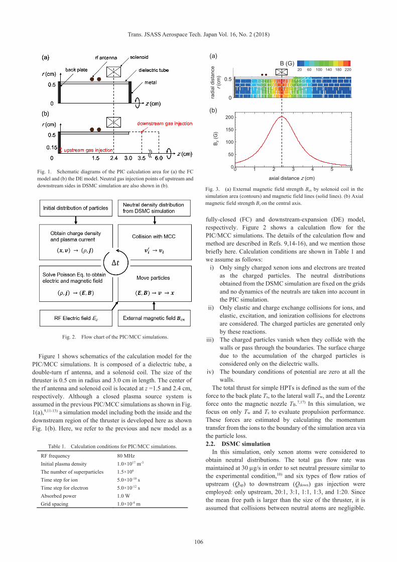
Figure 1 shows schematics of the calculation model for the PIC/MCC simulations. It is composed of a dielectric tube, a double-turn rf antenna, and a solenoid coil. The size of the thruster is 0.5 cm in radius and 3.0 cm in length. The center of the rf antenna and solenoid coil is located at z =1.5 and 2.4 cm, respectively. Although a closed plasma source system is assumed in the previous PIC/MCC simulations as shown in Fig. 1(a),9,11-13) a simulation model including both the inside and the downstream region of the thruster is developed here as shown Fig. 1(b). Here, we refer to the previous and new model as a
fully-closed (FC) and downstream-expansion (DE) model, respectively. Figure 2 shows a calculation flow for the PIC/MCC simulations. The details of the calculation flow and method are described in Refs. 9,14-16), and we mention those briefly here. Calculation conditions are shown in Table 1 and we assume as follows:
i) Only singly charged xenon ions and electrons are treated as the charged particles. The neutral distributions obtained from the DSMC simulation are fixed on the grids and no dynamics of the neutrals are taken into account in the PIC simulation.
ii) Only elastic and charge exchange collisions for ions, and elastic, excitation, and ionization collisions for electrons are considered. The charged particles are generated only by these reactions.
iii) The charged particles vanish when they collide with the walls or pass through the boundaries. The surface charge due to the accumulation of the charged particles is considered only on the dielectric walls.
iv) The boundary conditions of potential are zero at all the walls.
The total thrust for simple HPTs is defined as the sum of the force to the back plate Ts, to the lateral wall Tw, and the Lorentz force onto the magnetic nozzle TB.7,17) In this simulation, we focus on only Tw and Ts to evaluate propulsion performance. These forces are estimated by calculating the momentum transfer from the ions to the boundary of the simulation area via the particle loss. 2.2. DSMC simulation In this simulation, only xenon atoms were considered to obtain neutral distributions. The total gas flow rate was maintained at 30 g/s in order to set neutral pressure similar to the experimental condition,10) and six types of flow ratios of upstream (Qup) to downstream (Qdown) gas injection were employed: only upstream, 20:1, 3:1, 1:1, 1:3, and 1:20. Since the mean free path is larger than the size of the thruster, it is assumed that collisions between neutral atoms are negligible.
Fig. 1. Schematic diagrams of the PIC calculation area for (a) the FC model and (b) the DE model. Neutral gas injection points of upstream and downstream sides in DSMC simulation are also shown in (b).
Fig. 2. Flow chart of the PIC/MCC simulations.
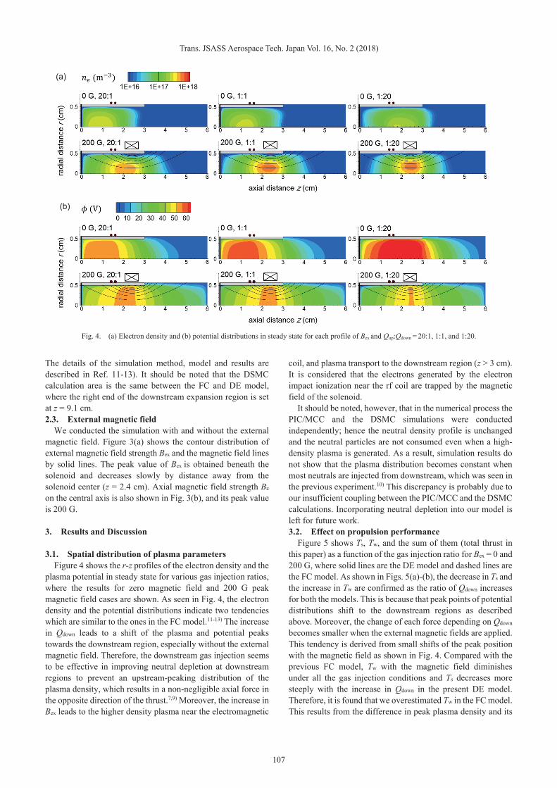
Fig. 3. (a) External magnetic field strength Bex by solenoid coil in the simulation area (contours) and magnetic field lines (solid lines). (b) Axial magnetic field strength Bz on the central axis.
20 60 100 140 180 220
0 1 2 3 4 5 60
0.5
B (G)
0 1 2 3 4 5 60
50
100
150
200
radi
al d
ista
nce
r(cm
)
axial distance z (cm)
B z(G
)
(a)
(b)
Table 1. Calculation conditions for PIC/MCC simulations.
RF frequency 80 MHz Initial plasma density 1.0×10¹⁷ m-3
The number of superparticles 1.5×10⁶ Time step for ion 5.0×10⁻¹⁰ s
Time step for electron 5.0×10⁻¹² s
Absorbed power 1.0 W Grid spacing 1.0×10⁻⁴ m
Trans. JSASS Aerospace Tech. Japan Vol. 16, No. 2 (2018)
107
The details of the simulation method, model and results are described in Ref. 11-13). It should be noted that the DSMC calculation area is the same between the FC and DE model, where the right end of the downstream expansion region is set at z = 9.1 cm. 2.3. External magnetic field
We conducted the simulation with and without the external magnetic field. Figure 3(a) shows the contour distribution of external magnetic field strength Bex and the magnetic field lines by solid lines. The peak value of Bex is obtained beneath the solenoid and decreases slowly by distance away from the solenoid center (z = 2.4 cm). Axial magnetic field strength Bz on the central axis is also shown in Fig. 3(b), and its peak value is 200 G.
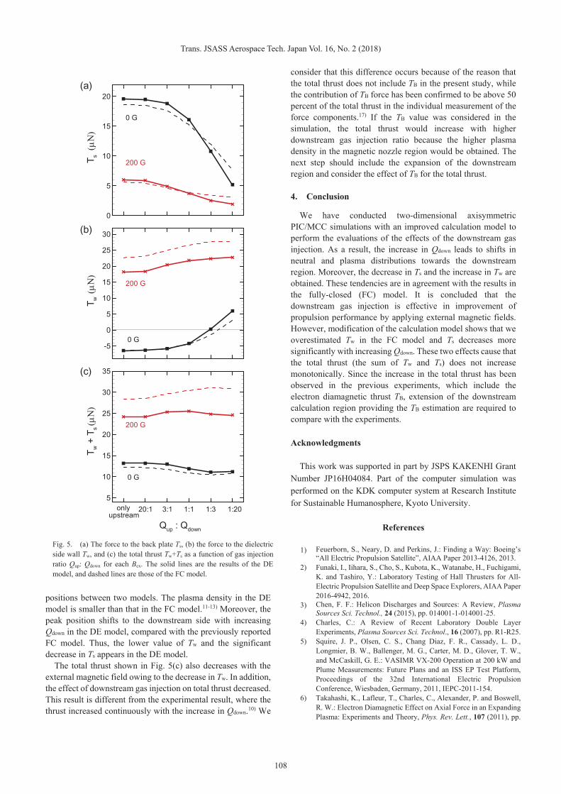
3. Results and Discussion 3.1. Spatial distribution of plasma parameters Figure 4 shows the r-z profiles of the electron density and the plasma potential in steady state for various gas injection ratios, where the results for zero magnetic field and 200 G peak magnetic field cases are shown. As seen in Fig. 4, the electron density and the potential distributions indicate two tendencies which are similar to the ones in the FC model.11-13) The increase in Qdown leads to a shift of the plasma and potential peaks towards the downstream region, especially without the external magnetic field. Therefore, the downstream gas injection seems to be effective in improving neutral depletion at downstream regions to prevent an upstream-peaking distribution of the plasma density, which results in a non-negligible axial force in the opposite direction of the thrust.7,9) Moreover, the increase in Bex leads to the higher density plasma near the electromagnetic
coil, and plasma transport to the downstream region (z > 3 cm). It is considered that the electrons generated by the electron impact ionization near the rf coil are trapped by the magnetic field of the solenoid.
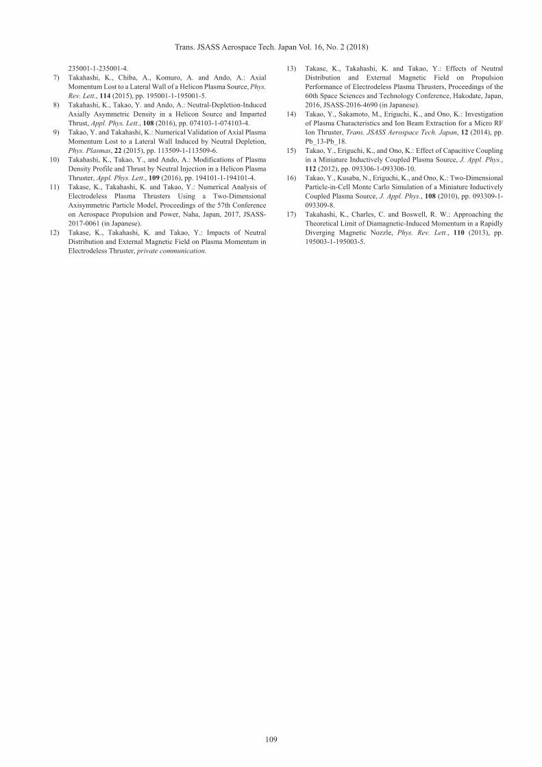
It should be noted, however, that in the numerical process the PIC/MCC and the DSMC simulations were conducted independently; hence the neutral density profile is unchanged and the neutral particles are not consumed even when a high-density plasma is generated. As a result, simulation results do not show that the plasma distribution becomes constant when most neutrals are injected from downstream, which was seen in the previous experiment.10) This discrepancy is probably due to our insufficient coupling between the PIC/MCC and the DSMC calculations. Incorporating neutral depletion into our model is left for future work. 3.2. Effect on propulsion performance Figure 5 shows Ts, Tw, and the sum of them (total thrust in this paper) as a function of the gas injection ratio for Bex = 0 and 200 G, where solid lines are the DE model and dashed lines are the FC model. As shown in Figs. 5(a)-(b), the decrease in Ts and the increase in Tw are confirmed as the ratio of Qdown increases for both the models. This is because that peak points of potential distributions shift to the downstream regions as described above. Moreover, the change of each force depending on Qdown becomes smaller when the external magnetic fields are applied. This tendency is derived from small shifts of the peak position with the magnetic field as shown in Fig. 4. Compared with the previous FC model, Tw with the magnetic field diminishes under all the gas injection conditions and Ts decreases more steeply with the increase in Qdown in the present DE model. Therefore, it is found that we overestimated Tw in the FC model. This results from the difference in peak plasma density and its
Fig. 4. (a) Electron density and (b) potential distributions in steady state for each profile of Bex and Qup:Qdown = 20:1, 1:1, and 1:20.
(a)
(b)
Trans. JSASS Aerospace Tech. Japan Vol. 16, No. 2 (2018)
108
positions between two models. The plasma density in the DE model is smaller than that in the FC model.11-13) Moreover, the peak position shifts to the downstream side with increasing Qdown in the DE model, compared with the previously reported FC model. Thus, the lower value of Tw and the significant decrease in Ts appears in the DE model.
The total thrust shown in Fig. 5(c) also decreases with the external magnetic field owing to the decrease in Tw. In addition, the effect of downstream gas injection on total thrust decreased. This result is different from the experimental result, where the thrust increased continuously with the increase in Qdown.10) We
consider that this difference occurs because of the reason that the total thrust does not include TB in the present study, while the contribution of TB force has been confirmed to be above 50 percent of the total thrust in the individual measurement of the force components.17) If the TB value was considered in the simulation, the total thrust would increase with higher downstream gas injection ratio because the higher plasma density in the magnetic nozzle region would be obtained. The next step should include the expansion of the downstream region and consider the effect of TB for the total thrust. 4. Conclusion We have conducted two-dimensional axisymmetric PIC/MCC simulations with an improved calculation model to perform the evaluations of the effects of the downstream gas injection. As a result, the increase in Qdown leads to shifts in neutral and plasma distributions towards the downstream region. Moreover, the decrease in Ts and the increase in Tw are obtained. These tendencies are in agreement with the results in the fully-closed (FC) model. It is concluded that the downstream gas injection is effective in improvement of propulsion performance by applying external magnetic fields. However, modification of the calculation model shows that we overestimated Tw in the FC model and Ts decreases more significantly with increasing Qdown. These two effects cause that the total thrust (the sum of Tw and Ts) does not increase monotonically. Since the increase in the total thrust has been observed in the previous experiments, which include the electron diamagnetic thrust TB, extension of the downstream calculation region providing the TB estimation are required to compare with the experiments. Acknowledgments This work was supported in part by JSPS KAKENHI Grant Number JP16H04084. Part of the computer simulation was performed on the KDK computer system at Research Institute for Sustainable Humanosphere, Kyoto University.
References
1) Feuerborn, S., Neary, D. and Perkins, J.: Finding a Way: Boeing’s “All Electric Propulsion Satellite”, AIAA Paper 2013-4126, 2013.
2) Funaki, I., Iihara, S., Cho, S., Kubota, K., Watanabe, H., Fuchigami, K. and Tashiro, Y.: Laboratory Testing of Hall Thrusters for All-Electric Propulsion Satellite and Deep Space Explorers, AIAA Paper 2016-4942, 2016.
3) Chen, F. F.: Helicon Discharges and Sources: A Review, Plasma Sources Sci. Technol., 24 (2015), pp. 014001-1-014001-25.
4) Charles, C.: A Review of Recent Laboratory Double Layer Experiments, Plasma Sources Sci. Technol., 16 (2007), pp. R1-R25.
5) Squire, J. P., Olsen, C. S., Chang Diaz, F. R., Cassady, L. D., Longmier, B. W., Ballenger, M. G., Carter, M. D., Glover, T. W., and McCaskill, G. E.: VASIMR VX-200 Operation at 200 kW and Plume Measurements: Future Plans and an ISS EP Test Platform, Proceedings of the 32nd International Electric Propulsion Conference, Wiesbaden, Germany, 2011, IEPC-2011-154.
6) Takahashi, K., Lafleur, T., Charles, C., Alexander, P. and Boswell, R. W.: Electron Diamagnetic Effect on Axial Force in an Expanding Plasma: Experiments and Theory, Phys. Rev. Lett., 107 (2011), pp.
Fig. 5. (a) The force to the back plate Ts, (b) the force to the dielectric side wall Tw, and (c) the total thrust Tw+Ts as a function of gas injection ratio Qup: Qdown for each Bex. The solid lines are the results of the DE model, and dashed lines are those of the FC model.
× ××
×× ×
0
5
10
15
20
200 G
onlyupstream
20:1 3:1 1:1 1:3 1:20
0 G
Qup : Qdown
T s
× ×× × × ×
-5
0
5
10
15
20
25
30
200 G
onlyupstream
20:1 3:1 1:1 1:3 1:20
0 G
Qup : Qdown
T w
× × × × × ×
5
10
15
20
25
30
35
200 G
onlyupstream
20:1 3:1 1:1 1:3 1:20
0 G
Qup : Qdown
T w+T s
(a)
(b)
(c)
Trans. JSASS Aerospace Tech. Japan Vol. 16, No. 2 (2018)
109
235001-1-235001-4. 7) Takahashi, K., Chiba, A., Komuro, A. and Ando, A.: Axial
Momentum Lost to a Lateral Wall of a Helicon Plasma Source, Phys. Rev. Lett., 114 (2015), pp. 195001-1-195001-5.
8) Takahashi, K., Takao, Y. and Ando, A.: Neutral-Depletion-Induced Axially Asymmetric Density in a Helicon Source and Imparted Thrust, Appl. Phys. Lett., 108 (2016), pp. 074103-1-074103-4.
9) Takao, Y. and Takahashi, K.: Numerical Validation of Axial Plasma Momentum Lost to a Lateral Wall Induced by Neutral Depletion, Phys. Plasmas, 22 (2015), pp. 113509-1-113509-6.
10) Takahashi, K., Takao, Y., and Ando, A.: Modifications of Plasma Density Profile and Thrust by Neutral Injection in a Helicon Plasma Thruster, Appl. Phys. Lett., 109 (2016), pp. 194101-1-194101-4.
11) Takase, K., Takahashi, K. and Takao, Y.: Numerical Analysis of Electrodeless Plasma Thrusters Using a Two-Dimensional Axisymmetric Particle Model, Proceedings of the 57th Conference on Aerospace Propulsion and Power, Naha, Japan, 2017, JSASS-2017-0061 (in Japanese).
12) Takase, K., Takahashi, K. and Takao, Y.: Impacts of Neutral Distribution and External Magnetic Field on Plasma Momentum in Electrodeless Thruster, private communication.
13) Takase, K., Takahashi, K. and Takao, Y.: Effects of Neutral Distribution and External Magnetic Field on Propulsion Performance of Electrodeless Plasma Thrusters, Proceedings of the 60th Space Sciences and Technology Conference, Hakodate, Japan, 2016, JSASS-2016-4690 (in Japanese).
14) Takao, Y., Sakamoto, M., Eriguchi, K., and Ono, K.: Investigation of Plasma Characteristics and Ion Beam Extraction for a Micro RF Ion Thruster, Trans. JSASS Aerospace Tech. Japan, 12 (2014), pp. Pb_13-Pb_18.
15) Takao, Y., Eriguchi, K., and Ono, K.: Effect of Capacitive Coupling in a Miniature Inductively Coupled Plasma Source, J. Appl. Phys., 112 (2012), pp. 093306-1-093306-10.
16) Takao, Y., Kusaba, N., Eriguchi, K., and Ono, K.: Two-Dimensional Particle-in-Cell Monte Carlo Simulation of a Miniature Inductively Coupled Plasma Source, J. Appl. Phys., 108 (2010), pp. 093309-1-093309-8.
17) Takahashi, K., Charles, C. and Boswell, R. W.: Approaching the Theoretical Limit of Diamagnetic-Induced Momentum in a Rapidly Diverging Magnetic Nozzle, Phys. Rev. Lett., 110 (2013), pp. 195003-1-195003-5.


![INTEGRATED NUMERICAL SIMULATION OF INJECTION MOLDING … · injection molding filling simulation [8]. Numerical experiments confirm the reliability and efficiency of the solver. Integrated](https://img.pdfslide.net/doc/110x75/5d0d0f7388c993ed388b4830/integrated-numerical-simulation-of-injection-molding-injection-molding-filling.jpg)