Embed Size (px)
Citation preview
Li, L., et al.: Numerical Investigation on Dynamic Characteristics of Hydrodynamic Bearing THERMAL SCIENCE: Year 2017, Vol. 21, Suppl. 1, pp. S201-S208 S201
NUMERICAL INVESTIGATION ON DYNAMIC CHARACTERISTICS OF HYDRODYNAMIC BEARING
by
Liangliang LI, Yunzhu LI, and Yonghui XIE *
Shaanxi Engineering Laboratory of Turbomachinery and Power Equipment, School of Energy and Power Engineering, Xi’an Jiaotong University, Xi’an, China
Original scientific paper https://doi.org/10.2298/TSCI17S1201L
In this paper, both the steady-state and transient-state of the films flow are inves-tigated by CFD. The journal bearing dynamic characteristics such as the load capacity, damping and stiffness coefficients for several eccentricity, and length over diameter ratio (L/D) are obtained and compared with each other in different working conditions. Furthermore, the variation of various research parameters with eccentricity and L/D are also illustrated in detail.Key words: hydrodynamic bearing, load capacity, eccentricity, L/D ratios,
damping coefficient, stiffness coefficient
Introduction
Hydrodynamic bearing is one of the most widely used types of the sliding bearings in engineering applications. As for now, the research methods of hydrodynamic bearing mainly involve experimental investigation and numerical simulation. With the popularity of computer technology and the rapid development of CFD methods, CFD simulation has gradually become the mainstream method to obtain the dynamic characteristics of hydrodynamic bearing [1, 2].
Four stiffness coefficients and four damping coefficients were used to establish a flex-ible bearing-rotor system model by Lund [3], which revealed the eddy characteristic of the bearing-rotor system. And infinitesimal perturbation method was employed by Lund [4, 5] to obtain the linear stiffness and damping coefficients about journal equilibrium position. The numerical solution of the Reynolds equation was gained by Sivak and Sivak [6] using the im-proved Ritz method. The variation of stiffness and damping coefficients with large dynamic load of rotary compressor was studied by Hattori [7]. Dynamic coefficients under different perturbation amplitude were calculated by Qiu and Tieu [8], and the results emerged that the perturbation displacement and velocity should be less than 5% and 4%, respectively, to ensure the accuracy of damping and stiffness coefficient calculations. The non-linear properties of dynamic bearing under different L/D ratios are investigated by Sawicki and Rao [9], and the change rules of higher order damping and stiffness coefficients were described. The dynamic characteristics of hydrodynamic bearing lubricated with both Newtonian fluid and non-Newto-nian fluid were studied by Gertzos et al. [10] using dynamic mesh technology, and the variation law of dimensionless friction with eccentricity was presented. The fluid film filed was simulated using CFX-TASC flow and the damping and stiffness properties of the bearing were gained by
* Corresponding author, e-mail: [email protected]
Li, L., et al.: Numerical Investigation on Dynamic Characteristics of Hydrodynamic Bearing S202 THERMAL SCIENCE: Year 2017, Vol. 21, Suppl. 1, pp. S201-S208
Guo et al. [11] using different methods, which verified the calculation accuracy of the damping and stiffness coefficients by numerical method. Experimental method was adopted by Lijesh et al. [12] to investigate the damping and stiffness properties of non-contact passive magnetic bearings, and a hybrid bearing was proposed through pendulum test. The non-linear charac-teristics of oil film were obtained under the large amplitude movement of journal by Wood et al. [13], considering the higher order terms in the bearing reaction expansion. The minimum square method was adopted by Muller-Karger et al. [14] to adjust dynamic coefficients, and the calculation results revealed that the non-linearity depends on the size and shape of the orbital motion. The aim of the paper is to investigate both the steady- and transient-states of the films flow with the help of CFD.
The CFD theory and dynamic characteristics calculation method
At present, commercial software has been widely used in the calculation of sliding bearings [15, 16]. Solving the Reynolds equation is an important issue in the numerical solution of hydrodynamic bearings [17, 18]. The dynamic Reynolds equation is usually used as a lubri-cation equation for calculating the stiffness and damping coefficients of hydrodynamic bearings [19]. The Reynolds equation describing the motion of the fluid film is:
3
( )12h p hU Vµ
∇ ∇ = ∇ −
(1)
where U is the velocity of journal surface, and V is the film velocity.Generally, the oil film can only withstand positive pressure. When the film pressure
drops down to the atmosphere pressure, rupture of film or cavitation occurs. The half-Som-merfeld boundary condition, which divides the whole oil film into complete oil film zone and rupture zone, specifies the magnitude of static pressure in rupture zone as zero Pascal.
The damping and stiffness coefficients can be obtained by finite difference method in the case of small disturbance. According to perturbation theory, oil film force could be linear-ized. The increment of fluid film force components can be expressed:
∆ ′ ∆
= + ∆ ′∆
xy xyx xx xx
y yx yxyy yy
K CF K Cx xF K CK y C y
(2)
where ΔFx and ΔFy are the change of oil film force in two directions, respectively, Kxx and Kyy are direct stiffness coefficients, Kxy and Kyx are cross stiffness coefficients, Cxx and Cyy are direct damping coefficients, Cxy and Cyx are cross damping coefficients, Δx and Δy are perturbation displacement in two directions, and ′x and ′y are perturbation velocity in two directions.
The stiffness and damping coefficients can be calculated by eq. (3):
∆ ∆∆ ∆= = = =
′ ′∆ ∆∆ ∆ ∆ ∆
= = = =′ ′∆ ∆
dyx vyxdxx vxxxx yx xx yx
dxy dyy vxy vyyxy yy xy yy
F FF FK K C Cx x x x
F F F FK K C C
y y y y
(3)
where ∆ dijF is the change of oil film force caused by perturbation displacement, and ∆ vijF is the change of oil film force caused by perturbation velocity.
Li, L., et al.: Numerical Investigation on Dynamic Characteristics of Hydrodynamic Bearing THERMAL SCIENCE: Year 2017, Vol. 21, Suppl. 1, pp. S201-S208 S203
Variation of bearing performance under different eccentricity
Consider a typical cylindrical journal bearing. Assume the diameter of the bearing D = 60 mm with the length L = 60 mm and radial clearance h0 = 30 μm. In the calculation, lu-bricant grade is HU-20, the density of lubricating oil is 960 kg/m3, average dynamic viscosity coefficient is μ = 0.0125 Pa∙s and the influence of temperature on viscosity is ignored. Laminar flow model and SIMPLEC pressure-velocity coupling algorithm are adopted in the calculation. The operating pressure is set to 101325 Pa. To simplify the geometry, one side of the oil film clearance is used as an inlet and the other as an outlet. The boundary conditions are pressure inlet and pressure outlet, respectively, with gauge pressure at zero Pa. The outer surface of oil film is modeled as stationary wall, while the inner surface is modeled as moving wall, with an absolutely rotational speed of 500 rad/s. The position of rotation axis is determined by the eccentricity, ε.
In the actual operating condition, there exists cavitation in the non-loaded region. Therefore, half-Sommerfeld boundary condition is adopted to ensure that the numerical results are in consistent with the actual operating condition. The FLUENT DEFINE_ON_DEMAND macro is employed for the definition of half-Sommerfeld condition, which sets the value of negative gauge pressure to the value of operating pressure.
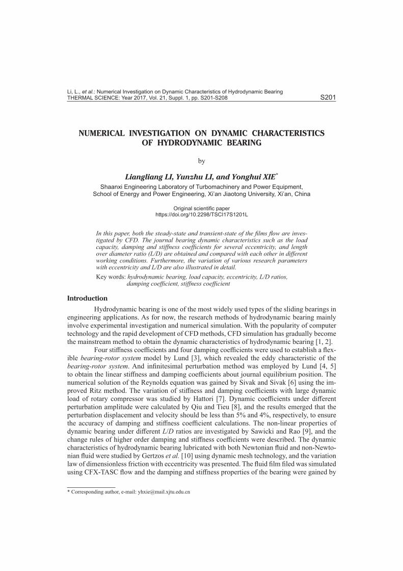
In the common operating eccentricity range of hydrodynamic bearing, the pressure distribution and load capacity of oil film can be obtained under half-Sommerfeld boundary condition by CFD simulation. Figure 1 shows the load capacity and the attitude angle for sev-eral eccentricity in the range of [0.2, 0.7].With the increase of eccentricity, the hydrodynamic effect in wedge becomes more and more obvious and the maximum bearing capacity shows a tendency of accelerated increase. It is observed that the attitude angle approximately approach-es 90° when the eccentricity is closed to zero. And the attitude angle decreases rapidly with the eccentricity. Results extracted in fig. 1 illustrate that the convergent wedge decreases gradually and moves toward the minimum film thickness direction, and the load center moves in the same direction, resulting in a gradual decline of the attitude angle.
0.2 0.3 0.4 0.5 0.6 0.7
5
10
15
20
25
30
35
40
Load
cap
acity
, [kN
]
Eccentricity ratio
Load capacity
0.2 0.3 0.4 0.5 0.6 0.7
50
55
60
65
70
75
80
Attit
ude
angl
e, [d
eg]
Eccentricity ratio
Attitude angle
Figure 1. The influence of eccentricity on load capacity and attitude angle
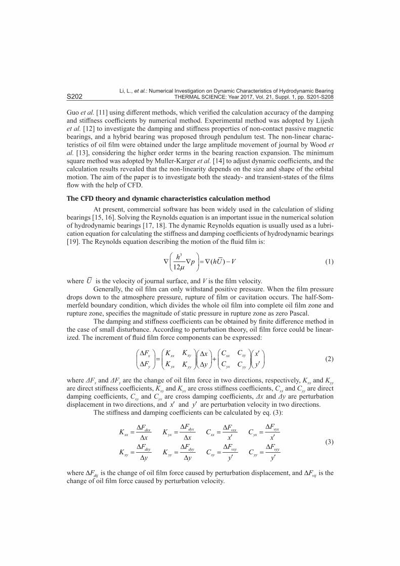
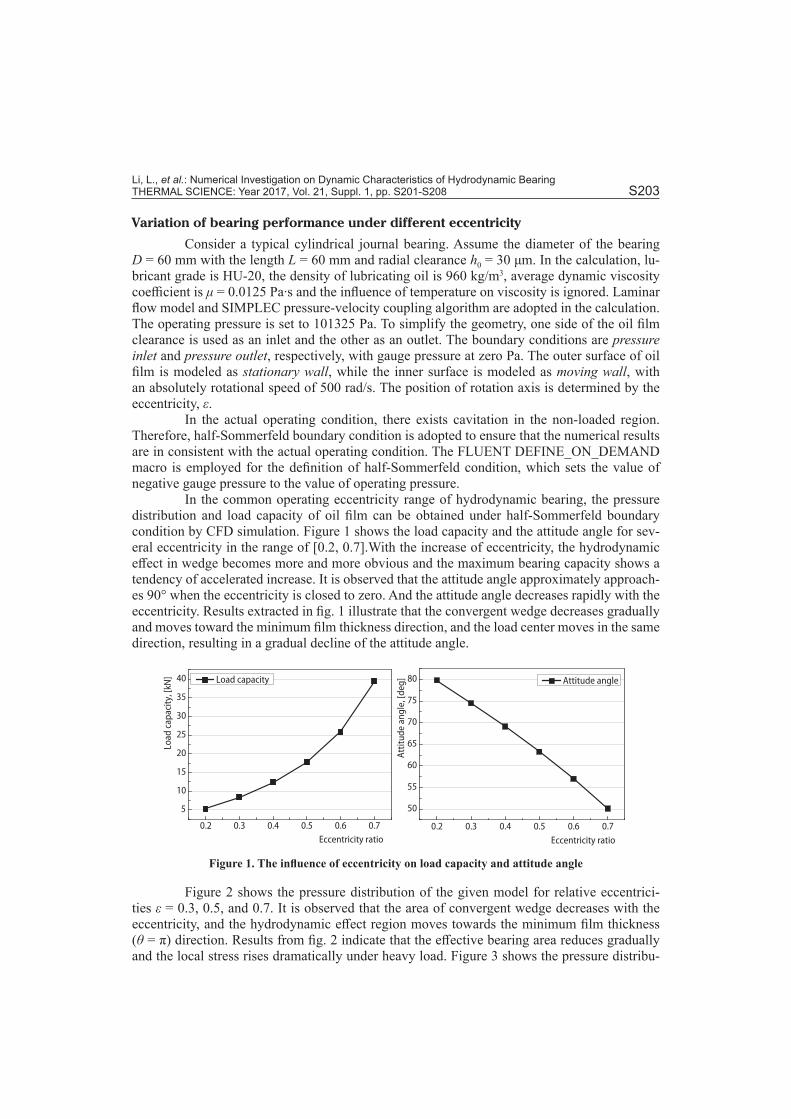
Figure 2 shows the pressure distribution of the given model for relative eccentrici-ties ε = 0.3, 0.5, and 0.7. It is observed that the area of convergent wedge decreases with the eccentricity, and the hydrodynamic effect region moves towards the minimum film thickness (θ = π) direction. Results from fig. 2 indicate that the effective bearing area reduces gradually and the local stress rises dramatically under heavy load. Figure 3 shows the pressure distribu-
Li, L., et al.: Numerical Investigation on Dynamic Characteristics of Hydrodynamic Bearing S204 THERMAL SCIENCE: Year 2017, Vol. 21, Suppl. 1, pp. S201-S208
tion in half-Sommerfeld boundary condition, and the results are consistent with the positive pressure area in fig 2.
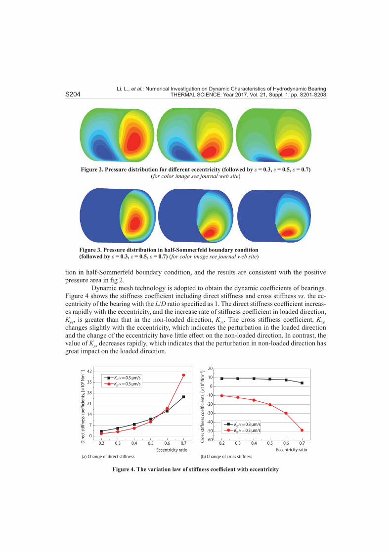
Dynamic mesh technology is adopted to obtain the dynamic coefficients of bearings. Figure 4 shows the stiffness coefficient including direct stiffness and cross stiffness vs. the ec-centricity of the bearing with the L/D ratio specified as 1. The direct stiffness coefficient increas-es rapidly with the eccentricity, and the increase rate of stiffness coefficient in loaded direction, Kyy, is greater than that in the non-loaded direction, Kxx. The cross stiffness coefficient, Kxy, changes slightly with the eccentricity, which indicates the perturbation in the loaded direction and the change of the eccentricity have little effect on the non-loaded direction. In contrast, the value of Kyx decreases rapidly, which indicates that the perturbation in non-loaded direction has great impact on the loaded direction.
Figure 2. Pressure distribution for different eccentricity (followed by ε = 0.3, ε = 0.5, ε = 0.7) (for color image see journal web site)
Figure 3. Pressure distribution in half-Sommerfeld boundary condition (followed by ε = 0.3, ε = 0.5, ε = 0.7) (for color image see journal web site)
(a) (b)
0.2 0.3 0.4 0.5 0.6 0.7
0
7
14
21
28
35
42
Dire
ct st
iffne
ss c
oeffi
cien
ts, [
×10
8 Nm
−1 ]
Cros
s stiff
ness
coe
ffici
ents
, [×
108 N
m−
1 ]
Eccentricity ratio
Kxx v = 0.3 μm/sKyy v = 0.3 μm/s
0.2 0.3 0.4 0.5 0.6 0.7-60
-50
-40
-30
-20
-10
0
10
20
Eccentricity ratio
Change of direct stiffness Change of cross stiffness
Kxy v = 0.3 μm/sKxy v = 0.3 μm/s
Figure 4. The variation law of stiffness coefficient with eccentricity
Li, L., et al.: Numerical Investigation on Dynamic Characteristics of Hydrodynamic Bearing THERMAL SCIENCE: Year 2017, Vol. 21, Suppl. 1, pp. S201-S208 S205
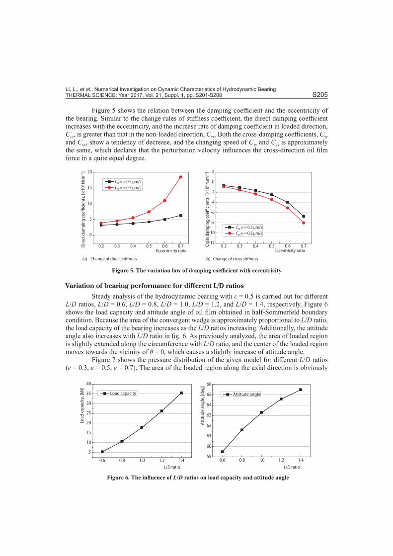
Figure 5 shows the relation between the damping coefficient and the eccentricity of the bearing. Similar to the change rules of stiffness coefficient, the direct damping coefficient increases with the eccentricity, and the increase rate of damping coefficient in loaded direction, Cyy, is greater than that in the non-loaded direction, Cxx. Both the cross-damping coefficients, Cxy and Cyx, show a tendency of decrease, and the changing speed of Cxy and Cyx is approximately the same, which declares that the perturbation velocity influences the cross-direction oil film force in a quite equal degree.
0.2 0.3 0.4 0.5 0.6 0.7
0
5
10
15
20
0.2 0.3 0.4 0.5 0.6 0.7-12
-10
-8
-6
-4
-2
0
2
(a) (b)
Eccentricity ratio Eccentricity ratio
Change of direct stiffness Change of cross stiffness
Dire
ct d
ampi
ng c
oeffi
cien
ts, [
×10
6 Nsm
−1 ]
Cros
s dam
ping
coe
ffici
ents
, [×
106 N
sm−
1 ]
Cxx v = 0.3 μm/sCyy v = 0.3 μm/s
Cxy v = 0.3 μm/sCyx v = 0.3 μm/s
Figure 5. The variation law of damping coefficient with eccentricity
Variation of bearing performance for different L/D ratios
Steady analysis of the hydrodynamic bearing with ε = 0.5 is carried out for different L/D ratios, L/D = 0.6, L/D = 0.8, L/D = 1.0, L/D = 1.2, and L/D = 1.4, respectively. Figure 6 shows the load capacity and attitude angle of oil film obtained in half-Sommerfeld boundary condition. Because the area of the convergent wedge is approximately proportional to L/D ratio, the load capacity of the bearing increases as the L/D ratios increasing. Additionally, the attitude angle also increases with L/D ratio in fig. 6. As previously analyzed, the area of loaded region is slightly extended along the circumference with L/D ratio, and the center of the loaded region moves towards the vicinity of θ = 0, which causes a slightly increase of attitude angle.
Figure 7 shows the pressure distribution of the given model for different L/D ratios (ε = 0.3, ε = 0.5, ε = 0.7). The area of the loaded region along the axial direction is obviously
0.6 0.8 1.0 1.2 1.4
5
10
15
20
25
30
35
40
Load
cap
acity
, [kN
]
L/D ratio L/D ratio
Load capacity
0.6 0.8 1.0 1.2 1.459
60
61
62
63
64
65
66
Attit
ude
angl
e, [d
eg]
Attitude angle
Figure 6. The influence of L/D ratios on load capacity and attitude angle
Li, L., et al.: Numerical Investigation on Dynamic Characteristics of Hydrodynamic Bearing S206 THERMAL SCIENCE: Year 2017, Vol. 21, Suppl. 1, pp. S201-S208
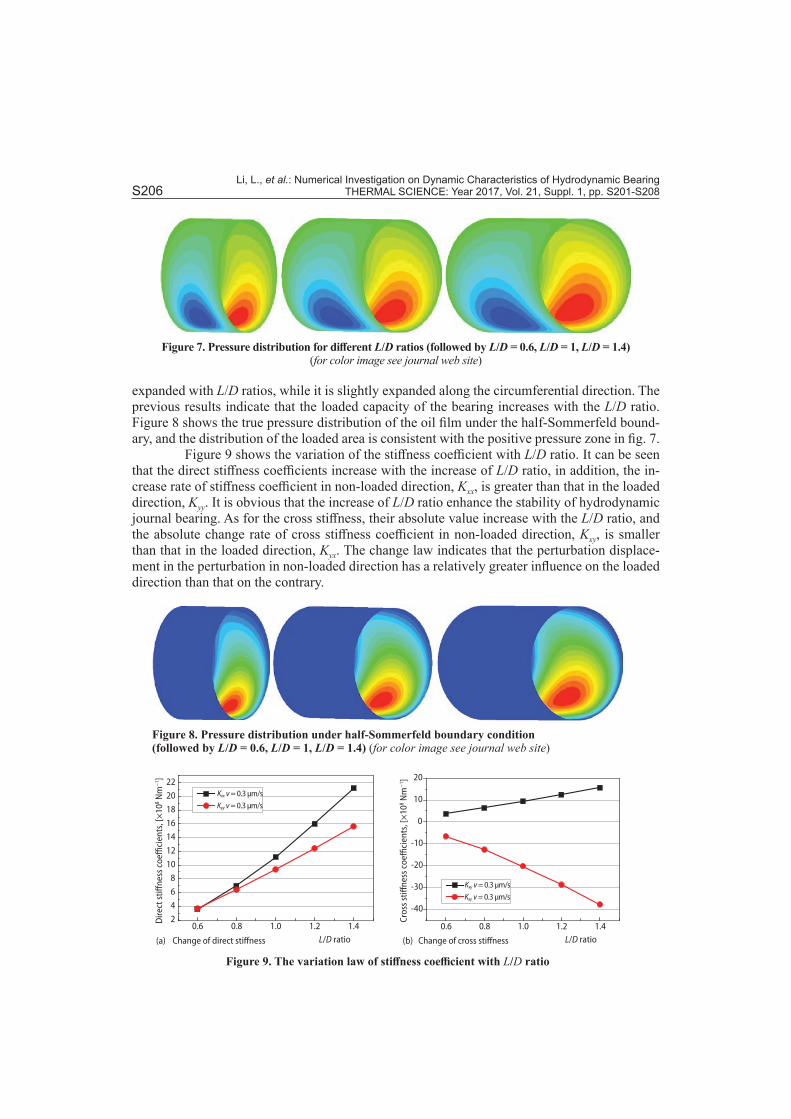
expanded with L/D ratios, while it is slightly expanded along the circumferential direction. The previous results indicate that the loaded capacity of the bearing increases with the L/D ratio. Figure 8 shows the true pressure distribution of the oil film under the half-Sommerfeld bound-ary, and the distribution of the loaded area is consistent with the positive pressure zone in fig. 7.
Figure 9 shows the variation of the stiffness coefficient with L/D ratio. It can be seen that the direct stiffness coefficients increase with the increase of L/D ratio, in addition, the in-crease rate of stiffness coefficient in non-loaded direction, Kxx, is greater than that in the loaded direction, Kyy. It is obvious that the increase of L/D ratio enhance the stability of hydrodynamic journal bearing. As for the cross stiffness, their absolute value increase with the L/D ratio, and the absolute change rate of cross stiffness coefficient in non-loaded direction, Kxy, is smaller than that in the loaded direction, Kyx. The change law indicates that the perturbation displace-ment in the perturbation in non-loaded direction has a relatively greater influence on the loaded direction than that on the contrary.
Figure 7. Pressure distribution for different L/D ratios (followed by L/D = 0.6, L/D = 1, L/D = 1.4) (for color image see journal web site)
Figure 8. Pressure distribution under half-Sommerfeld boundary condition (followed by L/D = 0.6, L/D = 1, L/D = 1.4) (for color image see journal web site)
0.6 0.8 1.0 1.2 1.42
4
6
8
10
12
14
16
18
20
22
0.6 0.8 1.0 1.2 1.4
-40
-30
-20
-10
0
10
20
L/D ratio L/D ratio
Kxx v = 0.3 μm/s
Kyy v = 0.3 μm/s
Kxy v = 0.3 μm/s
Kxy v = 0.3 μm/s
Dire
ct st
iffne
ss c
oeffi
cien
ts, [
×10
8 Nm
−1 ]
Cros
s stiff
ness
coe
ffici
ents
, [×
108 N
m−
1 ]
(a) (b) Change of direct stiffness Change of cross stiffness
Figure 9. The variation law of stiffness coefficient with L/D ratio
Li, L., et al.: Numerical Investigation on Dynamic Characteristics of Hydrodynamic Bearing THERMAL SCIENCE: Year 2017, Vol. 21, Suppl. 1, pp. S201-S208 S207
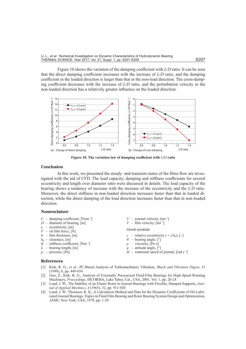
Figure 10 shows the variation of the damping coefficient with L/D ratio. It can be seen that the direct damping coefficient increases with the increase of L/D ratio, and the damping coefficient in the loaded direction is larger than that in the non-load direction. The cross-damp-ing coefficient decreases with the increase of L/D ratio, and the perturbation velocity in the non-loaded direction has a relatively greater influence on the loaded direction.
0.6 0.8 1.0 1.2 1.40
2
4
6
8
10
12
14
16
0.6 0.8 1.0 1.2 1.4
-7
-6
-5
-4
-3
-2
-1
0
L/D ratio L/D ratio
Dire
ct d
ampi
ng c
oeffi
cien
ts, [
×10
6 Nsm
−1 ]
Cros
s dam
ping
coe
ffici
ents
, [×
106 N
sm−
1 ]
Cxx v = 0.3 μm/s
Cyy v = 0.3 μm/s
Cxy v = 0.3 μm/s
Cyx v = 0.3 μm/s
(a) (b) Change of direct damping Change of cross damping
Figure 10. The variation law of damping coefficient with L/D ratio
Conclusion
In this work, we presented the steady- and transient-states of the films flow are inves-tigated with the aid of CFD. The load capacity, damping and stiffness coefficients for several eccentricity and length over diameter ratio were discussed in details. The load capacity of the bearing shows a tendency of increase with the increase of the eccentricity and the L/D ratio. Moreover, the direct stiffness in non-loaded direction increases faster than that in loaded di-rection, while the direct damping of the load direction increases faster than that in non-loaded direction.
Nomenclature
C – damping coefficient, [Nsm–1]D – diameter of bearing, [m]e – eccentricity, [m]F – oil film force, [N]h – film thickness, [m]h0 – clearance, [m]K – stiffness coefficient, [Nm–1]L – bearing length, [m]p – pressure, [Pa]
U – journal velocity, [ms–1]V – film velocity, [ms–1]
Greek symbols
ε – relative eccentricity ( = e/h0), [–]θ – bearing angle, [°]μ – viscosity, [Pa·s]φ – attitude angle, [°]Ω – rotational speed of journal, [rad s–1]
References[1] Kirk, R. G., et al., PC-Based Analysis of Turbomachinery Vibration, Shock and Vibration Digest, 31
(1999), 6, pp. 449-454[2] Guo, Z., Kirk, R. G., Analysis of Externally Pressurized Fluid-Film Bearings for High-Speed Rotating
Machinery, Proceedings, ISCORMA, Lake Tahor, Cal., USA, 2001, Vol. 1, pp. 20-24[3] Lund, J. W., The Stability of an Elastic Rotor in Journal Bearings with Flexible, Damped Supports, Jour-
nal of Applied Mechnics, 4 (1965), 32, pp. 911-920[4] Lund, J. W., Thomsen, K. K., A Calculation Method and Data for the Dynamic Coefficients of Oil-Lubri-
cated Journal Bearings, Topics in Fluid Film Bearing and Rotor Bearing System Design and Optimization, ASME, New York, USA, 1978, pp. 1-28
Li, L., et al.: Numerical Investigation on Dynamic Characteristics of Hydrodynamic Bearing S208 THERMAL SCIENCE: Year 2017, Vol. 21, Suppl. 1, pp. S201-S208
[5] Lund, J. W., Review of the Concept of Dynamic Coefficients for Fluid Film Journal Bearings, ASME J. Tribol, 109 (1987), 1, pp. 37-41
[6] Sivak, B., Sivak, M., The Numerical Solution of the Reynolds Equation by a Modified Ritz Method, Wear, 72 (1981), 3, pp. 371-376
[7] Hattori, H., Dynamic Analysis of a Rotor-Journal Bearing System with Large Dynamic Loads: Stiffness and Damping Coefficient Variations in Bearing Oil Films, Jsme International Journal, 36 (2008), 2, pp. 251-257
[8] Qiu, Z. L., Tieu, A. K., The Effect of Perturbation Amplitudes on Eight Force Coefficients of Journal Bearings, Tribology Transactions, 39 (1996), 2, pp. 469-475
[9] Sawicki, J. T., Rao, T. A., Nonlinear Model for Prediction of Dynamic Coefficients in a Hydrodynamic Journal Bearing, International Journal of Rotating Machinery, 10 (2004), 6, pp. 507-513
[10] Gertzos, K. P., et al., CFD Analysis of Journal Bearing Hydrodynamic Lubrication by Bingham Lubricant, Tribology International, 41 (2008), 12, pp. 1190-1204
[11] Guo, Z., et al., Application of CFD Analysis for Rotating Machinery: Part 1–Hydrodynamic, Hydrostatic Bearings and Squeeze Film Damper, Proceedings, ASME Turbo Expo 2003, Collocated with the 2003 International Joint Power Generation Conference. American Society of Mechanical Engineers, Atlanta, Geo., USA, pp. 651-659, 2003
[12] Lijesh, K.P., et al., Stiffness and Damping Coefficients for Rubber Mounted Hybrid Bearing, Lubrication Science, 26 (2014), 5, pp. 301-314
[13] Wood, K. L., et al., A Nonlinear Dynamic Model with Confidence Bounds for Hydrodynamic Bearings, Journal of Tribology, 120 (1998), 3, pp. 595-604
[14] Muller-Karger, C. M., et al., Derivation of Hydrodynamic Bearing Coefficients Using the Minimum Square Method, Journal of Tribology, 119 (1997), 4, pp. 802-807
[15] Makino, T., Mori, I. I., Entry Flow and Pressure Jump in Submerged Multi-Pad Bearings and Grooved Bearings, Journal of Tribology, 114 (1992), 2, pp. 370-378
[16] Keogh, P. S., On the Dynamic Thermal State in a Hydrodynamic Bearing with a Whirling Journal Using CFD Techniques, Journal of Tribology, 118 (1996), 2, pp. 356-363
[17] Pinkus, O., et al., Theory of Hydrodynamic Lubrication, McGraw-Hill, New York, USA, 1961[18] Nicholas, J. C., et al., Stiffness and Damping Coefficients for the Five-Pad Tilting-Pad Bearing, ASLE
Transactions, 22 (1979), 2, pp. 113-124[19] Ghosh, M. K., et al., Steady-State and Dynamic Behaviour of Multi-Rrecess Hybrid Oil Journal Bearings,
Journal of Mechanical Engineering Science, 21 (1979), 5, pp. 345-351
Paper submitted: March 10, 2017Paper revised: May 1, 2017Paper accepted: May 26, 2017
© 2017 Society of Thermal Engineers of SerbiaPublished by the Vinča Institute of Nuclear Sciences, Belgrade, Serbia.
This is an open access article distributed under the CC BY-NC-ND 4.0 terms and conditions