Embed Size (px)
Citation preview
Numerical modelling of wave-current loading on offshore jacket structures
A.C. Mendes l , J.A. Kolodziej & H. J.D. Correia ' ' Universidade da Beira Interior, Laboratory of Fluid Mechanics, 6200 CovilhZ, Portugal. Institute of Applied Mechanics, Technical University of Poznan, 60-965
Poznan, Poland.
Abstract
In this paper we obtain theoretical predictions of the environmental loading induced upon an offshore structure. The numerical predictions of base-shear and overturning moment that are herein presented concern a four-legged jacket structure scaled-down from a realistic offshore platform. The methodology that has been used in the determination of the hydrodynamic loading is based on the generalized Morison formula, which incorporates the contributions arising from the waves and a uniform current. The water-particle kinematics has been assessed by means of linear wave theory. The selected inertia and drag coefficients are the ones commonly utilized in the design practice of jacket platforms.
1 Introduction
Water waves induce important gradients of velocity and pressure within the fluid beneath the ocean surface and this is at the origin of significant forces exerted upon immersed structures. These forces need to be evaluated as accurately as possible if a marine structure is to be designed. Design and safe operation of offshore structures require in fact a clear understanding of the fluid-structure interactions, especially the ones occurring in extreme sea conditions. Efthymiou & Graham [ I ] tackle this issue in the context of fixed structures. The common practice in the design of such offshore platforms includes theoretical studies conducted by means of either a deterministic or a stochastic approach, whose predictions need later on to be confirmed with the help of experimental tests. In
Transactions on the Built Environment vol 71, © 2004 WIT Press, www.witpress.com, ISSN 1743-3509
86 Fluid Structure Interaction II
this task emphasis has been placed on carefully designed field experiments and equally on the use of large-scale experimental facilities. Significant advances have been achieved in this domain (see Chaplin [2]), using essentially experiments conducted at large-scale.
In this paper we focus on the theoretical study of the hydrodynamics of a jacket platform, subjected to external loading induced by waves and a current. The model structure is a four-legged tubular structure scaled-down from a realistic offshore platform. The prototype is 89.6 m high, from which 67.2 m are underwater. The original physical model, at a scale 1:28, has been subjected to an extensive experimental investigation earlier reported by Mendes et al. [3]. Numerical predictions of the resultant force and overturning moment are now presented for that same structure. The wave-current characteristics adopted as design environmental conditions are the following ones, corresponding to three extreme sea states: a) significant wave height H = 5.6 m, wave period T = 8 sec; b) H = 14 m, T = 14 sec; c) H = 14 m, T = 14 sec and uniform current velocity U = 2 mlsec.
The methodology used in the determination of the environmental loading is based on the generalized Morison formula, which includes the combined contributions arising from waves and from a uniform current. The water-particle kinematics has been assessed by means of linear wave theory. Hydrodynamic coefficients employed to characterize inertia and drag forces are those commonly utilized in designing this type of structures. The results herein presented concern the horizontal and vertical components of the resultant hydrodynamic force acting upon the structure, as well as the moment about its base.
2 Statement of the problem
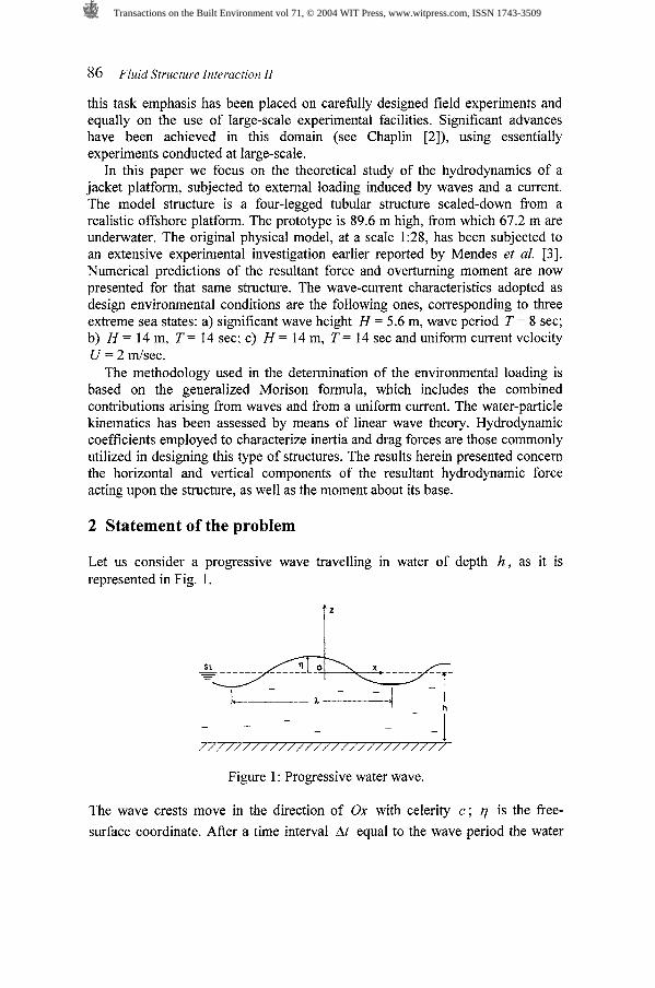
Let us consider a progressive wave travelling in water of depth h , as it is represented in Fig. 1.
Figure 1 : Progressive water wave.
The wave crests move in the direction of Ox with celerity c ; q is the free- surface coordinate. After a time interval At equal to the wave period the water
Transactions on the Built Environment vol 71, © 2004 WIT Press, www.witpress.com, ISSN 1743-3509
Fluid Structure Interaction I1 87
surface reaches its initial form, but displaced by one wavelength it . The celerity is then given by c = L I T , T being the wave period.
2.1 Basic assumptions and equations
The physical properties of surface waves may be stated by means of different mathematical models according to certain approximations. We will assume that the seawater is an incompressible and homogeneous fluid, with constant specific
mass p . The principle of mass conservation may then be stated as: V . = 0 ,
where ?(U, v, W) is the fluid velocity in a point of coordinates (X, y, z) . By
further assuming that the properties are constant along Oy , parallel to the wave crests, we may consider the flow as two-dimensional. If the viscosity of the water can also be neglected, the flow is inviscid. Furthermore it will be assumed
that the wave induced motion of the water particles is irrotational: V x = 0 . These assumptions lead to the conclusion that a velocity potential @(X, y, z , t)
exists, from which the flow velocity components may be derived:
The continuity equation may then be formulated as follows:
which is the well-known Laplace equation. The water-particles motion is unsteady, in which case the principle of energy
conservation may be written as:
This is the Lagrange equation, from which the water pressure and surface elevation may be related with the local acceleration of the flow, d@ 1 d t .
2.2 Wave-current model
A number of important simplifications may result from neglecting the kinetic energy term in eqn (3). Airy developed in 1845 a linearised wave theory based in this assumption. The theory was limited to waves of small relative amplitude: AIR << 1. Actually, the maximal heights of the waves generated by the wind in the open sea rarely go above H = 20 to 30m, and its wavelength is normally less than h = 400 m. Even for the bigger waves, the wave steepness stays very small ( H / A << 1). A limiting value for the validity of Linear Theory in restricted
waters has been established by Stokes in 1950: the value of A2 H/h3 must remain small.
Transactions on the Built Environment vol 71, © 2004 WIT Press, www.witpress.com, ISSN 1743-3509
88 Fluid Structure Interaction 11
Laplace equation (2) has a well-known progressive wave solution. If we take into account the effect of a uniform current over depth, flowing with constant velocity U in the same direction as the waves, the global velocity potential under linearised boundary conditions is, following Dean & Dalryrnple [4]:
where A is the amplitude of the waves and T = Ale = 2r /kc is the period. For a
given water depth h , current velocity U and time period T , the wave number k may be obtained from the dispersion relation:
(m - U k)' = gk tanh(kh) ( 5 ) where the wave angular frequency is w = 2 r / T .
On the other hand the coordinate of the free-surface 77 is readily found from eqn (3), stating that a constant atmospheric pressure acts on the fluid surface.
7 = A sin(kx - wt) (6 )
2.3 Water-particle kinematics
The properties of the fluid flow can now be determined from the expression of @ . Let us analyse next the water-particle motion. The velocity components u
and W of the water particles can be obtained, at any point in the fluid domain, directly from eqn (1). For a wave-current field whose potential has been defined in eqn (4), the two velocity components in horizontal and vertical directions are:
I c / The local acceleration of the flow may equally be obtained by simple differentiation of these equations with respect to time. Hence, the flow acceleration components in horizontal and vertical directions have the form:
a x =-- 1 - U/ cosh (kh)
Velocity and acceleration components will be used later on to determine the hydrodynamic loading.
There is also a periodic variation of pressure beneath the waves which may be determined from Lagrange equation (3). It could be shown that the maximum
Transactions on the Built Environment vol 71, © 2004 WIT Press, www.witpress.com, ISSN 1743-3509
Fluid Structure Interaction I1 89
pressure variation occurs at the free surface, and then decays exponentially with depth.
3 Hydrodynamic loading
The design of offshore platforms consists of a certain number of procedures that constitute the common practice in this field. In spite the theoretical determination of the wave-current loading being a difficult task, due primarily to the complexity of the fluid-structure interactions, the hydrodynamic forces acting on offshore jacket platforms are well predicted nowadays.
3.1 The Morison formula
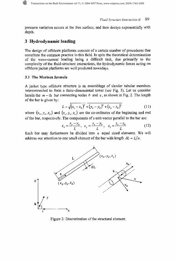
A jacket type offshore structure is an assemblage of slender tubular members interconnected to form a three-dimensional tower (see Fig. 3). Let us consider herein the m - th bar connecting nodes b and e , as shown in Fig. 2. The length of the bar is given by:
where (X,, y,, z, ) and (X,, ye, z,) are the co-ordinates of the beginning and end of the bar, respectively. The components of a unit-vector parallel to the bar are:
Each bar may furthermore be divided into n equal sized elements. We will address our attention to one small element of the bar with length 6L = L/n .
Figure 2: Discretization of the structural element.
Transactions on the Built Environment vol 71, © 2004 WIT Press, www.witpress.com, ISSN 1743-3509
90 Fluid Structure Interaction 11
The size of the structural members in jacket type platforms is small, when compared to the wavelength A of the dominant waves. Consequently, drag forces become significant in this case and, hence, the Morison model may be applied to get accurate predictions of the external forces. The Morison formula has been initially proposed by Morison et al. [ 5 ] , in order to determine the horizontal force that is exerted on a vertical pile under waves. According to Rahrnan [6], the elemental hydrodynamic force acting on a rod element is given by the equation:
where p is the specific mass of water, d is the diameter of the rod, C, is the
drag coefficient and C, is the mass coefficient. The moment of the force 6F about the origin of the co-ordinates system is simply 6M = r X 6F , r being the radius-vector about 0 .
In this eqn (13) the normal velocity v, and acceleration a, of the flow are to be expressed in terms of the wave-current characteristics and time. In agreement with the basic assumptions of the problem, the vector of fluid velocity at the centroid of the structural finite-element in Fig. 2 is equal to:
v=u(x,,y,,z,)i+w(x,,y,,z,)k (14) where i , j , k are unit-vectors parallel to the X, y,z axes, respectively. If
s = sxi + S , j + s,k is the unit-vector in the direction of the rod axis, then the
projection of the velocity vector in the direction of s is: v, = sxu + s,w . Moreover, this velocity vector as expressed on its X, y, z components is equal to:
v, = (S,U + s,w)(sxi + S , j + s,k) (15) The velocity vector perpendicular to the axis of the element is consequently: v , = v - v , , that is
v, = [ U - ( s , u + s , w ) s ~ ] ~ - ( s , u + s , w ) s ~ ~ + [ w - ( s ~ u + s , w ) s , ] ~ (16)
Similarly, the acceleration vector at the centroid of the rod element is equal to: a = a x ( x , , y , , z , ) i + a z ( x , , ~ , > z s ) k (17)
while the projection of this vector in the direction of s is: a, = sxa, + s,a, . This acceleration vector, as expressed on its X, y, z components, values
a, = (s,ax +s ,a , ) ( s , i+s , j+s ,k ) (18)
The acceleration perpendicular to the axis of the element is now equal to: a, = a - a , ,
a , = [ax -(sxax +sza , ) sx] i - ( sxax +s zaz ) s y j+ [a , -(sxax +s,a,)s,]k (19)
The velocity components u and W , as well as acceleration components a,
and a, , have been previously determined from the wave kinematics as described by Airy's theory - eqns (7, 8, 9, 10). It is worth to mention that they need to be expressed in the structure reference frame, usually based on the sea floor.
Transactions on the Built Environment vol 71, © 2004 WIT Press, www.witpress.com, ISSN 1743-3509
Fluid Structure Interaction 11 9 1
3.2 Equivalent forces and moment
To analyse the hydrodynamic forces acting on the structure, the platform may be idealised as a rigid truss or frame system that consists of a number of nodal points interconnected by bars. The general system of external forces is herein reduced to an equivalent set of forces and moment. The forces are here of a distributed type, whose intensity varies in space and time. This distributed system of forces can be replaced by an equivalent system of forces consisting of the resultant force and a resultant moment (see Ross 171).
It is well known fiom the mechanics of a rigid body that, by choosing the point of reduction for any system of applied forces, this system of forces can be replaced by a total force and a total moment. The resultant force is the vector sum of forces acting on the body and does not depend on the particular choice of the reduction point, while the resultant moment, being the sum of moments of all forces with respect to the reduction point, depends on the selection of such point of reduction. In the case of the discrete structure loaded by waves and current, the resultant force and moment acting on the structure are respectively:
where 84, is the force exerted on the jth finite-element belonging to the ith
rod; this elemental force is to be calculated by means of eqn (13). SM, is the
moment of this force with respect to the origin of the co-ordinates system.
3.3 Inertia and drag coefficients
A pioneer work on the experimental determination of the drag and inertia coefficients has been conducted by Keulegan & Carpenter [S], for a cylinder immersed in a stationary-wave field. The proposed coefficients have been quite often used to calculate the hydrodynamic forces defined above. Ever since different experimental approaches have been utilized in order to determine with less uncertainty the values of the hydrodynamic coefficients. Sarpkaya et al. [9] reported experiments with a fixed cylinder placed in an oscillating water-column, originated in a U-tube. A valuable contribution to this has also been given by Chakrabarti [10], who tested a fixed structure in waves and determined its hydrodynamic coefficients as a function of the Keulegan-Carpenter number. The value of the inertia coefficient for uniformly accelerated flow conditions is C, = 2.0. In steady flow conditions C, is dependent on Reynolds number and on the roughness of the cylinder's surface.
When the structure operates in waves and a current, the relevant non- dimensional parameters KC and Re are defined in the following manner:
KC = (UO + ; Re= (UO + D v
(21)
where U, is the amplitude of the wave-induced velocity, U is the velocity of the current and D a characteristic dimension of the structure.
Transactions on the Built Environment vol 71, © 2004 WIT Press, www.witpress.com, ISSN 1743-3509
92 Fluid Structure Interaction 11
More recently experimental decay measurements with an oscillating cylinder have been conducted at large scale, in still water and in current - Chaplin [ l l]. Experimental tests in waves and current carried out in laboratory are not common. Iwagaki et al. 1121 equally tested two vertical cylinders of different size in waves and reverse current. Coefficients CM and C, were then
determined for KC = 0 to 45. The values that were found are not much different from those measured in waves only.
4 A case-study
This section discusses the estimates of horizontal and vertical force components and of the overturning moment that are exerted upon an offshore jacket platform, as a result of the hydrodynamic interaction with regular waves and a uniform current.
4.1 Model structure
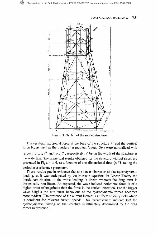
The model structure has been scaled down from a realistic offshore jacket design. The platform is composed of 158 structural members welded at 48 junction nodes. The total height of the structure is 89.6 m, of which 67.2 m is underwater. The base square is 33.6 X 33.6 m and the square at the top is 16.8 X
16.8 m. The four legs have an external diameter D = 1.596 m and 112 mm wall thickness, and the bracing members have an external diameter d = 0.896 m and 70 mm wall thickness. A group of l l vertical risers of diameter 0.896 m extend from top to bottom. Fig. 3 represents the model structure at a scale 1:28.
4.2 Predictions of the theory
A theoretical prediction of the hydrodynamic loading on the platform has been obtained considering three different environmental conditions. These conditions correspond to extreme sea states and are characterized by the following parameters in full scale: a) wave height H = 5.6 m, period T = 8.0 s (no current); b) H = 14.0 m, T = 14.0 s (no current); c) H = 14.0 m, T = 14.0 S, U = 2 rn/s (uniform current velocity).
The wave force has been calculated by using the Morison model in deep water. We have adopted characteristic values for the hydrodynamic coefficients which are basically the ones used in common design practice for this type of platforms: CM = 2.0 and C, = 0.6 t 0.7 . The water-particle kinematics used in the numerical calculations corresponds to Linear Wave Theory. However, the computational model comprises the possibility of calculating velocity and acceleration by means of a 2nd-order Stokes approximation. This enables to evaluate the limitations of Airy's theory when determining the hydrodynamic forces (not reported here).
Transactions on the Built Environment vol 71, © 2004 WIT Press, www.witpress.com, ISSN 1743-3509
Fluid Structure Interaction I1 93
Figure 3: Sketch of the model structure.
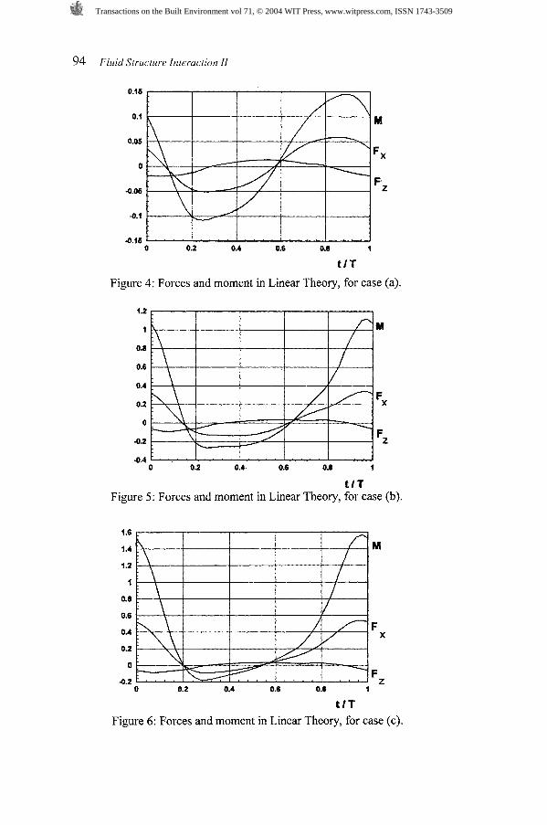
The resultant horizontal force at the base of the structure F, and the vertical force F,, as well as the overturning moment (about Oy ) were normalized with
respect to p g t3 and p g t4 , respectively, t being the width of the structure at the waterline. The numerical results obtained for the structure without risers are presented in Figs. 4 to 6 , as a function of non-dimensional time ( t l ~ ) , taking the period as a reference parameter.
These results put in evidence the non-linear character of the hydrodynamic loading, as it was anticipated by the Morison equation. In Linear Theory the inertia contribution to the wave loading is linear, whereas the drag term is intrinsically non-linear. As expected, the wave-induced horizontal force is of a higher order of magnitude than the force in the vertical direction. For the bigger wave heights the non-linear behaviour of the hydrodynamic forces becomes more evident. The presence of the current induces a uniform velocity field which is dominant for relevant current speeds. This circumstances indicate that the hydrodynamic loading on the structure is ultimately determined by the drag forces in presence.
Transactions on the Built Environment vol 71, © 2004 WIT Press, www.witpress.com, ISSN 1743-3509
94 Fluid Structure Interaction 11
t l T
Figure 4: Forces and moment in Linear Theory, for case (a).
t l T Figure 5: Forces and moment in Linear Theory, for case (b).
t l T
Figure 6: Forces and moment in Linear Theory, for case (c).
Transactions on the Built Environment vol 71, © 2004 WIT Press, www.witpress.com, ISSN 1743-3509
Fluid Structure Interaction I1 95
5 Conclusions
This paper deals with a numerical model for prediction of hydrodynamic loading on jacket platforms under incident regular waves, in the presence of a uniform current. A number of important simplifications may result from neglecting the kinetic energy term in the free-surface condition. A classical linearized wave theory has been developed by Airy based in this assumption. This theory has been used here to calculate the fluid velocities and accelerations. Horizontal and vertical force components, as well as overturning moment acting on the structure were then assessed with the help of Morison equation, for three different sea conditions.
The hydrodynamic forces increase with wave height and with coupled influence of waves and current. A substantial contribution is added to the wave force in the presence of a uniform current. At significant current velocities the overall loading is essentially dominated by drag, which may represent as much as 60% increase in maximum horizontal force depending upon the wave period. The maximum horizontal force in waves and current (case c) is about 2.4 19x 1 o7 N, for the prototype structure considered. Similar conclusions may be drawn for the hydrodynamic moment.
The uncertainty of theoretical predictions of hydrodynamic forces based on Morison model may be easily determined. If inertia and damping coefficients are correctly selected, the wave forces over small structural elements can be accurately estimated. The model predicts well the hydrodynamic loading, except in an intermediate region where the Keulegan-Carpenter number is between 8 and 25. This region corresponds to the situation in which both hydrodynamic coefficients are similar and strongly dependent from flow turbulence and surface roughness. The correlation between our theoretical predictions and experimental measurements earlier obtained in wavetank (see Mendes et al. [3] ) reflects, inevitably, important scale effects.
From the above considerations it appears convenient to conduct a deeper theoretical analysis of the fluid-structure interaction, based on higher-order wave theories, aiming to put in evidence the real non-linearities in extreme sea conditions. We must equally keep in mind that there is an important variation of the immersed parts of the structure at free-surface level, which implies a variation of water-particle kinematics at each structural element position. The computational model must also enable the possibility of including different hydrodynamic coefficients associated with each structural element, as a function of depth and age of the platform. The effect of marine fouling over the structure, consolidated by time, is in fact very important. There are very complete databases of C, and C,, based on laboratory experiments. However, some care must be taken on the extrapolation of these coefficients to the case of a real structure operating at sea. Useful hydrodynamic coefficients for such a situation can be selected from data collected in situ through the years, as a function of KC and Re.
Transactions on the Built Environment vol 71, © 2004 WIT Press, www.witpress.com, ISSN 1743-3509
96 Fluid Structure Interaction 11
Acknowledgements
The authors would like to acknowledge the valuable contribution brought to this research by Prof. John Chaplin, from Southampton University, in England, and also by Dr. Anita Uscilowska and Dr. Roman Starosta, both from Poznan University of Technology, Poland.
References
[ l ] Efthymiou, M. & Graham, C.G., Environmental loading on fixed offshore platforms. Environmental Forces on Offshore Platforms and Their Prediction, ed. Kluwer Academic Publishers: London, 26, pp. 293-320, 1990.
[2] Chaplin, J.R., Hydrodynamic damping of cylinders in still water, in currents and in oscillatory flow. Proc. of the Int. Workshop on Environmental Loading on Offshore Structures, Universidade da Beira Interior: CovilhZ, pp. 6-15, 1997.
[3] Mendes, A.C., Kishev, R. & Kolodziej, J.A., Measurements of hydrodynamic loading on a large-scale jacket structure under waves and current. International Series on Advances in Fluid Mechanics, ed M. Rahman, WIT Press: Southampton, 30, pp. 13-24,200 1.
[4] Dean, R.G. & Dalrymple, R.A., Water Wave Mechanics for Engineers and Scientists, ed. World Scientific: New Jersey, 199 1.
[5] Morison, J.R., O'Brien, M.P., Johnson, J.W. & Schaaf, S.A., The force exerted by surface waves on piles. Petroleum Transactions, AIME , 189, pp. 149-157, 1950.
[6] Rahman, M., Water Waves, Relating Modern Theory to Advanced Engineering Practice, ed. Clarendon Press: Oxford, 1995.
[7] Ross, C.T.F., Computational Methods in Structural Continuum Mechanics, John Wiley & Sons, 1982.
[8] Keulegan, G.H. & Carpenter, L.H., Forces on cylinders and plates in an oscillating fluid. J. of Research of The National Bureau of Standards, 60(5), pp. 423-440, 1958.
[9] Sarpkaya, T., Collins, N.J. & Evans, S.R., Wave forces on rough-walled cylinders at high Reynolds Numbers. Proc. 91h Offshore Technology Conference, Houston, pp. 175-1 84, 1977.
[l01 Chakrabarti, S.K., Inline forces on fixed vertical cylinder in waves. J. Waterway, Port, Coastal and Ocean Division, ASCE, 106, pp. 145-155, 1980.
[ l l ] Chaplin, J.R., Hydrodynamic damping of a cylinder at p=106. Proc. of the TMRIALF End-of-Programme Workshop, Delft, 1999.
[l21 Iwagaki, Y., Asano, T. & Nagai, F., Hydrodynamic forces on a circular cylinder placed in wave-current CO-existing fields. Memoirs of the Faculty ofEngineering, Kyoto University, XLV(l), pp. 11-23, 1983.
Transactions on the Built Environment vol 71, © 2004 WIT Press, www.witpress.com, ISSN 1743-3509