Embed Size (px)
Citation preview

Numerical Study of the Effect of WorkpieceThickness on the Interfacial Behavior of a MoltenAluminum Droplet on a Zinc-coated Steel SheetWon-Ik Cho ( [email protected] )
Bremer Institut für angewandte Strahltechnik https://orcid.org/0000-0002-4047-4230Peer Woizeschke
Research Article
Keywords: Brazing, Numerical Simulation, Aluminum, Zinc-coated steel, Wetting, Interfacial behavior
Posted Date: November 9th, 2021
DOI: https://doi.org/10.21203/rs.3.rs-1013016/v1
License: This work is licensed under a Creative Commons Attribution 4.0 International License. Read Full License
Version of Record: A version of this preprint was published at The International Journal of AdvancedManufacturing Technology on January 20th, 2022. See the published version athttps://doi.org/10.1007/s00170-022-08719-x.
Numerical study of the effect of workpiece thickness on the interfacial behavior of a molten aluminum droplet on a zinc-coated steel sheet Won-Ik Cho1,*, Peer Woizeschke1
1 BIAS – Bremer Institut für angewandte Strahltechnik GmbH, 28359 Bremen, Germany
* E-mail: [email protected], ORCID: 0000-0002-4047-4230.
Abstract In brazing, the interfacial conditions between the molten filler material and the solid workpiece are important, yet
they cannot be observed experimentally. A two-dimensional axisymmetric simulation was conducted to analyze the
behavior of a single droplet of molten aluminum on zinc-coated steel sheet as a simplified brazing process. The
simulation models were verified through a comparison with experimental results in terms of bead shape, zinc
distribution, and molten metal behavior. The results show that Young’s equation was not valid in explaining the
wetting behavior because of the instant solidification. In this respect, the effects of the workpiece thickness and
wetting angle on the bead width were negligible. Two periods of time, namely the times for the temperature
difference and solidification, and their ratio (interface number) were defined to analyze the temperature behavior at
the interface over time as well as the effects of workpiece thickness. The interfacial temperature behaviors tended to
be divided into three regions: linear (or inversely proportional), singular, and convergence. The interface number
converged to a value of one with the increase in the thickness.
Keywords Brazing · Numerical Simulation · Aluminum · Zinc-coated steel · Wetting · Interfacial behavior
1 Introduction
Due to environmental issues, high strength steels, aluminum alloys, magnesium alloys, glass fiber reinforced
thermoplastics, and their hybrid structures have received much attention in the automotive industry for the
light-weight construction of car bodies [1]. Most European car manufacturers use ultra-high-strength hot-stamped
boron steels (UHSS) because these can significantly reduce the car body weight for a relatively low price. For
additional weight reduction, floor, roof, hood, and door parts made of steel can be replaced with aluminum alloys [2].
To do this, it is necessary to secure welding and joining technologies for the dissimilar materials of steel and
aluminum alloy. The methods can be typically divided into mechanical and thermal processes. Unlike mechanical
processes, such as riveting and clinching, thermal processes have the advantage of direct material connection,
relatively high process speeds, and low process costs. However, thermal processes must overcome the differences in
the thermophysical material properties and the limited solubility of dissimilar materials [3]. In particular, the latter
creates intermetallic compounds that degrade the metallurgical, mechanical, and electrical properties of joints. It is
impossible to create a joint with the acceptable properties using conventional welding processes that involve the
excessive melting and mixing of dissimilar metals. For this reason, brazing, in which the joint is formed by melting
only the filler material and not the base material with which it is to be joined, has been proposed as an alternative.
The filler melts at a relatively low temperature and wets the surface of the base material, filling the gap through
capillary action. Due to the relatively low process temperature, the formation of intermetallic compounds is reduced,
meaning the method can be successfully applied to the welding and joining of dissimilar metals [4]. In addition,
brazing can obtain a smoother surface than conventional welding processes. Therefore, it is actively applied to the
automotive industry where sheet metal joining is required, especially for car parts such as tailgates, roof joints, and C
columns, for which visual seam quality is important because they are externally visible. Various brazing processes
exist, but the automotive industry requires processes that minimize the thermal effect for aesthetic reasons as well as
high mechanical properties. For this reason, laser brazing, which can minimize the size of a heat source and facilitate
easy energy control, is being applied in the automobile industry. Laser brazing is known to offer good joint properties
for dissimilar materials as it has a faster processing speed and a small heat affected area [5].
The most important condition in the brazing process is the ability of the molten filler material to spread well over the
base material. However, naturally grown oxide layers on the aluminum surface interfere with this wetting [6]. Flux
can be applied to solve this problem but, since most flux is toxic and corrosive, it has a disadvantage in that it must
be removed after brazing. On the other hand, in the case of zinc-coated steels, molten aluminum can be easily wetted
on the surface without flux [7]. The improved wetting due to zinc coating is also observed in other molten metals [8,
9, 10]. Also, in the laser-MIG hybrid process, zinc coating showed favorable results in relation to wetting [11]. An
experimental model system was designed to observe the behavior of an AlSi12 droplet on the surface of a
zinc-coated steel sheet [12]. The results showed that the galvanization types (electro and hot-dip) did not affect the
wetting, and the zinc accumulated at the side end of the bead. The zinc accumulation is also reported for other metals,
and it is may be caused by the molten zinc being pushed laterally by the kinetic energy of the fallen droplet [13].
Similar results were also expected based on numerical simulation [14]. Computational fluid dynamics (CFD)
simulation results showed that molten zinc was laterally pushed as the molten metal propagated to the side. However,
the simulation result had a problem of overestimating the bead size.
This study attempts to improve on the previous one [14]. Conditions similar to the experiment are applied in a
simulation. Hereby, the height at which droplet begins to fall and the convective and radiative heat losses are
considered. In addition, in order to improve the accuracy of the bead shape estimation, the measured weight of the
droplet is used to calculate the droplet size set in the simulation. The model used in the simulation is verified by
comparing it with the experimental results for the bead shape, zinc distribution, and molten metal behavior. Using the
verified model, the effects of workpiece thickness are elucidated by using the interfacial temperature behavior, and
for this purpose, two periods of time and their ratio are defined and used to characterize the process.
2 Methodology
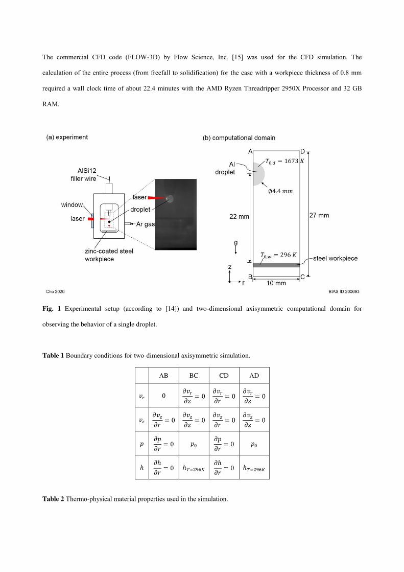
Fig. 1(a) shows the experimental model system (in-house developed system, BIAS GmbH, Germany) used in this
study. This device generates a single droplet by melting a wire with a laser and allowing it to freefall onto the
workpiece. The experiment was performed in a process chamber filled with argon at room temperature. AlSi12
aluminum filler wire was fed vertically through a nozzle, and a laser beam (TruDisk8002, Trumpf GmbH, Germany)
was irradiated horizontally through a window. The wire melted by the laser produced a droplet at a height of 22 mm,
freefalling onto a zinc-coated steel sheet (0.8 mm, DX56 + Z140) at room temperature (23°C). A high-speed camera
(Phantom V5.1, Vision Research Inc., USA) was used to observe the behavior of the droplet colliding with and
wetting the workpiece. A two-color pyrometer system (IGAR-12 LO, IMPAC Infrared GmbH, Germany) was used to
measure the temperature, and the droplet temperature was about 1400 °C. The weight of the measured droplet was
110 mg on average.
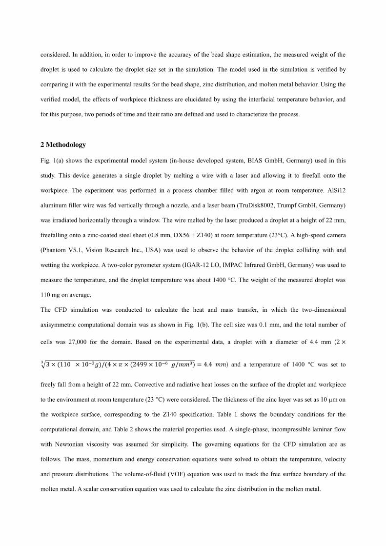
The CFD simulation was conducted to calculate the heat and mass transfer, in which the two-dimensional
axisymmetric computational domain was as shown in Fig. 1(b). The cell size was 0.1 mm, and the total number of
cells was 27,000 for the domain. Based on the experimental data, a droplet with a diameter of 4.4 mm (2 ×√3 × (110 × 10−3𝑔)/(4 × 𝜋 × (2499 × 10−6 𝑔/𝑚𝑚3)3 = 4.4 𝑚𝑚) and a temperature of 1400 °C was set to
freely fall from a height of 22 mm. Convective and radiative heat losses on the surface of the droplet and workpiece
to the environment at room temperature (23 °C) were considered. The thickness of the zinc layer was set as 10 µm on
the workpiece surface, corresponding to the Z140 specification. Table 1 shows the boundary conditions for the
computational domain, and Table 2 shows the material properties used. A single-phase, incompressible laminar flow
with Newtonian viscosity was assumed for simplicity. The governing equations for the CFD simulation are as
follows. The mass, momentum and energy conservation equations were solved to obtain the temperature, velocity
and pressure distributions. The volume-of-fluid (VOF) equation was used to track the free surface boundary of the
molten metal. A scalar conservation equation was used to calculate the zinc distribution in the molten metal.
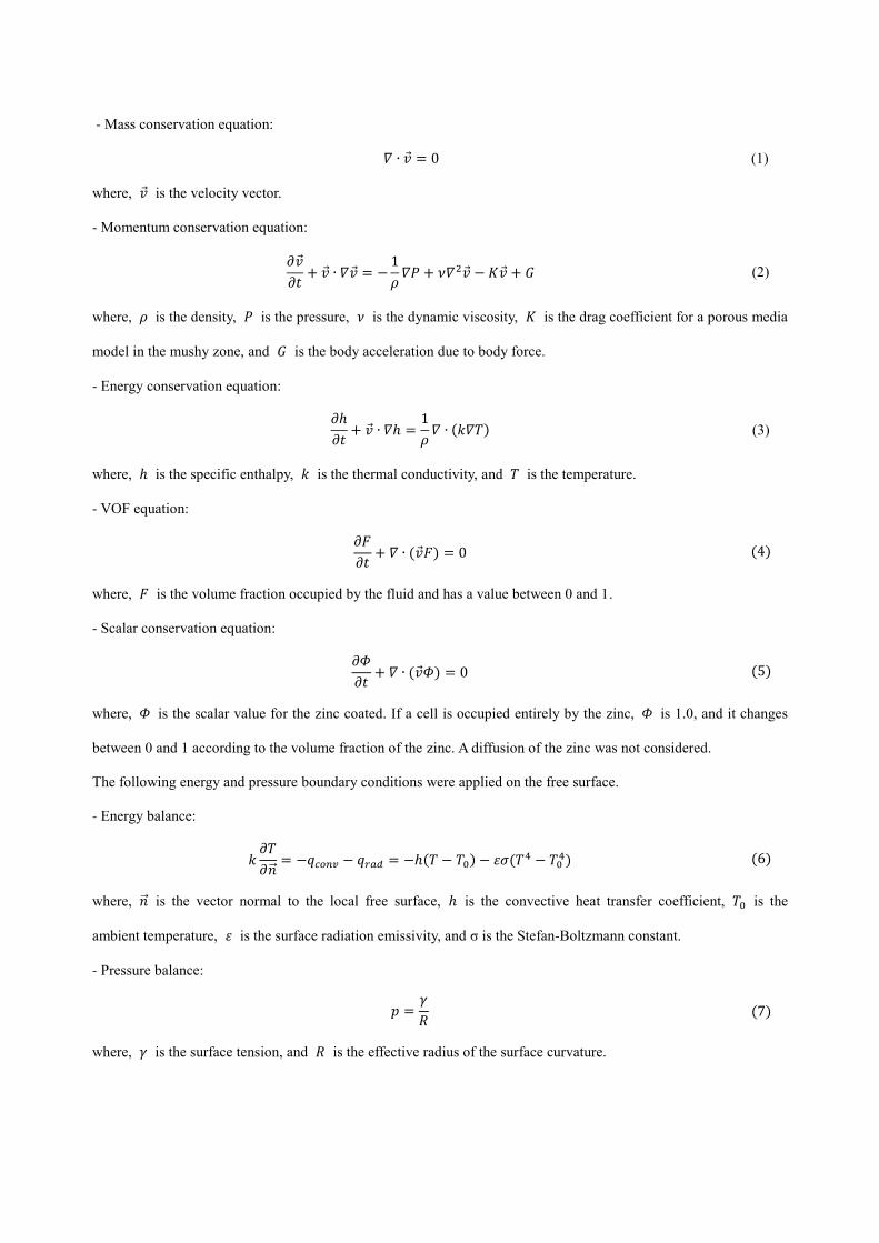
- Mass conservation equation: 𝛻 ∙ �⃗� = 0 (1)
where, �⃗� is the velocity vector.
- Momentum conservation equation: 𝜕�⃗�𝜕𝑡 + �⃗� ∙ 𝛻�⃗� = − 1𝜌 𝛻𝑃 + 𝜈𝛻2�⃗� − 𝐾�⃗� + 𝐺 (2)
where, 𝜌 is the density, 𝑃 is the pressure, 𝜈 is the dynamic viscosity, 𝐾 is the drag coefficient for a porous media
model in the mushy zone, and 𝐺 is the body acceleration due to body force.
- Energy conservation equation: 𝜕ℎ𝜕𝑡 + �⃗� ∙ 𝛻ℎ = 1𝜌 𝛻 ∙ (𝑘𝛻𝑇) (3)
where, ℎ is the specific enthalpy, 𝑘 is the thermal conductivity, and 𝑇 is the temperature.
- VOF equation: 𝜕𝐹𝜕𝑡 + 𝛻 ∙ (�⃗�𝐹) = 0 (4)
where, 𝐹 is the volume fraction occupied by the fluid and has a value between 0 and 1.
- Scalar conservation equation: 𝜕𝛷𝜕𝑡 + 𝛻 ∙ (�⃗�𝛷) = 0 (5)
where, 𝛷 is the scalar value for the zinc coated. If a cell is occupied entirely by the zinc, 𝛷 is 1.0, and it changes
between 0 and 1 according to the volume fraction of the zinc. A diffusion of the zinc was not considered.
The following energy and pressure boundary conditions were applied on the free surface.
- Energy balance:
𝑘 𝜕𝑇𝜕�⃗⃗� = −𝑞𝑐𝑜𝑛𝑣 − 𝑞𝑟𝑎𝑑 = −ℎ(𝑇 − 𝑇0) − 𝜀𝜎(𝑇4 − 𝑇04) (6)
where, �⃗⃗� is the vector normal to the local free surface, ℎ is the convective heat transfer coefficient, 𝑇0 is the
ambient temperature, 𝜀 is the surface radiation emissivity, and σ is the Stefan-Boltzmann constant.
- Pressure balance: 𝑝 = 𝛾𝑅 (7)
where, 𝛾 is the surface tension, and 𝑅 is the effective radius of the surface curvature.
The commercial CFD code (FLOW-3D) by Flow Science, Inc. [15] was used for the CFD simulation. The
calculation of the entire process (from freefall to solidification) for the case with a workpiece thickness of 0.8 mm
required a wall clock time of about 22.4 minutes with the AMD Ryzen Threadripper 2950X Processor and 32 GB
RAM.
Fig. 1 Experimental setup (according to [14]) and two-dimensional axisymmetric computational domain for
observing the behavior of a single droplet.
Table 1 Boundary conditions for two-dimensional axisymmetric simulation.
AB BC CD AD
𝑣𝑟 0 𝜕𝑣𝑟𝜕𝑧 = 0
𝜕𝑣𝑟𝜕𝑟 = 0 𝜕𝑣𝑟𝜕𝑧 = 0
𝑣𝑧 𝜕𝑣𝑧𝜕𝑟 = 0
𝜕𝑣𝑧𝜕𝑧 = 0 𝜕𝑣𝑧𝜕𝑟 = 0
𝜕𝑣𝑧𝜕𝑧 = 0
𝑝 𝜕𝑝𝜕𝑟 = 0 𝑝0
𝜕𝑝𝜕𝑟 = 0 𝑝0
ℎ 𝜕ℎ𝜕𝑟 = 0 ℎ𝑇=296𝐾
𝜕ℎ𝜕𝑟 = 0 ℎ𝑇=296𝐾
Table 2 Thermo-physical material properties used in the simulation.
Property Value
droplet
Density
2596 kg/m3 (solid) 2499 kg/m3 (liquid)
Thermal conductivity
95.4 Wm K (solid) 66.8 Wm K (liquid)
Viscosity 1.5 × 10⁻³ kg/m s
Surface tension* 0.871 J/m2 [16]
Surface tension gradient* −1.55 × 10⁻⁴ J/m2 K [16]
Specific heat
1.161 × 10³ J/kg K (solid) 1.187 × 10³ J/kg K (liquid)
Latent heat of fusion 4.89 × 10⁵ J/kg
Solidus temperature 790 K
Liquidus temperature 841 K
workpiece
Density × specific heat 5.4 × 10⁶ kg/m s2 K
Thermal conductivity 22.6 Wm K
Convective heat transfer coefficient 20 W/m2 K
Emissivity 0.4
*Pure aluminum.
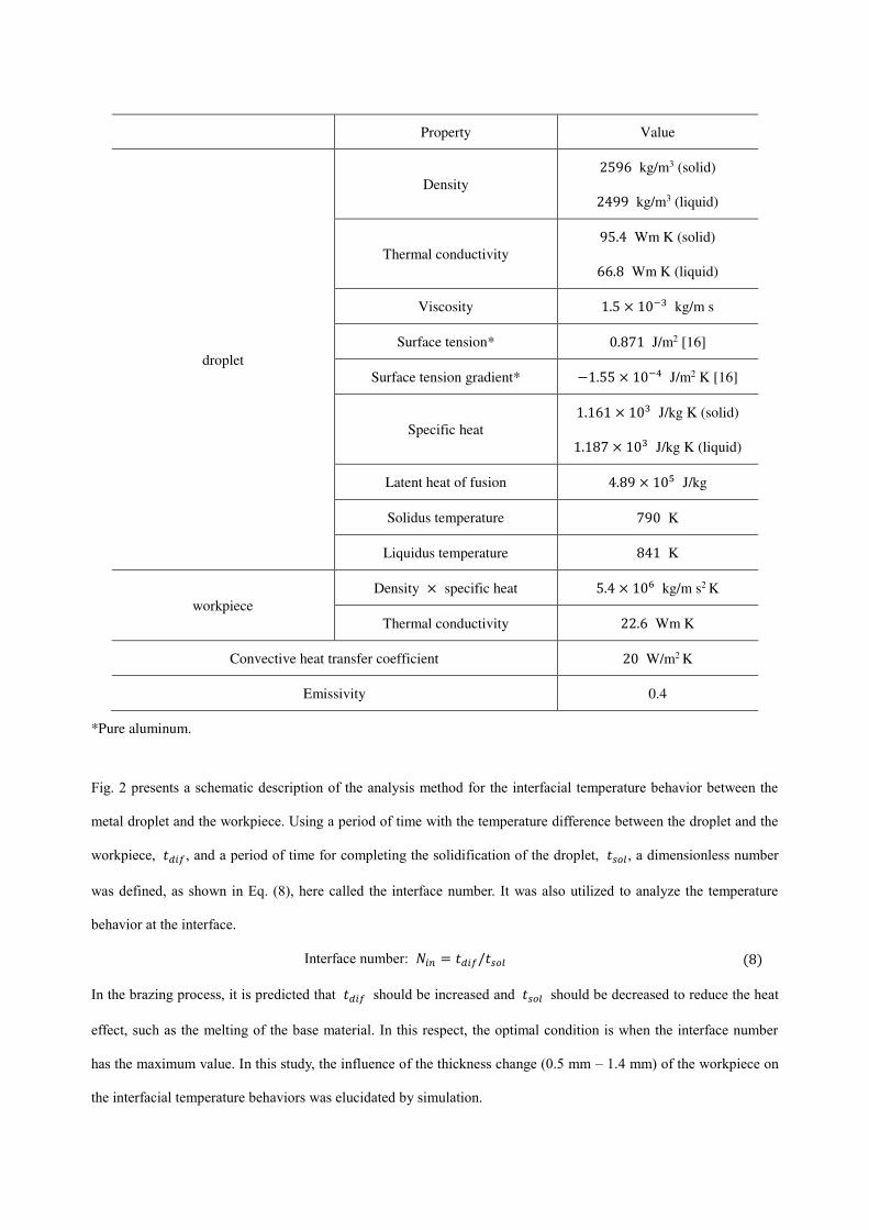
Fig. 2 presents a schematic description of the analysis method for the interfacial temperature behavior between the
metal droplet and the workpiece. Using a period of time with the temperature difference between the droplet and the
workpiece, 𝑡𝑑𝑖𝑓, and a period of time for completing the solidification of the droplet, 𝑡𝑠𝑜𝑙, a dimensionless number
was defined, as shown in Eq. (8), here called the interface number. It was also utilized to analyze the temperature
behavior at the interface.
Interface number: 𝑁𝑖𝑛 = 𝑡𝑑𝑖𝑓/𝑡𝑠𝑜𝑙 (8)
In the brazing process, it is predicted that 𝑡𝑑𝑖𝑓 should be increased and 𝑡𝑠𝑜𝑙 should be decreased to reduce the heat
effect, such as the melting of the base material. In this respect, the optimal condition is when the interface number
has the maximum value. In this study, the influence of the thickness change (0.5 mm – 1.4 mm) of the workpiece on
the interfacial temperature behaviors was elucidated by simulation.
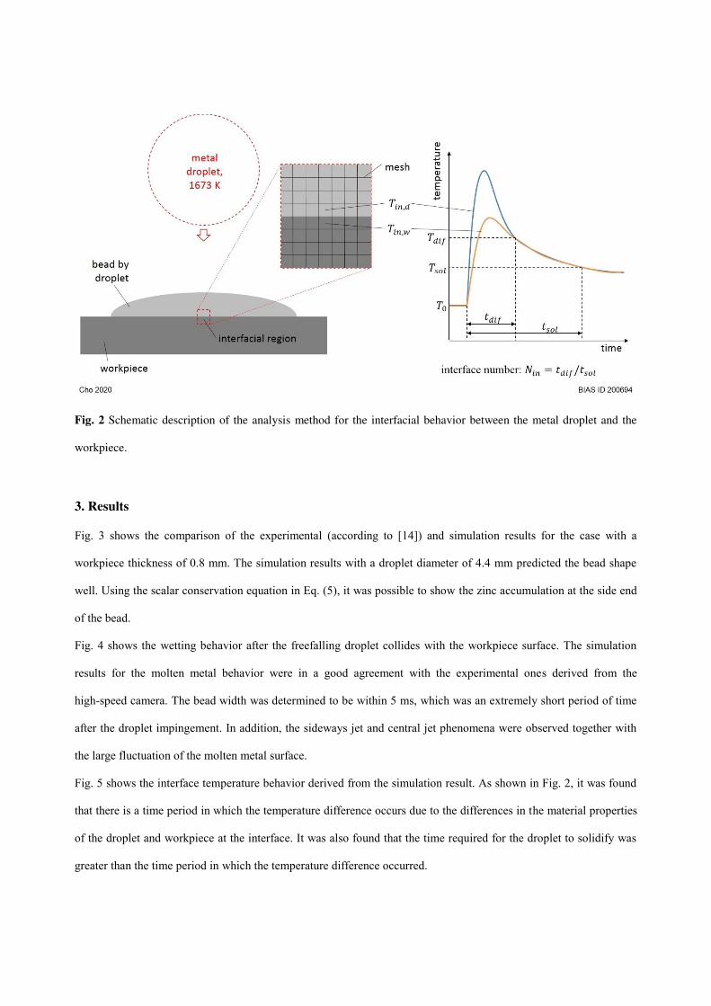
Fig. 2 Schematic description of the analysis method for the interfacial behavior between the metal droplet and the
workpiece.
3. Results
Fig. 3 shows the comparison of the experimental (according to [14]) and simulation results for the case with a
workpiece thickness of 0.8 mm. The simulation results with a droplet diameter of 4.4 mm predicted the bead shape
well. Using the scalar conservation equation in Eq. (5), it was possible to show the zinc accumulation at the side end
of the bead.
Fig. 4 shows the wetting behavior after the freefalling droplet collides with the workpiece surface. The simulation
results for the molten metal behavior were in a good agreement with the experimental ones derived from the
high-speed camera. The bead width was determined to be within 5 ms, which was an extremely short period of time
after the droplet impingement. In addition, the sideways jet and central jet phenomena were observed together with
the large fluctuation of the molten metal surface.
Fig. 5 shows the interface temperature behavior derived from the simulation result. As shown in Fig. 2, it was found
that there is a time period in which the temperature difference occurs due to the differences in the material properties
of the droplet and workpiece at the interface. It was also found that the time required for the droplet to solidify was
greater than the time period in which the temperature difference occurred.

Fig. 3 Comparison of the experimental (according to [14]) and simulation results (workpiece thickness: 0.8 mm).
Fig. 4 Molten droplet behavior on the workpiece (thickness: 0.8 mm, high speed video frames according to [14]).
Fig. 5 Analysis of the interfacial temperature using the simulation results (workpiece thickness: 0.8 mm).
Based on the model verified for a workpiece thickness of 0.8 mm, simulations were performed for various workpiece
thicknesses (0.5 mm – 1.4 mm). Fig. 6 shows the simulated bead widths for the workpiece thicknesses. Even with the
change in thickness, the bead width remained almost constant, meaning the thickness had a negligible effect on the
bead width.
Fig. 7 shows the change of 𝑡𝑠𝑜𝑙 and 𝑡𝑑𝑖𝑓 according to the workpiece thickness. 𝑡𝑠𝑜𝑙 decreased with the increase of the
thickness, whereas 𝑡𝑑𝑖𝑓 increased. In particular, the difference between them was large when the workpiece was thin,
but as the thickness increased, they converged and became similar. The characteristics of the graphs can be divided
into three sections, namely inverse (𝑡𝑠𝑜𝑙) or proportional (𝑡𝑑𝑖𝑓), singular, and convergence sections.
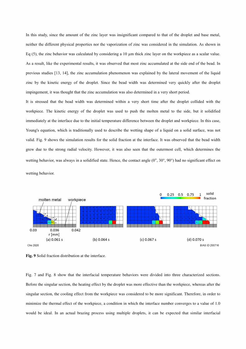
Fig. 8 presents the change of the interface number, which is the ratio of the time periods in Fig. 7, according to the
workpiece thickness. As the workpiece thickness increased, the interface number increased and converged to a value
of 1.0. Fig. 8 also shows the three characteristic sections. The number increased linearly when the thickness was thin,
and then there was a singular section (1.0 mm – 1.2 mm) in which the number increased rapidly. Finally, it
converged.
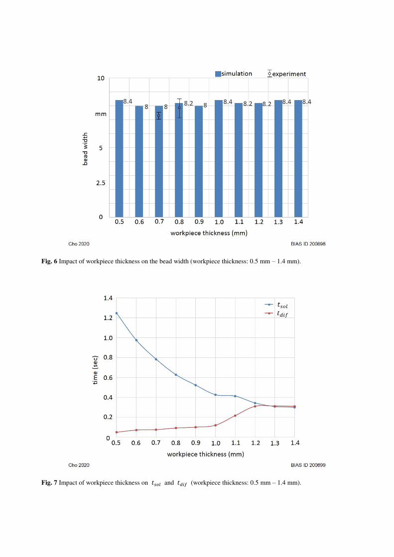
Fig. 6 Impact of workpiece thickness on the bead width (workpiece thickness: 0.5 mm – 1.4 mm).
Fig. 7 Impact of workpiece thickness on 𝑡𝑠𝑜𝑙 and 𝑡𝑑𝑖𝑓 (workpiece thickness: 0.5 mm – 1.4 mm).
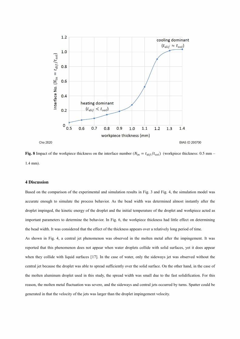
Fig. 8 Impact of the workpiece thickness on the interface number (𝑁𝑖𝑛 = 𝑡𝑑𝑖𝑓/𝑡𝑠𝑜𝑙) (workpiece thickness: 0.5 mm –
1.4 mm).
4 Discussion
Based on the comparison of the experimental and simulation results in Fig. 3 and Fig. 4, the simulation model was
accurate enough to simulate the process behavior. As the bead width was determined almost instantly after the
droplet impinged, the kinetic energy of the droplet and the initial temperature of the droplet and workpiece acted as
important parameters to determine the behavior. In Fig. 6, the workpiece thickness had little effect on determining
the bead width. It was considered that the effect of the thickness appears over a relatively long period of time.
As shown in Fig. 4, a central jet phenomenon was observed in the molten metal after the impingement. It was
reported that this phenomenon does not appear when water droplets collide with solid surfaces, yet it does appear
when they collide with liquid surfaces [17]. In the case of water, only the sideways jet was observed without the
central jet because the droplet was able to spread sufficiently over the solid surface. On the other hand, in the case of
the molten aluminum droplet used in this study, the spread width was small due to the fast solidification. For this
reason, the molten metal fluctuation was severe, and the sideways and central jets occurred by turns. Spatter could be
generated in that the velocity of the jets was larger than the droplet impingement velocity.
In this study, since the amount of the zinc layer was insignificant compared to that of the droplet and base metal,
neither the different physical properties nor the vaporization of zinc was considered in the simulation. As shown in
Eq (5), the zinc behavior was calculated by considering a 10 µm thick zinc layer on the workpiece as a scalar value.
As a result, like the experimental results, it was observed that most zinc accumulated at the side end of the bead. In
previous studies [13, 14], the zinc accumulation phenomenon was explained by the lateral movement of the liquid
zinc by the kinetic energy of the droplet. Since the bead width was determined very quickly after the droplet
impingement, it was thought that the zinc accumulation was also determined in a very short period.
It is stressed that the bead width was determined within a very short time after the droplet collided with the
workpiece. The kinetic energy of the droplet was used to push the molten metal to the side, but it solidified
immediately at the interface due to the initial temperature difference between the droplet and workpiece. In this case,
Young's equation, which is traditionally used to describe the wetting shape of a liquid on a solid surface, was not
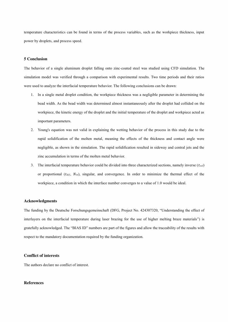
valid. Fig. 9 shows the simulation results for the solid fraction at the interface. It was observed that the bead width
grew due to the strong radial velocity. However, it was also seen that the outermost cell, which determines the
wetting behavior, was always in a solidified state. Hence, the contact angle (0°, 30°, 90°) had no significant effect on
wetting behavior.
Fig. 9 Solid fraction distribution at the interface.
Fig. 7 and Fig. 8 show that the interfacial temperature behaviors were divided into three characterized sections.
Before the singular section, the heating effect by the droplet was more effective than the workpiece, whereas after the
singular section, the cooling effect from the workpiece was considered to be more significant. Therefore, in order to
minimize the thermal effect of the workpiece, a condition in which the interface number converges to a value of 1.0
would be ideal. In an actual brazing process using multiple droplets, it can be expected that similar interfacial
temperature characteristics can be found in terms of the process variables, such as the workpiece thickness, input
power by droplets, and process speed.
5 Conclusion
The behavior of a single aluminum droplet falling onto zinc-coated steel was studied using CFD simulation. The
simulation model was verified through a comparison with experimental results. Two time periods and their ratios
were used to analyze the interfacial temperature behavior. The following conclusions can be drawn:
1. In a single metal droplet condition, the workpiece thickness was a negligible parameter in determining the
bead width. As the bead width was determined almost instantaneously after the droplet had collided on the
workpiece, the kinetic energy of the droplet and the initial temperature of the droplet and workpiece acted as
important parameters.
2. Young's equation was not valid in explaining the wetting behavior of the process in this study due to the
rapid solidification of the molten metal, meaning the effects of the thickness and contact angle were
negligible, as shown in the simulation. The rapid solidification resulted in sideway and central jets and the
zinc accumulation in terms of the molten metal behavior.
3. The interfacial temperature behavior could be divided into three characterized sections, namely inverse (𝑡𝑠𝑜𝑙) or proportional (𝑡𝑑𝑖𝑓, 𝑁𝑖𝑛), singular, and convergence. In order to minimize the thermal effect of the
workpiece, a condition in which the interface number converges to a value of 1.0 would be ideal.
Acknowledgments
The funding by the Deutsche Forschungsgemeinschaft (DFG, Project No. 424307320, “Understanding the effect of
interlayers on the interfacial temperature during laser brazing for the use of higher melting braze materials”) is
gratefully acknowledged. The “BIAS ID” numbers are part of the figures and allow the traceability of the results with
respect to the mandatory documentation required by the funding organization.
Conflict of interests
The authors declare no conflict of interest.
References
[1] Martinsen, K., Hu, S. J., Carlson, B. E., 2015. Joining of dissimilar materials. CIRP Annals, 64(2), 679–699.
[2] Meschut, G., Janzen, V.,Olfermann, T., 2014. Innovative and Highly Productive Joining Technologies for
Multi-Material Lightweight Car Body Structures. J. Mater. Eng. Perform. 23, 1515–1523.
[3] Möller, F., Thomy, C., 2013. Laser welding and brazing of dissimilar materials. In: Handbook of laser welding
technologies. Ed. Katayama, S., Woodhead Publishing Cambridge, 255 – 279.
[4] Calliari, I., Ramous, E., Brunelli, K., Dabalà, M., Favaron, P. 2004. Characterization of Vacuum Brazed Joints
for Superconducting Cavities. Microchim. Acta 147(3), 141-146.
[5] Sechi, Y., Tsumura, T., Nakata, K., 2010. Dissimilar laser brazing of boron nitride and tungsten carbide. Mater.
Des. 31(4), 2071–2077.
[6] Jia, L., Jiang, J., Shi, Y., Ni, C., Chen, J., Huang, G., 2015. Effect of zinc on the laser welding of an aluminium
alloy and galvanized steel. J. Mater. Process. Technol. 224, 49–59.
[7] Peyre, P., Sierra, G., Deschaux-Beaume, F., Stuart, D., Fras, G., 2007. Generation of aluminium-steel joints with
laser-induced reactive wetting. Mater. Sci. Eng. A 444, 327–338.
[8] Koltsov, A., Bailly, N., Cretteur, L., 2010. Wetting and laser brazing of Zn-coated steel products by Cu-Si filler
metal. J. Mater. Sci. 45, 2118–2125.
[9] Tan, C.W., Li, L.Q., Chen, Y.B., Mei, C.X., Guo, W., 2013. Interfacial microstructure and fracture behaviour of
laser welded-brazed Mg alloy to zinc coated steel. Int. J. Adv. Manuf. Technol. 68, 1179–1188.
[10] Govekar, E., Jeric, A., Weigl, M., Schmidt, M., 2009. Laser droplet generation: Application to droplet joining.
CIRP Ann. Manuf. Technol. 58, 205–208.
[11] Thomy, C., Vollertsen, F., 2012. Laser-MIG hybrid welding of aluminium to steel—Effect of process
parameters on joint properties. Weld. World 56, 124–132.
[12] Gatzen, M., Radel, T., Thomy, C., Vollertsen, F., 2014. Wetting behavior of eutectic Al-Si droplets on zinc
coated steel substrate. J. Mater. Process. Technol.214, 123–131.
[13] Agudo, L., Eyidi, D., Schmaranzer, C.H., Arenholz, E., Jank, N., Bruckner, J., Pyzalla, A.R., 2007. Intermetallic
FexAly-phases in a steel/Al-alloy fusion weld. J. Mater. Sci. 42, 4205–4214.
[14] Gatzen, M., Woizeschke, P., Radel, T., Thomy, C., Vollertsen, F., 2017. Experimental and Numerical
Investigation of an Overheated Aluminum Droplet Wetting a Zinc-Coated Steel Surface. Metals 7, 535.
[15] FLOW-3D User Manual. 2016. Version 11.2, Flow Science Inc.
[16] Keene, B., 1993. Review of data for the surface tension of pure metals. Int. Mater. Rev. 38, 157-192.
[17] Rein, M., 1993. Phenomena of liquid drop impact on solid and liquid surfaces. Fluid Dyn. Res. 12, 61-93.