Embed Size (px)
Citation preview

Nuvation Energy Stack Switchgear
NUVSSG Datasheet
Document ID: NE-DS-005 | Revision: 2.1, 2020-03-09
© 2020 Nuvation Energy

Table of Contents
1. System Overview. . . . . . . . . . . . . . . . . . . . . . . . . . . . . . . . . . . . . . . . . . . . . . . . . . . . . . . . . 1
2. Internal Hardware Overview . . . . . . . . . . . . . . . . . . . . . . . . . . . . . . . . . . . . . . . . . . . . . . . . . 4
2.1. Nuvation Energy Stack Controller and Power Interface. . . . . . . . . . . . . . . . . . . . . . . . . . . . 4
2.2. Current Measuring Shunt . . . . . . . . . . . . . . . . . . . . . . . . . . . . . . . . . . . . . . . . . . . . . . . . 4
2.3. DC Contactors. . . . . . . . . . . . . . . . . . . . . . . . . . . . . . . . . . . . . . . . . . . . . . . . . . . . . . . . 4
2.4. Pre-Charge Circuit . . . . . . . . . . . . . . . . . . . . . . . . . . . . . . . . . . . . . . . . . . . . . . . . . . . . . 4
2.5. Fuses . . . . . . . . . . . . . . . . . . . . . . . . . . . . . . . . . . . . . . . . . . . . . . . . . . . . . . . . . . . . . . 5
2.6. Safety Relay (for E-Stop) . . . . . . . . . . . . . . . . . . . . . . . . . . . . . . . . . . . . . . . . . . . . . . . . 5
3. External Interfaces . . . . . . . . . . . . . . . . . . . . . . . . . . . . . . . . . . . . . . . . . . . . . . . . . . . . . . . 6
3.1. Ethernet . . . . . . . . . . . . . . . . . . . . . . . . . . . . . . . . . . . . . . . . . . . . . . . . . . . . . . . . . . . . 6
3.2. Link Out . . . . . . . . . . . . . . . . . . . . . . . . . . . . . . . . . . . . . . . . . . . . . . . . . . . . . . . . . . . . 6
3.3. Internal Power . . . . . . . . . . . . . . . . . . . . . . . . . . . . . . . . . . . . . . . . . . . . . . . . . . . . . . . 6
3.4. Battery Stack and DC Bus . . . . . . . . . . . . . . . . . . . . . . . . . . . . . . . . . . . . . . . . . . . . . . . 7
3.5. Panel Status LEDs . . . . . . . . . . . . . . . . . . . . . . . . . . . . . . . . . . . . . . . . . . . . . . . . . . . . . 8
3.6. Manual Service Disconnect . . . . . . . . . . . . . . . . . . . . . . . . . . . . . . . . . . . . . . . . . . . . . . . 8
3.7. Fan Control . . . . . . . . . . . . . . . . . . . . . . . . . . . . . . . . . . . . . . . . . . . . . . . . . . . . . . . . . . 8
3.8. E-Stop Input . . . . . . . . . . . . . . . . . . . . . . . . . . . . . . . . . . . . . . . . . . . . . . . . . . . . . . . . 10
4. Operating Limits . . . . . . . . . . . . . . . . . . . . . . . . . . . . . . . . . . . . . . . . . . . . . . . . . . . . . . . . 11
4.1. External Specifications . . . . . . . . . . . . . . . . . . . . . . . . . . . . . . . . . . . . . . . . . . . . . . . . . 11
4.2. Electrical Characteristics . . . . . . . . . . . . . . . . . . . . . . . . . . . . . . . . . . . . . . . . . . . . . . . . 11
4.3. Sensor Specifications . . . . . . . . . . . . . . . . . . . . . . . . . . . . . . . . . . . . . . . . . . . . . . . . . . 12
4.4. Environmental Conditions . . . . . . . . . . . . . . . . . . . . . . . . . . . . . . . . . . . . . . . . . . . . . . . 12
5. Mechanical Overview . . . . . . . . . . . . . . . . . . . . . . . . . . . . . . . . . . . . . . . . . . . . . . . . . . . . . 13
5.1. Rack-Mount, 19" . . . . . . . . . . . . . . . . . . . . . . . . . . . . . . . . . . . . . . . . . . . . . . . . . . . . . 13
5.2. Shelf-Mount . . . . . . . . . . . . . . . . . . . . . . . . . . . . . . . . . . . . . . . . . . . . . . . . . . . . . . . . 14
5.3. 2-Post Rack-Mount, 19" And 23" . . . . . . . . . . . . . . . . . . . . . . . . . . . . . . . . . . . . . . . . . . 14
5.4. Dimensions . . . . . . . . . . . . . . . . . . . . . . . . . . . . . . . . . . . . . . . . . . . . . . . . . . . . . . . . . 16
6. Ordering Information . . . . . . . . . . . . . . . . . . . . . . . . . . . . . . . . . . . . . . . . . . . . . . . . . . . . . 21
6.1. Nuvation Energy Stack Switchgear Variants . . . . . . . . . . . . . . . . . . . . . . . . . . . . . . . . . . 21
6.2. Mounting Brackets . . . . . . . . . . . . . . . . . . . . . . . . . . . . . . . . . . . . . . . . . . . . . . . . . . . . 21

1. System Overview
The Nuvation Energy Stack Switchgear, shown in Figure 1, is a pre-configured assembly that
incorporates the major functions of Nuvation Energy battery management system into a rack-
mountable unit which includes stack monitoring, electrical disconnects, pre-charging, current sensing,
fuses, and a safety relay for E-Stop. It also includes supporting components like power supplies,
indicator LEDs, and external-facing connectors.
Figure 1. Nuvation Energy Stack Switchgear
There are 5 voltage/current configurations available for the base Stack Switchgear unit, listed in Table
1. Orderable part numbers are listed in Section 6.
Table 1. Nuvation Energy Stack Switchgear voltage/current variants
Maximum Voltage Rating Maximum Current Rating
1000 V DC50 A
100 A
1250 V DC
150 A
250 A
350 A
The high-level Stack Switchgear system design is shown in Figure 2. Within a battery stack, the Stack
Switchgear connects to the daisy-chained Nuvation Energy Cell Interfaces. The Cell Interface modules
convert cell voltage and temperature measurements to digital values to be relayed to the Stack
Switchgear, and enable or disable cell balancing as required. Daisy-chaining the Cell Interface
modules facilitates the design of flexible and scalable battery energy storage systems.
Nuvation Energy Stack Switchgear - NUVSSG Datasheet
Document ID: NE-DS-005 1 Rev 2.1, 2020-03-09

Figure 2. Stack Switchgear system diagram
In a multi-stack configuration, as shown in Figure 3, each Stack Switchgear unit is responsible for
monitoring the state and safety of one battery stack. All Stack Switchgear units connected to a single
common DC bus in the system may be connected to a single Nuvation Energy Grid Battery Controller,
where an Operator Interface provides a unified view and central control of the multi-stack system.
Nuvation Energy Cell Interface modules and Nuvation Energy Grid Battery Controller
modules are sold separately. Datasheets are available online at
https://www.nuvationenergy.com/technical-resources.
Nuvation Energy Stack Switchgear - NUVSSG Datasheet
Document ID: NE-DS-005 2 Rev 2.1, 2020-03-09

Figure 3. Stack Switchgear multi-stack diagram
Nuvation Energy Stack Switchgear - NUVSSG Datasheet
Document ID: NE-DS-005 3 Rev 2.1, 2020-03-09
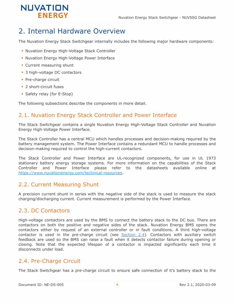
2. Internal Hardware Overview
The Nuvation Energy Stack Switchgear internally includes the following major hardware components:
▪ Nuvation Energy High-Voltage Stack Controller
▪ Nuvation Energy High-Voltage Power Interface
▪ Current measuring shunt
▪ 3 high-voltage DC contactors
▪ Pre-charge circuit
▪ 2 short-circuit fuses
▪ Safety relay (for E-Stop)
The following subsections describe the components in more detail.
2.1. Nuvation Energy Stack Controller and Power Interface
The Stack Switchgear contains a single Nuvation Energy High-Voltage Stack Controller and Nuvation
Energy High-Voltage Power Interface.
The Stack Controller has a central MCU which handles processes and decision-making required by the
battery management system. The Power Interface contains a redundant MCU to handle processes and
decision-making required to control the high-current contactors.
The Stack Controller and Power Interface are UL-recognized components, for use in UL 1973
stationary battery energy storage systems. For more information on the capabilities of the Stack
Controller and Power Interface please refer to the datasheets available online at
https://www.nuvationenergy.com/technical-resources.
2.2. Current Measuring Shunt
A precision current shunt in series with the negative side of the stack is used to measure the stack
charging/discharging current. Current measurement is performed by the Power Interface.
2.3. DC Contactors
High-voltage contactors are used by the BMS to connect the battery stack to the DC bus. There are
contactors on both the positive and negative sides of the stack. Nuvation Energy BMS opens the
contactors either by request of an external controller or in fault conditions. A third high-voltage
contactor is used in the pre-charge circuit (see Section 2.4). Contactors with auxiliary switch
feedback are used so the BMS can raise a fault when it detects contactor failure during opening or
closing. Note that the expected lifespan of a contactor is impacted significantly each time it
disconnects under load.
2.4. Pre-Charge Circuit
The Stack Switchgear has a pre-charge circuit to ensure safe connection of it’s battery stack to the
Nuvation Energy Stack Switchgear - NUVSSG Datasheet
Document ID: NE-DS-005 4 Rev 2.1, 2020-03-09
DC bus. The pre-charge circuit temporarily connects the stack to the DC bus through an appropriately
sized power resistor, which allows a smaller current (proportional to the difference in voltage between
the stack and the DC bus) to flow between the stack and the DC bus. After a 5-second pre-charge
timeout, if the measured current is below the pre-set threshold, the BMS bypasses the pre-charge
circuit by connecting the stack directly to the DC bus. This ensures the battery stack will not connect
to the DC bus when an unsafe voltage mismatch is present. By default, the Stack Switchgear is
configured with a 150 Ω, 300 W power resistor, suitable for a DC bus capacitance of 15 mF at 1000 V
and 10 mF at 1250 V. As a custom request, the pre-charge resistor can be sized specific to the end
application.
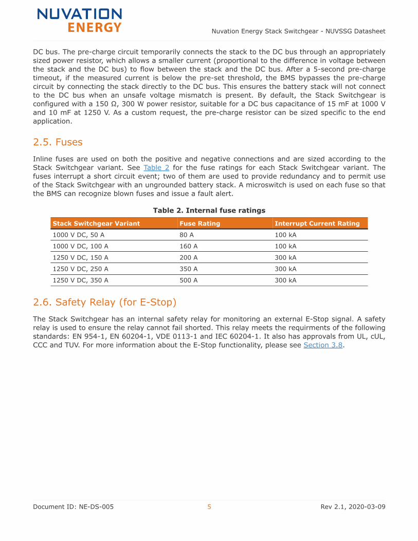
2.5. Fuses
Inline fuses are used on both the positive and negative connections and are sized according to the
Stack Switchgear variant. See Table 2 for the fuse ratings for each Stack Switchgear variant. The
fuses interrupt a short circuit event; two of them are used to provide redundancy and to permit use
of the Stack Switchgear with an ungrounded battery stack. A microswitch is used on each fuse so that
the BMS can recognize blown fuses and issue a fault alert.
Table 2. Internal fuse ratings
Stack Switchgear Variant Fuse Rating Interrupt Current Rating
1000 V DC, 50 A 80 A 100 kA
1000 V DC, 100 A 160 A 100 kA
1250 V DC, 150 A 200 A 300 kA
1250 V DC, 250 A 350 A 300 kA
1250 V DC, 350 A 500 A 300 kA
2.6. Safety Relay (for E-Stop)
The Stack Switchgear has an internal safety relay for monitoring an external E-Stop signal. A safety
relay is used to ensure the relay cannot fail shorted. This relay meets the requirments of the following
standards: EN 954-1, EN 60204-1, VDE 0113-1 and IEC 60204-1. It also has approvals from UL, cUL,
CCC and TUV. For more information about the E-Stop functionality, please see Section 3.8.
Nuvation Energy Stack Switchgear - NUVSSG Datasheet
Document ID: NE-DS-005 5 Rev 2.1, 2020-03-09
3. External Interfaces
The Nuvation Energy Stack Switchgear provides the following external interfaces:
▪ Ethernet
▪ Link Out
▪ Internal Power
▪ Battery Stack and DC Bus
▪ Panel Status LEDs
▪ Manual service disconnect
▪ Fan control
▪ E-Stop input
The following subsections describe each interface in more detail.
3.1. Ethernet
The Ethernet interface is used as the primary means of connecting an external system to the Stack
Switchgear to configure operating parameters and observe its status. It allows an external controller
to collect information from Nuvation Energy BMS on the state of the battery and to request the Stack
Switchgear to connect or disconnect the battery from the system. The connector is a standard RJ45
Cat5e rated jack; it provides a MESA Draft 3 compliant interface over Modbus-TCP/IP. For more
information, please refer to the communication protocol reference guide on the technical resources
webpage, at https://www.nuvationenergy.com/technical-resources.
3.2. Link Out
The Link Out connector is a 4-pin Micro-Fit 3.0™ Molex connector. This interface is used to connect
the Stack Switchgear to the string of one or more Cell Interface modules. The Link Out connector can
optionally provide operating power to the Cell Interface modules.
3.3. Internal Power
The default Stack Switchgear requires 100 V to 240 V AC power to be supplied from an external
source. Power is connected via feed-through connectors on the front panel, as shown in Table 3. To
install a conductor, insert a tool (such as a small flat screwdriver) into the rectangular opening at the
top of the connector. This allows the conductor to freely enter into the circular opening at the bottom
of the connector. Remove the tool to secure the conductor in place.
See Section 4.1 for specifications of this input. An inline breaker provides the ability to turn off input
power for the Stack Switchgear. It also protects the system by tripping if the input current exceeds 5
A.
For the breaker’s safety mechanism to work as expected, the input power wiring
must also be rated to at least 5 A.
Nuvation Energy Stack Switchgear - NUVSSG Datasheet
Document ID: NE-DS-005 6 Rev 2.1, 2020-03-09

Table 3. Internal power pinout
Pin Name Description Connected to Device
1 G Ground External power source
2 N Neutral External power source
3 L Line External power source
3.4. Battery Stack and DC Bus
There are 4 high power connectors, included with the unit, to be used on the front panel of the Stack
Switchgear, as illustrated by Table 4. Two of these are for the positive and negative terminals of the
battery stack; the other two are for the connection to the DC bus (or a power conversion system in a
single stack system). The plugs need to be crimped onto cables and can be secured and detached
from the receptacle on the Stack Switchgear. The colours are coordinated such that red is for the
positive connections and black is for the negative connections. Connectors are sized according to the
voltage and current rating of the Stack Switchgear variant, as outlined in Table 5.
Table 4. High power connections
Nuvation Energy Stack Switchgear - NUVSSG Datasheet
Document ID: NE-DS-005 7 Rev 2.1, 2020-03-09

Name Description Connected to Device
Battery (-) Negative terminal of battery stack Battery stack
Battery (+) Positive terminal of battery stack Battery stack
DC Bus (-) Negative terminal of DC bus External equipment
DC Bus (+) Positive terminal of DC bus External equipment
Table 5. High power conductor sizes
Stack Switchgear Variant High Power Conductor Size
1000 V DC, 50 A 30 mm2 or 2 AWG
1000 V DC, 100 A 30 mm2 or 2 AWG
1250 V DC, 150 A 50 mm2 or 1/0 AWG
1250 V DC, 250 A 70 mm2 or 2/0 AWG
1250 V DC, 350 A 95 mm2 or 3/0 AWG
3.5. Panel Status LEDs
The 3 LEDs on the front panel are controlled by the Stack Controller to indicate health and functional
status to the user. The green "Power" LED indicates the system is powered on. The blue "Activity" LED
indicates the Stack Switchgear is communicating with the Grid Battery Controller or an external
controller and is receiving a heartbeat signal. The red "Fault" LED indicates the system is in a fault
state and requires attention to become operational.
3.6. Manual Service Disconnect
A manual service disconnect is accessible on the front of the Stack Switchgear, to be used for lockout-
tagout to ensure that the battery stack does not connect to the DC bus or power conversion system
during servicing.
3.7. Fan Control
This feature gives the ability for the Stack Switchgear to control external AC or DC fans for cooling
the battery cells. The fans are enabled by the BMS when battery cell temperatures exceed
configurable thresholds. The power source for the fans must be supplied to the Stack Switchgear; it
can be either AC or DC.
Connections are made via feed-through connectors on the front panel, as shown in Table 6. To install
a conductor, insert a tool (such as a small flat screwdriver) into the rectangular opening at the top of
the connector. This allows the conductor to freely enter into the circular opening at the bottom of the
connector. Remove the tool to secure the conductor in place.
An inline breaker provides the ability to turn off fan control for the Stack Switchgear. It also protects
the system by tripping if the amperage exceeds 5 A.
For the breaker’s safety mechanism to work as expected, the fan control wiring must
also be rated to at least 5 A.
Nuvation Energy Stack Switchgear - NUVSSG Datasheet
Document ID: NE-DS-005 8 Rev 2.1, 2020-03-09

Table 6. Battery cooling fan control pinout
Pin NameDescription
Connected to DeviceAC DC
Fan Input
1 G/- Ground Negative External power source
2 N Neutral NC External power source
3 L/+ Line Positive External power source
Fan Output
1 G/- Ground Negative External fan system
2 N Neutral NC External fan system
3 L/+ Line Positive External fan system
Figure 4 provides the internal wiring implementation of the fan control parts shown above. Also see
Section 4.1 for specifications of this input.
Figure 4. Battery cooling fan control wiring diagram
Nuvation Energy Stack Switchgear - NUVSSG Datasheet
Document ID: NE-DS-005 9 Rev 2.1, 2020-03-09

3.8. E-Stop Input
This feature allows a 24 V DC E-Stop signal, supplied by a source external to the Nuvation Energy
system, to trigger a BMS fault and disconnect the stack using an internal safety relay. If this signal is
interrupted for any reason (wire cut, cable disconnected, E-Stop button pushed, etc.) the contactor
coils are de-energized by the Power Interface and the battery stack disconnects from the DC bus. In
this event, the BMS will also enter a fault state. The signal is connected via feed-through connectors
on the front panel, as shown in Table 7. To install a conductor, insert a tool (such as a small flat
screwdriver) into the rectangular opening at the top of the connector. This allows the conductor to
freely enter into the circular opening at the bottom of the connector. Remove the tool to secure the
conductor in place. See Section 4.1 for specifications of this input.
Table 7. E-Stop pinout
Pin Name Description Connected to Device
1 REF Signal return External E-Stop signal
2 +24 V DC E-Stop signal External E-Stop signal
Nuvation Energy Stack Switchgear - NUVSSG Datasheet
Document ID: NE-DS-005 10 Rev 2.1, 2020-03-09

4. Operating Limits
This section outlines the operating limits of the Stack Switchgear.
Exceeding the ratings may damage the system.
4.1. External Specifications
Symbol Parameter Condition Min Typ Max Units
Vinput Stack Switchgear Input Supply AC Voltage 60 Hz 85 - 250 V AC
Iinput Stack Switchgear Input Supply AC Current 60 Hz 0.6 1.1 1.3 A AC
Pinput Stack Switchgear Input Supply AC Power - - 33.7 60 W
finput Stack Switchgear Input Supply AC Frequency - 45 50/60 65 Hz
Vfan_AC Cooling Fan AC Voltage - - - 250 V AC
Vfan_DC Cooling Fan DC Voltage - - - 50 V DC
Ifan Cooling Fan Current - - - 5 A DC/AC
VE-Stop E-Stop Voltage Rating - 19.2 24 28.8 V DC
IE-Stop E-Stop Current Rating - - - 9.6 mA DC
4.2. Electrical Characteristics
Symbol Parameter Min Typ Max Units
Stack Switchgear Configuration: XXXX V DC, YYY A*
Vstack_ov Stack Over-Voltage Threshold (contactors open) 0 Configurable XXXX V DC
Vstack_uv Stack Under-Voltage Threshold (contactors open) 0 Configurable - V DC
Idischarge_oc Stack Discharging Over-Current (contactors open) 0 Configurable YYY A DC
Icharge_oc Stack Charging Over-Current (contactors open) 0 Configurable YYY A DC
*The voltage/current configurations available are as follows:
▪ 1000 V DC, 50 A
▪ 1000 V DC, 100 A
▪ 1250 V DC, 150 A
▪ 1250 V DC, 250 A
▪ 1250 V DC, 350 A
Nuvation Energy Stack Switchgear - NUVSSG Datasheet
Document ID: NE-DS-005 11 Rev 2.1, 2020-03-09

4.3. Sensor Specifications
Symbol Parameter Min Typ Max Units
Battery Cell Specifications
Cov Cell Over-Voltage Threshold (contactors open) - Configurable - V
Cuv Cell Under-Voltage Threshold (contactors open) - Configurable - V
Temperature Sensors Specifications
Tut Under-Temperature Threshold (contactors open) - Configurable - °C
Tot Over-Temperature Threshold (contactors open) - Configurable - °C
4.4. Environmental Conditions
Symbol Parameter Min Typ Max Units
Thermal Specifications
Ta
Operating Temperature 10 25 35 °C
Storage Temperature 10 25 35 °C
Humidity Specifications
RHOperating Relative Humidity 5 - 65 %
Storage Relative Humidity 5 - 65 %
Nuvation Energy Stack Switchgear - NUVSSG Datasheet
Document ID: NE-DS-005 12 Rev 2.1, 2020-03-09

5. Mechanical Overview
The Stack Switchgear is primarily designed to fit in a standard 19" rack with a 23"-deep cabinet.
However, other mounting possibilities are supported, as the following subsections discuss. Depending
on the desired application, brackets can be ordered with part numbers listed in Section 6.2.
The Stack Switchgear is 4U (rack-units) tall. To maintain safe operating temperatures, it is
recommended to leave 1U of space above the unit for airflow. Depending on the environment, active
airflow and ambient temperature, some cases may require additional space.
The unit weighs 23 kg (50.7 lbs). Its overall dimensions, as well as mounting-specific ones, are
shown in Section 5.4. Please refer to https://www.nuvationenergy.com/technical-resources for access
to CAD files.
5.1. Rack-Mount, 19"
As mentioned above, this is the most common use-case for mounting the Stack Switchgear, shown in
Figure 5. The mounting brackets allow for adjusting how far the unit protrudes or receeds from the
front of the rack; see Figure 9 for precise dimensions. Also, these brackets are designed to secure the
front of the unit with respect to the front of the rack. As such, the following note is important.
Third-party side-support angle brackets are necessary to uphold the weight of the
unit, in this mounting application. Some examples include Hammond Manufacturing’s
RASA22BK3 or RAAB2436BK products; details are available on their website.
Figure 5. Rack-mount, 19"
Nuvation Energy Stack Switchgear - NUVSSG Datasheet
Document ID: NE-DS-005 13 Rev 2.1, 2020-03-09

5.2. Shelf-Mount
A Stack Switchgear may also be mounted to the underlying surface on which it rests, with the aid of
shelf-mount brackets as illustrated in Figure 6
Figure 6. Shelf-mount
5.3. 2-Post Rack-Mount, 19" And 23"
Brackets are available for 2-post open-frame racks; mounting widths of 19" and 23" are both
supported. Figure 7 depicts this scenario.
Note that third-party side-support 2-post-extension brackets are available, though not necessary.
One example is Hammond Manufacturing’s RDAB2U26 product; details are available on their website.
Nuvation Energy Stack Switchgear - NUVSSG Datasheet
Document ID: NE-DS-005 14 Rev 2.1, 2020-03-09

Figure 7. Rack-mount, 2-post, 19" & 23"
Nuvation Energy Stack Switchgear - NUVSSG Datasheet
Document ID: NE-DS-005 15 Rev 2.1, 2020-03-09
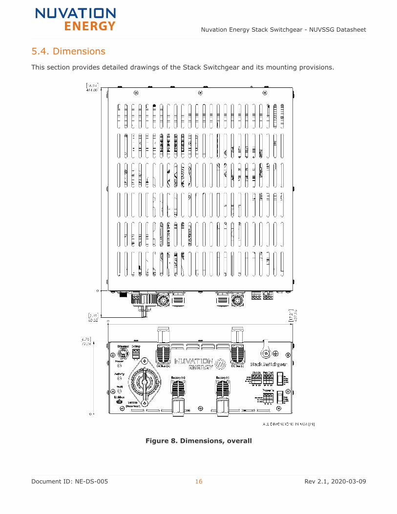
5.4. Dimensions
This section provides detailed drawings of the Stack Switchgear and its mounting provisions.
Figure 8. Dimensions, overall
Nuvation Energy Stack Switchgear - NUVSSG Datasheet
Document ID: NE-DS-005 16 Rev 2.1, 2020-03-09

Figure 9. Dimensions, rack-mount, 19"
Nuvation Energy Stack Switchgear - NUVSSG Datasheet
Document ID: NE-DS-005 17 Rev 2.1, 2020-03-09

Figure 10. Dimensions, shelf-mount
Nuvation Energy Stack Switchgear - NUVSSG Datasheet
Document ID: NE-DS-005 18 Rev 2.1, 2020-03-09

Figure 11. Dimensions, 2-post rack-mount, 19"
Nuvation Energy Stack Switchgear - NUVSSG Datasheet
Document ID: NE-DS-005 19 Rev 2.1, 2020-03-09

Figure 12. Dimensions, 2-post rack-mount, 23"
Nuvation Energy Stack Switchgear - NUVSSG Datasheet
Document ID: NE-DS-005 20 Rev 2.1, 2020-03-09

6. Ordering Information
This section provides orderable part numbers for Nuvation Energy’s offerings of Stack Switchgears
and mounting accessories.
6.1. Nuvation Energy Stack Switchgear Variants
Stack Switchgear Variant Part Number
1000 V DC, 50 A NUVSSG-1000-50
1000 V DC, 100 A NUVSSG-1000-100
1250 V DC, 150 A NUVSSG-1250-150
1250 V DC, 250 A NUVSSG-1250-250
1250 V DC, 350 A NUVSSG-1250-350
Besides the above standard configurations of the Stack Switchgear, the following options can be
offered depending on order volumes. Please contact Nuvation Energy for more information.
▪ Omission of E-Stop feature
▪ Substitution of 100-240 V AC input power voltage with 24 V DC input power voltage instead
▪ Addition of blackstart feature
Including the blackstart feature option limits the maximum voltage rating of all Stack
Switchgear variants to 1000 V DC.
6.2. Mounting Brackets
Mounting Application Part Number
Shelf NUVP-SSG-SB
19" rack, cabinet NUVP-SSG-RB-19
19" rack, 2-post NUVP-SSG-RB-19-2P
23" rack, 2-post NUVP-SSG-RB-23-2P
To attach these brackets to the unit, fasteners (M5 x 6 mm) will be included with any mounting
bracket orders. Fasteners for mounting the brackets to the end desired surface will not be provided,
due to its application-specific nature. In order to source these fasteners however, note that the
corresponding bracket slots have widths of 6.35 mm.
Nuvation Energy Stack Switchgear - NUVSSG Datasheet
Document ID: NE-DS-005 21 Rev 2.1, 2020-03-09

From time to time Nuvation Energy will make updates to Nuvation Energy BMS in response to
changes in available technologies, client requests, emerging energy storage standards, and other
industry requirements. The product specifications in this document, therefore, are subject to change
without notice.
© 2020 Nuvation Energy
Nuvation Energy Stack Switchgear - NUVSSG Datasheet
Document ID: NE-DS-005 22 Rev 2.1, 2020-03-09


![SAN]OSE CITYOF MemorandumFeeder from Switchgear M5 to Switchgear S16B 6. Feeder from Switchgear M5 to Switchgear ESB Engineer'sEstimate $384,787 $77,720 $211,326 $747,139 ... Ifthisproject](https://img.pdfslide.net/doc/110x75/5e7fcbe33356ee7623111eaf/sanose-cityof-feeder-from-switchgear-m5-to-switchgear-s16b-6-feeder-from-switchgear.jpg)