Embed Size (px)
Citation preview
Answers for industry.
Siemens PLM Software
NX CAM 9.0.2:
Trimming Tool Paths in the Tool
Path Editor Using a rectangle, polygon, or lasso to trim tool paths in the view plane.

2
About NX CAM
NXTM CAM software has helped many of the world’s leading manufacturers and job shops produce better
parts faster. You can also achieve similar benefits by making use of the unique advantages NX CAM
offers.
This is one of many hands-on demonstrations designed to introduce you to the powerful capabilities in
NX CAM 9.0.2. In order to run this demonstration, you will need access to NX CAM 9.0.2.
Visit the NX Manufacturing Forum to learn more, ask questions, and share comments about NX CAM.
3
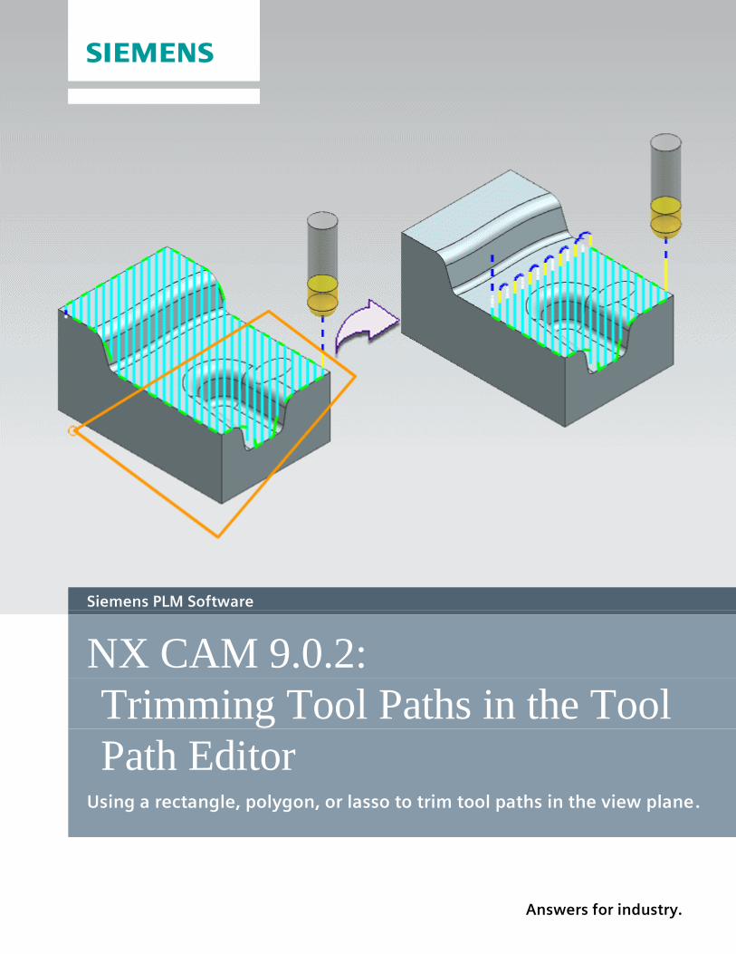
Hands-on Demonstration: Trimming Tool Paths in the Tool Path Editor
You can now use the Tool Path Editor to trim tool paths by specifying a rectangle, lasso, or polygon in
the view plane. You can also specify smooth, planar, and lowest safe z transfer moves along the
trimmed edge.
Do you have a question?
Post your questions or comments at the bottom of this Tech Tip article in the NX Manufacturing Forum.
4
Prerequisites:
1. You will need access to NX CAM 9.0.2 in order to run this demonstration.
2. If you haven’t done so already, download and unzip Trimming Tool Paths in the Tool Path
Editor.7z. You will find the .7z file attached directly to this Tech Tip article in the NX
Manufacturing Forum.
Demo:
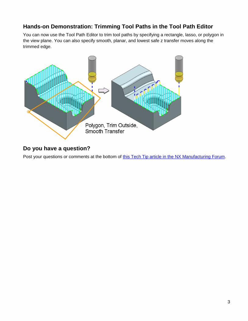
1. Open trim_in_tool_path_editor.prt in NX.
Note: It might be necessary to customize the Rectangle, Lasso, and Select by Polygon options into
the Top Border Bar. To customize, right-click in the Top Border Bar and select Customize. Select the
Commands tab. In the Categories list, expand Menu and Edit. Click Selection. In the Commands list,
find Polygon, Rectangle, and Lasso. Drag and drop them as needed into the Top Border Bar:
Trimming with a rectangle
Specifying a rectangle is the quickest and easiest way to define a simple trim area.
2. In the background of the graphics window, right-click and choose Orient ViewTop.
3. In the Operation Navigator, right-click CONTOUR_AREA and select Tool PathEdit.
4. In the Edit Actions section of the Tool Path Editor dialog box, click Trim .
5
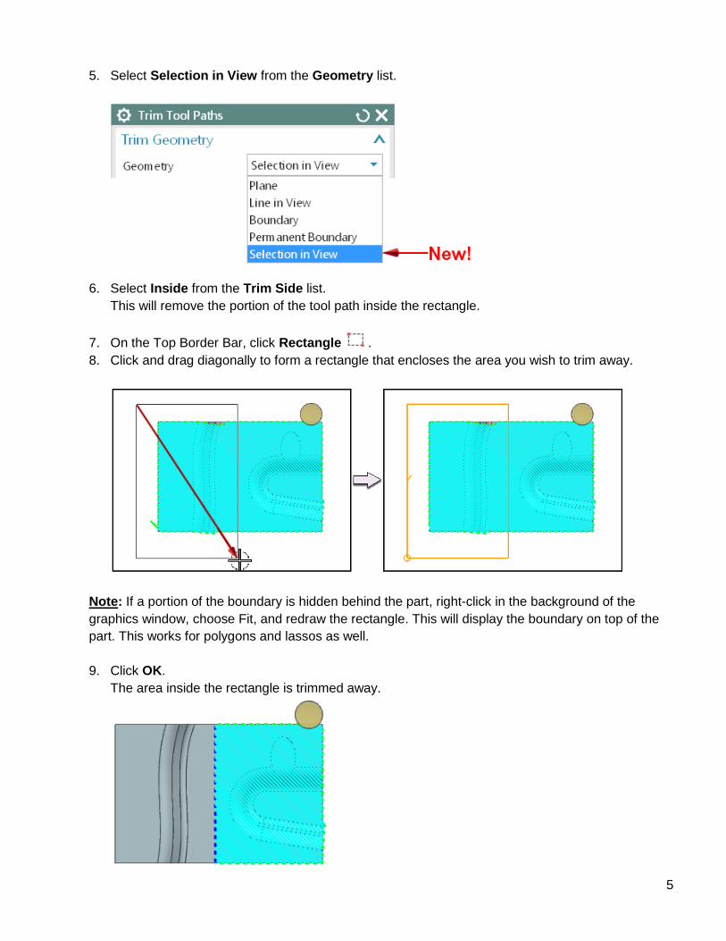
5. Select Selection in View from the Geometry list.
6. Select Inside from the Trim Side list.
This will remove the portion of the tool path inside the rectangle.
7. On the Top Border Bar, click Rectangle .
8. Click and drag diagonally to form a rectangle that encloses the area you wish to trim away.
Note: If a portion of the boundary is hidden behind the part, right-click in the background of the
graphics window, choose Fit, and redraw the rectangle. This will display the boundary on top of the
part. This works for polygons and lassos as well.
9. Click OK.
The area inside the rectangle is trimmed away.
6
10. Click OK to complete the tool path edit.
You may continue trimming.
11. Right-click CONTOUR_AREA and select Tool PathEdit.
12. Click Trim.
13. Select Selection in View from the Geometry list.
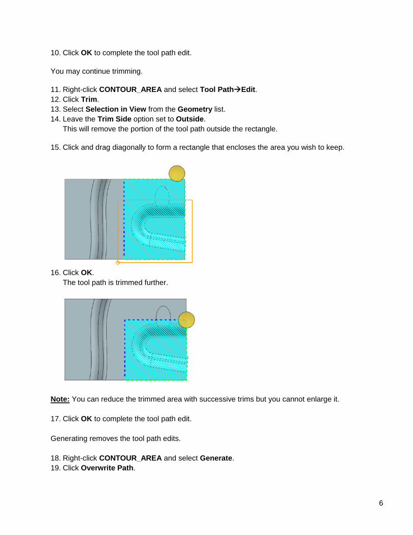
14. Leave the Trim Side option set to Outside.
This will remove the portion of the tool path outside the rectangle.
15. Click and drag diagonally to form a rectangle that encloses the area you wish to keep.
16. Click OK.
The tool path is trimmed further.
Note: You can reduce the trimmed area with successive trims but you cannot enlarge it.
17. Click OK to complete the tool path edit.
Generating removes the tool path edits.
18. Right-click CONTOUR_AREA and select Generate.
19. Click Overwrite Path.
7
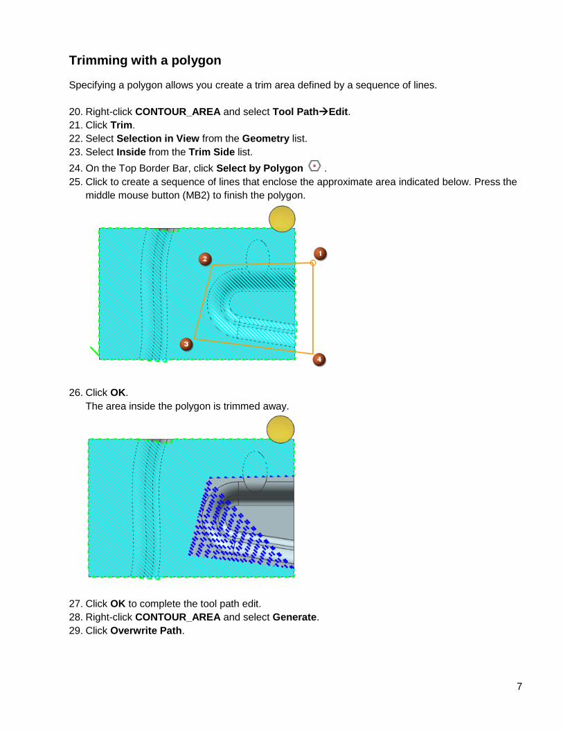
Trimming with a polygon
Specifying a polygon allows you create a trim area defined by a sequence of lines.
20. Right-click CONTOUR_AREA and select Tool PathEdit.
21. Click Trim.
22. Select Selection in View from the Geometry list.
23. Select Inside from the Trim Side list.
24. On the Top Border Bar, click Select by Polygon .
25. Click to create a sequence of lines that enclose the approximate area indicated below. Press the
middle mouse button (MB2) to finish the polygon.
26. Click OK.
The area inside the polygon is trimmed away.
27. Click OK to complete the tool path edit.
28. Right-click CONTOUR_AREA and select Generate.
29. Click Overwrite Path.
8
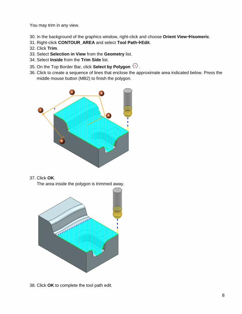
You may trim in any view.
30. In the background of the graphics window, right-click and choose Orient ViewIsomeric.
31. Right-click CONTOUR_AREA and select Tool PathEdit.
32. Click Trim.
33. Select Selection in View from the Geometry list.
34. Select Inside from the Trim Side list.
35. On the Top Border Bar, click Select by Polygon .
36. Click to create a sequence of lines that enclose the approximate area indicated below. Press the
middle mouse button (MB2) to finish the polygon.
37. Click OK.
The area inside the polygon is trimmed away.
38. Click OK to complete the tool path edit.
9
39. Right-click CONTOUR_AREA and select Generate.
40. Click Overwrite Path.
Trimming with a lasso
Lasso allows you create a trim area defined by free form shape.
41. In the background of the graphics window, right-click and choose Orient ViewTop.
42. Right-click CONTOUR_AREA and select Tool PathEdit.
43. Click Trim.
44. Select Selection in View from the Geometry list.
45. Select Inside from the Trim Side list.
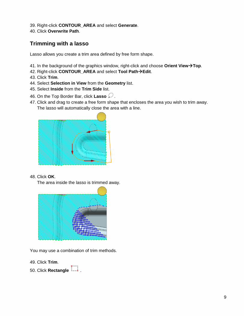
46. On the Top Border Bar, click Lasso .
47. Click and drag to create a free form shape that encloses the area you wish to trim away.
The lasso will automatically close the area with a line.
48. Click OK.
The area inside the lasso is trimmed away.
You may use a combination of trim methods.
49. Click Trim.
50. Click Rectangle .
10
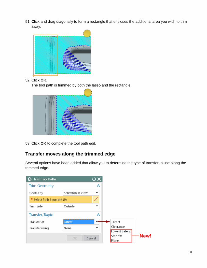
51. Click and drag diagonally to form a rectangle that encloses the additional area you wish to trim
away.
52. Click OK.
The tool path is trimmed by both the lasso and the rectangle.
53. Click OK to complete the tool path edit.
Transfer moves along the trimmed edge
Several options have been added that allow you to determine the type of transfer to use along the
trimmed edge.
11
Transfer at Smooth
The Smooth option creates the smoothest possible transition between cutting moves at the trimmed
edge.
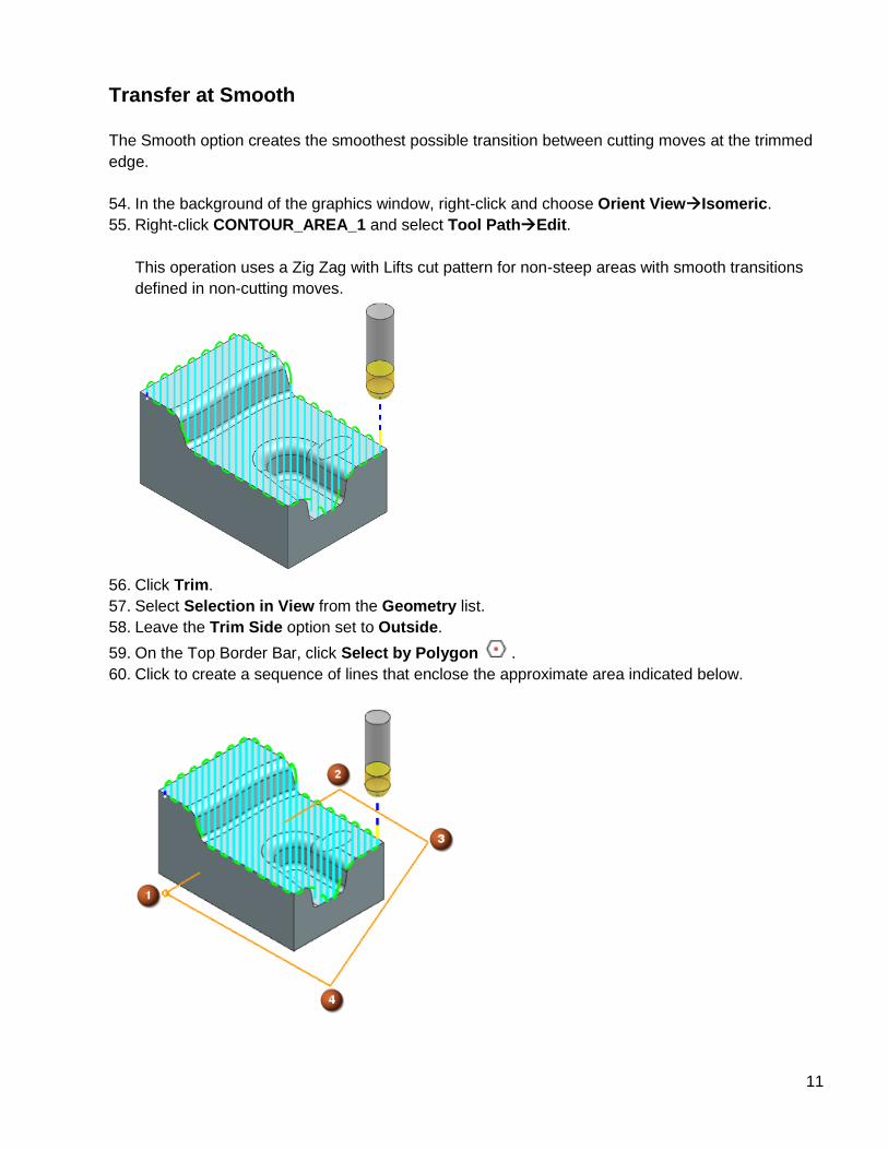
54. In the background of the graphics window, right-click and choose Orient ViewIsomeric.
55. Right-click CONTOUR_AREA_1 and select Tool PathEdit.
This operation uses a Zig Zag with Lifts cut pattern for non-steep areas with smooth transitions
defined in non-cutting moves.
56. Click Trim.
57. Select Selection in View from the Geometry list.
58. Leave the Trim Side option set to Outside.
59. On the Top Border Bar, click Select by Polygon .
60. Click to create a sequence of lines that enclose the approximate area indicated below.
12
61. Select Smooth from the Transfer at list.
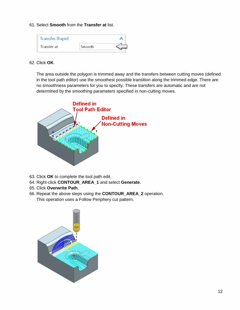
62. Click OK.
The area outside the polygon is trimmed away and the transfers between cutting moves (defined
in the tool path editor) use the smoothest possible transition along the trimmed edge. There are
no smoothness parameters for you to specify. These transfers are automatic and are not
determined by the smoothing parameters specified in non-cutting moves.
63. Click OK to complete the tool path edit.
64. Right-click CONTOUR_AREA_1 and select Generate.
65. Click Overwrite Path.
66. Repeat the above steps using the CONTOUR_AREA_2 operation.
This operation uses a Follow Periphery cut pattern.
13
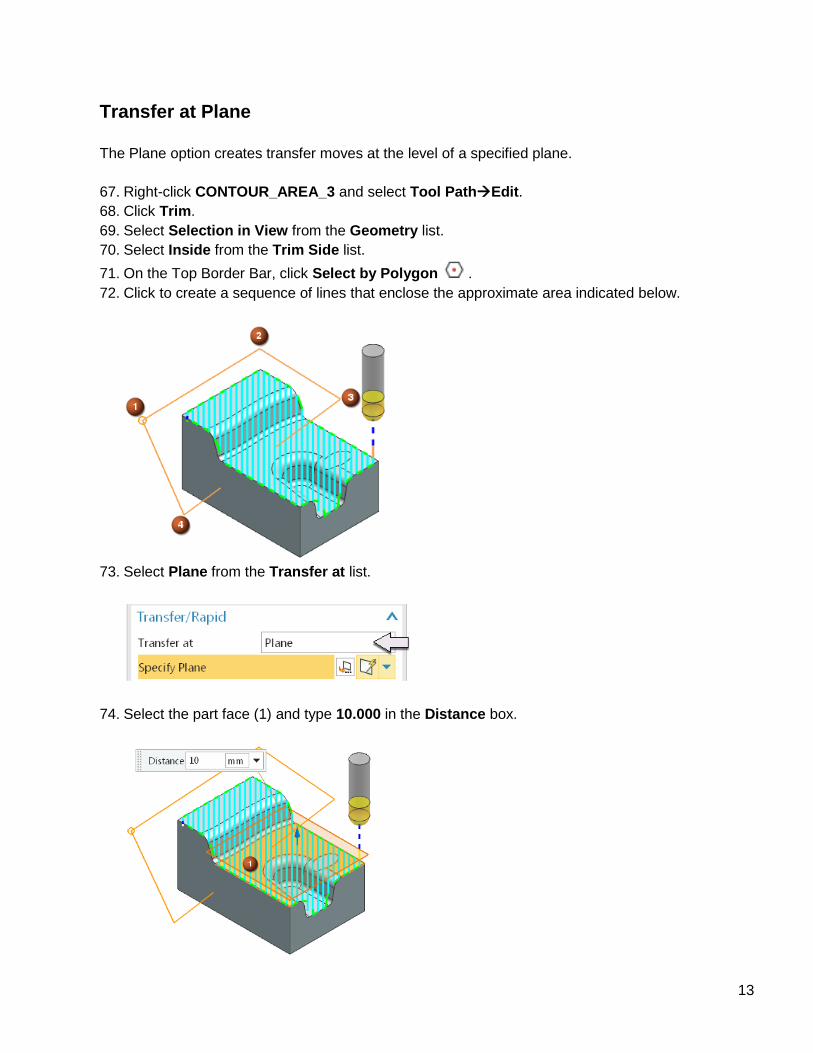
Transfer at Plane
The Plane option creates transfer moves at the level of a specified plane.
67. Right-click CONTOUR_AREA_3 and select Tool PathEdit.
68. Click Trim.
69. Select Selection in View from the Geometry list.
70. Select Inside from the Trim Side list.
71. On the Top Border Bar, click Select by Polygon .
72. Click to create a sequence of lines that enclose the approximate area indicated below.
73. Select Plane from the Transfer at list.
74. Select the part face (1) and type 10.000 in the Distance box.
14
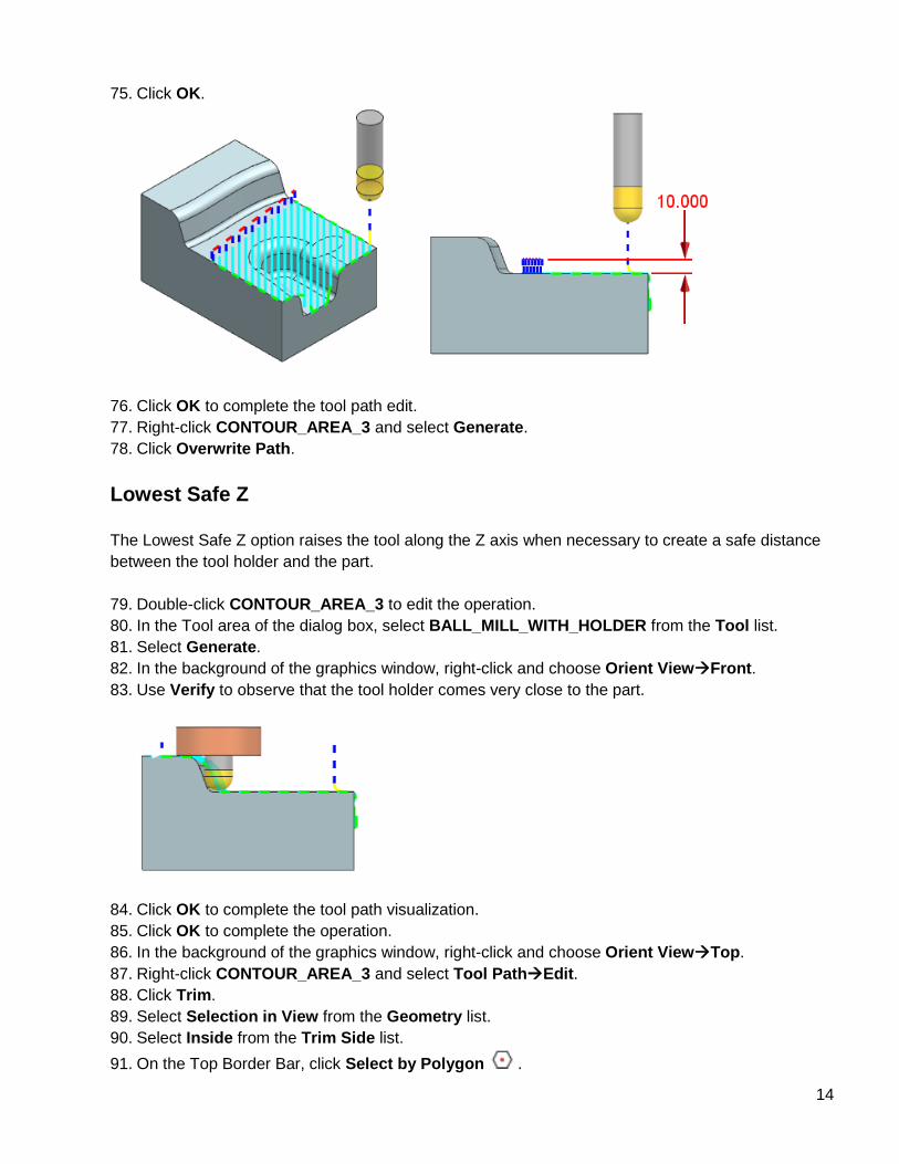
75. Click OK.
76. Click OK to complete the tool path edit.
77. Right-click CONTOUR_AREA_3 and select Generate.
78. Click Overwrite Path.
Lowest Safe Z
The Lowest Safe Z option raises the tool along the Z axis when necessary to create a safe distance
between the tool holder and the part.
79. Double-click CONTOUR_AREA_3 to edit the operation.
80. In the Tool area of the dialog box, select BALL_MILL_WITH_HOLDER from the Tool list.
81. Select Generate.
82. In the background of the graphics window, right-click and choose Orient ViewFront.
83. Use Verify to observe that the tool holder comes very close to the part.
84. Click OK to complete the tool path visualization.
85. Click OK to complete the operation.
86. In the background of the graphics window, right-click and choose Orient ViewTop.
87. Right-click CONTOUR_AREA_3 and select Tool PathEdit.
88. Click Trim.
89. Select Selection in View from the Geometry list.
90. Select Inside from the Trim Side list.
91. On the Top Border Bar, click Select by Polygon .
15
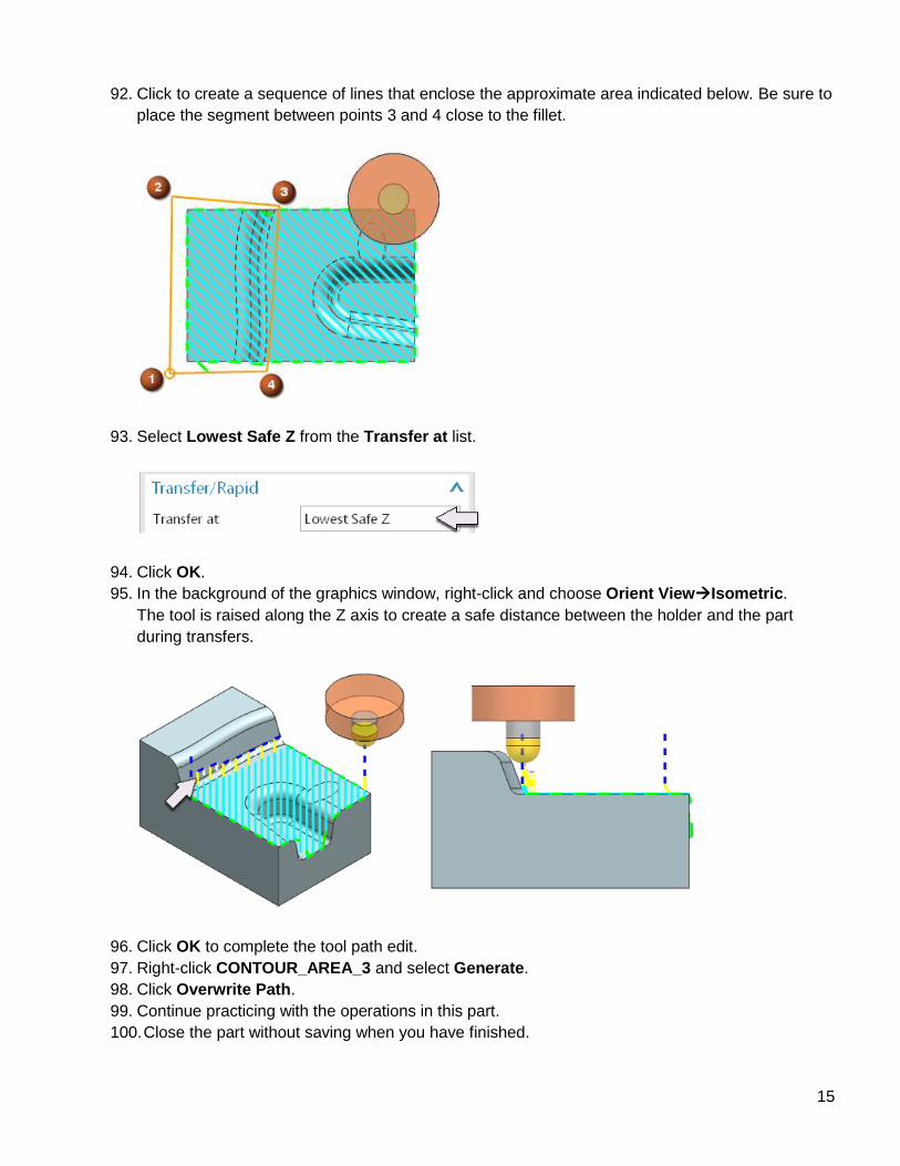
92. Click to create a sequence of lines that enclose the approximate area indicated below. Be sure to
place the segment between points 3 and 4 close to the fillet.
93. Select Lowest Safe Z from the Transfer at list.
94. Click OK.
95. In the background of the graphics window, right-click and choose Orient ViewIsometric.
The tool is raised along the Z axis to create a safe distance between the holder and the part
during transfers.
96. Click OK to complete the tool path edit.
97. Right-click CONTOUR_AREA_3 and select Generate.
98. Click Overwrite Path.
99. Continue practicing with the operations in this part.
100. Close the part without saving when you have finished.

16
About Siemens PLM Software
Siemens PLM Software, a business unit of the
Siemens Industry Automation Division, is a leading global
provider of product lifecycle management (PLM) software
and services with seven million licensed seats and more than
71,000 customers worldwide. Headquartered in Plano,
Texas, Siemens PLM Software works collaboratively with
companies to deliver open solutions that help them turn
more ideas into successful products. For more information
on Siemens PLM Software products and services, visit
www.siemens.com/plm.
© 2013 Siemens Product Lifecycle Management
Software Inc. Siemens and the Siemens logo are registered
trademarks of Siemens AG. D-Cubed, Femap, Geolus,
GO PLM, I-deas, Insight, JT, NX, Parasolid, Solid Edge,
Teamcenter, Tecnomatix and Velocity Series are trademarks
or registered trademarks of Siemens Product Lifecycle
Management Software Inc. or its subsidiaries in the United
States and in other countries. All other logos, trademarks,
registered trademarks or service marks used herein are the
property of their respective holders.
8/13
www.siemens.com/plm/nxmanufacturingforum
Siemens Industry Software
Headquarters
Granite Park One
5800 Granite Parkway
Suite 600
Plano, TX 75024
USA
+1 972 987 3000
Americas
Granite Park One
5800 Granite Parkway
Suite 600
Plano, TX 75024
USA
+1 314 264 8499
Europe
Stephenson House
Sir William Siemens Square
Frimley, Camberley
Surrey, GU16 8QD
+44 (0) 1276 413200
Asia-Pacific
Suites 4301-4302, 43/F
AIA Kowloon Tower, Landmark East
100 How Ming Street
Kwun Tong, Kowloon
Hong Kong
+852 2230 3308


![NX post processor [NX CAM]](https://img.pdfslide.net/doc/110x75/588910c81a28ab4a5c8b59e9/nx-post-processor-nx-cam.jpg)