Embed Size (px)
Citation preview
NX100 Transmitter
Installation Manual
Document:NHB-NX100-INS
Issue: 3.0 2012-11-01
Status: Standard


Nautel Limited10089 Peggy’s Cove RoadHackett’s Cove, NS Canada B3Z 3J4Phone: +1.902.823.3900 orToll Free: +1.877.6NAUTEL (6628835) (Canada & USA only)Fax: +1.902.823.3183
Nautel Inc. 201 Target Industrial Circle Bangor, Maine USA 04401 Phone: +1.207.947.8200 Fax: +1.207.947.3693
Customer Service (24 hour support) +1.877.628.8353 (Canada & USA only)+1.902.823.5100 (International)
Email: [email protected]: www.nautel.com
The comparisons and other information provided in this document have been prepared in good faith based on publicly available information. The reader is encouraged to consult the respective manufacturer's most recent published data for verification.
© Copyright 2012 NAUTEL. All rights reserved.


NX100 Installation Manual Table of contents
Page v
Contents
Release control record ix
Preparing for installation 1-1
Unpacking and positioning 2-1
Connecting transformer taps/load wiring 3-1
Connecting the station reference ground 4-1
Connecting ac power 5-1
Adjusting the spark gap 6-1
Installing audio inputs 7-1
Planning complete? 7-1Routing cables 7-1Setting Exgine audio parameters 7-4
Installing control/monitor wiring 8-1
PLanning complete? 8-1Routing cables 8-1
Commissioning tasks 9-1
Pre-commissioning tasks 9-1Commissioning 9-2Going on-air 9-4
NX100 Installation Manual Table of contents
Page vi Issue 3.0 2012-11-01
Parts and tools 10-1
Contacting Nautel 10-1Parts supplied by Nautel 10-1Parts not supplied by Nautel 10-2Parts ordering 10-2Module replacement program 10-2Tools for installation 10-3
Pre-installation / Installation assistance 11-1
Pre-installation consulting 11-1Installation and commissioning service 11-1Online documentation 11-3On-site support 11-3Training 11-3Standard warranty 11-4Extended warranties 11-7
List of terms 12-1
NX100 Installation Manual
Issue 3.0 2012-11-01 Page vii
Release control record
Issue Date Reason
3.0 2012-11-01 Release 3 of product (NARA52B)

NX100 Installation Manual
Page viii Issue 3.0 2012-11-01
NX100 Installation Manual Preparing for installation
Issue 3.0 2012-11-01 Page 1-1
Section 1: Preparing for installation
Before installing your NX100 transmitter, perform the following steps:
1. Ensure that you have performed the pre-installation tasks described in the NX100 Pre-installation Manual.
2. Make sure that you received all the components. (Check your packing list.)
3. Inspect all crates and packages for damage.
4. Report any damage immediately to your Nautel sales representative and the carrier.
5. Move the crates as close as possible to the transmitter’s planned location.
6. Unpack the crates in accordance with the instructions provided on the outside of the crates.
• For each crate, remove the panel labelled open this side. The panel is attached using Philips head screws.
• Remove any visible packing material, including braces, from the crate's interior.
7. Review any assembly notes or instructions contained inside the transmitter crates. (For sites requiring custom configurations, the instructions provided with the transmitter replace the instructions provided here.)
8. Assemble your parts and tools. For a list of required tools, see “Parts and tools” on page 10-1.
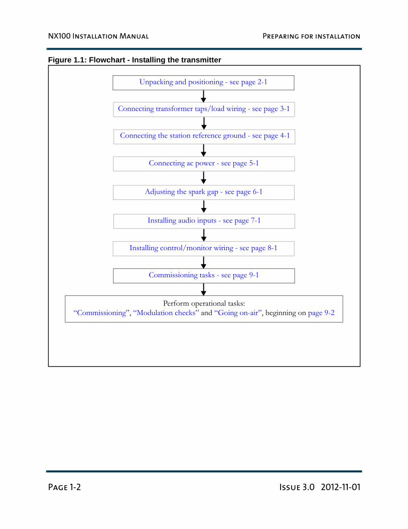
9. When you are ready to install the NX100 transmitter, follow the steps shown in Figure 1.1 on page 1-2.
TIP When you have completed a task or step, put a check mark beside the step number.
CAUTION: FAILURE TO COMPLY WITH RECOMMENDATIONS MAY VOID YOUR MANUFACTURER’S WARRANTY. FOR MORE INFORMATION, REVIEW YOUR WARRANTY DOCUMENTS.
NX100 Installation Manual Preparing for installation
Page 1-2 Issue 3.0 2012-11-01
Figure 1.1: Flowchart - Installing the transmitter
Unpacking and positioning - see page 2-1
Connecting the station reference ground - see page 4-1
Connecting transformer taps/load wiring - see page 3-1
Installing control/monitor wiring - see page 8-1
Commissioning tasks - see page 9-1
Perform operational tasks:“Commissioning”, “Modulation checks” and “Going on-air”, beginning on page 9-2
Connecting ac power - see page 5-1
Installing audio inputs - see page 7-1
Adjusting the spark gap - see page 6-1
NX100 Installation Manual Unpacking and positioning
Issue 3.0 2012-11-01 Page 2-1
Section 2: Unpacking and positioning
To install an NX100 transmitter, perform the following tasks:
1. Lift and slide the transmitter cabinets off the base of their crates. The NX100 contains two main crates - a control cabinet and a transformer cabinet. Crated and uncrated cabinet weights are shown in Table 2.1. An additional crate, which contains the ac safety interlock switch, may be provided.
Table 2.1: NX100 Cabinet Weights
2. Using necessary mechanical assistance (forklift, etc), position the twocabinets in their final location. See Figure 2.1 on page 2-2 for cabinet layout.
WARNING:
Do not move the transformer cabinet unless sufficient manpower or
mechanical assistance is available to move it into position without
damaging the cabinet or causing injury to personnel.
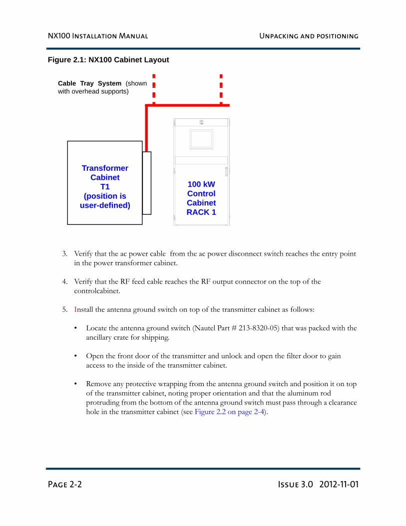
Note: The position of the transformer cabinet can be determined by the user. The cabinet’s location should accommodate input wiring from the ac power source (or ac power disconnect switch), output wiring to each of the transmitter cabinets, as well as a cable carrying system to support the output wiring..
Cabinet Crated Weightkg (lbs)
Uncrated Weightkg (lbs)
Control Cabinet 670 (1477) 567 (1250)
Transformer Cabinet 845 (1863) 753 (1659)
NX100 Installation Manual Unpacking and positioning
Page 2-2 Issue 3.0 2012-11-01
Figure 2.1: NX100 Cabinet Layout
3. Verify that the ac power cable from the ac power disconnect switch reaches the entry point in the power transformer cabinet.
4. Verify that the RF feed cable reaches the RF output connector on the top of the controlcabinet.
5. Install the antenna ground switch on top of the transmitter cabinet as follows:
• Locate the antenna ground switch (Nautel Part # 213-8320-05) that was packed with the ancillary crate for shipping.
• Open the front door of the transmitter and unlock and open the filter door to gain access to the inside of the transmitter cabinet.
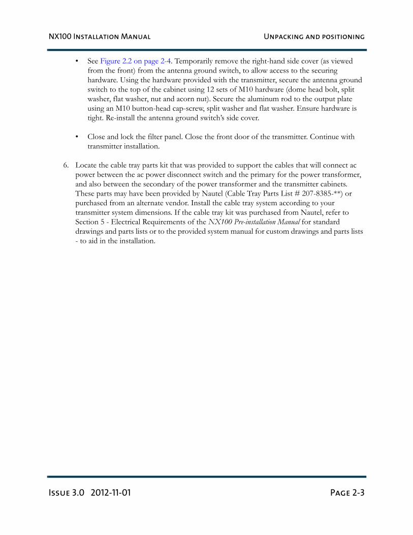
• Remove any protective wrapping from the antenna ground switch and position it on top of the transmitter cabinet, noting proper orientation and that the aluminum rod protruding from the bottom of the antenna ground switch must pass through a clearance hole in the transmitter cabinet (see Figure 2.2 on page 2-4).
100 kWControlCabinetRACK 1
TransformerCabinet
T1(position is
user-defined)
Cable Tray System (shownwith overhead supports)
NX100 Installation Manual Unpacking and positioning
Issue 3.0 2012-11-01 Page 2-3
• See Figure 2.2 on page 2-4. Temporarily remove the right-hand side cover (as viewed from the front) from the antenna ground switch, to allow access to the securing hardware. Using the hardware provided with the transmitter, secure the antenna ground switch to the top of the cabinet using 12 sets of M10 hardware (dome head bolt, split washer, flat washer, nut and acorn nut). Secure the aluminum rod to the output plate using an M10 button-head cap-screw, split washer and flat washer. Ensure hardware is tight. Re-install the antenna ground switch’s side cover.
• Close and lock the filter panel. Close the front door of the transmitter. Continue with transmitter installation.
6. Locate the cable tray parts kit that was provided to support the cables that will connect ac power between the ac power disconnect switch and the primary for the power transformer, and also between the secondary of the power transformer and the transmitter cabinets. These parts may have been provided by Nautel (Cable Tray Parts List # 207-8385-**) or purchased from an alternate vendor. Install the cable tray system according to your transmitter system dimensions. If the cable tray kit was purchased from Nautel, refer to Section 5 - Electrical Requirements of the NX100 Pre-installation Manual for standard drawings and parts lists or to the provided system manual for custom drawings and parts lists - to aid in the installation.
NX100 Installation Manual Unpacking and positioning
Page 2-4 Issue 3.0 2012-11-01
Figure 2.2: Installing Antenna Ground Switch
Antenna Ground Switch
Aluminum Rod(secure to probe bracket with
Four sets of M4 hardware(packed with antennaground switch)
antenna ground switch) M8 hardware, packed with
(Nautel Part # 207-8320)
NX100 Installation Manual Connecting transformer taps/load wiring
Issue 3.0 2012-11-01 Page 3-1
Section 3: Connecting transformer taps/
load wiring
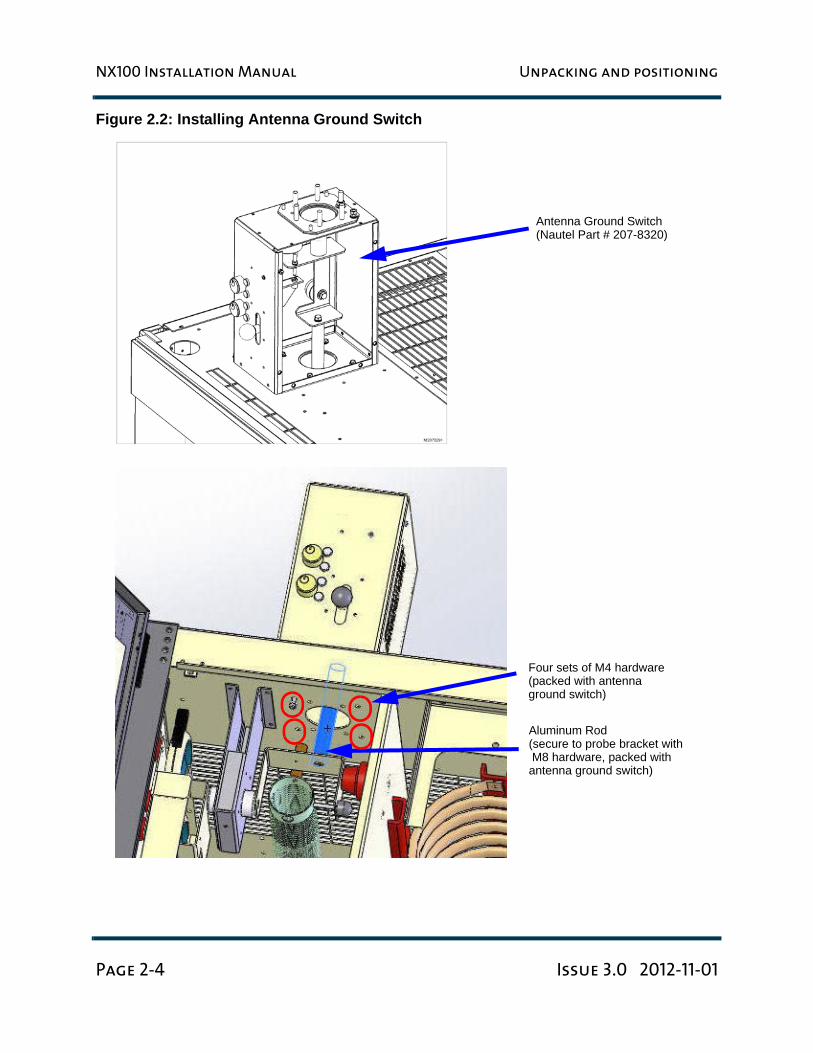
1. Before connecting ac wiring to the transformer, set the line voltage tap selections. Based on your line to line voltage under full load, select the appropriate tap position identified on the labels mounted on the terminal board end of the transformer. One label identifies the tap number and the line-to-line voltage. Another label identifies the tap. All phases must be set to the same tap (see Figure 3.1 and Table 3.1 on page 3-2). If necessary, use the hardware already on each of the three copper straps to connect the straps to the new tap positions. Be sure to scrape any excess epoxy off the electrical joint area.
Figure 3.1: NX100 power transformer line voltage tap layout
Note: It is important to choose the correct tap based on the loaded line-to-line voltage (i.e., the line voltage present when the NX100 is operating at full power and full modulation) for maximum peak modulation capability and maximum efficiency. If the loaded line-to-line voltage falls between two tap settings, choose the higher voltage tap (this will maximize the NX100‘s power factor).
2
3
4
5
6
X 3
H 3
X 2
H 2
X 1
H 1
1
X 0
NX100 Installation Manual Connecting transformer taps/load wiring
Page 3-2 Issue 3.0 2012-11-01
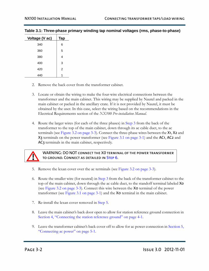
Table 3.1: Three-phase primary winding tap nominal voltages (rms, phase-to-phase)
2. Remove the back cover from the transformer cabinet.
3. Locate or obtain the wiring to make the four-wire electrical connections between the transformer and the main cabinet. This wiring may be supplied by Nautel and packed in the main cabinet or packed in the ancillary crate. If it is not provided by Nautel, it must be obtained by the user. In this case, select the wiring based on the recommendations in the Electrical Requirements section of the NX100 Pre-installation Manual.
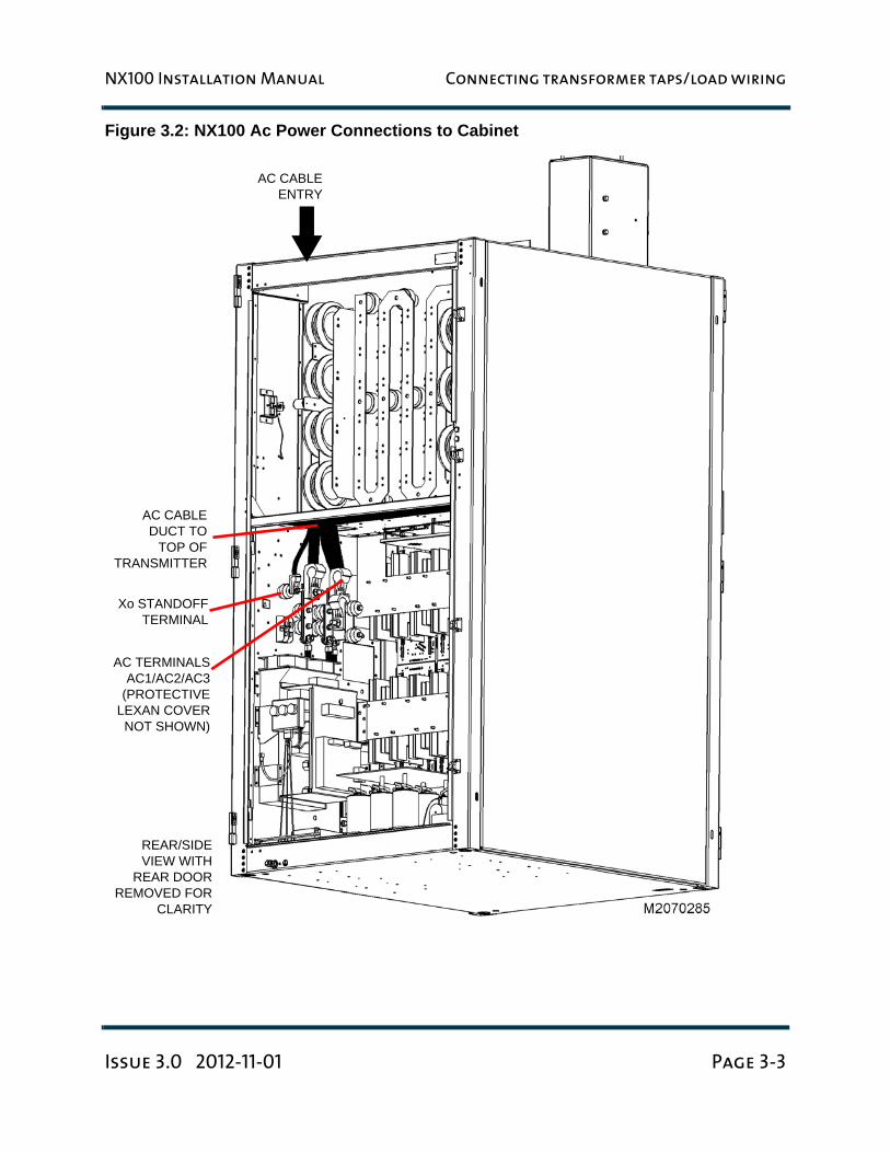
4. Route the larger wires (for each of the three phases) in Step 3 from the back of the transformer to the top of the main cabinet, down through its ac cable duct, to the ac terminals (see Figure 3.2 on page 3-3). Connect the three-phase wires between the X1, X2 and X3 terminals on the power transformer (see Figure 3.1 on page 3-1) and the AC1, AC2 and AC3 terminals in the main cabinet, respectively.
5. Remove the lexan cover over the ac terminals (see Figure 3.2 on page 3-3).
6. Route the smaller wire (for neutral) in Step 3 from the back of the transformer cabinet to the top of the main cabinet, down through the ac cable duct, to the standoff terminal labeled Xo (see Figure 3.2 on page 3-3). Connect this wire between the X0 terminal of the power transformer (see Figure 3.1 on page 3-1) and the X0 terminal in the main cabinet.
7. Re-install the lexan cover removed in Step 5.
8. Leave the main cabinet’s back door open to allow for station reference ground connection in Section 4, “Connecting the station reference ground” on page 4-1.
9. Leave the transformer cabinet’s back cover off to allow for ac power connection in Section 5, “Connecting ac power” on page 5-1.
WARNING: DO NOT connect the X0 terminal of the power transformer
to ground. Connect as detailed in Step 6.
Voltage (V ac) Tap340 6
360 5
380 4
400 3
420 2
440 1
NX100 Installation Manual Connecting transformer taps/load wiring
Issue 3.0 2012-11-01 Page 3-3
Figure 3.2: NX100 Ac Power Connections to Cabinet
Xo STANDOFFTERMINAL
AC CABLEDUCT TO
TOP OFTRANSMITTER
AC TERMINALSAC1/AC2/AC3
(PROTECTIVELEXAN COVERNOT SHOWN)
REAR/SIDEVIEW WITH
REAR DOORREMOVED FOR
CLARITY
AC CABLEENTRY
NX100 Installation Manual Connecting transformer taps/load wiring
Page 3-4 Issue 3.0 2012-11-01
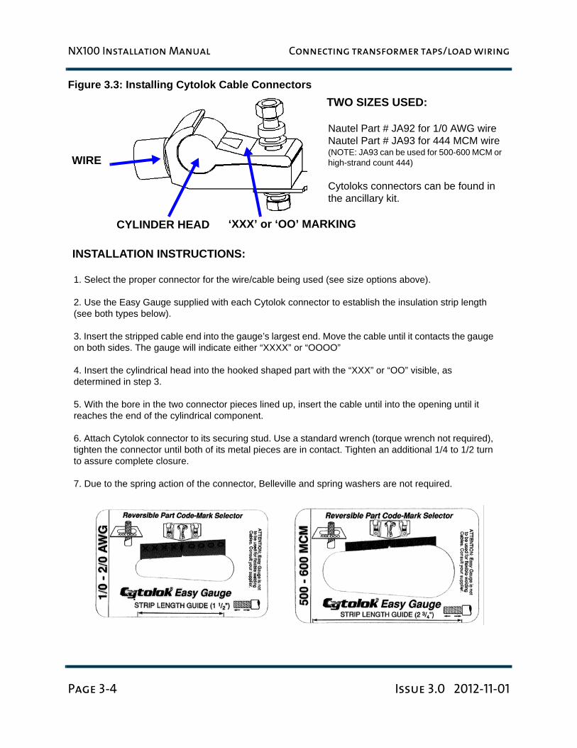
Figure 3.3: Installing Cytolok Cable Connectors
WIRE
TWO SIZES USED:
Nautel Part # JA92 for 1/0 AWG wireNautel Part # JA93 for 444 MCM wire(NOTE: JA93 can be used for 500-600 MCM or high-strand count 444)
Cytoloks connectors can be found in the ancillary kit.
INSTALLATION INSTRUCTIONS:
1. Select the proper connector for the wire/cable being used (see size options above).
2. Use the Easy Gauge supplied with each Cytolok connector to establish the insulation strip length (see both types below).
3. Insert the stripped cable end into the gauge’s largest end. Move the cable until it contacts the gauge on both sides. The gauge will indicate either “XXXX” or “OOOO”
4. Insert the cylindrical head into the hooked shaped part with the “XXX” or “OO” visible, as determined in step 3.
5. With the bore in the two connector pieces lined up, insert the cable until into the opening until it reaches the end of the cylindrical component.
6. Attach Cytolok connector to its securing stud. Use a standard wrench (torque wrench not required), tighten the connector until both of its metal pieces are in contact. Tighten an additional 1/4 to 1/2 turn to assure complete closure.
7. Due to the spring action of the connector, Belleville and spring washers are not required.
CYLINDER HEAD ‘XXX’ or ‘OO’ MARKING
NX100 Installation Manual Connecting the station reference ground
Issue 3.0 2012-11-01 Page 4-1
Section 4: Connecting the station
reference ground
To connect the station reference ground, perform the following steps:
1. Locate the safety ground stud assembly for the output cabinet. It has been set back in its final location at the bottom left rear of the cabinet.
2. Remove the two nuts holding it to the phenolic bar.
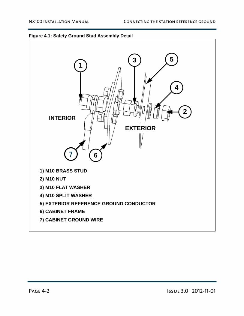
3. Re-assemble as shown in Figure 4.1. Attach a continuous, low impedance conductor (minimum four-inch copper strap, or equivalent wire) between the station reference ground and the stud assembly (E1) in the output cabinet. Ensure the reference ground conductor is at least 3 mm (1/8 in) from the cabinet’s exterior.
4. Attach a continuous, low impedance conductor (minimum four-inch copper strap, or equivalent wire) between the stud assembly (E1) in the output cabinet and the transformer cabinet’s ground stud. Ensure the reference ground conductor is at least 3 mm (or 1/8 in) from any cabinet’s exterior.
5. Firmly tighten all hardware.
Note: Proper grounding configuration is critical for protecting transmitter circuitry from lightning strikes. See the Electrical Requirements section of the NX100 Pre-Installation Manual or the Recommendations for Transmitter Site Preparation Manual for information on proper grounding and lightning protection recommendation. Failure to follow these guidelines may void your warranty.
NX100 Installation Manual Connecting the station reference ground
Page 4-2 Issue 3.0 2012-11-01
Figure 4.1: Safety Ground Stud Assembly Detail
INTERIOR
1) M10 BRASS STUD2) M10 NUT
3) M10 FLAT WASHER4) M10 SPLIT WASHER5) EXTERIOR REFERENCE GROUND CONDUCTOR6) CABINET FRAME
1
2
3 5
6
4
7
7) CABINET GROUND WIRE
EXTERIOR
NX100 Installation Manual Connecting ac power
Issue 3.0 2012-11-01 Page 5-1
Section 5: Connecting ac power
Connect ac power to the ac power disconnect switch and then to the transmitter, as follows:
1. Run the ac power cable from the ac power source to the ac power disconnect switch. The preferred entry point is through the top of the ac power disconnect switch. Cabinet punches or hole saws will be required to cut the entry holes for the conduits.
2. Open the ac power disconnect switch’s front door. Connect the ac line input from the power source to the top L1 (Line 1), L2 (Line 2) and L3 (Line 3) input terminals. Connect the ac ground to the top ground terminal.
3. Connect the ac power disconnect switch’s load wiring to the bottom T1 (Line 1), T2 (Line 2) and T3 (Line 3) terminals. Connect the ac ground to the bottom ground terminal.
4. If applicable, connect EMERGENCY STOP switch wiring between the + and - terminals of TB2, near the bottom of the ac power disconnect switch. This circuit must present a closed contact between these terminals to allow ac power to be applied to the transmitter. In some cases, Nautel may provide an EMERGENCY STOP switch. Close the ac power disconnect switch’s front door.
5. Route the load wiring from the ac power disconnect switch to the transformer cabinet, passing all the conductors, as a group, through a ferrite toroid (Nautel Part # LX63, provided in the ancillary kit)..
6. Connect the ac power ground to the station reference ground.
7. Verify that the station reference ground and the transformer ground stud are connected to the safety ground stud assembly at the back of the control cabinet.
DANGER: Ensure ac power is disconnected and locked out at the
source before proceeding.
WARNING: Ensure that wiring sizes are appropriate. ac wiring must be
installed by a qualified, locally-certified electrician.
Note: The preferred entry point for ac input wiring is through a hole in the primary side of the transformer cabinet. There is a cable tray wiring interface cover on the primary side to connect to your cable tray system, as applicable. Temporarily remove the cover to pass the primary wiring into the transformer cabinet.

NX100 Installation Manual Connecting ac power
Page 5-2 Issue 3.0 2012-11-01
8. Connect the ac line input to the H1 (Line 1), H2 (Line 2) and H3 (Line 3) input terminals on the transformer (see Figure 4.1 on page 4-1). Connect the ac ground to the transformer’s ground stud.
9. Optionally (if purchased), install the ac transient surge protection system.
NX100 Installation Manual Adjusting the spark gap
Issue 3.0 2012-11-01 Page 6-1
Section 6: Adjusting the spark gap
The NX100’s RF output filter contains a spark gap that must be adjusted - based on site altitude - to provide protection against excessive voltage (i.e., lightning) on the RF output.
If the altitude of the transmitter site is known prior to transmitter delivery, then the spark gap is adjusted at Nautel. If this is the case, it may only be necessary to verify the spark gap setting.
1. Determine the altitude of the transmitter site (in feet).
2. Make sure that the ac power is switched off and locked out. Refer to the Operating section of the NX100 Operations and Maintenance Manual for instructions on using the ac disconnect or safety interlock switch, which is provided by Nautel.
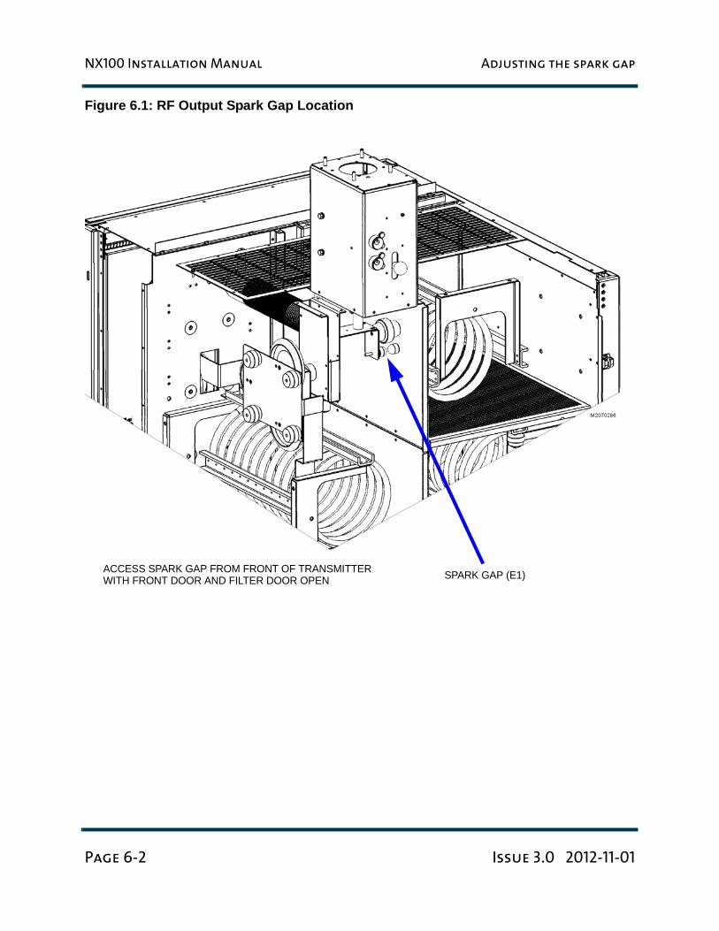
3. Gain access to the RF output spark gap, noting it is in the top section of the cabinet.
4. Locate the spark gap(see Figure 6.1 on page 6-2). Using a feeler gauge, measure the air gap between the spark gap balls.
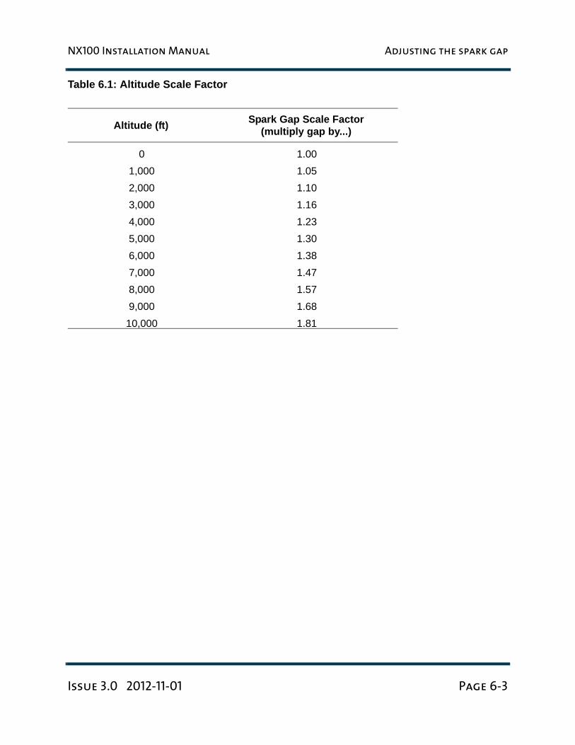
5. The air gap should be 0.179 inches multiplied by the scale factor listed in Table 6.1, “Altitude Scale Factor” on page 6-3 for the altitude determined in Step 1. If not, loosen the locking nut on the bottom carbon hemisphere, adjust the position of the spark gap ball for the required gap and then tighten the locking nut.
6. Close and secure the filter door using M5 screws.
WARNING:
THE AC VOLTAGES PRESENT IN THE TRANSMITTER CAN BE FATAL. EXERCISE
EXTREME CAUTION.
NX100 Installation Manual Adjusting the spark gap
Page 6-2 Issue 3.0 2012-11-01
Figure 6.1: RF Output Spark Gap Location
SPARK GAP (E1)ACCESS SPARK GAP FROM FRONT OF TRANSMITTERWITH FRONT DOOR AND FILTER DOOR OPEN
NX100 Installation Manual Adjusting the spark gap
Issue 3.0 2012-11-01 Page 6-3
Table 6.1: Altitude Scale Factor
Altitude (ft) Spark Gap Scale Factor(multiply gap by...)
0 1.001,000 1.052,000 1.103,000 1.164,000 1.235,000 1.306,000 1.387,000 1.478,000 1.579,000 1.68
10,000 1.81

NX100 Installation Manual Adjusting the spark gap
Page 6-4 Issue 3.0 2012-11-01
NX100 Installation Manual Installing audio inputs
Issue 3.0 2012-11-01 Page 7-1
Section 7: Installing audio inputs
This section describes how to route audio input wiring to the NX100’s exciters.
Planning complete?
1. Make sure you have read and fully understood the audio input options described in the NX100 Pre-installation Manual before proceeding.
2. Make sure the audio input wires are long enough to allow routing through the top of the transmitter cabinet and down to the exciter panel.
Routing cables
1. Route all audio cables from their audio sources to the top of the transmitter.
2. Get two ferrite toroids (one each of Nautel Part # LXP44 and LP23) from the ancillary kit.
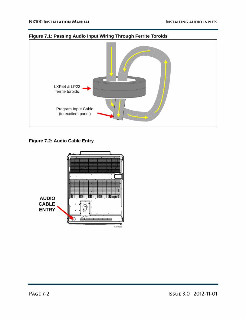
3. Pass all audio input cables through the ferrite toroids obtained in Step 2. If practical, wires should pass through a minimum of two times (two turns) (see Figure 7.1 on page 7-2). An entrance is provided at the top of the transmitter to accept audio input wiring (see Figure 7.2 on page 7-2). Position the ferrite toroids just outside, or just inside, the audio input entry hole.
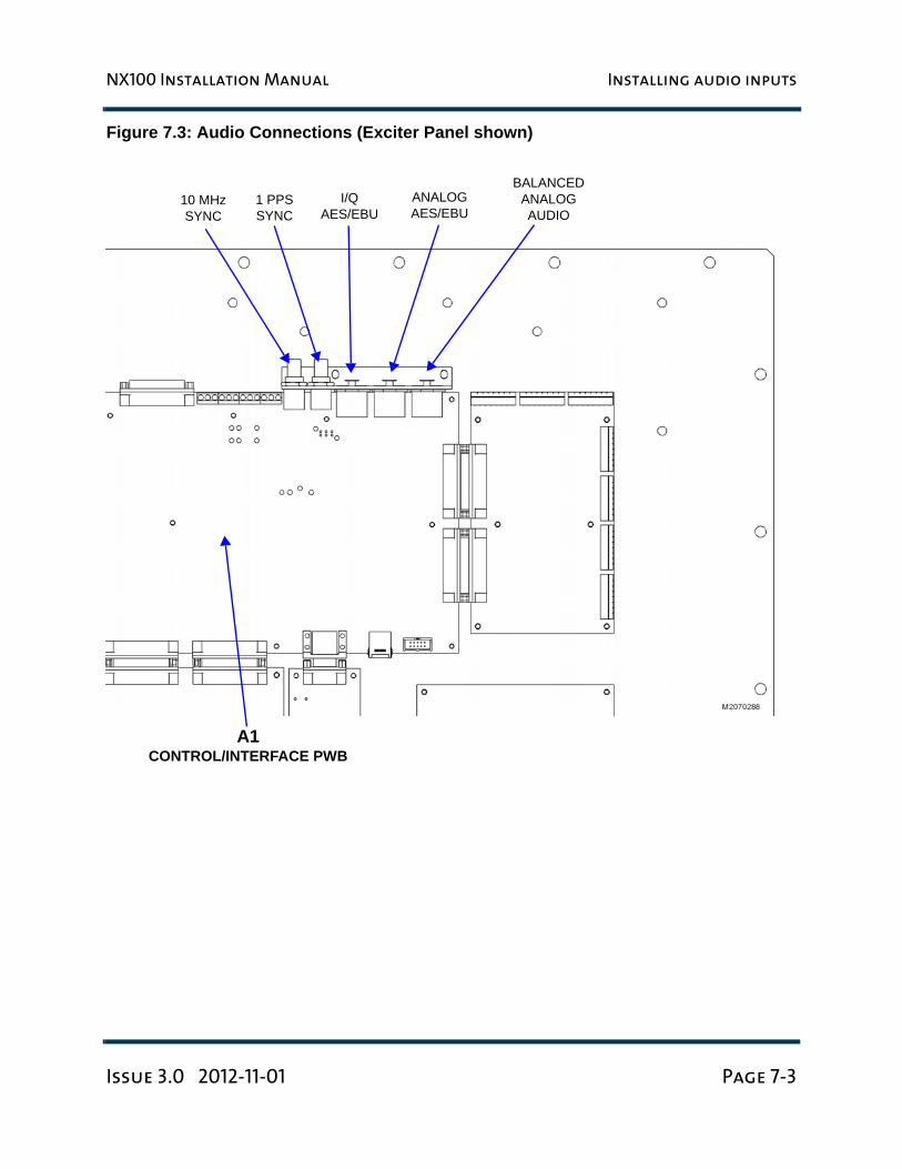
4. Route the audio input cables through the entry hole and toward the exciter panel (A11), located behind the front door (see Figure 7.3 on page 7-3). If possible, install exciter mating connectors after passing cables through the audio input entry hole.
5. With the audio input cables near their destination, cut each wire to the required length and install connectors, as necessary.
6. Remove plastic cap-plugs from the connectors on the exciter panel, if applicable.
7. Connect the appropriate audio input cable(s) to the connector(s) described in Section 7 of the NX100 Pre-installation Manual.
NX100 Installation Manual Installing audio inputs
Page 7-2 Issue 3.0 2012-11-01
Figure 7.1: Passing Audio Input Wiring Through Ferrite Toroids
Figure 7.2: Audio Cable Entry
Program Input Cable(to exciters panel)
LXP44 & LP23 ferrite toroids
AUDIOCABLEENTRY
NX100 Installation Manual Installing audio inputs
Issue 3.0 2012-11-01 Page 7-3
Figure 7.3: Audio Connections (Exciter Panel shown)
A1CONTROL/INTERFACE PWB
10 MHzSYNC
1 PPSSYNC
I/QAES/EBU
ANALOGAES/EBU
BALANCEDANALOGAUDIO
NX100 Installation Manual Installing audio inputs
Page 7-4 Issue 3.0 2012-11-01
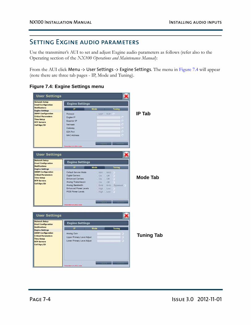
Setting Exgine audio parameters
Use the transmitter’s AUI to set and adjust Exgine audio parameters as follows (refer also to the Operating section of the NX100 Operations and Maintenance Manual):
From the AUI click Menu -> User Settings -> Exgine Settings. The menu in Figure 7.4 will appear (note there are three tab pages - IP, Mode and Tuning).
Figure 7.4: Exgine Settings menu
IP Tab
Mode Tab
Tuning Tab
NX100 Installation Manual Installing audio inputs
Issue 3.0 2012-11-01 Page 7-5
– In the IP tab, enter Exgine IP settings (see the associated Exporter manual for assistance with IP settings).
– In the Mode tab, set Digital Carriers to On or Off.– In the Mode tab, set Analog Transmission to On or Off.– In the Mode tab, set the Default Service Mode (MA1 for hybrid; MA3 for all-digital).– In the Tuning tab, adjust carrier levels by changing the values of the Upper Primary Level
Adjust and Lower Primary Level Adjust fields.– In the Tuning tab, adjust the analog gain by changing the value of the Analog Gain field.

NX100 Installation Manual Installing audio inputs
Page 7-6 Issue 3.0 2012-11-01
NX100 Installation Manual Installing control/monitor wiring
Issue 3.0 2012-11-01 Page 8-1
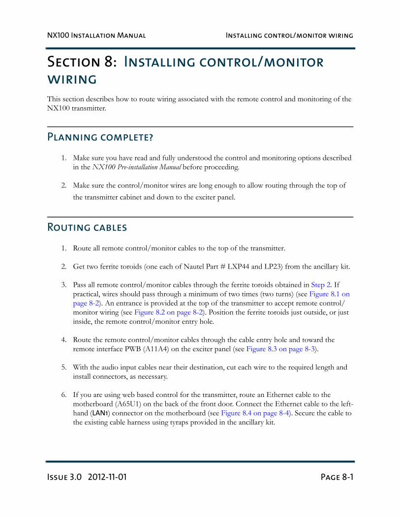
Section 8: Installing control/monitor
wiring
This section describes how to route wiring associated with the remote control and monitoring of the NX100 transmitter.
Planning complete?
1. Make sure you have read and fully understood the control and monitoring options described in the NX100 Pre-installation Manual before proceeding.
2. Make sure the control/monitor wires are long enough to allow routing through the top of the transmitter cabinet and down to the exciter panel.
Routing cables
1. Route all remote control/monitor cables to the top of the transmitter.
2. Get two ferrite toroids (one each of Nautel Part # LXP44 and LP23) from the ancillary kit.
3. Pass all remote control/monitor cables through the ferrite toroids obtained in Step 2. If practical, wires should pass through a minimum of two times (two turns) (see Figure 8.1 on page 8-2). An entrance is provided at the top of the transmitter to accept remote control/monitor wiring (see Figure 8.2 on page 8-2). Position the ferrite toroids just outside, or just inside, the remote control/monitor entry hole.
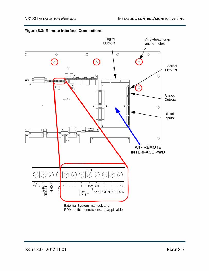
4. Route the remote control/monitor cables through the cable entry hole and toward the remote interface PWB (A11A4) on the exciter panel (see Figure 8.3 on page 8-3).
5. With the audio input cables near their destination, cut each wire to the required length and install connectors, as necessary.
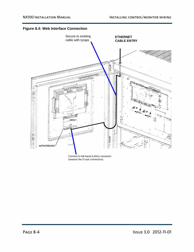
6. If you are using web based control for the transmitter, route an Ethernet cable to the motherboard (A65U1) on the back of the front door. Connect the Ethernet cable to the left-hand (LAN1) connector on the motherboard (see Figure 8.4 on page 8-4). Secure the cable to the existing cable harness using tyraps provided in the ancillary kit.
NX100 Installation Manual Installing control/monitor wiring
Page 8-2 Issue 3.0 2012-11-01
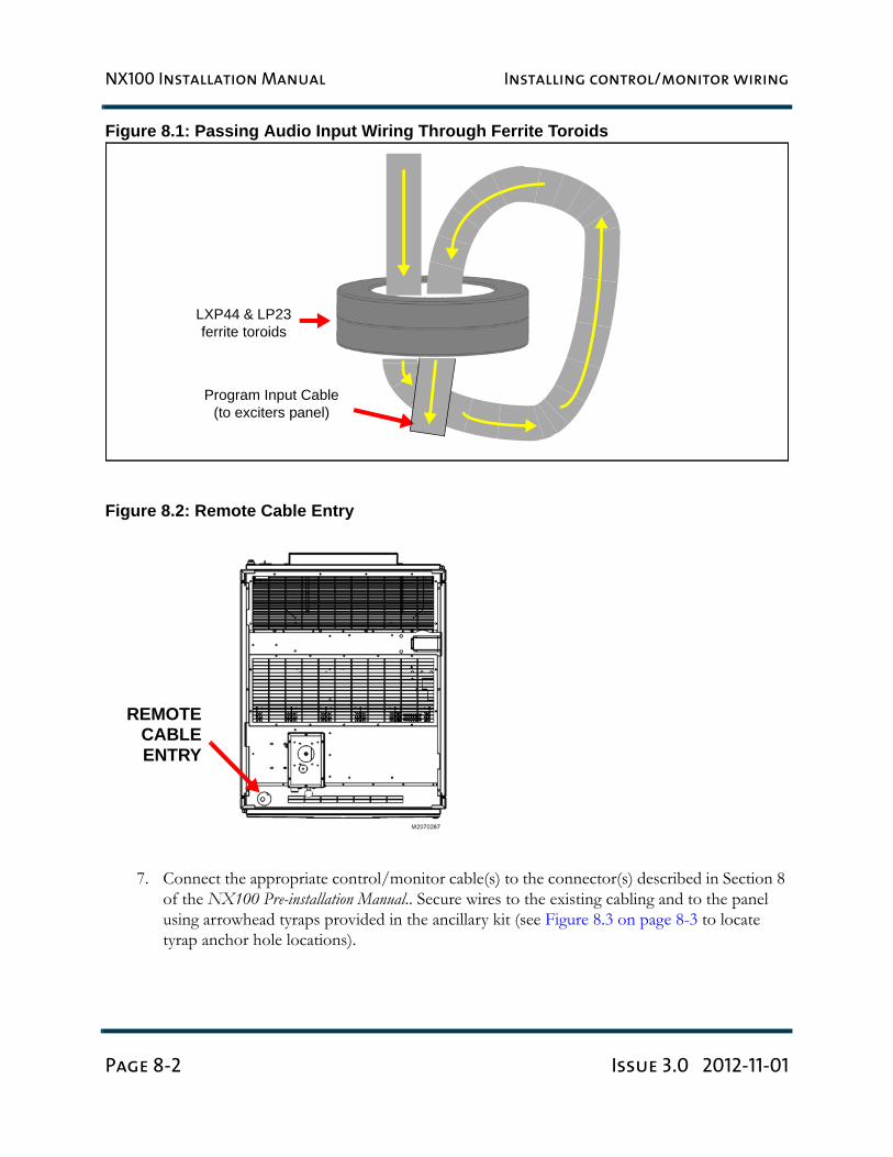
Figure 8.1: Passing Audio Input Wiring Through Ferrite Toroids
Figure 8.2: Remote Cable Entry
7. Connect the appropriate control/monitor cable(s) to the connector(s) described in Section 8 of the NX100 Pre-installation Manual.. Secure wires to the existing cabling and to the panel using arrowhead tyraps provided in the ancillary kit (see Figure 8.3 on page 8-3 to locate tyrap anchor hole locations).
Program Input Cable(to exciters panel)
LXP44 & LP23 ferrite toroids
REMOTECABLEENTRY
NX100 Installation Manual Installing control/monitor wiring
Issue 3.0 2012-11-01 Page 8-3
Figure 8.3: Remote Interface Connections
A4 - REMOTEINTERFACE PWB
Arrowhead tyrapanchor holes
External +15V IN
Analog Outputs
Digital Inputs
DigitalOutputs
External System Interlock andPDM Inhibit connections, as applicable
NX100 Installation Manual Installing control/monitor wiring
Page 8-4 Issue 3.0 2012-11-01
Figure 8.4: Web Interface Connection
ETHERNETCABLE ENTRY
Secure to existing cable with tyraps
Connect to left-hand (LAN1) connector (nearest the D-sub connectors)
NX100 Installation Manual Commissioning tasks
Issue 3.0 2012-11-01 Page 9-1
Section 9: Commissioning tasks
The transmitter contains solid-state devices that may be damaged if subjected to excessive heat or high-voltage transients. Ensure that circuits are not overdriven or disconnected from their loads while turned on.
The transmitter was precisely calibrated and tested during manufacturing. Do not change any adjustments other than those specified
Pre-commissioning tasks
1. Confirm the ac power source's nominal, loaded, phase-to-phase, rms voltage.
2. Ensure that ac power source is switched off at the safety interlock switch.
3. Identify which primary winding taps should be used and connected to the transformer's ac power input (Line) terminals. See Table 4.1 on page 4-2.
4. Confirm that the taps are configured correctly.
5. Remove the rear filters from the ttransmitter and spray them with filter coat adhesive spray (Nautel Part # HQ59), located in the ancillary kit. Re-install the rear filters on the transmitter.
6. Terminate the transmitter's RF output into a precision, 50 Ω, resistive dummy load that is able to dissipate the RF power being applied to it: 150 kW total required.
WARNING: Before applying ac power and turning on the transmitter,
you must customize some circuits to the station's power source and
operating requirements. Do not perform this pre-commissioning
unless you are a station engineer or a competent electronics
technician.
WARNING: If you do not observe this precaution, you could be
seriously injured or killed by the voltages on the circuit breaker and
the transformer terminals.
NX100 Installation Manual Commissioning tasks
Page 9-2 Issue 3.0 2012-11-01
7. Verify that all panels are installed, and ensure that their attaching hardware is firmly tightened.
8. Connect the dummy load’s interlock or, if necessary, simulate the closing of all external interlocks. This requires a short circuit between J6-1 and J6-2 of the control/interface PWB. Ensure all networks connected to the transmitter’s RF output are properly covered.
9. In lieu of normal station programming, connect an analog audio signal generator, preset to 1000 Hz at a zero output level (turned off), to connector J12 on the control/interface PWB, or an AES signal generator to connector J11 on the control/interface PWB.
Commissioning
Turning on the transmitter
1. Switch on the ac power at the service entrance to turn on the transmitter.
2. Check the alarm and status indications on the control cabinet’s AUI using the Transmitter Status page of the AUI.
3. Check the output of the +5, +15 and -15 V power supplies on the AUI (click Meters, then select Rack 1 and the appropriate power supply).
4. Check the ac sample voltage on the AUI (click Meters, then select Rack 1 and then select AC Sample). It should be between 310 V and 335 V. If not, change the transformer tap setting (see Section 3, “Installing the power transformer” on page 3-1).
5. Select Local control.
6. Set the active preset’s power output to zero.
7. Press RF On. The RF On button will turn green.
WARNING:
If a jumper is placed between interlock inputs J6-1/2 on the control/
interface pwb, safety features controlled by the external interlocks
will be disabled. A fail safe method of alerting personnel to this fact
should be implemented. Voltages which are dangerous to life will be
present on the RF output stages and the antenna system if the
transmitter is turned on.
NX100 Installation Manual Commissioning tasks
Issue 3.0 2012-11-01 Page 9-3
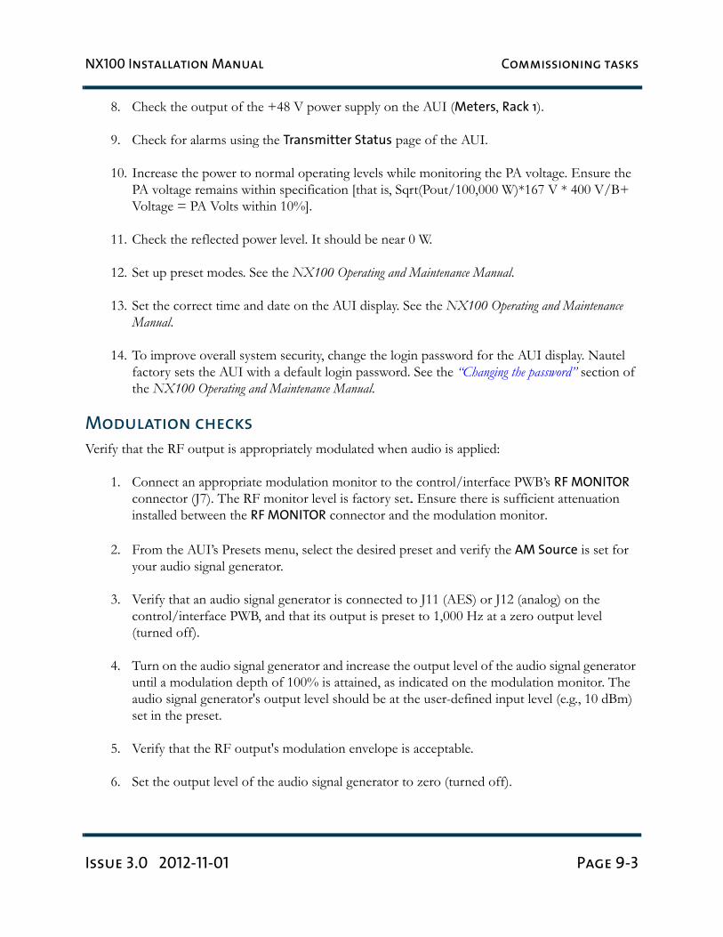
8. Check the output of the +48 V power supply on the AUI (Meters, Rack 1).
9. Check for alarms using the Transmitter Status page of the AUI.
10. Increase the power to normal operating levels while monitoring the PA voltage. Ensure the PA voltage remains within specification [that is, Sqrt(Pout/100,000 W)*167 V * 400 V/B+ Voltage = PA Volts within 10%].
11. Check the reflected power level. It should be near 0 W.
12. Set up preset modes. See the NX100 Operating and Maintenance Manual.
13. Set the correct time and date on the AUI display. See the NX100 Operating and Maintenance Manual.
14. To improve overall system security, change the login password for the AUI display. Nautel factory sets the AUI with a default login password. See the “Changing the password” section of the NX100 Operating and Maintenance Manual.
Modulation checks
Verify that the RF output is appropriately modulated when audio is applied:
1. Connect an appropriate modulation monitor to the control/interface PWB’s RF MONITOR connector (J7). The RF monitor level is factory set.. Ensure there is sufficient attenuation installed between the RF MONITOR connector and the modulation monitor.
2. From the AUI’s Presets menu, select the desired preset and verify the AM Source is set for your audio signal generator.
3. Verify that an audio signal generator is connected to J11 (AES) or J12 (analog) on the control/interface PWB, and that its output is preset to 1,000 Hz at a zero output level (turned off).
4. Turn on the audio signal generator and increase the output level of the audio signal generator until a modulation depth of 100% is attained, as indicated on the modulation monitor. The audio signal generator's output level should be at the user-defined input level (e.g., 10 dBm) set in the preset.
5. Verify that the RF output's modulation envelope is acceptable.
6. Set the output level of the audio signal generator to zero (turned off).
NX100 Installation Manual Commissioning tasks
Page 9-4 Issue 3.0 2012-11-01
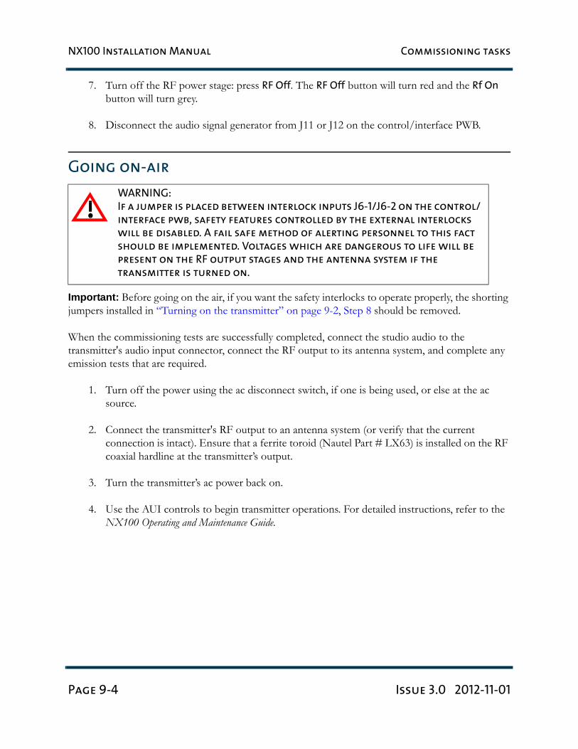
7. Turn off the RF power stage: press RF Off. The RF Off button will turn red and the Rf On button will turn grey.
8. Disconnect the audio signal generator from J11 or J12 on the control/interface PWB.
Going on-air
Important: Before going on the air, if you want the safety interlocks to operate properly, the shorting jumpers installed in “Turning on the transmitter” on page 9-2, Step 8 should be removed.
When the commissioning tests are successfully completed, connect the studio audio to the transmitter's audio input connector, connect the RF output to its antenna system, and complete any emission tests that are required.
1. Turn off the power using the ac disconnect switch, if one is being used, or else at the ac source.
2. Connect the transmitter's RF output to an antenna system (or verify that the current connection is intact). Ensure that a ferrite toroid (Nautel Part # LX63) is installed on the RF coaxial hardline at the transmitter’s output.
3. Turn the transmitter’s ac power back on.
4. Use the AUI controls to begin transmitter operations. For detailed instructions, refer to the NX100 Operating and Maintenance Guide.
WARNING:
If a jumper is placed between interlock inputs J6-1/J6-2 on the control/
interface pwb, safety features controlled by the external interlocks
will be disabled. A fail safe method of alerting personnel to this fact
should be implemented. Voltages which are dangerous to life will be
present on the RF output stages and the antenna system if the
transmitter is turned on.
NX100 Installation Manual Parts and tools
Issue 3.0 2012-11-01 Page 10-1
Section 10: Parts and tools
This section describes parts associated with the NX100 transmitter, and tools needed during installation and routine operation. Topics include:
• Parts supplied by Nautel
• Parts not supplied by Nautel - see page 10-2
• Parts ordering - see page 10-2
• Module replacement program - see page 10-2
• Tools for installation - see page 10-3
Contacting Nautel
You can reach Nautel to order parts or for technical assistance at:
Nautel Limited10089 Peggy’s Cove RoadHackett’s Cove, NS Canada B3Z 3J4Phone: +1.877.628.8353 (Canada/US) +1.902.823.5100 (International)
Fax: +1.902.823.3183
Email: [email protected]
Web: www.nautel.com
Parts supplied by Nautel
Ancillary parts kit
An ancillary parts kit is shipped with the NX100. This kit contains hardware needed during the installation process. The kit includes toroids, spare fuses, screws and other miscellaneous hardware.
NX100 Installation Manual Parts and tools
Page 10-2 Issue 3.0 2012-11-01
Documentation
See “NX300 transmitter manuals” on page xii.
Parts not supplied by Nautel
Some parts and materials required to complete installation are not supplied by Nautel. The parts you need vary with the installation requirements. The list of parts you normally provide yourself during installation include:
• A suitable 50 Ω RF output coaxial cable, terminated by the proper connector, complete with center male connector at the transmitter end.
• All external control and monitor wiring, including the associated terminating devices, con-duit and conduit clamps.
• All electrical power cables, including conduit, terminating devices, and conduit clamps.
Parts ordering
You can order replacement parts from your Nautel sales agent, or directly from Nautel through the Nautel website.
Module replacement program
Nautel offers a module replacement program for customers who require expedited servicing and replacement of faulty modules. The module replacement program provides immediate replacement of failed modules with refurbished modules.
• The replacement module is shipped to the customer as soon as the customer reports the failure. The customer then returns the failed module to Nautel using the same shipping package.
NX100 Installation Manual Parts and tools
Issue 3.0 2012-11-01 Page 10-3
Tools for installation
The tools you need during transmitter installation include the following:
• Digital voltmeter
• Philips screwdrivers, sizes #1 and #2
• Pliers
• Wire cutters
• Slot screwdriver, 5 mm (3/16 inch)
• Metric and Imperial socket set up to 24 mm (15/16 inch)
• Metric and Imperial wrench set up to 25 mm (1 inch)
• Feeler gauge (to measure spark gap)
• Torque wrench (capable of up to 275 in-lbs or 31 N-m)

NX100 Installation Manual Parts and tools
Page 10-4 Issue 3.0 2012-11-01
NX100 Installation Manual Pre-installation / Installation assistance
Issue 3.0 2012-11-01 Page 11-1
Section 11: Pre-installation / Installation
assistance
Nautel provides a number of support options to help you during pre-installation planning and preparation:
• Pre-installation consulting
• Installation and commissioning service
• Online documentation - see page 11-3
• On-site support - see page 11-3
• Training - see page 11-3
• Standard warranty - see page 11-4
• Extended warranties - see page 11-7
Pre-installation consulting
Nautel field support specialists are available to answer questions and work with you to ensure that yoursite will be ready for the installation of your NX100 transmitter. For support, contact Nautel CustomerService and request assistance (“On-site support” on page 11-3).
Installation and commissioning service
Nautel offers an installation and commissioning service to customers who want assistance with configuring and commissioning a new Nautel transmitter. After the customer completes the transmitter assembly and installation, Nautel technical personnel will spend up to three days on-site to help make the ac power, RF and remote connections, and to assist with the configuration and testing of Nautel equipment.
The customer is responsible for ensuring that the following stages of installation have been completed, prior to the arrival of Nautel personnel:
NX100 Installation Manual Pre-installation / Installation assistance
Page 11-2 Issue 3.0 2012-11-01
• Ac power wiring for the transmitter has been installed and connected at the breaker panel or the building’s service entrance. If local electrical codes allow Nautel personnel to connect the transmitter to the ac supply, using the customer's cable, that task is included in this service. Otherwise, the customer must ensure that an approved electrician is present for this task.
• The customer has prepared the RF coaxial cable – used to connect the transmitter to the antenna – and installed the required connector. The customer has also installed the RF coax-ial cable in place and connected it to the antenna, while leaving the transmitter end of the cable unconnected.
• Where required, all remote control and monitoring cables have been installed and connected to the station equipment (e.g., modulation monitor, frequency monitor, and power meter).
• The site has been made ready for the equipment, and adequate protection against lightning and lightning-induced transients has been provided.
• The transmitter has been unpacked, closely checked for any damage caused by shipping, and then assembled.
• The following test equipment has been made available at the site:
– Two-channel oscilloscope (with probes)
– Audio signal generator
– Distortion analyzer
– Spectrum analyzer
– Modulation monitor
– Frequency counter
– 50 Ω test load (rated for 150% of carrier power, VSWR less than 1.1:1)
Nautel’s service representative takes full responsibility for commissioning the transmitter, validating all external interfaces (i.e., the ac supply, RF output, remote control and monitoring equipment) and checking out the equipment prior to activation. The service representative turns on the transmitter, performs all adjustments and set-up procedures, and carries out proof of performance tests at the site.
NX100 Installation Manual Pre-installation / Installation assistance
Issue 3.0 2012-11-01 Page 11-3
These tests ensure that the transmitter is operating normally in compliance with its specifications. The service representative also provides a demonstration and a short explanation of the operation of the transmitter. Finally, the customer signs an Acceptance of Installation Certificate that provides feedback to Nautel regarding the commissioning service.
Online documentation
Nautel provides documentation online to customers, letting you familiarize yourself withspecifications, operation, maintenance and troubleshooting prior to the delivery of your equipment.(Documentation is also provided on CDROM and in paper binders that are delivered with thetransmitter.)
On-site support
If you require on-site assistance, Nautel’s field support specialists can help you prepare your site and ensure that your NX100 transmitter installation can proceed as quickly as possible. For more information about on-site support, including scheduling and pricing, contact Nautel Customer Service:
• Telephone: +1.902.823.5100
• Fax: +1.902.823.3183
• Email: [email protected]
After business hours (Atlantic time or Eastern time in North America), requests sent by fax or emailwill be acknowledged within one working day.
Training
Nautel's SBE-certified broadcast training programs satisfy your day-to-day knowledge requirements. Students participating in Nautel's broadcast transmitter or RF basics training programs earn one SBE credit for each completed day of training.
Nautel’s comprehensive selection of training programs will help customer staff develop valuable skill sets, reduce downtime, and make the most of the customer’s technology investment.
NX100 Installation Manual Pre-installation / Installation assistance
Page 11-4 Issue 3.0 2012-11-01
Nautel training programs are made up of individual modules that can be 'mixed and matched' to meet the customer’s specific training needs. All Nautel training courses are available at the Nautel Training Center. Training can also be provided at the customer’s facility, and training the customer’s technical staff on the customer’s transmitter.
All training courses at the Nautel Training Centre combine classroom and hands-on laboratory work to ensure a balanced learning experience.
Nautel training courses feature:
• Limited class sizes to ensure maximum student participation and access to equipment
• Emphasis on need-to-know, day-to-day knowledge
• Labs that focus on the tasks most often performed at the transmitter site.
Many of our classes also include diagnostic lab exercises.
Standard warranty
Nautel Limited/Nautel Incorporated, hereinafter referred to as Nautel, guarantees all mechanical and electrical parts of the equipment for a period of 13 months from date of shipment.
1. A "Part Failure" shall be deemed to have occurred when the part has become defective, or does not have the characteristics required for the specified equipment performance:
(a) When the equipment is operated within the design parameters, and
(b) When the equipment is installed and adjusted according to Nautel's prescribed procedures as stated in the instruction manual.
2. Nautel shall provide replacements for all "Parts" at no cost to the Customer when they become defective during the warranty period, and upon the return of the defective part.
3. In the event that a "Part" fails during the warranty period and causes damage to a sub-assembly that cannot be readily repaired in the field, the entire sub-assembly so damaged may be returned to Nautel for repair. The repairs will be made without charge to the Customer.
4. Where warranty replacements or repair are provided under items 2 or 3, Nautel will pay that part of the shipping costs incurred in returning the part/assembly to the Customer.
NX100 Installation Manual Pre-installation / Installation assistance
Issue 3.0 2012-11-01 Page 11-5
5. Warranty replacement parts and repair, which are provided under items 2 or 3, shall be guaranteed for a period of ninety days from date of shipment or until the end of the original warranty period, whichever occurs later.
6. Nautel will not assume responsibility for any charges incurred by other than Nautel employees.
7. Nautel shall have the privilege of investigating whether failures have been caused by factors beyond its control.
8. Nautel shall in no event be liable for any consequential damages arising from the use of this equipment.
9. When requesting a warranty repair/replacement, please provide complete and accurate information. Observe the instructions regarding “Equipment being returned to Nautel” on page 11-6 and provide the information requested.
10. When ordering spare/replacement parts, please provide complete and accurate information. Refer to the parts list of the Repair manual for ordering information. Provide as much of the information requested for 'Equipment Being Returned to Nautel' on page two of this warranty as is practical. The information identified by an asterisk is the minimum required.
Technical assistance
Nautel's field service department provides telephone technical assistance on a 24 hour, seven days a week basis. Requests by other media (fax or e-mail) will be responded to the next working day if received after Nautel's normal working hours. Contact the appropriate field service centre:
Nautel Limited10089 Peggy’s Cove RoadHackett’s Cove, NS Canada B3Z 3J4Phone: +1.902.823.3900 orToll Free: +1.877.6NAUTEL (6628835) (Canada & USA only)Fax: +1.902.823.3183
Nautel Inc. 201 Target Industrial Circle Bangor, Maine USA 04401 Phone: +1.207.947.8200 Fax: +1.207.947.3693
Customer Service (24 hour support) +1.877.628.8353 (Canada & USA only)
NX100 Installation Manual Pre-installation / Installation assistance
Page 11-6 Issue 3.0 2012-11-01
+1.902.823.5100 (International)
Email: [email protected]: www.nautel.comModule exchange service
In order to provide Nautel customers with a fast and efficient service in the event of a problem, Nautel operates a factory rebuilt, module exchange service which takes full advantage of the high degree of module redundancy in Nautel equipment. This module exchange service is operated from Nautel's factory in Bangor, Maine and Hackett's Cove, Nova Scotia. These two locations allow us to provide a quick turn around service to keep our customers on the air. During the transmitter's warranty period, up to thirteen months from shipment, repair and exchange of modules is at no charge to the customer. When the warranty has expired, a charge of 80% of the list price for all exchanged modules is made. If the faulty module is returned to Nautel within 30 days, a credit is issued reducing this charge by one half to 40% of the list price. USA customers are required to contact our Bangor, Maine facility. Canadian and overseas customers should contact our Nova Scotia, Canada facility.
Equipment being returned to Nautel
For all equipment being returned to Nautel and all requests for repairs or replacements:
• Obtain an RMA number from Nautel (you must have an RMA number to return equipment)
• Mark the item as 'field return'
• Mark the item with the RMA number assigned by Nautel
• Address the item to the appropriate Nautel facility
Complete and accurate information regarding the equipment being returned will ensure prompt attention and will expedite the dispatch of replacements. Refer to the nameplate on the transmitter and/or the appropriate module/assembly to obtain name, type, part and serial number information. Refer to the parts list of this manual or the appropriate service instruction manual for additional ordering information.
The following information should accompany each request (* denotes minimum required information):
• *Model and serial number of equipment
• *Name of part/assembly
NX100 Installation Manual Pre-installation / Installation assistance
Issue 3.0 2012-11-01 Page 11-7
• Serial number of part/assembly
• *Complete reference designation of part/assembly
• *Nautel's part number of part/assembly
• *OEM's part number of part/assembly
• Number of hours in use
• Nature of defect
• *Return shipping address
Extended warranties
Nautel's standard 13-month warranty provides excellent coverage and satisfies most customers’ needs. However, if you want extended coverage, Nautel offers one and two-year Extended Warranty Plans to cover electrical and mechanical repairs or replacements for all Nautel equipment.
Coverage
The Extended Warranty Plan includes:
• A module exchange program for many common modules and circuit boards (North America only)
• Toll-free hotline (North America only)
• Necessary labor performed by Nautel authorized personnel to repair the product back to factory specifications
• Necessary components
• Modifications to correct performance problems
• Return shipping.
Details
Extended Warranty Plans must be purchased prior to the expiration of original 13-month warranty.
NX100 Installation Manual Pre-installation / Installation assistance
Page 11-8 Issue 3.0 2012-11-01
One-year Extended Warranty Plans add an additional year (12 months) of coverage after the end of the customer’s standard 13-month warranty. The two-year plan adds an additional two years (24 months).
Only repairs done at Nautel's facilities or by Nautel authorized personnel will be covered by the Extended Warranty Plans.
You must ship faulty products back to Nautel, prepaid, and in the original package or in a package that provides equivalent protection.
Nautel can choose to repair or replace equipment.
Purchasing a one or two-year Extended Warranty Plan
If the transmitter is still covered by its original 13-month warranty period, you can contact Nautel by telephone, fax, mail, or email with the model number, serial number and date of purchase.
Once you purchase a Nautel Extended Warranty Plan, you receive an extended warranty plan certificate, plan number, and a toll-free number (North America only) to call for any service-related issues.
Using the Extended Warranty Plan
Contact Nautel's Canadian or U.S. service facility by phone, fax, or email as soon as a problem occurs. The following will be required when contacting Nautel:
• Extended warranty plan number
• Product model number
• Serial number
• Brief description of the problem
If Nautel’s service technicians are unable to solve the problem over the telephone, Nautel will give you an RMA number. You then return the module or circuit board to a Nautel service facility so that Nautel can provide a replacement. (Do not ship a component back to Nautel until you have an RMA number.)
NX100 Installation Manual List of terms
Issue 3.0 2012-11-01 Page 12-1
Section 12: List of terms
This section defines some of the terms that are used in Nautel documentation.
ADC. Analog to Digital Converter.
AES-EBU. Audio Engineering Society/European Broadcasting Union (AES/EBU) is the name of a digital audio transfer standard. The AES/EBU digital interface is usually implemented using 3-pin XLR connectors (the same type connector used in professional microphones). One cable carries both left and right-channel audio data to the receiving device.
B+. The high voltage dc generated by the transmitter’s ac power supply for use within the transmitter. The B+ voltage is used to supply the transmitter’s modulators and other transmitter circuitry.
Cutback. A reduction in RF output power, caused by a total power limit fault or the occurrence of three shutbacks within a five second period.
DAC. Digital to Analog Converter.
DAM. Dynamic Amplitude Modulation.
DCC. Dynamic Carrier Control.
DRM. Digital Radio Mondiale. A set of digital audio broadcasting technologies designed to work existing AM radio channels.
DSP. Digital Signal Processing.
FPGA. Field Programmable Gate Array.
HD Radio. HD Radio is another term for In Band On Channel (IBOC) technology. HD Radio is a trademark of iBiquity Digital Corporation.
IBOC. Nautel In-Band-On-Channel technology provides high quality digital audio over existing AM radio channels.
IPM. Incidental Phase Modulation
Latching alarm. An alarm that, while active, keeps the transmitter in an ‘RF inhibited’ state. This type of alarm (e.g., High SWR Shutdown) require a reset - locally or remotely - to attempt to restore transmitter operation.
NX100 Installation Manual List of terms
Page 12-2 Issue 3.0 2012-11-01
NE IBOC. Nautel’s In-Band-On-Channel signal generator. See IBOC. Required for NX series IBOC installations.
PDM. Pulse Duration Modulation.
Preset. A setting that controls power level, active exciter, and power scheduler status on a time-of-day and date basis. Exciters can be configured on a preset for a specific operating mode (for example, Exciter A - conventional AM, and Exciter B - IBOC). The NX100 allows you to pre-program multiple presets.
Shutback. A complete loss of RF output power, caused by any one of a variety of faults, including high VSWR, low B+ voltage, high RF current, RF drive failure, external interlock or spark gap.
Surge protection board. An electrical panel that protects equipment from electrical surges in the ac power supply, antenna or site ground caused by lightning strikes.
VSWR. Voltage standing wave ratio. This is an expression of the ratio of forward voltage to reverse voltage on the feedline and antenna system. An ideal VSWR of 1:1 provides maximum transmitter-antenna efficiency.


NX100 INSTALLATION MANUAL
Document: NHB-NX100-INS
Issue: 3.0 2012-11-01
Nautel Limited10089 Peggy’s Cove RoadHackett’s Cove, NS Canada B3Z 3J4
Toll Free: +1.877.6NAUTEL (662.8835) (Canada & USA only) or
Phone: +1.902.823.3900 orFax: +1.902.823.3183
Nautel Inc. 201 Target Industrial Circle Bangor, Maine USA 04401
Phone: +1.207.947.8200 Fax: +1.207.947.3693
Customer Service (24-hour support) +1.877.628.8353 (Canada & USA only)+1.902.823.5100 (International)
Email: [email protected]: www.nautel.com
© Copyright 2013 NAUTEL. All rights reserved.


![[Review of NX100 + 20-50mm lens] Performance of the NX100](https://img.pdfslide.net/doc/110x75/568bef531a28ab89338bc1ae/review-of-nx100-20-50mm-lens-performance-of-the-nx100-56e22b1aa4607.jpg)