Embed Size (px)
Citation preview

Motoman NX100 Controller
EPL500 ManipulatorManual
Part Number: 150776-1CDRevision: 0
Motoman, Incorporated 805 Liberty LaneWest Carrollton, OH 45449TEL: (937) 847-6200FAX: (937) 847-627724-Hour Service Hotline: (937) 847-3200

The information contained within this document is the proprietary property of Motoman, Inc., and may not be copied, reproduced or transmitted to other parties without the expressed written authorization of Motoman,
Inc.
©2007 by MOTOMANAll Rights Reserved
Because we are constantly improving our products, we reserve the right to change specifications without notice. MOTOMAN is a registered trademark of YASKAWA Electric Manufacturing.
COMPLETE OUR ONLINE SURVEYMotoman is committed to total customer satisfaction! Please give us your feedback on the technical manuals you
received with your Motoman robotic solution.
To participate, go to the following website:
http://www.motoman.com/forms/techpubs.asp
EPL500150776-1
Chapter 1
Introduction
1.1 About This Document
This manual provides information for the EPL500 manipulator and contains the following chapters:
CHAPTER 1 - INTRODUCTIONProvides general information about the structure of this manual, a list of reference documents, and customer service information.
CHAPTER 2 - SAFETYThis section provides information regarding the safe use and operation of Motoman products.
CHAPTER 3 - EPL500 INSTRUCTIONSProvides detailed instructions for the EPL500.
1.2 Reference to Other Documentation
For additional information refer to the following:
• NX100 Controller Manual (P/N 149201-1)
• Concurrent I/O Manual (P/N 149230-1)
• Operator’s Manual for your application
• Vendor manuals for system components not manufactured by Motoman
1.3 Customer Service Information
If you are in need of technical assistance, contact the Motoman service staff at (937) 847-3200. Please have the following information ready before you call:
• Robot Type (EPL500, HP50, etc.)
• Application Type (handling, welding, etc.)
• Robot Serial Number (located on back side of robot arm)
• Robot Sales Order Number (located on back of controller)
Final page 1

Manipulator Manual Chapter 1 Introduction
Notes
page 2 Final
EPL500150776-1
Chapter 2
Safety
2.1 Introduction
It is the purchaser’s responsibility to ensure that all local, county, state, and national codes, regulations, rules, or laws relating to safety and safe operating conditions for each installation are met and followed.
We suggest that you obtain and review a copy of the ANSI/RIA National Safety Standard for Industrial Robots and Robot Systems. This information can be obtained from the Robotic Industries Association by requesting ANSI/RIA R15.06-1999. The address is as follows:
Robotic Industries Association900 Victors WayP.O. Box 3724
Ann Arbor, Michigan 48106TEL: (734) 994-6088FAX: (734) 994-3338
INTERNET: www.roboticsonline.com
Ultimately, the best safeguard is trained personnel. The user is responsible for providing personnel who are adequately trained to operate, program, and maintain the robot cell. The robot must not be operated by personnel who have not been trained!
We recommend that all personnel who intend to operate, program, repair, or use the robot system be trained in an approved Motoman training course and become familiar with the proper operation of the system.
Final page 3
Manipulator Manual Chapter 2 Safety
This safety section addresses the following:
• Standard Conventions (Section 2.2)
• General Safeguarding Tips (Section 2.3)
• Mechanical Safety Devices (Section 2.4)
• Installation Safety (Section 2.5)
• Programming, Operation, and Maintenance Safety (Section 2.6)
2.2 Standard Conventions
This manual includes the following alerts – in descending order of severity – that are essential to the safety of personnel and equipment. As you read this manual, pay close attention to these alerts to insure safety when installing, operating, programming, and maintaining this equipment.
DANGER!Information appearing in a DANGER concerns the protection of personnel from the immediate and imminent hazards that, if not avoided, will result in immediate, serious personal injury or loss of life in addition to equipment damage.
WARNING!Information appearing in a WARNING concerns the protection of personnel and equipment from potential hazards that can result in personal injury or loss of life in addition to equipment damage.
CAUTION!Information appearing in a CAUTION concerns the protection of personnel and equipment, software, and data from hazards that can result in minor personal injury or equipment damage.
Note: Information appearing in a Note provides additional information which is helpful in understanding the item being explained.
page 4 Final
EPL500150776-1
2.3 General Safeguarding Tips
All operators, programmers, plant and tooling engineers, maintenance personnel, supervisors, and anyone working near the robot must become familiar with the operation of this equipment. All personnel involved with the operation of the equipment must understand potential dangers of operation. General safeguarding tips are as follows:
• Improper operation can result in personal injury and/or damage to the equipment. Only trained personnel familiar with the operation of this robot, the operator's manuals, the system equipment, and options and accessories should be permitted to operate this robot system.
• Do not enter the robot cell while it is in automatic operation. Programmers must have the teach pendant when they enter the robot cell.
• Improper connections can damage the robot. All connections must be made within the standard voltage and current ratings of the robot I/O (Inputs and Outputs).
• The robot must be placed in Emergency Stop (E-STOP) mode whenever it is not in use.
• In accordance with ANSI/RIA R15.06-1999, section 4.2.5, Sources of Energy, use lockout/tagout procedures during equipment maintenance. Refer also to Section 1910.147 (29CFR, Part 1910), Occupational Safety and Health Standards for General Industry (OSHA).
2.4 Mechanical Safety Devices
The safe operation of the robot, positioner, auxiliary equipment, and system is ultimately the user's responsibility. The conditions under which the equipment will be operated safely should be reviewed by the user. The user must be aware of the various national codes, ANSI/RIA R15.06-1999 safety standards, and other local codes that may pertain to the installation and use of industrial equipment. Additional safety measures for personnel and equipment may be required depending on system installation, operation, and/or location. The following safety equipment is provided as standard:
• Safety fences and barriers
• Light curtains and/or safety mats
• Door interlocks
• Emergency stop palm buttons located on operator station, robot controller, and programming pendant
Check all safety equipment frequently for proper operation. Repair or replace any non-functioning safety equipment immediately.
Final page 5

Manipulator Manual Chapter 2 Safety
2.5 Installation Safety
Safe installation is essential for protection of people and equipment. The following suggestions are intended to supplement, but not replace, existing federal, local, and state laws and regulations. Additional safety measures for personnel and equipment may be required depending on system installation, operation, and/or location. Installation tips are as follows:
• Be sure that only qualified personnel familiar with national codes, local codes, and ANSI/RIA R15.06-1999 safety standards are permitted to install the equipment.
• Identify the work envelope of each robot with floor markings, signs, and barriers.
• Position all controllers outside the robot work envelope.
• Whenever possible, install safety fences to protect against unauthorized entry into the work envelope.
• Eliminate areas where personnel might get trapped between a moving robot and other equipment (pinch points).
• Provide sufficient room inside the workcell to permit safe teaching and maintenance procedures.
2.6 Programming, Operation, and Maintenance Safety
All operators, programmers, plant and tooling engineers, maintenance personnel, supervisors, and anyone working near the robot must become familiar with the operation of this equipment. Improper operation can result in personal injury and/or damage to the equipment. Only trained personnel familiar with the operation, manuals, electrical design, and equipment interconnections of this robot should be permitted to program, operate, and maintain the system. All personnel involved with the operation of the equipment must understand potential dangers of operation.
• Inspect the robot and work envelope to be sure no potentially hazardous conditions exist. Be sure the area is clean and free of water, oil, debris, etc.
• Be sure that all safeguards are in place. Check all safety equipment for proper operation. Repair or replace any non-functioning safety equipment immediately.
• Do not enter the robot cell while it is in automatic operation. Be sure that only the person holding the programming pendant enters the workcell.
• Check the E-STOP button on the programming pendant for proper operation before programming. The robot must be placed in Emergency Stop (E-STOP) mode whenever it is not in use.
• Back up all programs and jobs onto suitable media before program changes are made. To avoid loss of information, programs, or jobs, a backup must always be made before any service procedures are done and before any changes are made to options, accessories, or equipment.
page 6 Final

EPL500150776-1
• Any modifications to PART 1, System Section, of the robot controller concurrent I/O program can cause severe personal injury or death, as well as damage to the robot! Do not make any modifications to PART 1, System Section. Making any changes without the written permission of Motoman will VOID YOUR WARRANTY!
• Some operations require standard passwords and some require special passwords. Special passwords are for Motoman use only. YOUR WARRANTY WILL BE VOID if you use these special passwords.
• The robot controller allows modifications of PART 2, User Section, of the concurrent I/O program and modifications to controller parameters for maximum robot performance. Great care must be taken when making these modifications. All modifications made to the controller will change the way the robot operates and can cause severe personal injury or death, as well as damage the robot and other parts of the system. Double-check all modifications under every mode of robot operation to ensure that you have not created hazards or dangerous situations.
• Check and test any new or modified program at low speed for at least one full cycle.
• This equipment has multiple sources of electrical supply. Electrical interconnections are made between the controller and other equipment. Disconnect and lockout/tagout all electrical circuits before making any modifications or connections.
• Do not perform any maintenance procedures before reading and understanding the proper procedures in the appropriate manual.
• Use proper replacement parts.
• Improper connections can damage the robot. All connections must be made within the standard voltage and current ratings of the robot I/O (Inputs and Outputs).
Final page 7

Manipulator Manual Chapter 2 Safety
Notes
page 8 Final

YASKAWA
MOTOMANINSTRUCTITYPE: YR-EPL500-ATYPE: YR-EPL500-A
Upon receipt of the producfor future reference.
MOTOMAN INSTRUCTIOMOTOMAN-EPL500 INSNX100 INSTRUCTIONSNX100 OPERATOR’S MNX100 MAINTENACE M
The NX100 operator’s manualBe sure to use the appropriate
YASKAWA
-EPL500
ONS00 (STANDARD SPECIFICATION)10 (FOR INTEGRATED WRIST AXIS CABLE ROUTING PACKAGE)t and prior to initial operation, read these instructions thoroughly, and retain
NSTRUCTIONS
ANUALANUAL
above corresponds to specific usage. manual.
MANUAL NO.
HW0483366 2 1/77
HW0483366
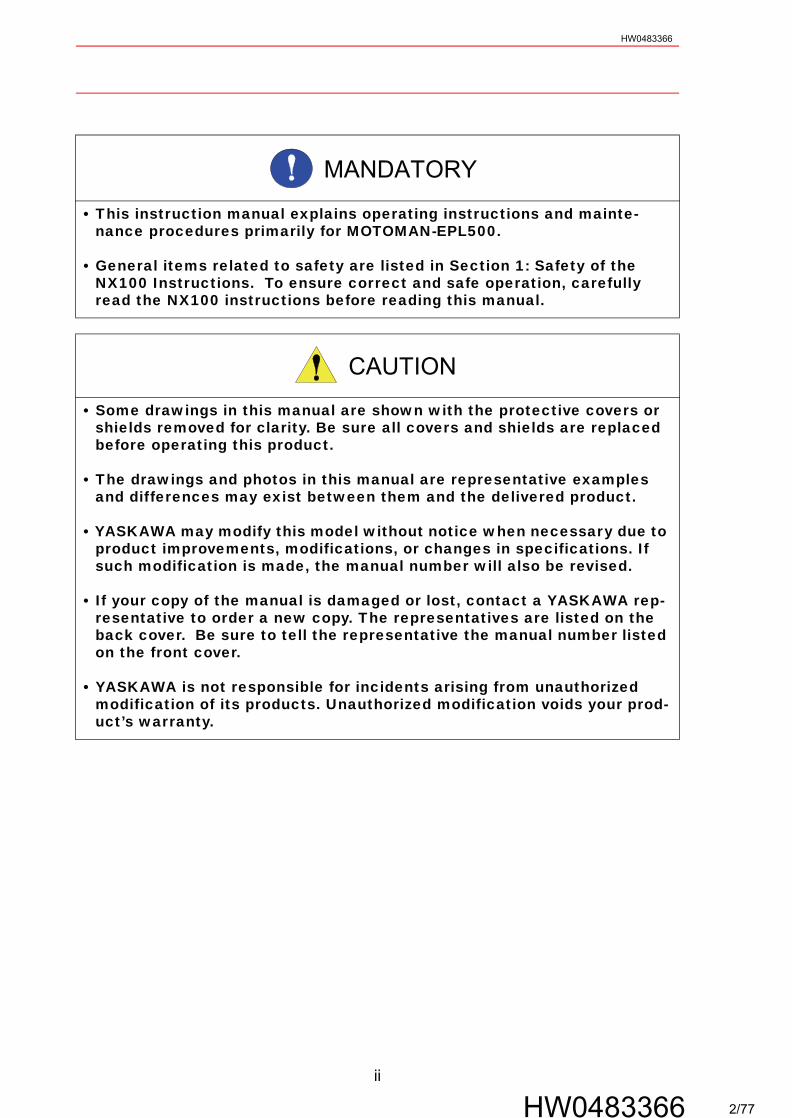
• This instruction manual explains operating instructions and mainte-nance procedures primarily for MOTOMAN-EPL500.
• General items related to safety are listed in Section 1: Safety of the NX100 Instructions. To ensure correct and safe operation, carefully read the NX100 instructions before reading this manual.
• Some drawings in this manual are shown with the protective covers or shields removed for clarity. Be sure all covers and shields are replaced before operating this product.
• The drawings and photos in this manual are representative examples and differences may exist between them and the delivered product.
• YASKAWA may modify this model without notice when necessary due to product improvements, modifications, or changes in specifications. If such modification is made, the manual number will also be revised.
• If your copy of the manual is damaged or lost, contact a YASKAWA rep-resentative to order a new copy. The representatives are listed on the back cover. Be sure to tell the representative the manual number listed on the front cover.
• YASKAWA is not responsible for incidents arising from unauthorized modification of its products. Unauthorized modification voids your prod-uct’s warranty.
MANDATORY
CAUTION
ii
HW0483366 2/77
HW0483366
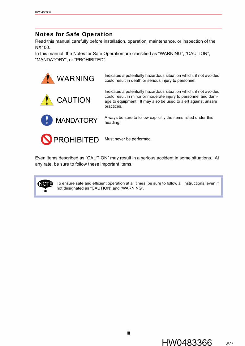
Notes for Safe OperationRead this manual carefully before installation, operation, maintenance, or inspection of the NX100. In this manual, the Notes for Safe Operation are classified as “WARNING”, “CAUTION”, “MANDATORY”, or “PROHIBITED”.
Even items described as “CAUTION” may result in a serious accident in some situations. At any rate, be sure to follow these important items.
Indicates a potentially hazardous situation which, if not avoided, could result in death or serious injury to personnel.
Indicates a potentially hazardous situation which, if not avoided, could result in minor or moderate injury to personnel and dam-age to equipment. It may also be used to alert against unsafe practices.
Always be sure to follow explicitly the items listed under this heading.
Must never be performed.
To ensure safe and efficient operation at all times, be sure to follow all instructions, even if not designated as “CAUTION” and “WARNING”.
WARNING
CAUTION
MANDATORY
PROHIBITED
NOTE
iii
HW0483366 3/77
HW0483366
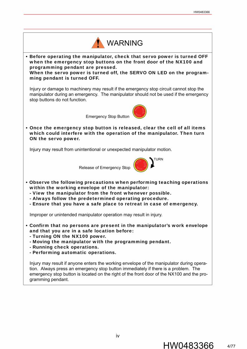
• Before operating the manipulator, check that servo power is turned OFF when the emergency stop buttons on the front door of the NX100 and programming pendant are pressed.When the servo power is turned off, the SERVO ON LED on the program-ming pendant is turned OFF.
Injury or damage to machinery may result if the emergency stop circuit cannot stop the manipulator during an emergency. The manipulator should not be used if the emergency stop buttons do not function.
Emergency Stop Button
• Once the emergency stop button is released, clear the cell of all items which could interfere with the operation of the manipulator. Then turn ON the servo power.
Injury may result from unintentional or unexpected manipulator motion.
Release of Emergency Stop
• Observe the following precautions when performing teaching operations within the working envelope of the manipulator:- View the manipulator from the front whenever possible.- Always follow the predetermined operating procedure.- Ensure that you have a safe place to retreat in case of emergency.
Improper or unintended manipulator operation may result in injury.
• Confirm that no persons are present in the manipulator’s work envelope and that you are in a safe location before:- Turning ON the NX100 power.- Moving the manipulator with the programming pendant.- Running check operations.- Performing automatic operations.
Injury may result if anyone enters the working envelope of the manipulator during opera-tion. Always press an emergency stop button immediately if there is a problem. The emergency stop button is located on the right of the front door of the NX100 and the pro-gramming pendant.
WARNING
TURN
iv
HW0483366 4/77

HW0483366
Definition of Terms Used Often in This ManualThe MOTOMAN manipulator is the YASKAWA industrial robot product.The manipulator usually consists of the controller, the programming pendant, and manipulator cables.In this manual, the equipment is designated as follows:
• Perform the following inspection procedures prior to conducting manip-ulator teaching. If problems are found, repair them immediately, and be sure that all other necessary processing has been performed.
-Check for problems in manipulator movement.-Check for damage to insulation and sheathing of external wires.
• Always return the programming pendant to the hook on the NX100 cabi-net after use.
The programming pendant can be damaged if it is left in the manipulator’s work area, on the floor, or near fixtures.
• Read and understand the Explanation of the Warning Labels in the NX100 instructions before operating the manipulator.
Equipment Manual Designation
NX100 Controller NX100
NX100 Programming Pendant Programming Pendant
Cable between the manipulator and the controller Manipulator Cable
CAUTION
v
HW0483366 5/77

HW0483366
Explanation of Warning LabelsThe following warning labels are attached to the manipulator.Always follow the warnings on the labels.Also, an identification label with important information is placed on the body of the manipula-tor. Prior to operating the manipulator, confirm the contents.
MOTOMANTYPE
PAYLOAD
ORDER NO.
SERIAL NO.
MASS
DATE
YASKAWA ELECTRIC CORPORAION JAPAN
kgkg
WARNING
Do not enterrobot work area.
Warning Label A: Warning Label B:
WARNING
Moving partsmay causeinjury
Nameplate:
WARNING
Do not enterrobot work area.
Warning label A
Warning label BNameplate
vi
HW0483366 6/77
HW0483366
1 Product Confirmation1.1 Contents Confirmation . . . . . . . . . . . . . . . . . . . . . . . . . . . . . 1-11.2 Order Number Confirmation . . . . . . . . . . . . . . . . . . . . . . . 1-2
2 Transporting2.1 Transporting Method . . . . . . . . . . . . . . . . . . . . . . . . . . . . . . 2-1
2.1.1 Using a Crane . . . . . . . . . . . . . . . . . . . . . . . . . . . . . . . . . . . . . .2-1
2.2 Shipping Bolts and Brackets . . . . . . . . . . . . . . . . . . . . . . . 2-3
3 Installation3.1 Installation of the Safeguarding . . . . . . . . . . . . . . . . . . . . 3-23.2 Mounting Procedures for Manipulator Base . . . . . . . . 3-2
3.2.1 Mounting Example. . . . . . . . . . . . . . . . . . . . . . . . . . . . . . . . . . .3-3
3.3 Location . . . . . . . . . . . . . . . . . . . . . . . . . . . . . . . . . . . . . . . . . . . 3-3
4 Wiring4.1 Grounding . . . . . . . . . . . . . . . . . . . . . . . . . . . . . . . . . . . . . . . . . 4-24.2 Manipulator Cable Connection . . . . . . . . . . . . . . . . . . . . . 4-2
4.2.1 Connection to the Manipulator. . . . . . . . . . . . . . . . . . . . . . . . . .4-34.2.2 Connection to the NX100 . . . . . . . . . . . . . . . . . . . . . . . . . . . . .4-3
5 Basic Specifications5.1 Basic Specifications . . . . . . . . . . . . . . . . . . . . . . . . . . . . . . . 5-15.2 Part Names and Working Axes . . . . . . . . . . . . . . . . . . . . 5-25.3 Manipulator Base Dimensions . . . . . . . . . . . . . . . . . . . . . 5-25.4 Dimensions and T-Point Maximum Envelope . . . . . . 5-35.5 Alterable Operating Range . . . . . . . . . . . . . . . . . . . . . . . . 5-5
5.5.1 Components for Altering Operating Range . . . . . . . . . . . . . . . .5-65.5.2 Installation of the S-Axis Mechanical Stopper . . . . . . . . . . . . . .5-75.5.3 Adjustment to the S-axis Pulse Limitation . . . . . . . . . . . . . . . . .5-8
Installation of the S-axis Mechanical Stopper at Configurable Angles . . . . . . . . . . . . . . . . . . . . . . . . . . . . . .5-10
vii
HW0483366 7/77
HW0483366
6 Allowable Load for Wrist Axis and Wrist Flange6.1 Allowable Wrist Load . . . . . . . . . . . . . . . . . . . . . . . . . . . . . . . 6-16.2 Wrist Flange . . . . . . . . . . . . . . . . . . . . . . . . . . . . . . . . . . . . . . . 6-3
7 System Application7.1 Peripheral Equipment Mounts . . . . . . . . . . . . . . . . . . . . . . 7-17.2 Internal User I/O Wiring Harness and Air Line . . . . . . 7-2
8 Electrical Equipment Specification8.1 Locations of Limit Switches. . . . . . . . . . . . . . . . . . . . . . . . . 8-18.2 Internal Connections . . . . . . . . . . . . . . . . . . . . . . . . . . . . . . . 8-2
9 Maintenance and Inspection9.1 Inspection Schedule. . . . . . . . . . . . . . . . . . . . . . . . . . . . . . . . 9-19.2 Notes on Maintenance Procedures . . . . . . . . . . . . . . . . . 9-6
9.2.1 Battery Pack Replacement . . . . . . . . . . . . . . . . . . . . . . . . . . . . 9-69.2.2 Grease Replenishment/Exchange for S-axis Speed Reducer and
Gear . . . . . . . . . . . . . . . . . . . . . . . . . . . . . . . . . . . . . . . . . . . . . 9-8 Grease Replenishment (Refer to " Fig. 24 S-axis Speed
Reducer and Gear Diagram ".) . . . . . . . . . . . . . . . . . . . . . . . 9-8 Grease Exchange (Refer to " Fig. 24 S-axis Speed Reducer and
Gear Diagram ".). . . . . . . . . . . . . . . . . . . . . . . . . . . . . . . . . . 9-99.2.3 Grease Replenishment/Exchange for L-axis Speed Reducer 9-10
Grease Replenishment (Refer to " Fig. 25 L-axis Speed Reducer Diagram ".) . . . . . . . . . . . . . . . . . . . . . . . . . . . . . . 9-10
Grease Exchange (Refer to " Fig. 25 L-axis Speed Reducer Diagram ".) . . . . . . . . . . . . . . . . . . . . . . . . . . . . . . . . . . . . . 9-12
9.2.4 Grease Replenishment/Exchange for U-axis Speed Reducer 9-13 Grease Replenishment (Refer to " Fig. 26 U-axis Speed
Reducer Diagram ".) . . . . . . . . . . . . . . . . . . . . . . . . . . . . . . 9-13 Grease Exchange (Refer to " Fig. 26 U-axis Speed Reducer
Diagram ".) . . . . . . . . . . . . . . . . . . . . . . . . . . . . . . . . . . . . . 9-149.2.5 Grease Replenishment/Exchange for T-axis Speed Reducer 9-15
Grease Replenishment (Refer to " Fig. 27 T-axis Speed Reducer Diagram ".) . . . . . . . . . . . . . . . . . . . . . . . . . . . . . . 9-16
Grease Exchange (Refer to " Fig. 27 T-axis Speed Reducer Diagram ".) . . . . . . . . . . . . . . . . . . . . . . . . . . . . . . . . . . . . . 9-16
viii
HW0483366 8/77
HW0483366
9.2.6 Grease Replenishment for U-axis Cross Roller Bearing . . . . . . . . . . . . . . . . . . . . . . . . . . . . . . . . . . . . . . . . . .9-18
9.2.7 Grease Replenishment for Links . . . . . . . . . . . . . . . . . . . . . .9-199.2.8 Notes for Maintenance . . . . . . . . . . . . . . . . . . . . . . . . . . . . . .9-21
Battery Pack Connection for Motors . . . . . . . . . . . . . . . . . .9-21
10 Recommended Spare Parts
11 Parts List11.1 S-Axis Unit . . . . . . . . . . . . . . . . . . . . . . . . . . . . . . . . . . . . . . 11-111.2 L-Axis Unit . . . . . . . . . . . . . . . . . . . . . . . . . . . . . . . . . . . . . . 11-311.3 U-Axis Unit. . . . . . . . . . . . . . . . . . . . . . . . . . . . . . . . . . . . . . 11-611.4 Wrist Unit . . . . . . . . . . . . . . . . . . . . . . . . . . . . . . . . . . . . . . . 11-811.5 Balancer Unit . . . . . . . . . . . . . . . . . . . . . . . . . . . . . . . . . . 11-10
ix
HW0483366 9/77
1.1 Contents ConfirmationHW0483366
1 Product Confirmation
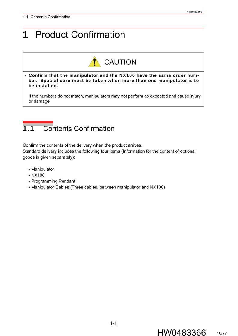
1.1 Contents Confirmation
Confirm the contents of the delivery when the product arrives.Standard delivery includes the following four items (Information for the content of optional goods is given separately):
• Manipulator• NX100• Programming Pendant• Manipulator Cables (Three cables, between manipulator and NX100)
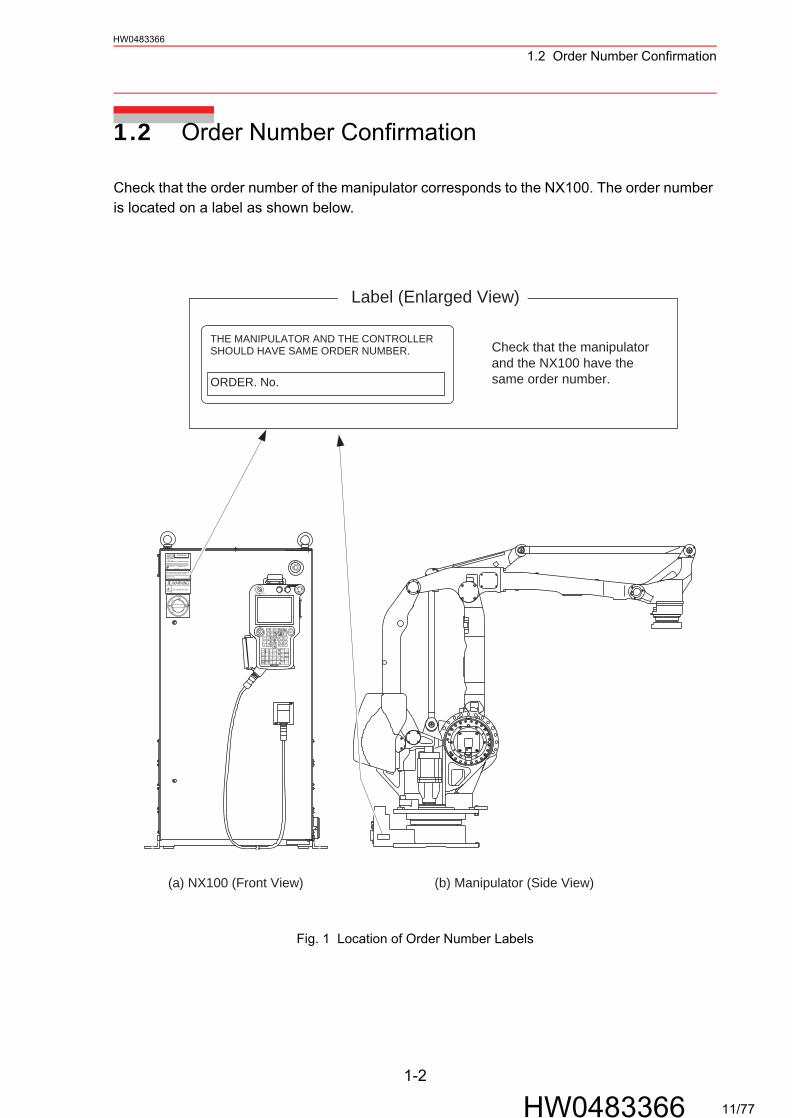
• Confirm that the manipulator and the NX100 have the same order num-ber. Special care must be taken when more than one manipulator is to be installed.
If the numbers do not match, manipulators may not perform as expected and cause injury or damage.
CAUTION
1-1
HW0483366 10/77
1.2 Order Number ConfirmationHW0483366
1.2 Order Number Confirmation
Check that the order number of the manipulator corresponds to the NX100. The order number is located on a label as shown below.
Fig. 1 Location of Order Number Labels
THE MANIPULATOR AND THE CONTROLLER SHOULD HAVE SAME ORDER NUMBER.
ORDER. No.
Label (Enlarged View)
N
PO
E
T
R G
YCM
S
E
E
SELECTSELECTSELECT
PLAYTEACHREMOTE
SERVOPOWER
S-X+S+
MAINMENU
R-x
R+x
ASSIST
COORD.MULTIDISPLAYSWITCH
X-
yy
64 5
AUXILIARY
AUXILIARY
TIMER1
WEAVINGCOMPLETE
VOLTAGE CURRENT2
WELDCOMPLETE
3RETRUCT
DELETE
BACK
INSERT
NEXT
L+L-
R-
LOCKINTER
WEAVINGSTART
7
+R+
B+B-
zT-
WELDSTART
8FEED9 TEST RUN SHIFT
zT+
EX-AXISSWITCH
ROBOT SWITCH
-
SHIFT
Y+Y-
0 ENTERCABCEK INTER. REF.POINT MODIFY
. -VOLTAGE CURRENT
SHORTCUTMENU
NX100200V 50Hz
kVA3PHASE220V 50/60Hz
NJ2484-1MADE IN JAPAN
DATE
SERIAL No.
ERCR-TYPE
POWER SUPPLY
******
ORDER NO.NJ1529
THE MANIPULATOR AND THE CONTROLLERSHOULD HAVE SAME ORDER NUMBER.
WARNINGDo not open the door
RESETO
FFTR
IPPED
ON
(a) NX100 (Front View) (b) Manipulator (Side View)
Check that the manipulatorand the NX100 have thesame order number.
1-2
HW0483366 11/77
2.1 Transporting MethodHW0483366
2 Transporting
2.1 Transporting Method
2.1.1 Using a Crane
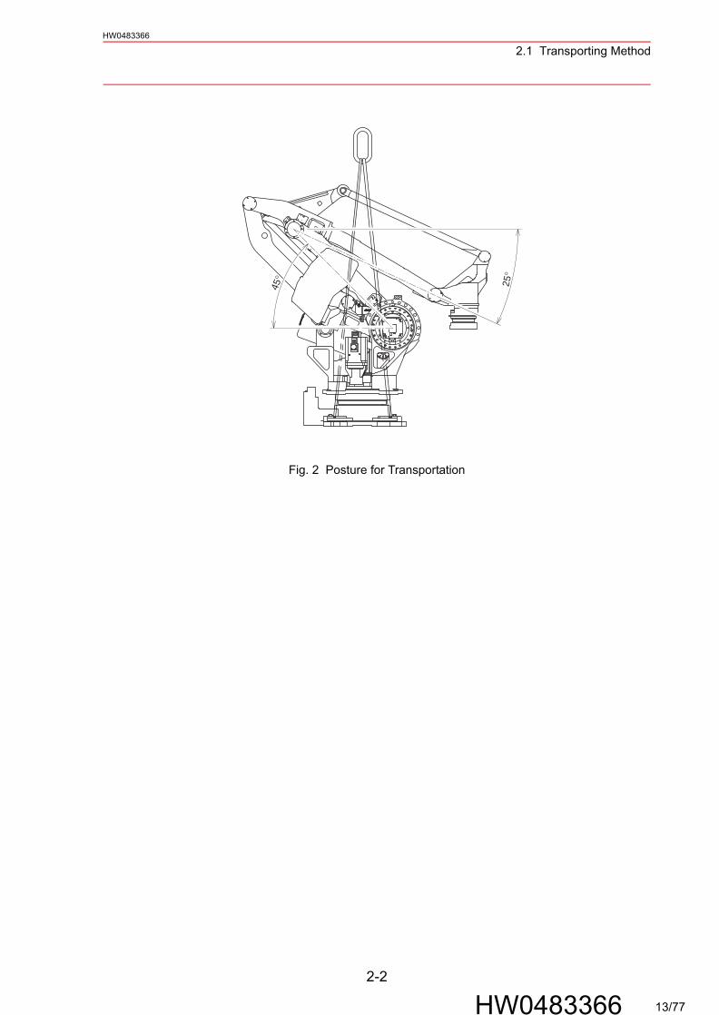
As a rule, when removing the manipulator from the package and moving it, a crane should be used. The manipulator should be lifted using wire rope threaded through shipping bolts and brackets. Be sure the manipulator is fixed with the shipping bolts and brackets before transporting, and lift it in the posture as shown in " Fig. 2 Posture for Transportation ".
• Sling applications and crane or forklift operations must be performed by authorized personnel only.
Failure to observe this caution may result in injury or damage.
• Avoid excessive vibration or shock during transporting.
Failure to observe this caution may adversely affect the performance as the system con-sists of precision components.
• The weight of the manipulator is approximately 2350 kg including the shipping bolts and brackets. Use a wire rope strong enough to withstand the weight.
• Be sure to mount the shipping bolts and brackets to transport the manipulator. The shipping bolts and brackets are designed to transport the manipulator: do not use them for anything other than transporting the manipulator.
• Avoid exerting force on the arm or motor unit when transporting, and use caution when using transporting equipment other than a crane or forklift, as injury may occur.
CAUTION
NOTE
2-1
HW0483366 12/77
2.1 Transporting MethodHW0483366
Fig. 2 Posture for Transportation
45° 25°
2-2
HW0483366 13/77
2.2 Shipping Bolts and BracketsHW0483366
2.2 Shipping Bolts and Brackets
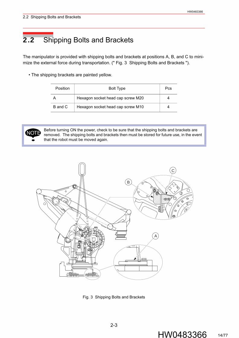
The manipulator is provided with shipping bolts and brackets at positions A, B, and C to mini-mize the external force during transportation. (" Fig. 3 Shipping Bolts and Brackets ").
• The shipping brackets are painted yellow.
Fig. 3 Shipping Bolts and Brackets
Position Bolt Type Pcs
A Hexagon socket head cap screw M20 4
B and C Hexagon socket head cap screw M10 4
Before turning ON the power, check to be sure that the shipping bolts and brackets are removed. The shipping bolts and brackets then must be stored for future use, in the event that the robot must be moved again.
NOTE
A
C
B
2-3
HW0483366 14/77
HW0483366
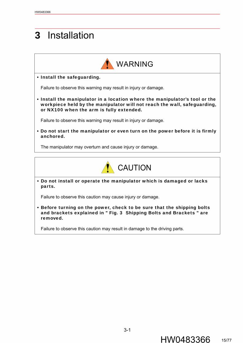
3 Installation
• Install the safeguarding.
Failure to observe this warning may result in injury or damage. • Install the manipulator in a location where the manipulator’s tool or the
workpiece held by the manipulator will not reach the wall, safeguarding, or NX100 when the arm is fully extended.
Failure to observe this warning may result in injury or damage.
• Do not start the manipulator or even turn on the power before it is firmly anchored.
The manipulator may overturn and cause injury or damage.
• Do not install or operate the manipulator which is damaged or lacks parts.
Failure to observe this caution may cause injury or damage.
• Before turning on the power, check to be sure that the shipping bolts and brackets explained in " Fig. 3 Shipping Bolts and Brackets " are removed.
Failure to observe this caution may result in damage to the driving parts.
WARNING
CAUTION
3-1
HW0483366 15/77

3.1 Installation of the SafeguardingHW0483366
3.1 Installation of the Safeguarding
To insure safety, be sure to install the safeguarding. They prevent unforeseen accidents with personnel and damage to equipment. The following is quoted for your information and guidance.
Responsibility for Safeguarding (ISO 10218)The user of a manipulator or robot system shall ensure that safeguarding is provided and used in accordance with Sections 6, 7, and 8 of this standard. The means and degree of safeguarding, including any redundancies, shall correspond directly to the type and level of hazard presented by the robot system consistent with the robot application. Safeguarding may include but not be limited to safeguarding devices, barriers, interlock barriers, perimeter guarding, awareness barriers, and awareness signals.
3.2 Mounting Procedures for Manipulator Base
The manipulator should be firmly mounted on a baseplate or a foundation strong enough to support the manipulator and withstand repulsion forces during acceleration and deceleration.Refer to " Table 1 Maximum Repulsion Forces of the Manipulator in an Emergency Stop " and " Table 2 Endurance Torque in Operation " to construct a solid foundation with the appropriate thickness to withstand maximum repulsion forces of the manipulator.A baseplate flatness must be kept at 0.5 mm or less: insufficient flatness of installation surface may deform the manipulator shape and affect its functional abilities. Mount the manipulator base as described in " 3.2.1 Mounting Example ".
Table 2 Endurance Torque in Operation
Table 1 Maximum Repulsion Forces of the Manipulator in an Emergency Stop
Maximum torque in horizontal rotation(S-axis moving direction)
39200 N·m(4000 kgf·m)
Maximum torque in vertical rotation (L-, U-axis moving direction)
88300 N·m(9000 kgf·m)
Endurance torque in horizontal operation(S-axis moving direction)
11800 N·m(1200 kgf·m)
Endurance torque in vertical operation(L-, U-axis moving direction)
26500 N·m(2700 kgf·m)
3-2
HW0483366 16/77

3.3 LocationHW0483366
3.2.1 Mounting Example
Fix the baseplate firmly to the floor. The baseplate should be durable enough to prevent shifting of the manipulator and mounting fixture. It is recommended to prepare a baseplate of 50 mm or more in thickness, and the anchor bolts of size M24 or more for the baseplate fixation. The anchor bolts should be inserted at least 200 mm deep into the floor.There are eight mounting holes on the manipulator base. Securely fix the manipulator to the baseplate with hexagon socke head cap screws M20 (80 mm long is recommended). Tighten the hexagon socket head cap screws and anchor bolts firmly so that they will not be loosened during the operation. See " Fig. 4 Mounting the Manipulator on Baseplate ".
Fig. 4 Mounting the Manipulator on Baseplate
3.3 Location
When the manipulator is installed, it is necessary to satisfy the undermentioned environmental conditions:
• Ambient temperature: 0° to 45°C • Humidity: 20 to 80%RH at constant temperature• Free from exposure to water, oil, or dust• Free from corrosive gas or liquid, or explosive gas • Free from excessive shock or vibration (less than 4.9 m/s2 [0.5 G])• Free from large electrical noise (plasma)• Flatness for installation is 0.5 mm or less
Hexagon socket head cap screw M20(8 screws) Spring washer
Manipulator base
Baseplate
Anchor bolt M24 or more
Flatness: 0.5 mm or less
Washer
50 mmor more
180 5401000
180
180
540
180
1000
Baseplate (reference)200 mm or more
Floor
28 dia. drilled hole(12 holes)
Units: mm
3-3
HW0483366 17/77
HW0483366
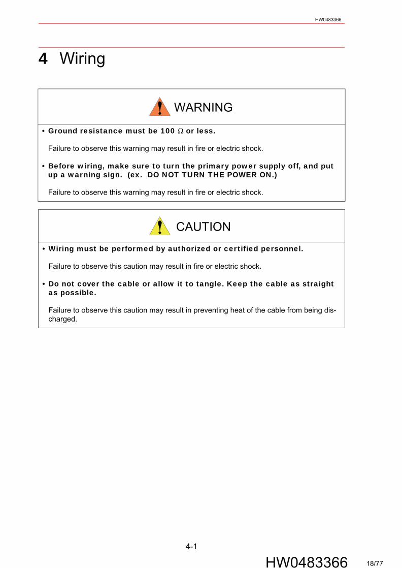
4 Wiring
• Ground resistance must be 100 Ω or less.
Failure to observe this warning may result in fire or electric shock.
• Before wiring, make sure to turn the primary power supply off, and put up a warning sign. (ex. DO NOT TURN THE POWER ON.)
Failure to observe this warning may result in fire or electric shock.
• Wiring must be performed by authorized or certified personnel.
Failure to observe this caution may result in fire or electric shock.
• Do not cover the cable or allow it to tangle. Keep the cable as straight as possible.
Failure to observe this caution may result in preventing heat of the cable from being dis-charged.
WARNING
CAUTION
4-1
HW0483366 18/77

4.1 GroundingHW0483366
4.1 Grounding
Follow the local regulations for grounding line size. A line of 5.5 mm2 or more is recommended.
Fig. 5 Grounding Method
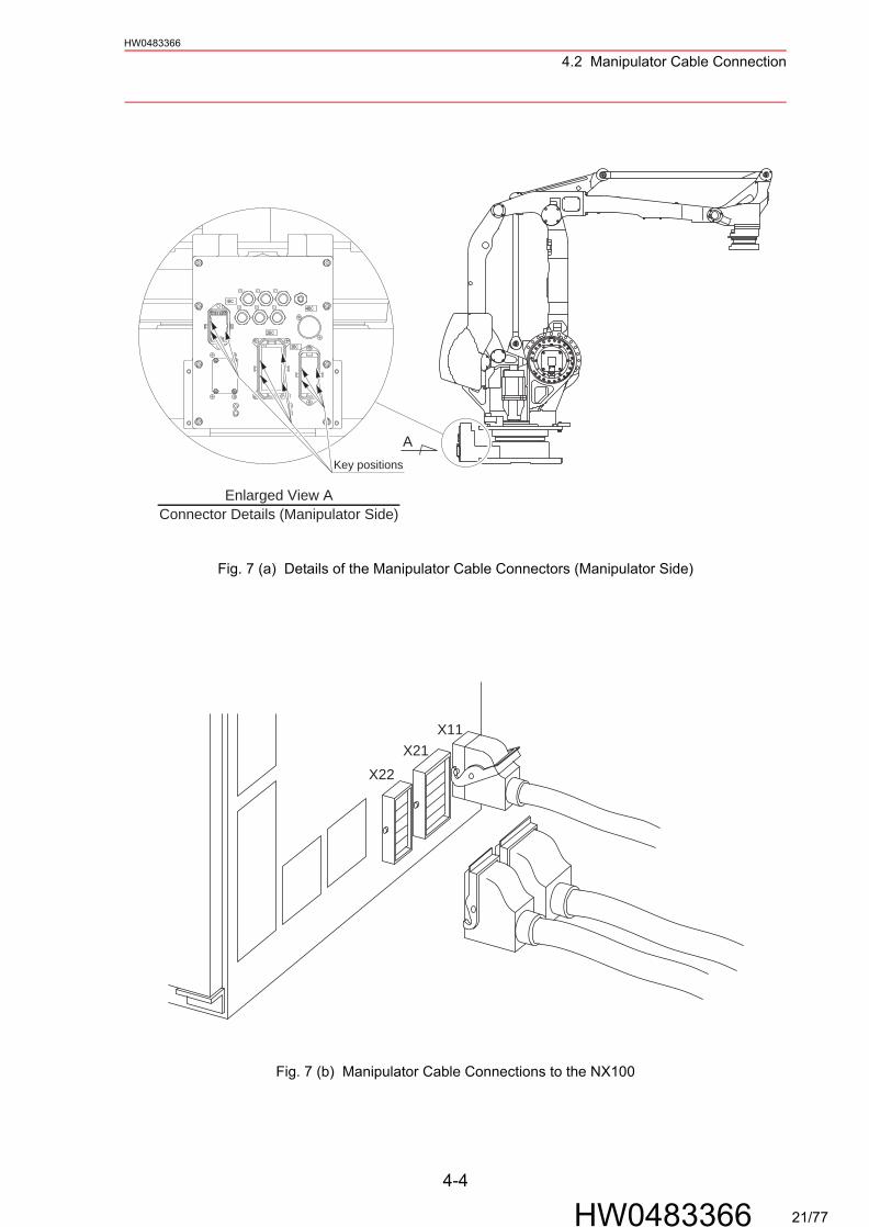
4.2 Manipulator Cable Connection
Three manipulator cables are provided: an encoder cable 1BC and two power cables 2BC and 3BC (refer to " Fig. 6 Manipulator Cable Connections "). Connect these cables to the connectors on the manipulator connector base and the NX100 by referring to " Fig. 7 (a) Details of the Manipulator Cable Connectors (Manipulator Side) " and " Fig. 7 (b) Manipulator Cable Connections to the NX100 ".
• Never use this line sharing with other ground lines or grounding electrodes for other elec-tric power, motor power, welding devices, etc.
• Where metal ducts, metallic conduits, or distributing racks are used for cable laying, grounding should be performed in accordance with Electric Equipment Technical Stan-dards.
Do not cover the cables with heat insulating material, and avoid multiple cabling.
NOTE
A
Bolt M8 (for grounding)Installed before shipment.
Enlarged View A5.5 mm2 or more
NOTE
4-2
HW0483366 19/77
4.2 Manipulator Cable ConnectionHW0483366
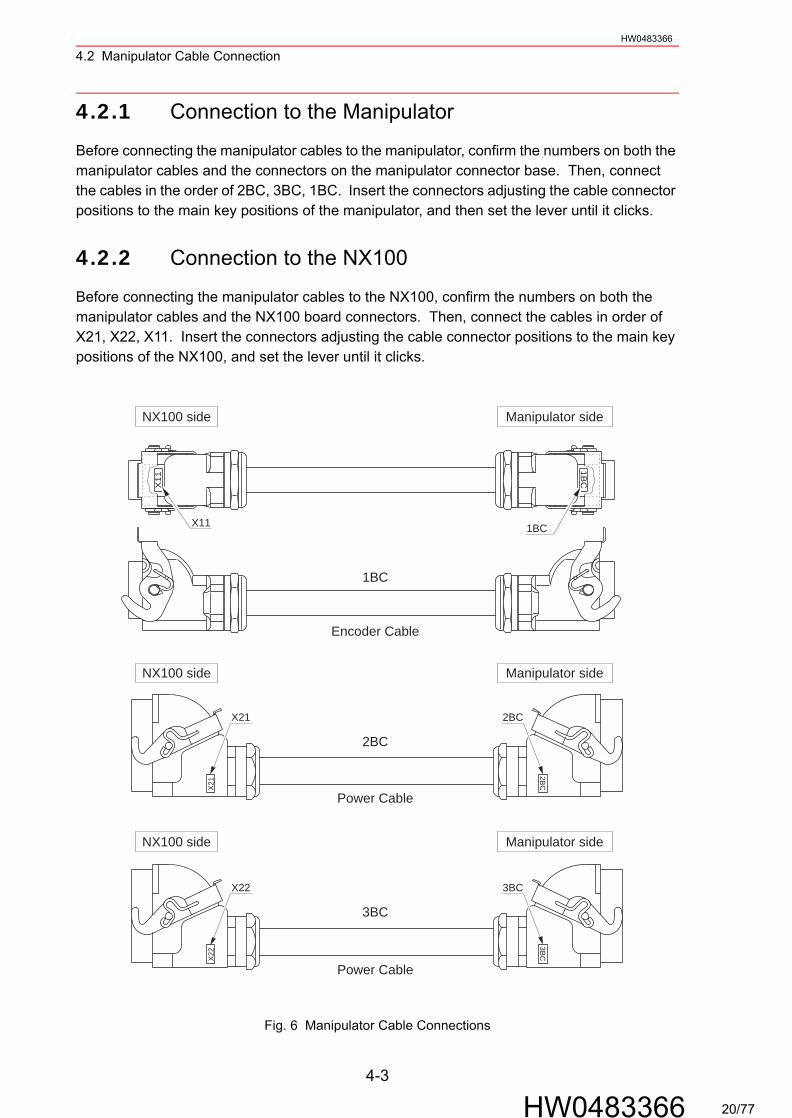
4.2.1 Connection to the Manipulator
Before connecting the manipulator cables to the manipulator, confirm the numbers on both the manipulator cables and the connectors on the manipulator connector base. Then, connect the cables in the order of 2BC, 3BC, 1BC. Insert the connectors adjusting the cable connector positions to the main key positions of the manipulator, and then set the lever until it clicks.
4.2.2 Connection to the NX100
Before connecting the manipulator cables to the NX100, confirm the numbers on both the manipulator cables and the NX100 board connectors. Then, connect the cables in order of X21, X22, X11. Insert the connectors adjusting the cable connector positions to the main key positions of the NX100, and set the lever until it clicks.
Fig. 6 Manipulator Cable Connections
2BCX21
1BC
2BC
3BC
3BCX22
3BC
X22
2BCX21
Power Cable
Power Cable
NX100 side
Encoder Cable
Manipulator side
X11
1BC
X11 1BC
NX100 side
NX100 side
Manipulator side
Manipulator side
4-3
HW0483366 20/77
4.2 Manipulator Cable ConnectionHW0483366
Fig. 7 (a) Details of the Manipulator Cable Connectors (Manipulator Side)
Fig. 7 (b) Manipulator Cable Connections to the NX100
Enlarged View AConnector Details (Manipulator Side)
Key positions
A
X22X21
X11
4-4
HW0483366 21/77
5.1 Basic Specifications
5 Basic Sp
5.1 Basic Sp
*1 SI units are used in*2 Conformed to ISO9*3 Refer to " 6.1 Allow
Item
Configuratio
Degree of Free
Payload
Repetitive Positioning
Range of Motion
S-axi
L-axis
U-axis
T-axis
Maximum Speed
S
L
U
T
Allowable Inertia (G
Mass
AmbientConditions
Tem
Hu
Vibration
O
Power Capac
HW0483366
ecifications
ecifications
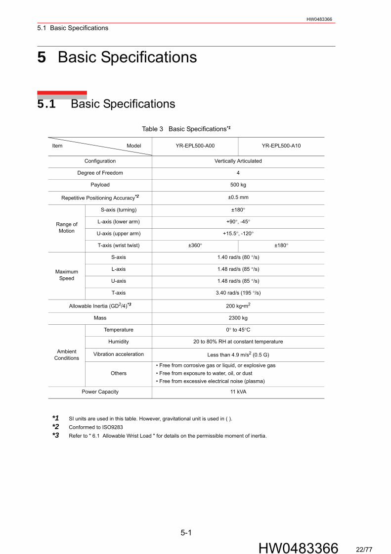
Table 3 Basic Specifications*1
Model YR-EPL500-A00 YR-EPL500-A10
n Vertically Articulated
dom 4
500 kg
Accuracy*2 ±0.5 mm
s (turning) ±180°
(lower arm) +90°, -45°
(upper arm) +15.5°, -120°
(wrist twist) ±360° ±180°
-axis 1.40 rad/s (80 °/s)
-axis 1.48 rad/s (85 °/s)
-axis 1.48 rad/s (85 °/s)
-axis 3.40 rad/s (195 °/s)
D2/4)*3 200 kg•m2
2300 kg
perature 0° to 45°C
midity 20 to 80% RH at constant temperature
acceleration Less than 4.9 m/s2 (0.5 G)
thers• Free from corrosive gas or liquid, or explosive gas• Free from exposure to water, oil, or dust• Free from excessive electrical noise (plasma)
ity 11 kVA
5-1
HW0483366
this table. However, gravitational unit is used in ( ).283able Wrist Load " for details on the permissible moment of inertia.
22/77
5.2 Part Names and Working AxesHW0483366
5.2 Part Names and Working Axes
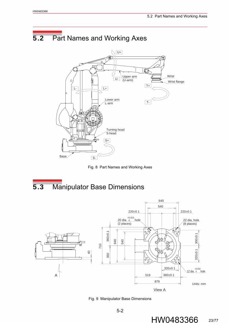
Fig. 8 Part Names and Working Axes
5.3 Manipulator Base Dimensions
Fig. 9 Manipulator Base Dimensions
T-
T+
U+
U-
S-
S+
L+L-
Lower armL-arm
Base
Upper arm(U-arm)
Wrist
Wrist flange
Turning headS-head
40
540220±0.1220±0.1
300±
0.1
320±
0.1
360±0.1
320±0.1
360±
0.1
540
A
+0.021 020 dia. hole
(2 places)
12 dia. hole+0.018 0
710
350
879
519
640
640
Units: mm
View A
22 dia. hole(8 places)
5-2
HW0483366 23/77
5.4 Dimensions and T-Point Maximum EnvelopeHW0483366
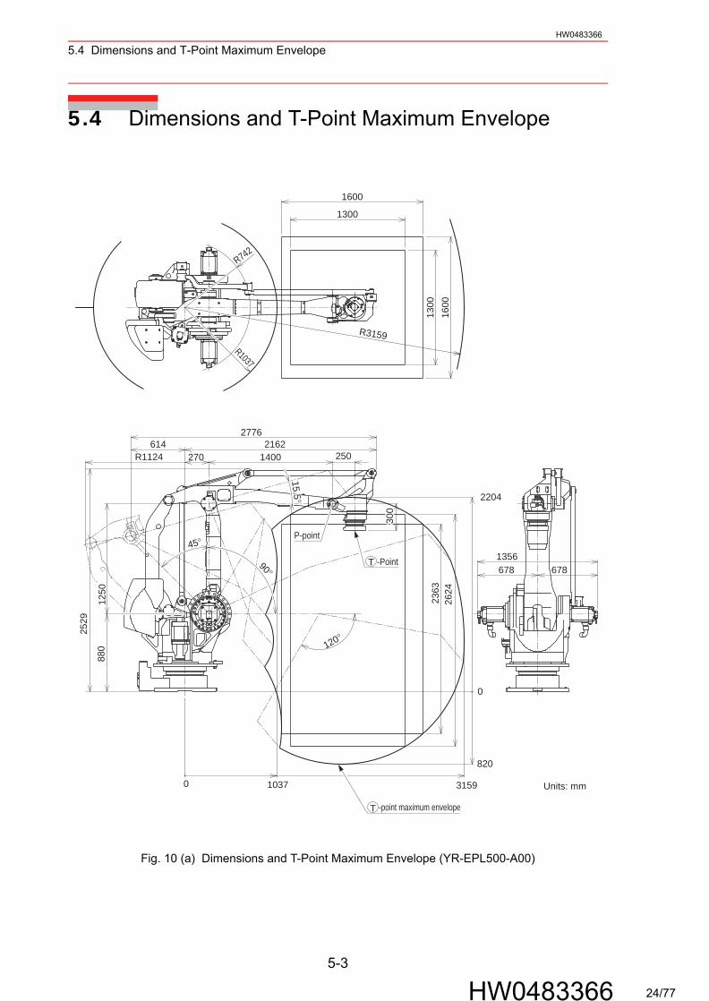
5.4 Dimensions and T-Point Maximum Envelope
Fig. 10 (a) Dimensions and T-Point Maximum Envelope (YR-EPL500-A00)
300
2776
0
0
120°
45°
90°
R1037
R742
820
2204
2624
2363
31591037
R11242162614
2501400270
2529
1250
880
6781356678
1600
1300
1600
1300
R3159
300
300
300
15.515.515.5°
Units: mm
T -Point
-point maximum envelopeT
P-point
5-3
HW0483366 24/77

5.4 Dimensions and T-Point Maximum EnvelopeHW0483366
Fig. 10 (b) Dimensions and T-point Maximum Envelope (YR-EPL500-A10)
R11242162614
2501400270
1600
R742
1300
R3159
R1037
1300
1600
2204
6781356
678
0
90°
120°
2363
2624
820
31591037
45°
1250
2529
880
0
2776
300
300
300
Units: mm
T -Point
-point maximum envelopeT
P-point
15.5°
5-4
HW0483366 25/77
5.5 Alterable Operating RangeHW0483366
5.5 Alterable Operating Range
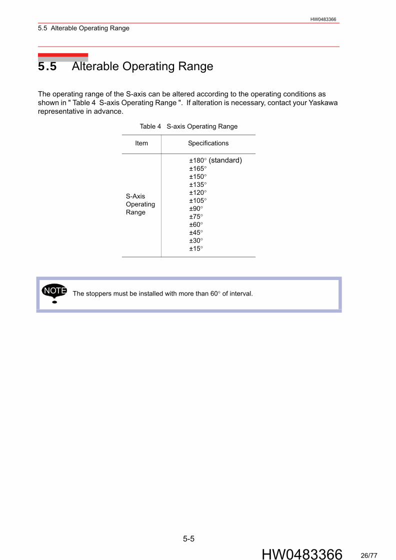
The operating range of the S-axis can be altered according to the operating conditions as shown in " Table 4 S-axis Operating Range ". If alteration is necessary, contact your Yaskawa representative in advance.
Table 4 S-axis Operating Range
Item Specifications
S-Axis OperatingRange
±180° (standard) ±165° ±150° ±135° ±120° ±105° ±90° ±75° ±60° ±45° ±30° ±15°
The stoppers must be installed with more than 60° of interval.NOTE
5-5
HW0483366 26/77
5.5 Alterable Operating RangeHW0483366
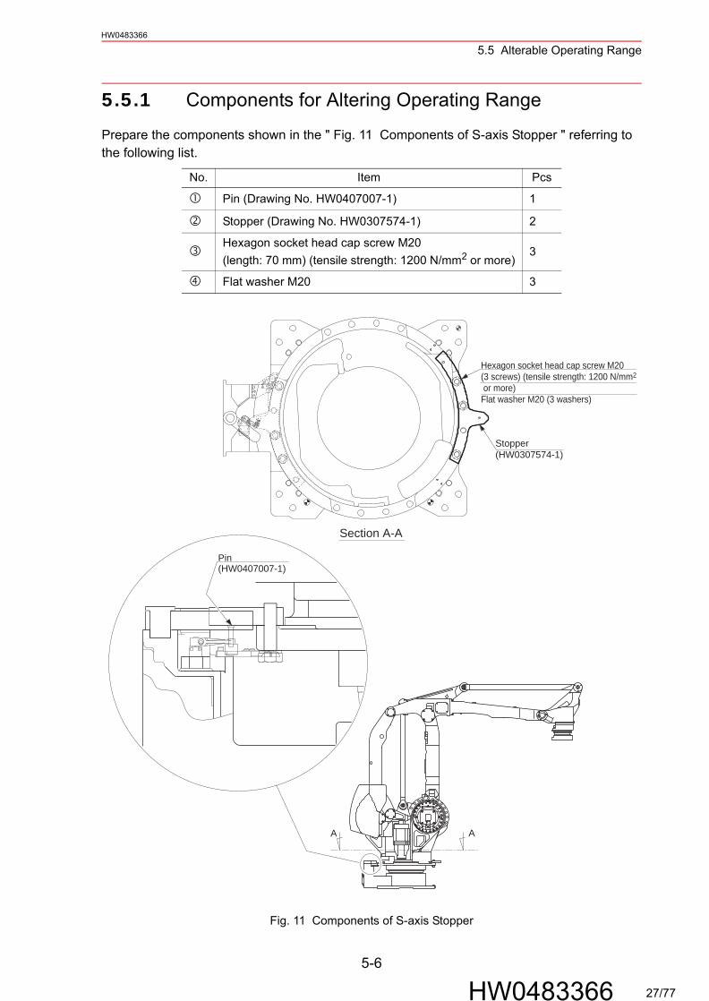
5.5.1 Components for Altering Operating Range
Prepare the components shown in the " Fig. 11 Components of S-axis Stopper " referring to the following list.
Fig. 11 Components of S-axis Stopper
No. Item Pcs
Pin (Drawing No. HW0407007-1) 1
Stopper (Drawing No. HW0307574-1) 2
Hexagon socket head cap screw M20(length: 70 mm) (tensile strength: 1200 N/mm2 or more)
3
Flat washer M20 3
AA
Stopper(HW0307574-1)
Pin(HW0407007-1)
Section A-A
Hexagon socket head cap screw M20(3 screws) (tensile strength: 1200 N/mm2
or more)Flat washer M20 (3 washers)
5-6
HW0483366 27/77
5.5 Alterable Operating RangeHW0483366
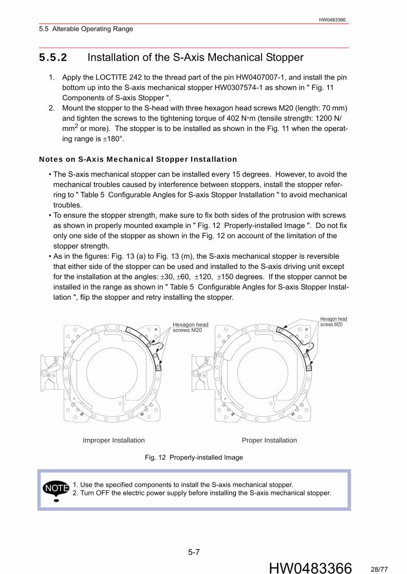
5.5.2 Installation of the S-Axis Mechanical Stopper
1. Apply the LOCTITE 242 to the thread part of the pin HW0407007-1, and install the pin bottom up into the S-axis mechanical stopper HW0307574-1 as shown in " Fig. 11 Components of S-axis Stopper ".
2. Mount the stopper to the S-head with three hexagon head screws M20 (length: 70 mm) and tighten the screws to the tightening torque of 402 N m (tensile strength: 1200 N/mm2 or more). The stopper is to be installed as shown in the Fig. 11 when the operat-ing range is ±180°.
Notes on S-Axis Mechanical Stopper Installation
• The S-axis mechanical stopper can be installed every 15 degrees. However, to avoid the mechanical troubles caused by interference between stoppers, install the stopper refer-ring to " Table 5 Configurable Angles for S-axis Stopper Installation " to avoid mechanical troubles.
• To ensure the stopper strength, make sure to fix both sides of the protrusion with screws as shown in properly mounted example in " Fig. 12 Properly-installed Image ". Do not fix only one side of the stopper as shown in the Fig. 12 on account of the limitation of the stopper strength.
• As in the figures: Fig. 13 (a) to Fig. 13 (m), the S-axis mechanical stopper is reversible that either side of the stopper can be used and installed to the S-axis driving unit except for the installation at the angles: ±30, ±60, ±120, ±150 degrees. If the stopper cannot be installed in the range as shown in " Table 5 Configurable Angles for S-axis Stopper Instal-lation ", flip the stopper and retry installing the stopper.
Fig. 12 Properly-installed Image
1. Use the specified components to install the S-axis mechanical stopper.2. Turn OFF the electric power supply before installing the S-axis mechanical stopper.
Improper Installation Proper Installation
Hexagon headscrews M20
Hexagon headscrews M20
NOTE
5-7
HW0483366 28/77
5.5 Alterable Operating RangeHW0483366
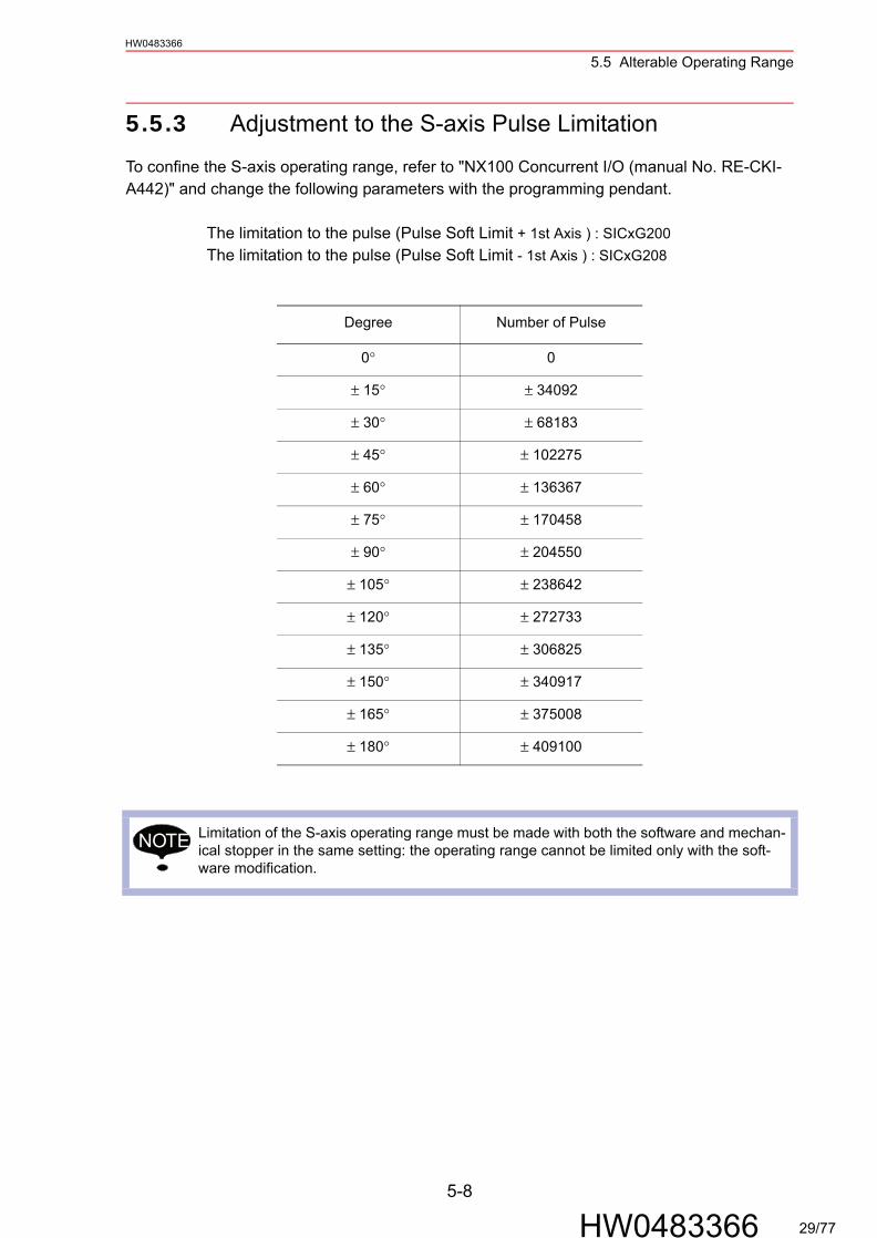
5.5.3 Adjustment to the S-axis Pulse Limitation
To confine the S-axis operating range, refer to "NX100 Concurrent I/O (manual No. RE-CKI-A442)" and change the following parameters with the programming pendant.
The limitation to the pulse (Pulse Soft Limit + 1st Axis ) : SICxG200 The limitation to the pulse (Pulse Soft Limit - 1st Axis ) : SICxG208
Degree Number of Pulse
0° 0
± 15° ± 34092
± 30° ± 68183
± 45° ± 102275
± 60° ± 136367
± 75° ± 170458
± 90° ± 204550
± 105° ± 238642
± 120° ± 272733
± 135° ± 306825
± 150° ± 340917
± 165° ± 375008
± 180° ± 409100
Limitation of the S-axis operating range must be made with both the software and mechan-ical stopper in the same setting: the operating range cannot be limited only with the soft-ware modification.
NOTE
5-8
HW0483366 29/77

5.5 Alterable Operating RangeHW0483366
180
165
150
135
120
105
9075
6045
3015
0-1
5-3
0-4
5-6
0-7
5-9
0-1
05-1
20-1
35-1
50-1
65-1
80-1
80-1
65-1
50-1
35-1
20-1
05 -90
-75
-60
-45
-30
-15 0 15 30 45 60 75 90 105
120
135
150
165
180
�C
onfig
urab
le a
ngle
�D
isab
led
angl
e
Pos
itive
(+)
Dire
ctio
n A
ngle
s
Negative (-) Direction Angles
Thi
s ta
ble
can
be u
sed
whe
n in
stal
ling
two
mec
hani
cal s
topp
ers
on th
e S
-axi
s.T
he v
ertic
al a
xis
of th
e ta
ble
show
s th
e an
gles
in th
e po
sitiv
e di
rect
ion,
and
the
horiz
onta
l axi
s of
the
tabl
e sh
ows
the
angl
es in
the
nega
tive
dire
ctio
n.F
or e
xam
ple,
if o
ne s
topp
er is
to b
e in
stal
led
at a
180
deg
ree
angl
e in
the
posi
tive
dire
ctio
n, th
e ot
her
one
can
be in
stal
led
with
in th
e ra
nge
of +
/-10
5 de
gree
ang
les:
sin
ce m
ore
than
60
degr
ees
of in
terv
al is
req
uire
d to
mou
nt tw
o st
oppe
rs, t
he c
hart
indi
cate
s th
at th
e ot
her
angl
es a
re in
appr
opria
te fo
r th
e in
stal
latio
n.
Exc
eptio
n: T
he to
p le
ft ce
ll (1
80°,
-18
0°)
indi
cate
s th
e m
ount
abili
ty o
f one
sto
pper
.
Tabl
e 5
Con
figur
able
Ang
les
for S
-axi
s St
oppe
r Ins
talla
tion
5-9
HW0483366 30/77
5.5 Alterable Operating RangeHW0483366
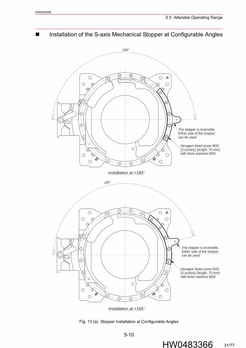
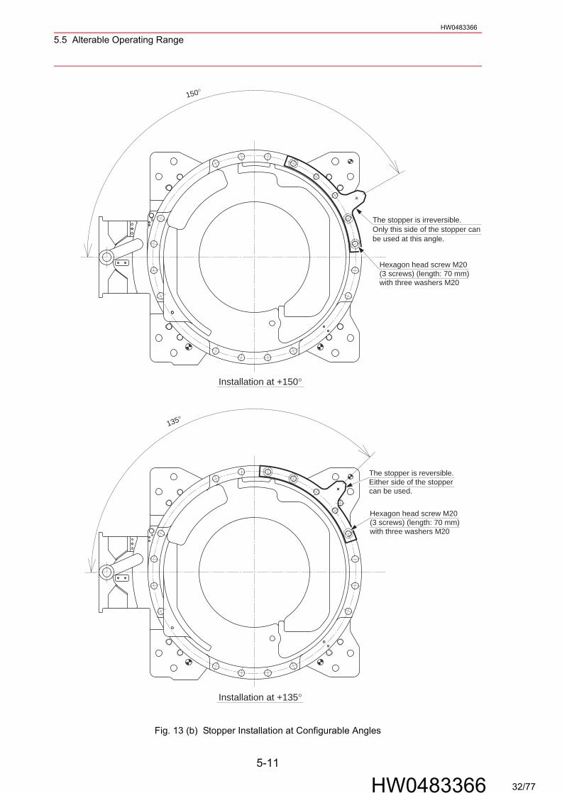
Installation of the S-axis Mechanical Stopper at Configurable Angles
Fig. 13 (a) Stopper Installation at Configurable Angles
165°
Installation at +165°
The stopper is reversible.Either side of the stoppercan be used.
Hexagon head screw M20(3 screws) (length: 70 mm)with three washers M20
The stopper is reversible.Either side of the stoppercan be used.
Hexagon head screw M20(3 screws) (length: 70 mm)with three washers M20
Installation at +180°
180°
5-10
HW0483366 31/77
5.5 Alterable Operating RangeHW0483366
Fig. 13 (b) Stopper Installation at Configurable Angles
135°
150°
Hexagon head screw M20(3 screws) (length: 70 mm)with three washers M20
Hexagon head screw M20(3 screws) (length: 70 mm)with three washers M20
The stopper is reversible.Either side of the stoppercan be used.
Installation at +150°
The stopper is irreversible.Only this side of the stopper canbe used at this angle.
Installation at +135°
5-11
HW0483366 32/77

5.5 Alterable Operating RangeHW0483366
Fig. 13 (c) Stopper Installation at Configurable Angles
105°
The stopper is reversible.Either side of the stoppercan be used.
Hexagon head screw M20(3 screws) (length: 70 mm)with three washers M20
Hexagon head screw M20(3 screws) (length: 70 mm)with three washers M20
The stopper is irreversible.Only this side of the stopper canbe used at this angle.
120°
Installation at +120°
Installation at +105°
5-12
HW0483366 33/77
5.5 Alterable Operating RangeHW0483366
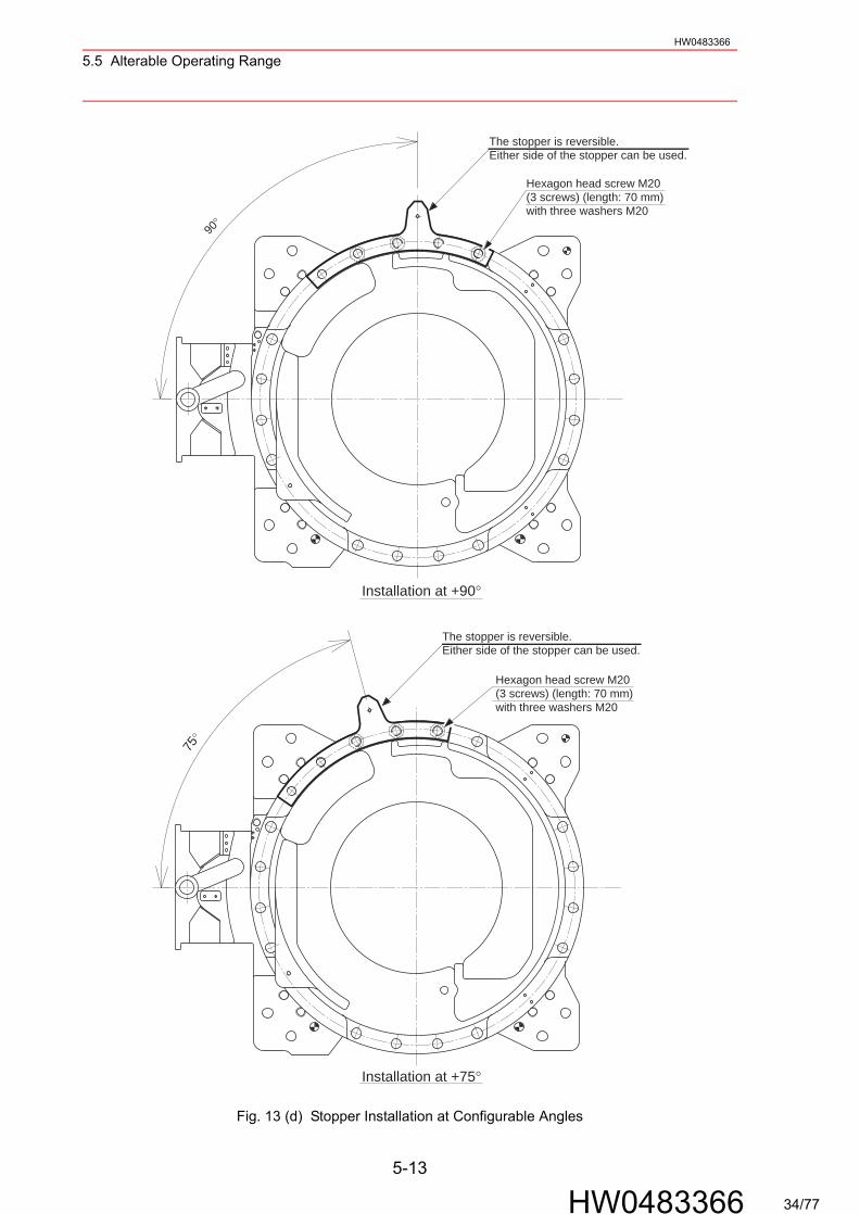
Fig. 13 (d) Stopper Installation at Configurable Angles
75°
90°
The stopper is reversible.Either side of the stopper can be used.
Installation at +90°
Hexagon head screw M20(3 screws) (length: 70 mm)with three washers M20
Installation at +75°
Hexagon head screw M20(3 screws) (length: 70 mm)with three washers M20
The stopper is reversible.Either side of the stopper can be used.
5-13
HW0483366 34/77
5.5 Alterable Operating RangeHW0483366
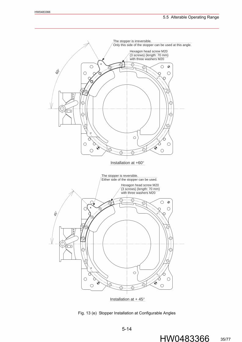
Fig. 13 (e) Stopper Installation at Configurable Angles
45°
60°
Installation at +60°
The stopper is reversible.Either side of the stopper can be used.
Hexagon head screw M20(3 screws) (length: 70 mm)with three washers M20
The stopper is irreversible.Only this side of the stopper can be used at this angle.
Hexagon head screw M20(3 screws) (length: 70 mm)with three washers M20
Installation at + 45°
5-14
HW0483366 35/77
5.5 Alterable Operating RangeHW0483366
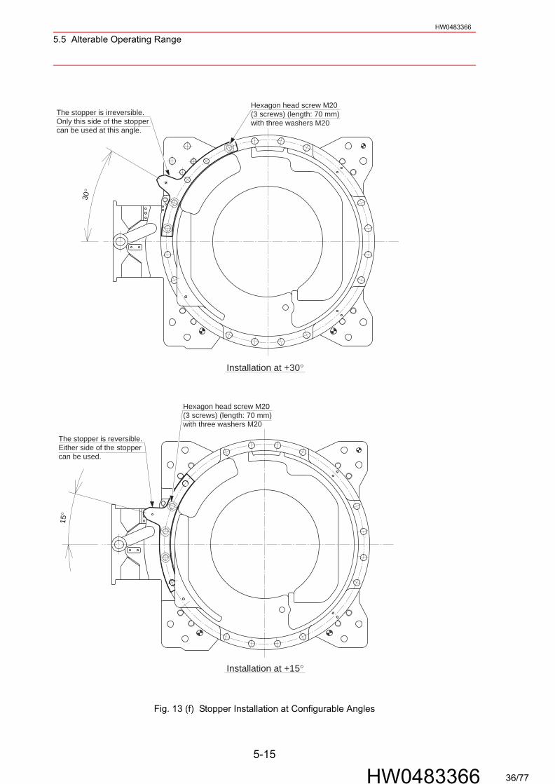
Fig. 13 (f) Stopper Installation at Configurable Angles
15°
30°
Installation at +30°
The stopper is reversible.Either side of the stoppercan be used.
Hexagon head screw M20(3 screws) (length: 70 mm)with three washers M20
The stopper is irreversible.Only this side of the stoppercan be used at this angle.
Hexagon head screw M20(3 screws) (length: 70 mm)with three washers M20
Installation at +15°
5-15
HW0483366 36/77
5.5 Alterable Operating RangeHW0483366
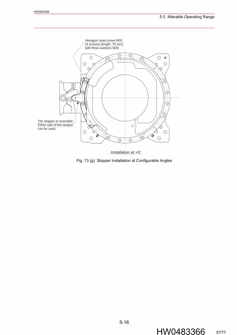
Fig. 13 (g) Stopper Installation at Configurable Angles
The stopper is reversible.Either side of the stoppercan be used.
Hexagon head screw M20(3 screws) (length: 70 mm)with three washers M20
Installation at +0°
5-16
HW0483366 37/77
5.5 Alterable Operating RangeHW0483366
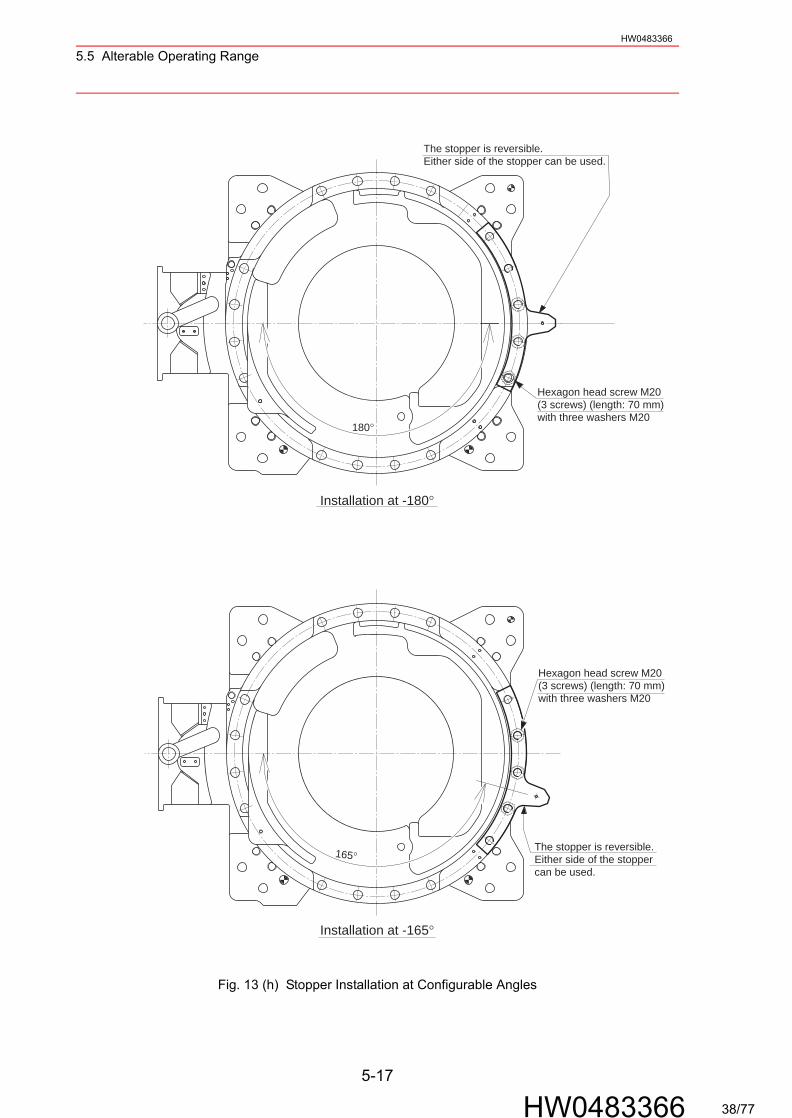
Fig. 13 (h) Stopper Installation at Configurable Angles
165°
180°
Installation at -180°
The stopper is reversible.Either side of the stoppercan be used.
Hexagon head screw M20(3 screws) (length: 70 mm)with three washers M20
Hexagon head screw M20(3 screws) (length: 70 mm)with three washers M20
Installation at -165°
The stopper is reversible.Either side of the stopper can be used.
5-17
HW0483366 38/77
5.5 Alterable Operating RangeHW0483366
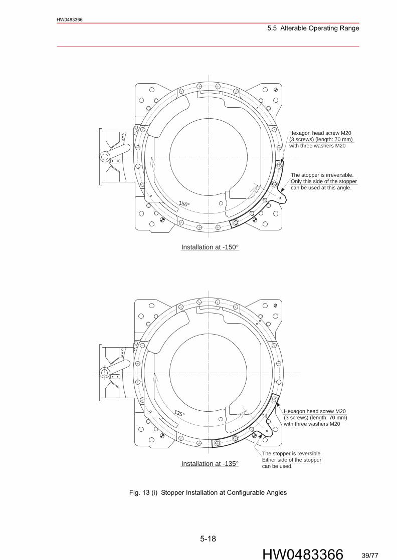
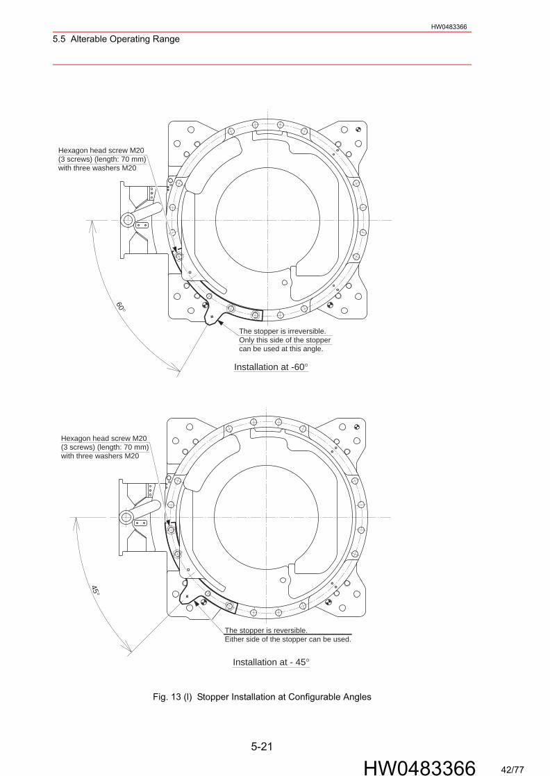
Fig. 13 (i) Stopper Installation at Configurable Angles
150°
135°
Installation at -150°
The stopper is reversible.Either side of the stoppercan be used.
Hexagon head screw M20(3 screws) (length: 70 mm)with three washers M20
The stopper is irreversible.Only this side of the stoppercan be used at this angle.
Hexagon head screw M20(3 screws) (length: 70 mm)with three washers M20
Installation at -135°
5-18
HW0483366 39/77

5.5 Alterable Operating RangeHW0483366
Fig. 13 (j) Stopper Installation at Configurable Angles
105°
120°
Installation at -120°
The stopper is reversible.Either side of the stoppercan be used.
Hexagon head screw M20(3 screws) (length: 70 mm)with three washers M20
The stopper is irreversible.Only this side of the stoppercan be used at this angle.
Hexagon head screw M20(3 screws) (length: 70 mm)with three washers M20 Installation at -105°
5-19
HW0483366 40/77
5.5 Alterable Operating RangeHW0483366
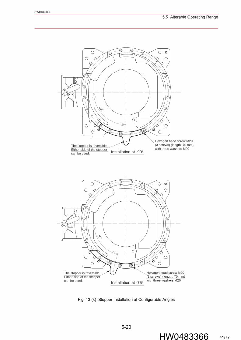
Fig. 13 (k) Stopper Installation at Configurable Angles
90°
75°
Installation at -90°The stopper is reversible.Either side of the stoppercan be used.
Hexagon head screw M20(3 screws) (length: 70 mm)with three washers M20
Hexagon head screw M20(3 screws) (length: 70 mm)with three washers M20Installation at -75°
The stopper is reversible.Either side of the stoppercan be used.
5-20
HW0483366 41/77
5.5 Alterable Operating RangeHW0483366
Fig. 13 (l) Stopper Installation at Configurable Angles
60°
45°
Installation at -60°
The stopper is reversible.Either side of the stopper can be used.
Hexagon head screw M20(3 screws) (length: 70 mm)with three washers M20
The stopper is irreversible.Only this side of the stoppercan be used at this angle.
Hexagon head screw M20(3 screws) (length: 70 mm)with three washers M20
Installation at - 45°
5-21
HW0483366 42/77

5.5 Alterable Operating RangeHW0483366
Fig. 13 (m) Stopper Installation at Configurable Angles
15°30°
The stopper is reversible.Either side of the stoppercan be used.
Hexagon head screw M20(3 screws) (length: 70 mm)with three washers M20
The stopper is irreversible.Only this side of the stoppercan be used at this angle.
Hexagon head screw M20(3 screws) (length: 70 mm)with three washers M20
Installation at -30°
Installation at -15°
5-22
HW0483366 43/77

6.1 Allowable Wrist LoadHW0483366
6 Allowable Load for Wrist Axis and Wrist Flange
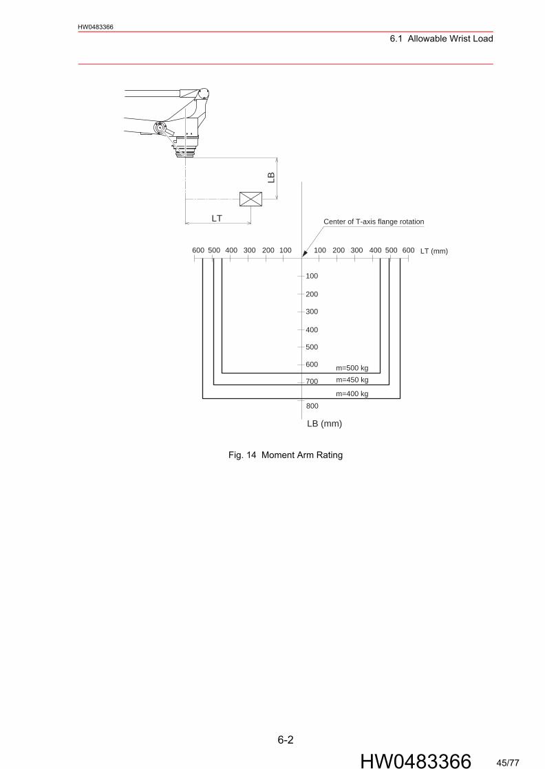
6.1 Allowable Wrist LoadThe allowable wrist load including the weight of the mount/gripper is 500 kg.The constraint conditions of the wrist axis are described below:
1. The total inertia (GD2/4) of T-axis is to be set at the value in the following table or less.
2. When the inertia of the volume load on the flange is small, the eccentricity of load cen-ter measured from T-axis flange rotation center is in the range shown in " Fig. 14 Moment Arm Rating ".When the inertia of the volume load on the flange is large, use the following formula to calculate the eccentricity LT.
Table 6 Allowable Total Inertia
Model Axis GD2/4 Inertia kg•m2
EPL500 T-axis 200
J=Ji+WL 2T
JJiWLT
: Total inertia (GD2/4) of the T-axis (kg m2): Inertia of the volume load on the flange (kg m2): Payload (kg): Eccentricity (mm)
Formula:
6-1
HW0483366 44/77
6.1 Allowable Wrist LoadHW0483366
Fig. 14 Moment Arm Rating
m=500 kgm=450 kg
m=400 kg
Center of T-axis flange rotation
600 500 400 300 200 100 100 200 300 400 500 600
100
200
300
400
500
600
700
800
LB (mm)
LB
LT (mm)
LT
6-2
HW0483366 45/77
6.2 Wrist FlangeHW0483366
6.2 Wrist Flange
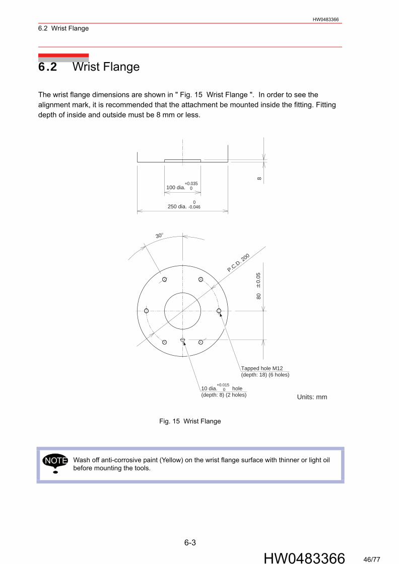
The wrist flange dimensions are shown in " Fig. 15 Wrist Flange ". In order to see the alignment mark, it is recommended that the attachment be mounted inside the fitting. Fitting depth of inside and outside must be 8 mm or less.
Fig. 15 Wrist Flange
Wash off anti-corrosive paint (Yellow) on the wrist flange surface with thinner or light oil before mounting the tools.
P.C.D. 2000.
0580
8
30°
Tapped hole M12(depth: 18) (6 holes)
10 dia. hole(depth: 8) (2 holes)
+0.015 0
Units: mm
100 dia.+0.035
0
0-0.046250 dia.
NOTE
6-3
HW0483366 46/77

7.1 Peripheral Equipment MountsHW0483366
7 System Application
7.1 Peripheral Equipment Mounts
Peripheral equipment mounts or tapped holes are provided to the wrist unit for easier installa-tion of the user’s system application as shown in " Fig. 16 Location of Peripheral Equipment Mounts/Tapped Holes ". When peripheral equipment is attached to the manipulator, the following conditions should be observed.
Fig. 16 Location of Peripheral Equipment Mounts/Tapped Holes
Table 7 Constraint for Attaching
Application Note
Cable Processing andValve Load
Up to 500 kg including the mass of the peripheral equipment attached to the wrist unit.
A
Tapped hole M8(depth: 15) (4 holes)
110
40
Enlarged View A
Units: mm
7-1
HW0483366 47/77
7.2 Internal User I/O Wiring Harness and Air LineHW0483366
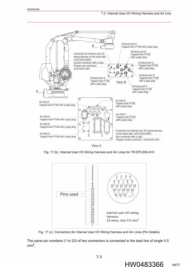
7.2 Internal User I/O Wiring Harness and Air Line
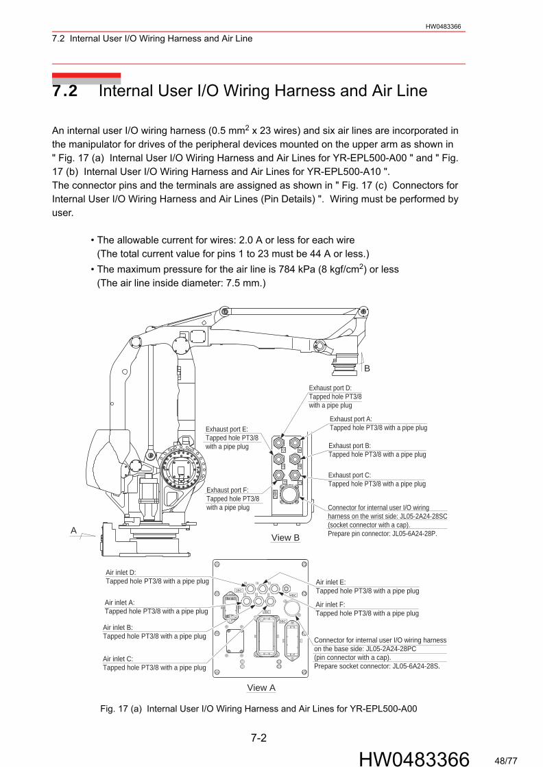
An internal user I/O wiring harness (0.5 mm2 x 23 wires) and six air lines are incorporated in the manipulator for drives of the peripheral devices mounted on the upper arm as shown in " Fig. 17 (a) Internal User I/O Wiring Harness and Air Lines for YR-EPL500-A00 " and " Fig. 17 (b) Internal User I/O Wiring Harness and Air Lines for YR-EPL500-A10 ".The connector pins and the terminals are assigned as shown in " Fig. 17 (c) Connectors for Internal User I/O Wiring Harness and Air Lines (Pin Details) ". Wiring must be performed by user.
• The allowable current for wires: 2.0 A or less for each wire(The total current value for pins 1 to 23 must be 44 A or less.)
• The maximum pressure for the air line is 784 kPa (8 kgf/cm2) or less(The air line inside diameter: 7.5 mm.)
Fig. 17 (a) Internal User I/O Wiring Harness and Air Lines for YR-EPL500-A00
A
B
D A
E B
F C
4BC
Exhaust port D:Tapped hole PT3/8 with a pipe plug
Exhaust port E:Tapped hole PT3/8 with a pipe plug
Exhaust port F:Tapped hole PT3/8 with a pipe plug
Exhaust port A:Tapped hole PT3/8 with a pipe plug
Exhaust port B:Tapped hole PT3/8 with a pipe plug
Exhaust port C:Tapped hole PT3/8 with a pipe plug
Connector for internal user I/O wiringharness on the wrist side: JL05-2A24-28SC (socket connector with a cap).Prepare pin connector: JL05-6A24-28P.View B
1BC
A
4BC
2BC
3BC
D FE
B CA
View A
Air inlet A:Tapped hole PT3/8 with a pipe plug
Air inlet B:Tapped hole PT3/8 with a pipe plug
Air inlet D:Tapped hole PT3/8 with a pipe plug
Air inlet C:Tapped hole PT3/8 with a pipe plug
Air inlet E:Tapped hole PT3/8 with a pipe plug
Air inlet F:Tapped hole PT3/8 with a pipe plug
Connector for internal user I/O wiring harness on the base side: JL05-2A24-28PC (pin connector with a cap).Prepare socket connector: JL05-6A24-28S.
7-2
HW0483366 48/77
7.2 Internal User I/O Wiring Harness and Air LineHW0483366
Fig. 17 (b) Internal User I/O Wiring Harness and Air Lines for YR-EPL500-A10
Fig. 17 (c) Connectors for Internal User I/O Wiring Harness and Air Lines (Pin Details)
The same pin numbers (1 to 23) of two connectors is connected in the lead line of single 0.5 mm2.
A
B Exhaust port A:Tapped hole PT3/8 with a pipe plug
Exhaust port B:Tapped hole PT3/8 with a pipe plug
Exhaust port C:Tapped hole PT3/8 with a pipe plug
Exhaust port D:Tapped hole PT3/8 with a pipe plug
Connector for internal user I/Owiring harness on the wrist side:JL05-2A24-28SC(socket connector with a cap).Prepare pin connector:JL05-6A24-28P.
View BExhaust port E:Tapped hole PT3/8 with a pipe plug
Exhaust port F:Tapped hole PT3/8 with a pipe plug
Air inlet D:Tapped hole PT3/8 with a pipe plug
Air inlet A:Tapped hole PT3/8 with a pipe plug
Air inlet B:Tapped hole PT3/8 with a pipe plug
Air inlet C:Tapped hole PT3/8 with a pipe plug
Air inlet E:Tapped hole PT3/8 with a pipe plug
Air inlet F:Tapped hole PT3/8 with a pipe plug
Connector for internal user I/O wiring harnesson the base side: JL05-2A24-28PC(pin connector with a cap).Prepare socket connector: JL05-6A24-28S.
1BC
A
4BC
2BC
3BC
D FE
B CA
View A
12
431 25
76
43
2116
2318 19 2017
22
141311 1210
1211
9 10
15
1716
1413
15
202122
19
23
18
85 7 8 96
Pins used
Internal user I/O wiringharness:23 wires, size 0.5 mm2
7-3
HW0483366 49/77
8.1 Locations of Limit SwitchesHW0483366
8 Electrical Equipment Specification
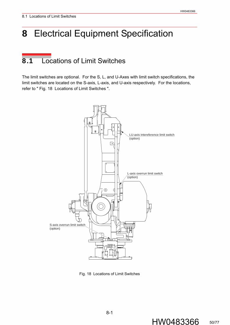
8.1 Locations of Limit Switches
The limit switches are optional. For the S, L, and U-Axes with limit switch specifications, the limit switches are located on the S-axis, L-axis, and U-axis respectively. For the locations, refer to " Fig. 18 Locations of Limit Switches ".
Fig. 18 Locations of Limit Switches
1BC
A
4BC
2BC
3BC
D FE
B CA
LU-axis intereference limit switch(option)
L-axis overrun limit switch(option)
S-axis overrun limit switch(option)
8-1
HW0483366 50/77
8.2 Internal ConnectionsHW0483366
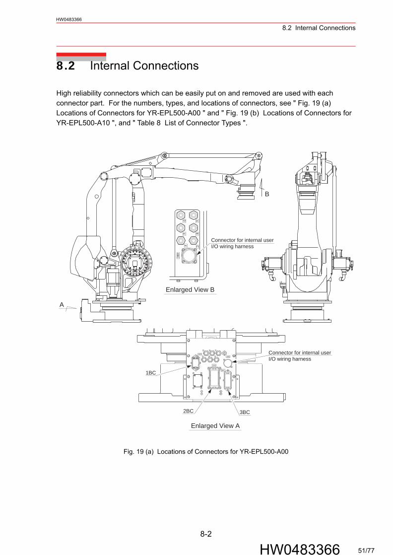
8.2 Internal Connections
High reliability connectors which can be easily put on and removed are used with each connector part. For the numbers, types, and locations of connectors, see " Fig. 19 (a) Locations of Connectors for YR-EPL500-A00 " and " Fig. 19 (b) Locations of Connectors for YR-EPL500-A10 ", and " Table 8 List of Connector Types ".
Fig. 19 (a) Locations of Connectors for YR-EPL500-A00
B
A
Connector for internal userI/O wiring harness
Enlarged View B
Connector for internal userI/O wiring harness
Enlarged View A
F C
E B
4BC
AD
1BC4BC
2BC
3BC
D FE
B CA
1BC
3BC2BC
8-2
HW0483366 51/77

8.2 Internal ConnectionsHW0483366
Fig. 19 (b) Locations of Connectors for YR-EPL500-A10
Table 8 List of Connector Types
Name Type of Connector
Connector Base Connector for internal user I/O wiring harness
JL05-2A24-28PC(JL05-6A24-28S: Optional)
Wrist Base Connector for internal user I/O wiring harness
JL05-2A24-28SC(JL05-6A24-28P: Optional)
A
B
B
DF
A
C
4BC
E
Connector for internal userI/O wiring harness
Connector for internal userI/O wiring harness
Enlarged View B
Enlarged View A
1BC4BC
2BC
3BC
D FE
B CA
2BC
1BC
3BC
8-3
HW0483366 52/77
8.2 Internal Connections
8-4
HW0483366
HW0483366
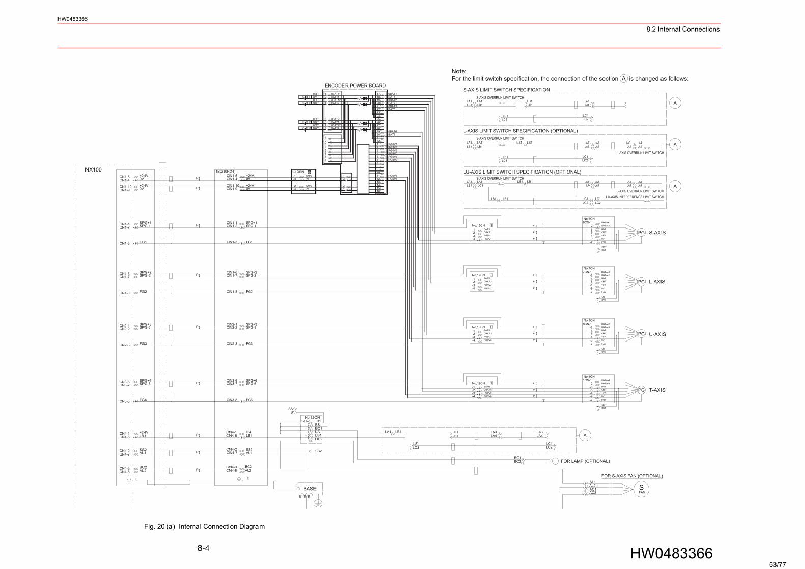
Fig. 20 (a) Internal Connection Diagram
BASE
LA4
AL1
P
P
CN4-7PCN4-7 AL1
FG6
SPG+6SPG-6P
CN3-6CN3-7
CN3-8FG6
SPG+6SPG-6CN3-6
CN3-7
CN3-8
FG3
SPG+3SPG-3P
CN2-1CN2-2
CN2-3FG3
SPG+3SPG-3CN2-1
CN2-2
CN2-3
SPG+2SPG-2P
CN1-6CN1-7
FG2CN1-8
SPG+2SPG-2CN1-6
CN1-7
FG2CN1-8
FG1CN1-3FG1CN1-3
SPG+1SPG-1CN1-2
CN1-1PSPG-1CN1-2
SPG+1CN1-1
PG T-AXISBAT
OBT
0V
BAT
+5V
FG6
OBT-6-2
1CN-1
-7-9-4-5
No.1CN
P
P
P
T-1
-4-3-2
No,19CNBAT6
PG5V6PG0V6
OBAT6
DATA+6DATA-6
U-AXISPGBAT-6
-28CN-1No.8CN
FG3
OBT
0V+5V
BAT
-7-9-4-5 OBT
P
P
P
U-1No,18CN
BAT3
-3-4
PG5V3PG0V3
OBAT3-2
DATA-3DATA+3
PG L-AXIS+5VOBTBAT
0V
-2
-4-5-6
-9
7CN-1No.7CN
P
P
PL-1
-4-3-2
PG0V2
BAT2
PG5V2OBAT2
No,17CN
OBTBAT
-7 FG2
DATA+2DATA-2
S-AXIS
DATA+1DATA-1-2
FG10V+5VOBT
OBTBAT
-4-5
-9-7
BAT-6PG
P
P
P
No.6CN6CN-1
S
OBAT1PG5V1PG0V1
BAT1-2-3-4
-1No,16CN
XNo.20CN1BC(10PX4)
-4-2
-3-1 +24V
0V
+24V0V
0V
0V
+24V
+24VCN1-9
CN1-5CN1-4
CN1-10P
P
CN1-10CN1-9 0V
+24V
+24V0VCN1-4
CN1-5 PG0V6PG5V6
9
1110
1615141312
1
42
3
PG0V2
PG0V3PG5V2
3
54
78
PG5V36
5
76
8
0BAT2BAT10BAT1
0BAT3BAT3
BAT2
1819
17
2122
2425
23
20
0BAT6BAT6
PG5V1PG0V1
2829
27
3031
2132
26
23
1
5
4
BAT110BAT12BAT12
0BAT21
0BAT11
87
1
432
BAT220BAT22BAT216
P BAT0BT
0BT
0BT
P BAT
K
K R
R
P0BTBATK R
PK R BAT
NX100
A
A
LA3LA4
LA4LA4
ALA3LA4
LA4
A
LA4LA3
LA4LA3
LA3
LC1LC2
LA4
LB1 LB1
LB1LB1
LA1LB1
LB1LA1
LB1LC3
LC2LC1
LA4LA3
LC1LC2
LA3LA4
LC2
LA4LA3
LC1LC2
BC1BC2
LB1 LB1
LB1
LA1LC3
LB1
LB1LC3
LB1LB1
LA3LA4
LC1
LC3
LB1
LB1
LA1
E
No.12CN
2
4
65-
-
3--
SS1B1
12CN-1- SS1
SS2
LA1
BC2LB1
BC1
B1
CN4-8CN4-3
E
CN4-1CN4-6
CN4-2
AL2BC2
+24LB1
SS2
E E E
LA1LB1
LB1LA1
LA1LB1
CN4-3CN4-8
CN4-2
CN4-6CN4-1
AL2BC2
E
+24V
SS2
LB1
FANS
AC2
AL2 AC1
AL1
S-AXIS LIMIT SWITCH SPECIFICATION
L-AXIS LIMIT SWITCH SPECIFICATION (OPTIONAL)
LU-AXIS LIMIT SWITCH SPECIFICATION (OPTIONAL)
S-AXIS OVERRUN LIMIT SWITCH
S-AXIS OVERRUN LIMIT SWITCH
S-AXIS OVERRUN LIMIT SWITCH
L-AXIS OVERRUN LIMIT SWITCH
L-AXIS OVERRUN LIMIT SWITCHLU-AXIS INTERFERENCE LIMIT SWITCH
Note:For the limit switch specification, the connection of the section A is changed as follows:
ENCODER POWER BOARD
FOR LAMP (OPTIONAL)
FOR S-AXIS FAN (OPTIONAL)
53/77
8.2 Internal Connections
8-5
HW0483366
HW0483366
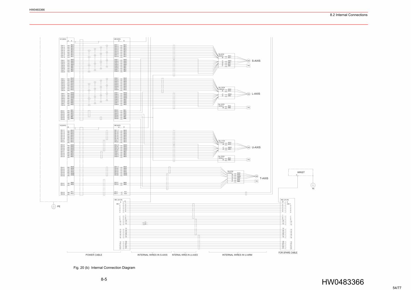
Fig. 20 (b) Internal Connection Diagram
WRIST
YB-E-F
-D-C
BA1BB1
ME1MW1
BA3BB3-B
No.15CN15CN-A
BB2BA2
-B14CN-ANo.14CN
PE
E
S-AXISSM
L-AXIS
YB
SM
9CN-ANo.9CN
-BMU1MV1
10CN-ANo.10CN
-B
-C-D
MV2
MW2ME2
MU2
U-AXIS
YB
SM
T-AXISSM
YB
MU6MV6
ME6
BB6BA6
MW6
11CN-ANo.11CN
-B
-D-C
MV3
ME3MW3
MU3
No.2CN2CN-A
-F
-B
-E-D-C
CN2-6CN2-5CN2-4CN2-3
CN1-6
CN1-8CN1-7
CN2-1CN2-2
CN1-4CN1-3
CN1-5
CN1-2CN1-1
2BC(8X5)
MW1
ME1ME1
MW1
MV1
MW1
MV1MV1
MW1
MU1MU1
MV1MU1
MU1
E
CN3-3
CN4-5
CN 6-2CN 6-1
CN4-7CN4-8
CN4-6
CN4-4
CN4-1CN4-2
CN3-8
CN4-3
CN3-7CN3-6
CN3-4CN3-5
CN3-2
CN2-8
CN3-1
MU2
BA2BA1
MW2
ME2ME2
ME2ME2
MW2
MV2
MW2MW2
MU2
MV2MV2
MV2
MU2
ME1
MU2
ME1CN2-7
CN3-2
CN3-4CN3-3
CN 1-4
CN 2-6CN3-1
CN 2- 1CN 2-2
CN 2- 3CN 2-4CN 2- 5
CN 1-5CN 1-6
CN 6-6
CN 1-3CN 1-2CN 1- 1
3BC(6X5)
CN 6-4CN 6-5
ME3
ME3ME3
BB6
ME3MW3
MV3MV3
MW3MW3MW3
MU3
MV3MU3
MV3
MU3MU3
E
BA6BB1
AC1AC2
CN5-3CN5-4
4BC (24-28)
CN 5-1CN 5-2
CN 4-4CN 4-5CN 4-6
CN 4- 1CN 4-2CN 4-3
MU6
ME6ME6
MU6MV6MV6MW6MW6
BA3CN 6-3
4BC-1
11
2019
1415
181716
12
13
910
34
87
65
21 E
-10
-19-20
-14-15-16-17-18
-12
-13
-11
-6
-9-8-7
-5-4-3-2
2322
-23
-21-22
21
1112
11
1920
14
161718
15
13
12
10
789
6
2
543
1
-10
-19-20
-14-15-16-17-18
-12
-13
-11
4BC-1
-6
-7-8-9
-2-3-4-5
E
2322
-23
-21-22
21
CN1-1
CN1-8
CN2-5CN2-4CN2-3CN2-2CN2-1
CN1-6CN1-7
CN1-5CN1-4CN1-3CN1-2
ME1ME1
MW1
MV1
MW1
MW1MW1
MV1
MU1
MV1
MU1MV1
MU1MU1
EX21(8X5)
CN4-6
CN4-8CN4-7
CN4-4CN4-5
CN4-3CN4-2CN4-1
CN3-4
CN3-8
CN3-5CN3-6CN3-7
CN3-2CN3-3
CN3-1
CN2-8CN2-7
MU2
ME2
BA1BA2
ME2ME2
ME2
MW2
MW2
MW2MW2
MV2MV2
MV2MV2
MU2
MU2MU2
ME1
CN 6-1CN 6-2
CN2-6 ME1
ME3ME3ME3
MU3
MW3ME3
MW3MW3MW3
MV3MV3
MV3MV3
MU3MU3
MU3
BB6BB1BA6
CN 6-5CN 6-6
CN 3-2CN 3-3CN 3-4
CN 2-5
CN 2-3
CN 3-1CN 2-6
CN 2-4
CN 1-4
CN 2-1CN 2-2
CN 1-6CN 1-5
CN 1-2CN 1-3
CN 1-1
X22(6X5)
CN 6-4
CN 5-4CN 5-3 AC2
AC1
ME6ME6
MW6MW6MV6
MU6
MV6MU6
CN 4-3
CN 5-1CN 5-2
CN 4-6CN 4-5CN 4-4
CN 4-1CN 4-2
CN 6-3 BA3
PE
4BC (24-28)
POWER CABLE INTERNAL WIRES IN S-AXIS INTERNAL WIRES IN LU-AXES INTERNAL WIRES IN U-ARMFOR SPARE CABLE
54/77
9.1 Inspection ScheduleHW0483366
9 Maintenance and Inspection
9.1 Inspection Schedule
Proper inspections are essential not only to assure that the mechanism will be able to function for a long period, but also to prevent malfunctions and assure safe operation. Inspection inter-vals are classified into six levels as shown in " Table 9 Inspection Items ". Conduct periodical inspections according to the inspection schedule in Table 9.In Table 9, the inspection items are categorized by three types of operations: operations which can be performed by personnel authorized by the user, operations which can be performed by personnel being trained, and operations which can be performed by service company person-nel. Only the specified personnel are to do the inspection work.
• Before maintenance or inspection, be sure to turn OFF the main power supply, and put up a warning sign. (ex. DO NOT TURN THE POWER ON.)
Failure to observe this warning may result in electric shock or injury.
• Maintenance and inspection must be performed by specified personnel.
Failure to observe this caution may result in electric shock or injury.
• For disassembly or repair, contact your Yaskawa representative.
• Do not remove the motor, and do not release the brake.
Failure to observe this caution may result in injury from unexpected turning of the manipu-lator’s arm.
• The battery pack must be connected before removing encoder connec-tor when maintenance and inspection.
Failure to observe this caution may result in the loss of home position data.
WARNING
CAUTION
9-1
HW0483366 55/77
9.1 Inspection ScheduleHW0483366
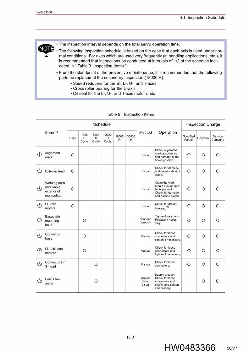
• The inspection interval depends on the total servo operation time.• The following inspection schedule is based on the case that each axis is used under nor-
mal conditions. For axes which are used very frequently (in handling applications, etc.), it is recommended that inspections be conducted at intervals of 1/2 of the schedule indi-cated in " Table 9 Inspection Items ".
• From the standpoint of the preventive maintenance, it is recommended that the following parts be replaced at the secondary inspection (18000 H).
• Speed reducers for the S-, L-, U-, and T-axes• Cross roller bearing for the U-axis• Oil seal for the L-, U-, and T-axis motor units
Table 9 Inspection Items
Items*4
Schedule
Method Operation
Inspection Charge
Daily1000
HCycle
5000H
Cycle
9000H
Cycle
18000H
36000H
Specified Person Licensee Service
Company
Alignment mark Visual
Check alignment mark accordance and damage at the home position.
External lead VisualCheck for damage and deterioration of leads.
Working area and whole exterior of manipulator
Visual
Clean the work area if dust or spat-ter is present. Check for damage and outside cracks.
LU-axis motors Visual
Check for grease leakage.*5
Baseplate mounting bolts
Spanner,Wrench
Tighten loose bolts. Replace if neces-sary.
Connector base Manual
Check for loose connectors and tighten if necessary.
LU-axis con-nectors Manual
Check for loose connectors and tighten if necessary.
Connectors in S-head Manual
Check for loose connectors.
L-axis bal-ancer
Grease Gun,Visual
Supply grease. Check for loose screw nuts and shafts, and tighten if necessary.
NOTE
9-2
HW0483366 56/77
9.1 Inspection ScheduleHW0483366
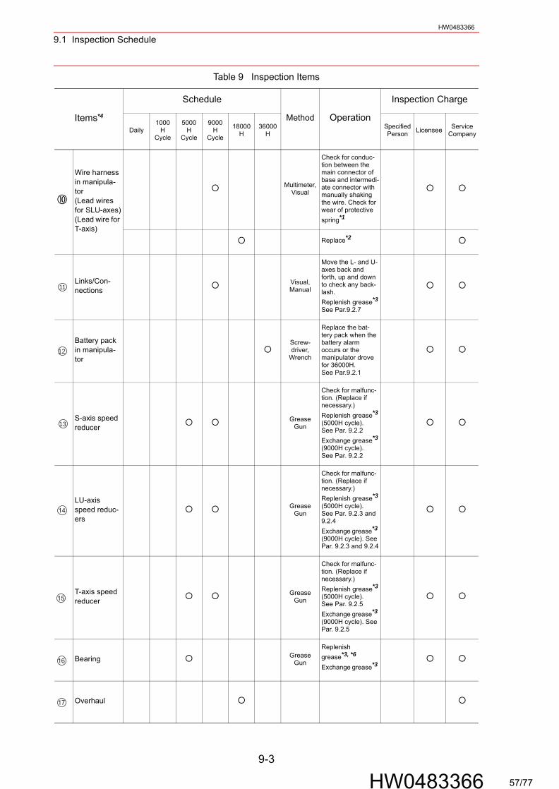
Wire harness in manipula-tor(Lead wires for SLU-axes)(Lead wire for T-axis)
Multimeter, Visual
Check for conduc-tion between the main connector of base and intermedi-ate connector with manually shaking the wire. Check for wear of protective spring*1
Replace*2
Links/Con-nections
Visual, Manual
Move the L- and U-axes back and forth, up and down to check any back-lash.Replenish grease*3See Par.9.2.7
Battery pack in manipula-tor
Screw-driver,
Wrench
Replace the bat-tery pack when the battery alarm occurs or the manipulator drove for 36000H.See Par.9.2.1
S-axis speed reducer
Grease Gun
Check for malfunc-tion. (Replace if necessary.)Replenish grease*3
(5000H cycle).See Par. 9.2.2Exchange grease*3(9000H cycle).See Par. 9.2.2
LU-axis speed reduc-ers
Grease Gun
Check for malfunc-tion. (Replace if necessary.)Replenish grease*3
(5000H cycle).See Par. 9.2.3 and 9.2.4Exchange grease*3 (9000H cycle). See Par. 9.2.3 and 9.2.4
T-axis speed reducer
Grease Gun
Check for malfunc-tion. (Replace if necessary.)Replenish grease*3
(5000H cycle).See Par. 9.2.5Exchange grease*3 (9000H cycle). See Par. 9.2.5
Bearing Grease Gun
Replenish grease*3, *6
Exchange grease*3
Overhaul
Table 9 Inspection Items
Items*4
Schedule
Method Operation
Inspection Charge
Daily1000
HCycle
5000H
Cycle
9000H
Cycle
18000H
36000H
Specified Person Licensee Service
Company
11
12
13
14
15
16
17
9-3
HW0483366 57/77
9.1 Inspection ScheduleHW0483366
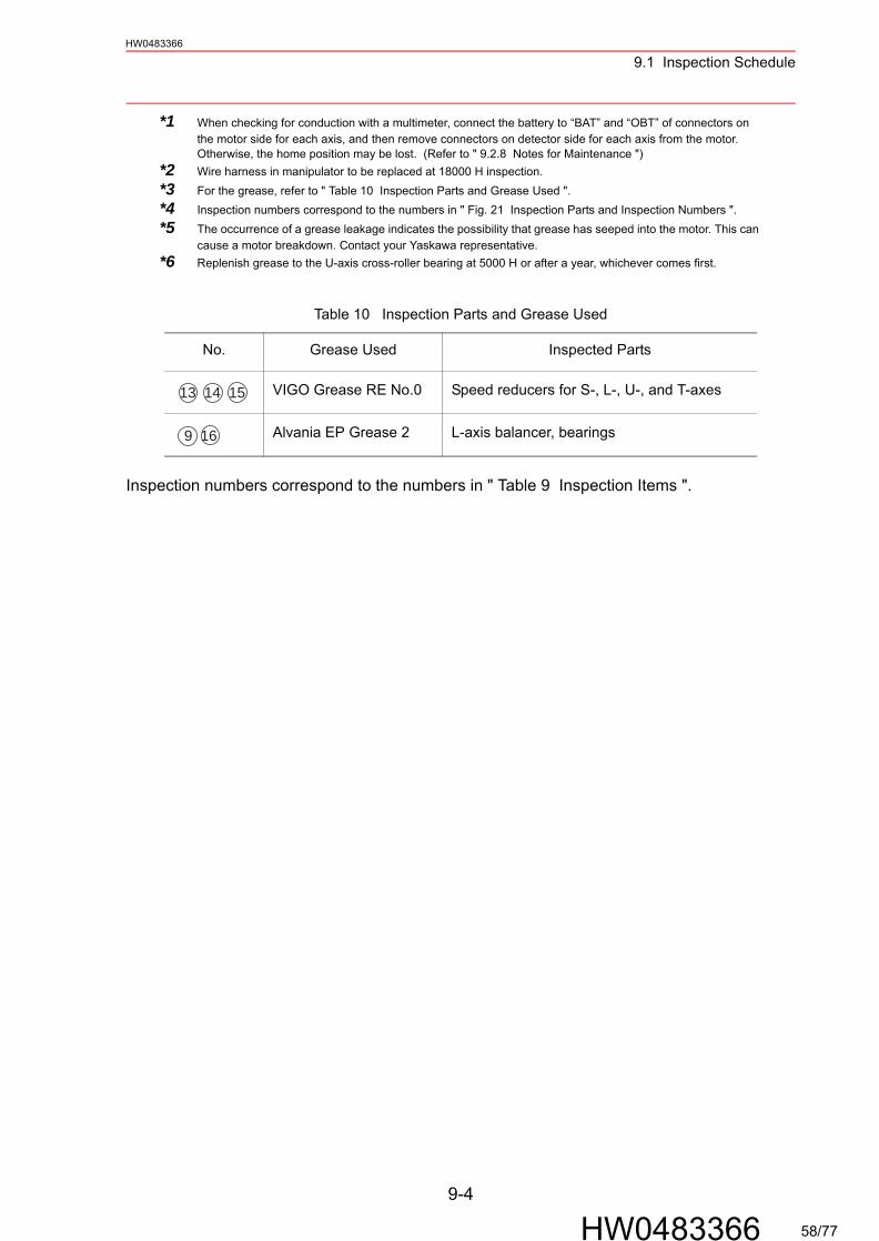
*1 When checking for conduction with a multimeter, connect the battery to “BAT” and “OBT” of connectors on the motor side for each axis, and then remove connectors on detector side for each axis from the motor. Otherwise, the home position may be lost. (Refer to " 9.2.8 Notes for Maintenance ")
*2 Wire harness in manipulator to be replaced at 18000 H inspection.*3 For the grease, refer to " Table 10 Inspection Parts and Grease Used ".*4 Inspection numbers correspond to the numbers in " Fig. 21 Inspection Parts and Inspection Numbers ".*5 The occurrence of a grease leakage indicates the possibility that grease has seeped into the motor. This can
cause a motor breakdown. Contact your Yaskawa representative.*6 Replenish grease to the U-axis cross-roller bearing at 5000 H or after a year, whichever comes first.
Inspection numbers correspond to the numbers in " Table 9 Inspection Items ".
Table 10 Inspection Parts and Grease Used
No. Grease Used Inspected Parts
VIGO Grease RE No.0 Speed reducers for S-, L-, U-, and T-axes
Alvania EP Grease 2 L-axis balancer, bearings
13 14 15
9 16
9-4
HW0483366 58/77
9.1 Inspection ScheduleHW0483366
1BC
A
4BC
2BC
3BC
L-ax
is1
DF
E BC
A
5
14
7
4
2
7
4
214
29
1T
-axi
s
1116
1116
U-a
xis
1
1116
1116
111611
16
1116
1611
28
A
13121
S-a
xis
6
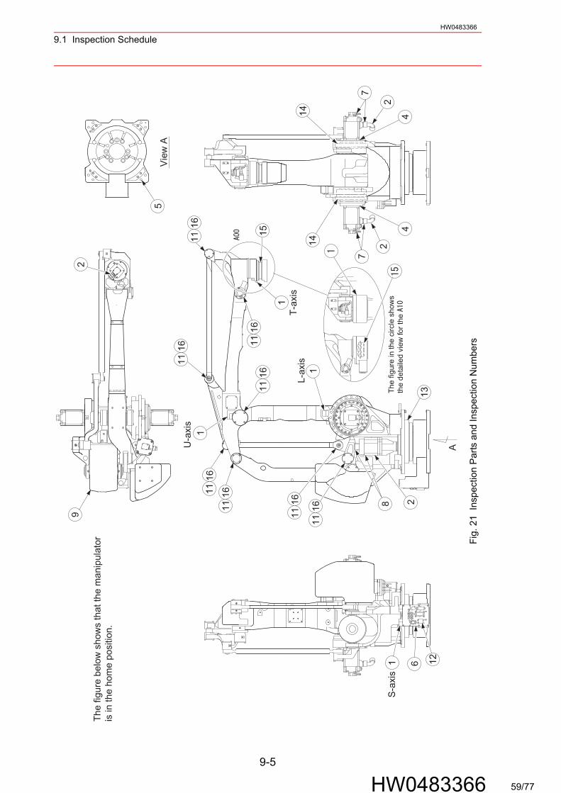
The
figu
re b
elow
sho
ws
that
the
man
ipul
ator
is in
the
hom
e po
sitio
n.
Vie
w A
15
The
figu
re in
the
circ
le s
how
s th
e de
taile
d vi
ew fo
r th
e
Fig.
21
Insp
ectio
n P
arts
and
Insp
ectio
n N
umbe
rs
9-5
HW0483366 59/77
9.2 Notes on Maintenance ProceduresHW0483366
9.2 Notes on Maintenance Procedures
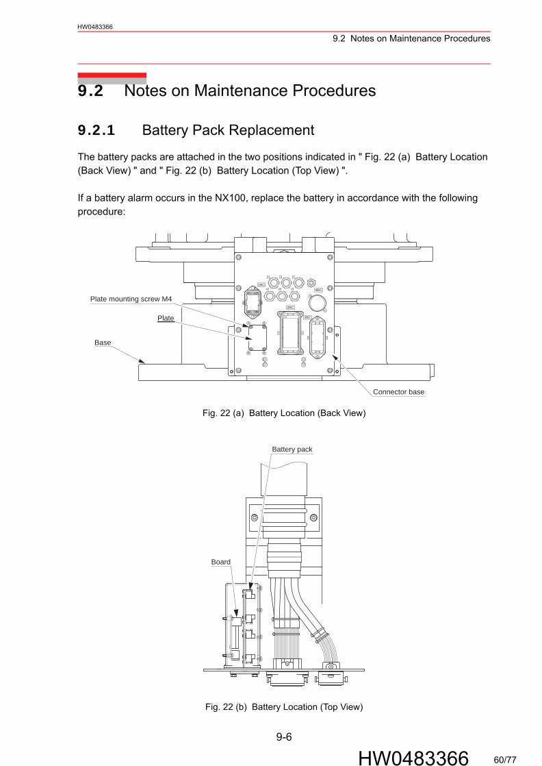
9.2.1 Battery Pack Replacement
The battery packs are attached in the two positions indicated in " Fig. 22 (a) Battery Location (Back View) " and " Fig. 22 (b) Battery Location (Top View) ".
If a battery alarm occurs in the NX100, replace the battery in accordance with the following procedure:
Fig. 22 (a) Battery Location (Back View)
Fig. 22 (b) Battery Location (Top View)
1BC
A
4BC
2BC
3BC
D FE
B CA
Base
Connector base
Plate mounting screw M4
Plate
Battery pack
Board
9-6
HW0483366 60/77
9.2 Notes on Maintenance ProceduresHW0483366
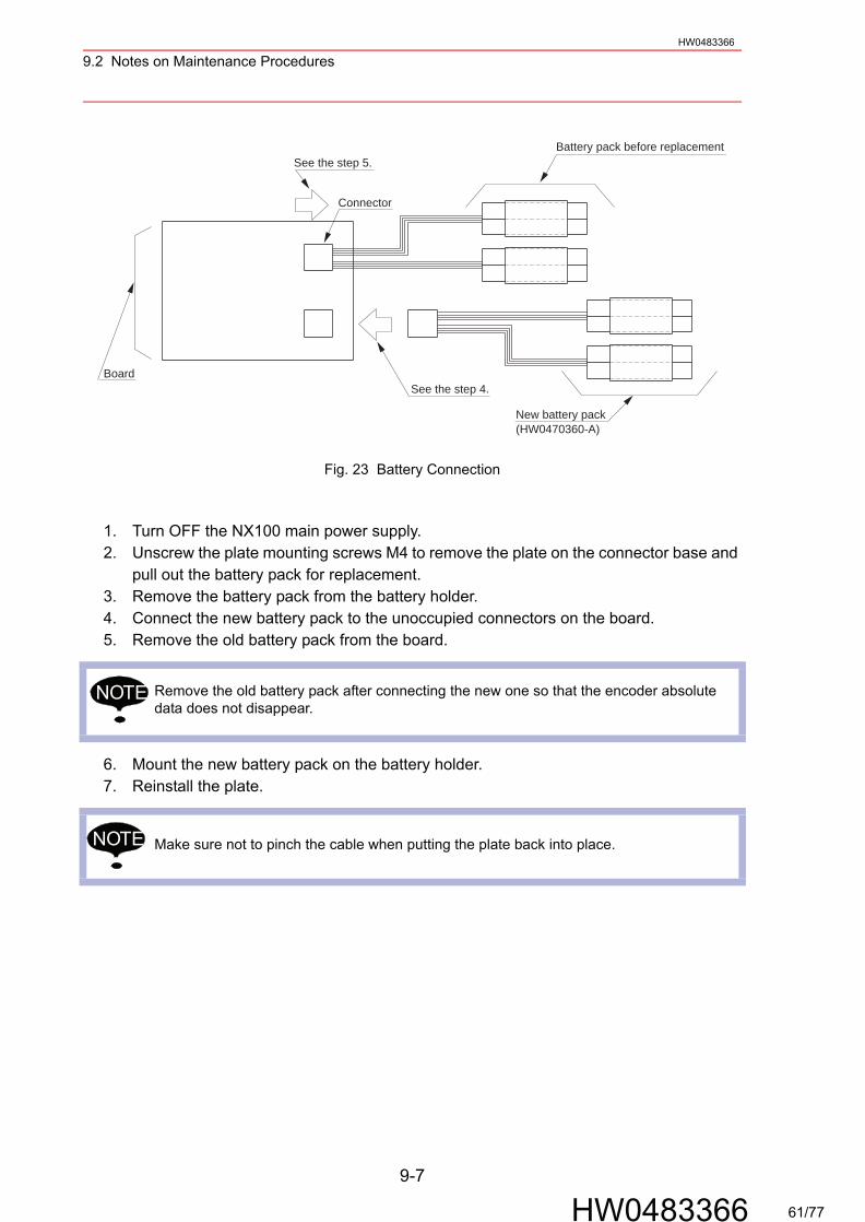
Fig. 23 Battery Connection
1. Turn OFF the NX100 main power supply.2. Unscrew the plate mounting screws M4 to remove the plate on the connector base and
pull out the battery pack for replacement.3. Remove the battery pack from the battery holder.4. Connect the new battery pack to the unoccupied connectors on the board.5. Remove the old battery pack from the board.
6. Mount the new battery pack on the battery holder.7. Reinstall the plate.
Remove the old battery pack after connecting the new one so that the encoder absolute data does not disappear.
Make sure not to pinch the cable when putting the plate back into place.
New battery pack(HW0470360-A)
Battery pack before replacementSee the step 5.
See the step 4.
Connector
Board
NOTE
NOTE
9-7
HW0483366 61/77

9.2 Notes on Maintenance ProceduresHW0483366
9.2.2 Grease Replenishment/Exchange for S-axis Speed Reducer and Gear
Fig. 24 S-axis Speed Reducer and Gear Diagram
Grease Replenishment (Refer to " Fig. 24 S-axis Speed Reducer and Gear Diagram ".)
1. Remove the hexagon socket head plug from the grease exhaust port.
2. Remove the hexagon socket head plug from the grease inlet and install the grease zerk A-PT1/4. Inject the grease into the grease inlet using a grease gun. (The grease zerk is delivered with the manipulator.)
3. Move the S-axis for a few minutes to discharge excess grease.4. Wipe the discharged grease with a cloth and reinstall the plug on the grease exhaust
port. Tighten the plug to a tightening torque of 24.5 N·m (2.5 kgf·m). (Apply Three Bond 1206C to the thread part of the plug.)
5. Remove the grease zerk from the grease inlet and reinstall the plug. Tighten the plug to a tightening torque of 4.9 N·m (0.5 kgf·m). (Apply Three Bond 1206C to the thread part of the plug.)
If grease is added with the plug on, the grease will go inside the motor and may cause a damage. Never fail to remove the plug before the grease injection.
Grease type: VIGO Grease RE No.0Amount of grease: Approx. 2100 cc
(4200 cc for the 1st supply)
1BC
2BC
3BC
D FE
B CA 4BC
Grease exhaust port(Hexagon socket head plug)
S-axis speed reducer
Grease inlet(Hexagon socket head plug)
NOTE
9-8
HW0483366 62/77
9.2 Notes on Maintenance ProceduresHW0483366
Grease Exchange (Refer to " Fig. 24 S-axis Speed Reducer and Gear Diagram ".)
1. Remove the hexagon socket head plug from the grease exhaust port.
2. Remove the hexagon socket head plug from the grease inlet and install the grease zerk A-PT1/4. Inject the grease into the grease inlet using a grease gun. (The grease zerk is delivered with the manipulator.)
3. The grease exchange is complete when new grease appears in the grease exhaust port. The new grease can be distinguished from the old grease by color.
4. Move the S-axis for a few minutes to discharge excess grease.5. Wipe the discharged grease with a cloth and reinstall the plug on the grease exhaust
port. Tighten the plug to a tightening torque of 24.5 N·m (2.5 kgf·m). (Apply Three Bond 1206C to the thread part of the plug.)
6. Remove the grease zerk from the grease inlet and reinstall the plug. Tighten the plug to a tightening torque of 4.9 N·m (0.5 kgf·m). (Apply Three Bond 1206C to the thread part of the plug.)
If grease is added with the plug on, the grease will go inside the motor and may cause a damage. Never fail to remove the plug before the grease injection.
Grease type: VIGO Grease RE No.0Amount of grease: Approx. 10400 cc
If the plug is installed while the grease is being exhausted, the grease will go inside the motor and may cause a damage. Make sure to install the plug when the grease exhaust is complete.
NOTE
NOTE
9-9
HW0483366 63/77

9.2 Notes on Maintenance ProceduresHW0483366
9.2.3 Grease Replenishment/Exchange for L-axis Speed Reducer
Fig. 25 L-axis Speed Reducer Diagram
Grease Replenishment (Refer to " Fig. 25 L-axis Speed Reducer Diagram ".)
1. Remove the hexagon socket head plug from the grease exhaust port.
2. Remove the hexagon socket head plug from the grease inlet and install the grease zerk A-PT1/8. Inject the grease into the grease inlet using a grease gun. (The grease zerk is delivered with the manipulator.)
3. Move the L-axis for a few minutes to discharge excess grease. 4. Wipe the discharged grease with a cloth and reinstall the plug on the grease exhaust
port. Tighten the plug to a tightening torque of 24.5 N·m (2.5 kgf·m) for the plug PT3/8. (Apply Three Bond 1206C to the thread part of the plug.)
5. Remove the grease zerk from the grease inlet and reinstall the plug. Tighten the plug to a tightening torque of 4.9 N·m (0.5 kgf·m). (Apply Three Bond 1206C to the thread part of the plug.)
If grease is added with the plug on, the grease will go inside the motor and may cause a damage. Never fail to remove the plug before the grease injection.
Grease type: VIGO Grease RE No.0Amount of grease: Approx. 460 cc
(920 cc for the 1st supply)
Grease exhaust port(Hexagon socket head plug)L-axis speed reducer
Grease inlet(Hexagon socket head plug)
NOTE
9-10
HW0483366 64/77

9.2 Notes on Maintenance ProceduresHW0483366
• If the L-arm is tilted over 80 degrees, the link-C interferes with the plug for air exhaust.
Do not tilt the L-arm over 80 degrees when verifying the manipulator operation.
CAUTION
80°90°
170° Link-C
Plug for air exhaust
Link-C
Plug for air exhaust
Link-C
9-11
HW0483366 65/77
9.2 Notes on Maintenance ProceduresHW0483366
Grease Exchange (Refer to " Fig. 25 L-axis Speed Reducer Dia-gram ".)
1. Remove the hexagon socket head plug from the grease exhaust port.
2. Remove the hexagon socket head plug from the grease inlet and install the grease zerk A-PT1/8. Inject the grease into the grease inlet using a grease gun. (The grease zerk is delivered with the manipulator.)
3. The grease exchange is complete when new grease appears in the grease exhaust port. The new grease can be distinguished from the old grease by color.
4. Move the L-axis for a few minutes to discharge excess grease.5. Wipe the discharged grease with a cloth and reinstall the plug on the grease exhaust
port. Tighten the plug to a tightening torque of 24.5 N·m (2.5 kgf·m). (Apply Three Bond 1206C to the thread part of the plug.
6. Remove the grease zerk from the grease inlet and reinstall the plug. Tighten the plug to a tightening torque of 4.9 N·m (0.5 kgf·m). (Apply Three Bond 1206C to the thread part of the plug.)
If grease is added with the plug on, the grease will go inside the motor and may cause a damage. Never fail to remove the plug before the grease injection.
Grease type: VIGO Grease RE No.0Amount of grease: Approx. 2300 cc
If the plug is installed while the grease is being exhausted, the grease will go inside the motor and may cause a damage. Make sure to install the plug when the grease exhaust is complete.
NOTE
NOTE
9-12
HW0483366 66/77
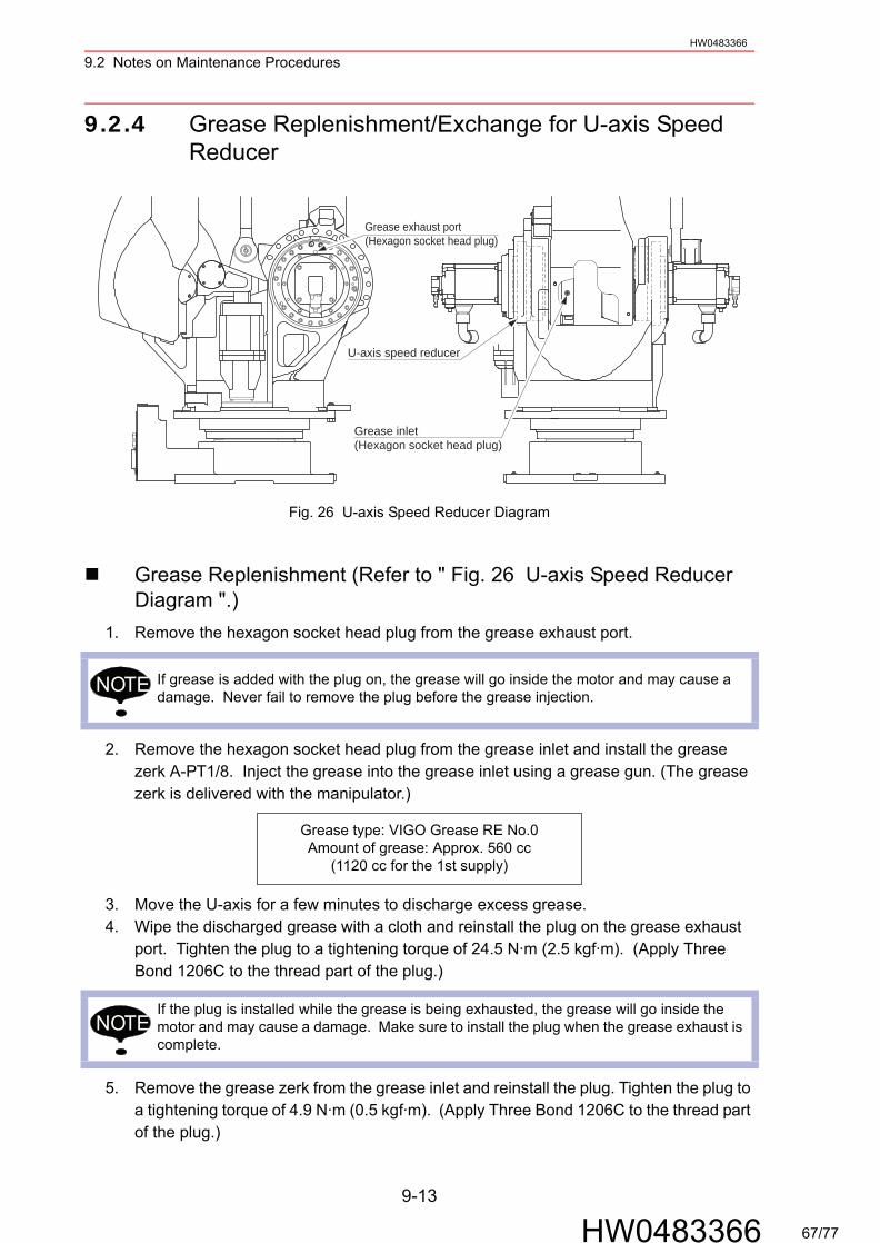
9.2 Notes on Maintenance ProceduresHW0483366
9.2.4 Grease Replenishment/Exchange for U-axis Speed Reducer
Fig. 26 U-axis Speed Reducer Diagram
Grease Replenishment (Refer to " Fig. 26 U-axis Speed Reducer Diagram ".)
1. Remove the hexagon socket head plug from the grease exhaust port.
2. Remove the hexagon socket head plug from the grease inlet and install the grease zerk A-PT1/8. Inject the grease into the grease inlet using a grease gun. (The grease zerk is delivered with the manipulator.)
3. Move the U-axis for a few minutes to discharge excess grease.4. Wipe the discharged grease with a cloth and reinstall the plug on the grease exhaust
port. Tighten the plug to a tightening torque of 24.5 N·m (2.5 kgf·m). (Apply Three Bond 1206C to the thread part of the plug.)
5. Remove the grease zerk from the grease inlet and reinstall the plug. Tighten the plug to a tightening torque of 4.9 N·m (0.5 kgf·m). (Apply Three Bond 1206C to the thread part of the plug.)
If grease is added with the plug on, the grease will go inside the motor and may cause a damage. Never fail to remove the plug before the grease injection.
Grease type: VIGO Grease RE No.0Amount of grease: Approx. 560 cc
(1120 cc for the 1st supply)
If the plug is installed while the grease is being exhausted, the grease will go inside the motor and may cause a damage. Make sure to install the plug when the grease exhaust is complete.
Grease exhaust port(Hexagon socket head plug)
U-axis speed reducer
Grease inlet(Hexagon socket head plug)
NOTE
NOTE
9-13
HW0483366 67/77
9.2 Notes on Maintenance ProceduresHW0483366
Grease Exchange (Refer to " Fig. 26 U-axis Speed Reducer Dia-gram ".)
1. Remove the hexagon socket head plug from the grease exhaust port.
2. Remove the hexagon socket head plug from the grease inlet and install the grease zerk A-PT1/8. Inject the grease into the grease inlet using a grease gun. (The grease zerk is delivered with the manipulator.)
3. The grease exchange is complete when new grease appears in the grease exhaust port. The new grease can be distinguished from the old grease by color.
4. Move the U-axis for a few minutes to discharge excess grease.5. Wipe the discharged grease with a cloth and reinstall the plug on the grease exhaust
port. Tighten the plug to a tightening torque of 24.5 N·m (2.5 kgf·m). (Apply Three Bond 1206C to the thread part of the plug.)
6. Remove the grease zerk from the grease inlet and reinstall the plug. Tighten the plug to a tightening torque of 4.9 N·m (0.5 kgf·m). (Apply Three Bond 1206C to the thread part of the plug.)
If grease is added with the plug on, the grease will go inside the motor and may cause a damage. Never fail to remove the plug before the grease injection.
Grease type: VIGO Grease RE No.0Amount of grease: Approx. 2800 cc
If the plug is installed while the grease is being exhausted, the grease will go inside the motor and may cause a damage. Make sure to install the plug when the grease exhaust is complete.
NOTE
NOTE
9-14
HW0483366 68/77
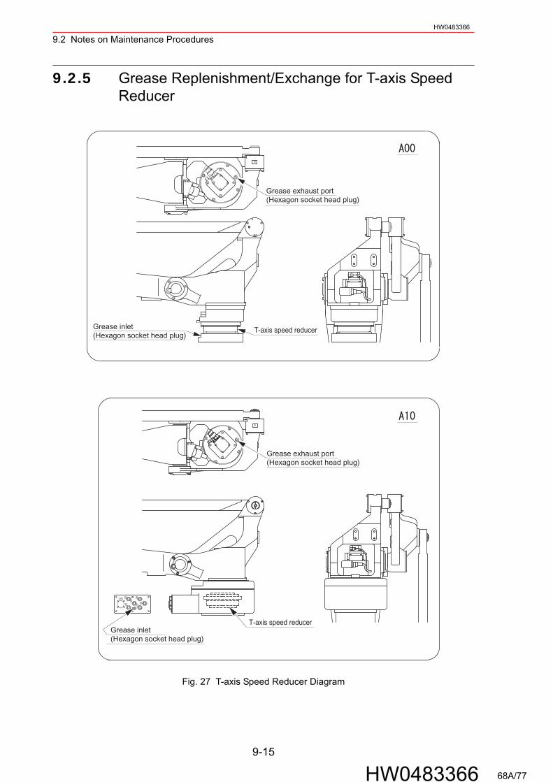
9.2 Notes on Maintenance Procedures
9-15
HW0483366
HW0483366
9.2.5 Grease Replenishment/Exchange for T-axis Speed Reducer
Fig. 27 T-axis Speed Reducer Diagram
Grease exhaust port(Hexagon socket head plug)
Grease inlet(Hexagon socket head plug)
T-axis speed reducer
Grease inlet(Hexagon socket head plug)
Grease exhaust port(Hexagon socket head plug)
T-axis speed reducer
68A/77
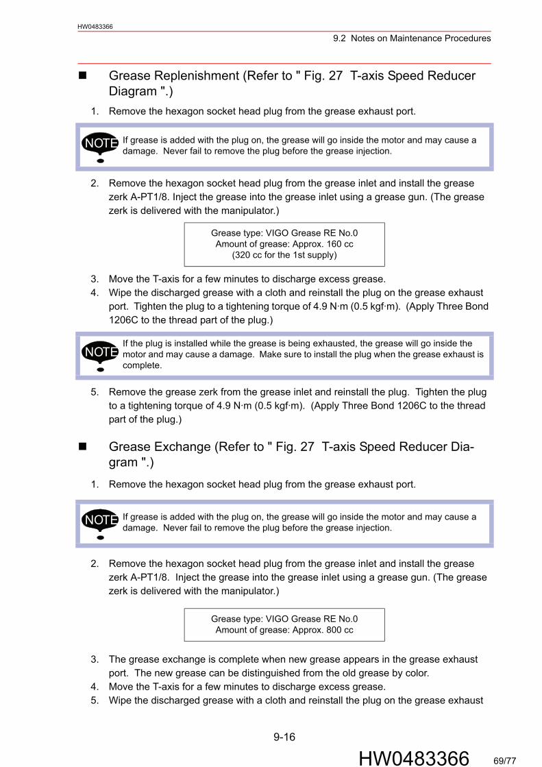
9.2 Notes on Maintenance Procedures
9-16
HW0483366
HW0483366
Grease Replenishment (Refer to " Fig. 27 T-axis Speed Reducer Diagram ".)
1. Remove the hexagon socket head plug from the grease exhaust port.
2. Remove the hexagon socket head plug from the grease inlet and install the grease zerk A-PT1/8. Inject the grease into the grease inlet using a grease gun. (The grease zerk is delivered with the manipulator.)
3. Move the T-axis for a few minutes to discharge excess grease.4. Wipe the discharged grease with a cloth and reinstall the plug on the grease exhaust
port. Tighten the plug to a tightening torque of 4.9 N·m (0.5 kgf·m). (Apply Three Bond 1206C to the thread part of the plug.)
5. Remove the grease zerk from the grease inlet and reinstall the plug. Tighten the plug to a tightening torque of 4.9 N·m (0.5 kgf·m). (Apply Three Bond 1206C to the thread part of the plug.)
Grease Exchange (Refer to " Fig. 27 T-axis Speed Reducer Dia-gram ".)
1. Remove the hexagon socket head plug from the grease exhaust port.
2. Remove the hexagon socket head plug from the grease inlet and install the grease zerk A-PT1/8. Inject the grease into the grease inlet using a grease gun. (The grease zerk is delivered with the manipulator.)
3. The grease exchange is complete when new grease appears in the grease exhaust port. The new grease can be distinguished from the old grease by color.
4. Move the T-axis for a few minutes to discharge excess grease.5. Wipe the discharged grease with a cloth and reinstall the plug on the grease exhaust
If grease is added with the plug on, the grease will go inside the motor and may cause a damage. Never fail to remove the plug before the grease injection.
Grease type: VIGO Grease RE No.0Amount of grease: Approx. 160 cc
(320 cc for the 1st supply)
If the plug is installed while the grease is being exhausted, the grease will go inside the motor and may cause a damage. Make sure to install the plug when the grease exhaust is complete.
If grease is added with the plug on, the grease will go inside the motor and may cause a damage. Never fail to remove the plug before the grease injection.
Grease type: VIGO Grease RE No.0Amount of grease: Approx. 800 cc
NOTE
NOTE
NOTE
69/77
9.2 Notes on Maintenance Procedures
9-17
HW0483366
HW0483366
port. Tighten the plug to a tightening torque of 4.9 N·m (0.5 kgf·m). (Apply Three Bond 1206C to the thread part of the plug.)
6. Remove the grease zerk from the grease inlet and reinstall the plug. Tighten the plug to a tightening torque of 4.9 N·m (0.5 kgf·m). (Apply Three Bond 1206C to the thread part of the plug.)
If the plug is installed while the grease is being exhausted, the grease will go inside the motor and may cause a damage. Make sure to install the plug when the grease exhaust is complete.
NOTE
70/77
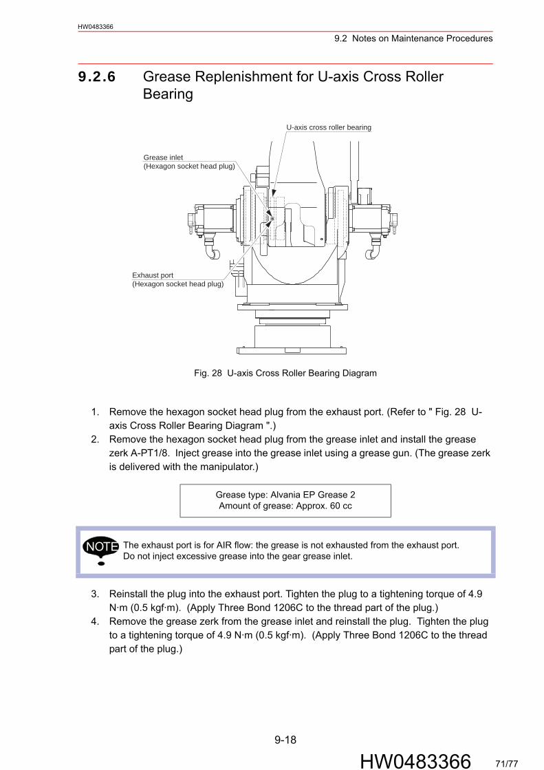
9.2 Notes on Maintenance Procedures
9-18
HW0483366
HW0483366
9.2.6 Grease Replenishment for U-axis Cross Roller Bearing
Fig. 28 U-axis Cross Roller Bearing Diagram
1. Remove the hexagon socket head plug from the exhaust port. (Refer to " Fig. 28 U-axis Cross Roller Bearing Diagram ".)
2. Remove the hexagon socket head plug from the grease inlet and install the grease zerk A-PT1/8. Inject grease into the grease inlet using a grease gun. (The grease zerk is delivered with the manipulator.)
3. Reinstall the plug into the exhaust port. Tighten the plug to a tightening torque of 4.9 N·m (0.5 kgf·m). (Apply Three Bond 1206C to the thread part of the plug.)
4. Remove the grease zerk from the grease inlet and reinstall the plug. Tighten the plug to a tightening torque of 4.9 N·m (0.5 kgf·m). (Apply Three Bond 1206C to the thread part of the plug.)
Grease type: Alvania EP Grease 2Amount of grease: Approx. 60 cc
The exhaust port is for AIR flow: the grease is not exhausted from the exhaust port. Do not inject excessive grease into the gear grease inlet.
U-axis cross roller bearing
Grease inlet(Hexagon socket head plug)
Exhaust port(Hexagon socket head plug)
NOTE
71/77
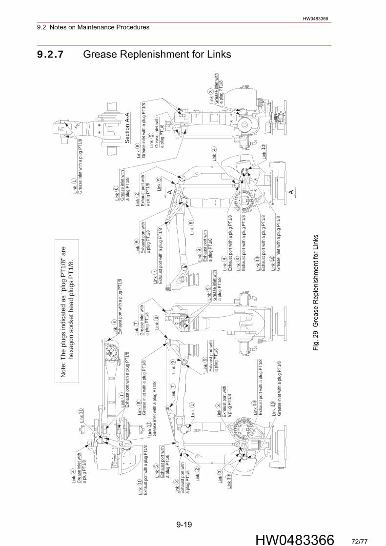
9.2 Notes on Maintenance Procedures
9-19
HW0483366
HW0483366
9.2.7 Grease Replenishment for Links
1BC
A
4BC
2BC
3BC
BDF
CE
A
DF
E BC
A
1
6
5
10
6 A
6
4
A
5
26
7
9
9
1010
10
33
9
1
7
79
8
8
8
2
2
511
11
1
11
4
Link
Gre
ase
inle
t with
a
plug
PT1
/8
Link
Exha
ust p
ort w
ith
a pl
ug P
T1/8
Link
Link
Exha
ust p
ort w
ith
a pl
ug P
T1/8
Link
Exha
ust p
ort w
ith a
plu
g PT
1/8
Link
Exha
ust p
ort w
ith
a pl
ug P
T1/8
Link
Gre
ase
inle
t with
a
plug
PT1
/84
Link
Exha
ust p
ort w
ith a
plu
g PT
1/8
3Li
nkEx
haus
t por
t with
a p
lug
PT1/
8
10Li
nkEx
haus
t por
t with
a p
lug
PT1/
8
10Li
nkG
reas
e in
let w
ith a
plu
g PT
1/8
Link Link
Link
Gre
ase
inle
t with
a
plug
PT1
/8
Link
Gre
ase
inle
t with
a p
lug
PT1/
8
Link
Gre
ase
inle
t with
a p
lug
PT1/
8
Link
Exha
ust p
ort w
ith a
plu
g PT
1/8
Link
Exha
ust p
ort w
ith a
plu
g PT
1/8
Link
Exha
ust p
ort w
ith
a pl
ug P
T1/8
Link
Exha
ust p
ort w
ith
a pl
ug P
T1/8
Link
Link
Link
Link
Gre
ase
inle
t with
a
plug
PT1
/8Li
nkG
reas
e in
let w
ith a
plu
g PT
1/8
Link
Gre
ase
inle
t with
a p
lug
PT1/
8
Link
Exha
ust p
ort w
ith
a pl
ug P
T1/8
Link
Exha
ust p
ort w
ith
a pl
ug P
T1/8
Link
Exha
ust p
ort w
ith a
plu
g PT
1/8
Link
Gre
ase
inle
t with
a p
lug
PT1/
8
Link
Gre
ase
inle
t with
a
plug
PT1
/8Li
nk Link
Link
Link
Link
Link
Sect
ion
A-A
3Li
nkG
reas
e in
let w
ith
a pl
ug P
T1/8
Not
e: T
he p
lugs
indi
cate
d as
"plu
g PT
1/8"
are
hex
agon
soc
ket h
ead
plug
s PT
1/8.
Link
Exha
ust p
ort w
ith a
plug P
T1/8
Fig.
29
Gre
ase
Rep
leni
shm
ent f
or L
inks
72/77

9.2 Notes on Maintenance Procedures
9-20
HW0483366
HW0483366
1. Remove the hexagon socket head plug PT1/8 from the exhaust port of each link. (Refer to " Fig. 29 Grease Replenishment for Links ".)
2. Remove the hexagon socket head plug PT1/8 from the grease inlet of each link and install the grease zerk A-PT1/8. Inject grease into the grease inlet using a grease gun. (The grease zerk is delivered with the manipulator.)
3. Reinstall the plug into the exhaust port of each link. Tighten the plug to a tightening torque of 4.9 N·m (0.5 kgf·m). (Apply Three Bond 1206C to the thread part of the plug.)
4. Remove the grease zerk from the grease inlet of each link and reinstall the plug. Tighten the plug to a tightening torque of 4.9 N·m (0.5 kgf·m). (Apply Three Bond 1206C to the thread part of the plug.)
Grease type Alvania EP Grease 2
Amount of grease
Links 6 cc (12 cc for the 1st supply)
Links 12 cc (24 cc for the 1st supply)
Links 3 cc (6 cc for the 1st supply)
Links 5 cc (10 cc for the 1st supply)
The exhaust port is for AIR flow: the grease is not exhausted from the exhaust port. Do not inject excessive grease into the gear grease inlet.
1 2 3 6
4 5 9
7 8
10 11
NOTE
73/77
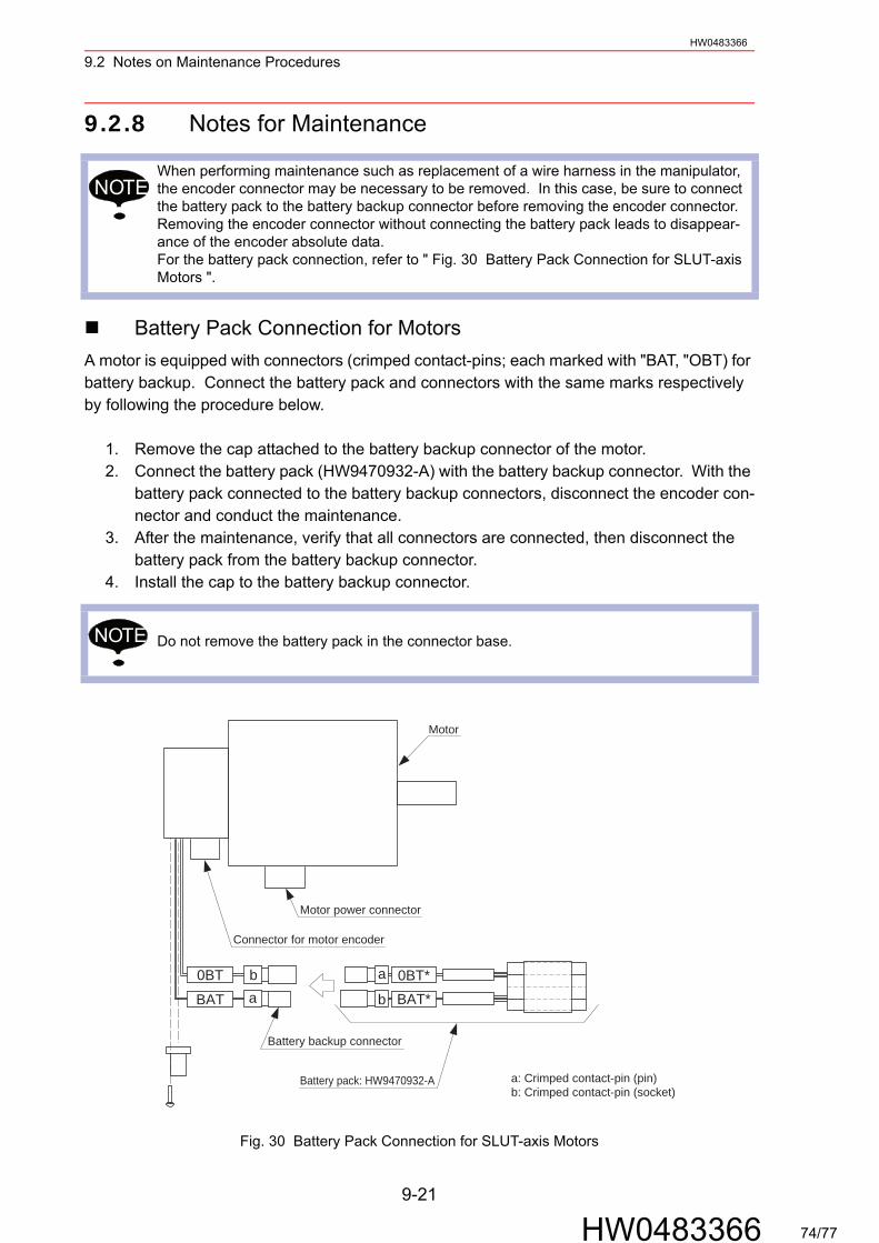
9.2 Notes on Maintenance Procedures
9-21
HW0483366
HW0483366
9.2.8 Notes for Maintenance
Battery Pack Connection for MotorsA motor is equipped with connectors (crimped contact-pins; each marked with "BAT, "OBT) for battery backup. Connect the battery pack and connectors with the same marks respectively by following the procedure below.
1. Remove the cap attached to the battery backup connector of the motor.2. Connect the battery pack (HW9470932-A) with the battery backup connector. With the
battery pack connected to the battery backup connectors, disconnect the encoder con-nector and conduct the maintenance.
3. After the maintenance, verify that all connectors are connected, then disconnect the battery pack from the battery backup connector.
4. Install the cap to the battery backup connector.
Fig. 30 Battery Pack Connection for SLUT-axis Motors
When performing maintenance such as replacement of a wire harness in the manipulator, the encoder connector may be necessary to be removed. In this case, be sure to connect the battery pack to the battery backup connector before removing the encoder connector.Removing the encoder connector without connecting the battery pack leads to disappear-ance of the encoder absolute data.For the battery pack connection, refer to " Fig. 30 Battery Pack Connection for SLUT-axis Motors ".
Do not remove the battery pack in the connector base.
NOTE
NOTE
b
aab0BT
BAT BAT*0BT*
Motor
Motor power connector
Connector for motor encoder
Battery pack: HW9470932-A
Battery backup connector
a: Crimped contact-pin (pin)b: Crimped contact-pin (socket)
74/77
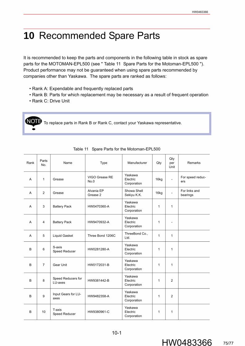
HW0483366
10 Recommended Spare Parts
It is recommended to keep the parts and components in the following table in stock as spare parts for the MOTOMAN-EPL500 (see " Table 11 Spare Parts for the Motoman-EPL500 "). Product performance may not be guaranteed when using spare parts recommended by companies other than Yaskawa. The spare parts are ranked as follows:
• Rank A: Expendable and frequently replaced parts• Rank B: Parts for which replacement may be necessary as a result of frequent operation• Rank C: Drive Unit
To replace parts in Rank B or Rank C, contact your Yaskawa representative.
Table 11 Spare Parts for the Motoman-EPL500
Rank PartsNo. Name Type Manufacturer Qty
QtyperUnit
Remarks
A 1 Grease VIGO Grease RE No.0
YaskawaElectricCorporation
16kg - For speed reduc-ers
A 2 Grease Alvania EPGrease 2
Showa Shell Sekiyu K.K. 16kg - For links and
bearings
A 3 Battery Pack HW0470360-AYaskawaElectricCorporation
1 1
A 4 Battery Pack HW9470932-AYaskawaElectricCorporation
1 -
A 5 Liquid Gasket Three Bond 1206C ThreeBond Co., Ltd. 1 1
B 6 S-axisSpeed Reducer HW0281280-A
YaskawaElectricCorporation
1 1
B 7 Gear Unit HW0172031-BYaskawaElectricCorporation
1 1
B 8 Speed Reducers for LU-axes HW9381442-B
YaskawaElectricCorporation
1 2
B 9 Input Gears for LU-axes HW9482358-A
YaskawaElectricCorporation
1 2
B 10 T-axisSpeed Reducer HW9380961-C
YaskawaElectricCorporation
1 1
NOTE
10-1
HW0483366 75/77
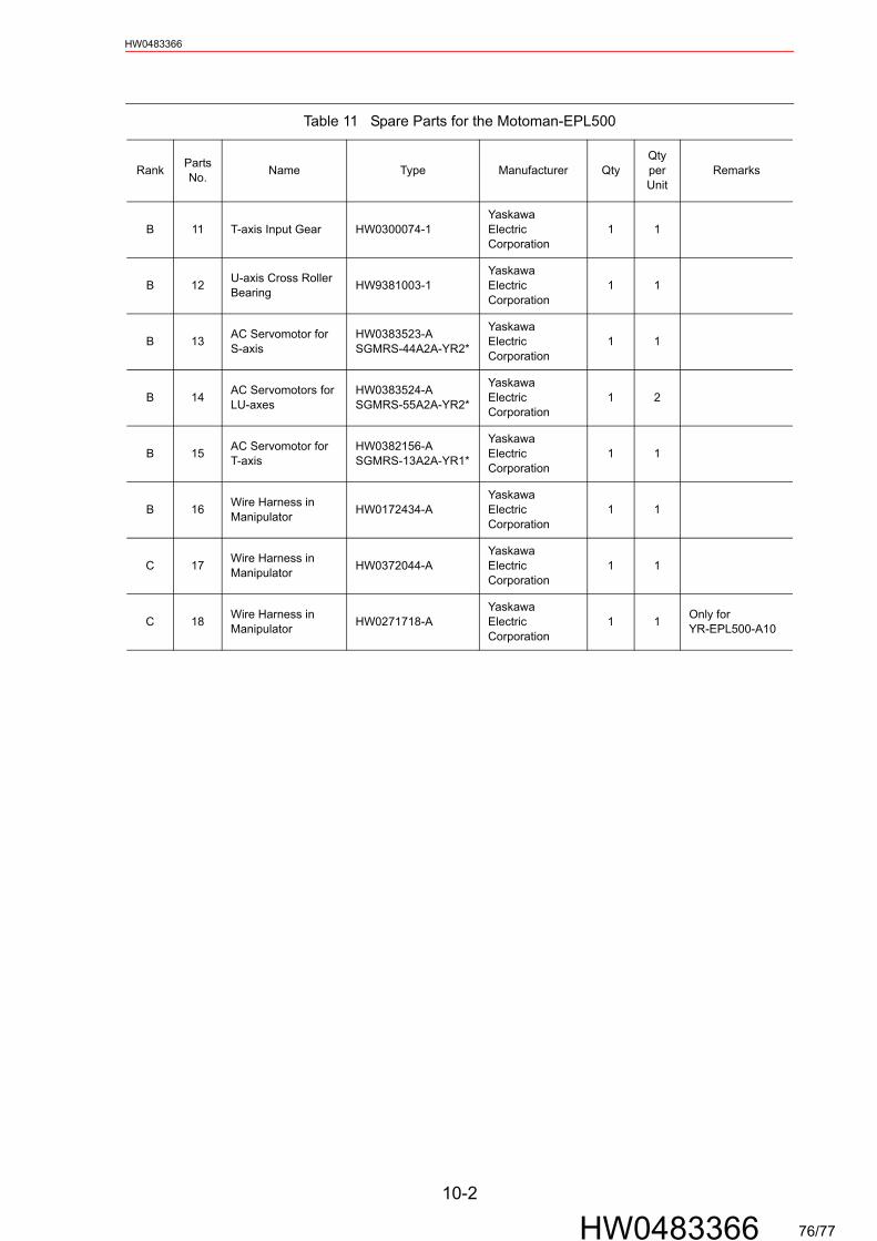
HW0483366
B 11 T-axis Input
B 12 U-axis CrossBearing
B 13 AC ServomoS-axis
B 14 AC ServomoLU-axes
B 15 AC ServomoT-axis
B 16 Wire HarnesManipulator
C 17 Wire HarnesManipulator
C 18 Wire HarnesManipulator
Rank PartsNo. Nam
Gear HW0300074-1YaskawaElectricCorporation
1 1
Roller HW9381003-1YaskawaElectricCorporation
1 1
tor for HW0383523-ASGMRS-44A2A-YR2*
YaskawaElectricCorporation
1 1
tors for HW0383524-ASGMRS-55A2A-YR2*
YaskawaElectricCorporation
1 2
tor for HW0382156-ASGMRS-13A2A-YR1*
YaskawaElectricCorporation
1 1
s in HW0172434-AYaskawaElectricCorporation
1 1
s in HW0372044-AYaskawaElectricCorporation
1 1
s in HW0271718-AYaskawaElectricCorporation
1 1 Only for YR-EPL500-A10
Table 11 Spare Parts for the Motoman-EPL500
e Type Manufacturer QtyQtyperUnit
Remarks
10-2
HW0483366 76/77

11.1 S-Axis Unit
11-1
HW0483366
HW0483366
11 Parts List
11.1 S-Axis Unit
1005
1006
1026
1027
1031
1001
1002
1013
1015
1008
1009
10101007
1017
1018
10191020
10321033
1036
1014
1011
1012
1003
1004
1030
1029
1022
10621063
1025
1028
10611041104010391061
1038
103910411042
1049
1046
1045
1049
105210511050
1060
1053
1056
1055
1054
1059
10581057
10481047
10441043
10441043
1037
1035
1034
1021
1023
1024
1016
76A/77
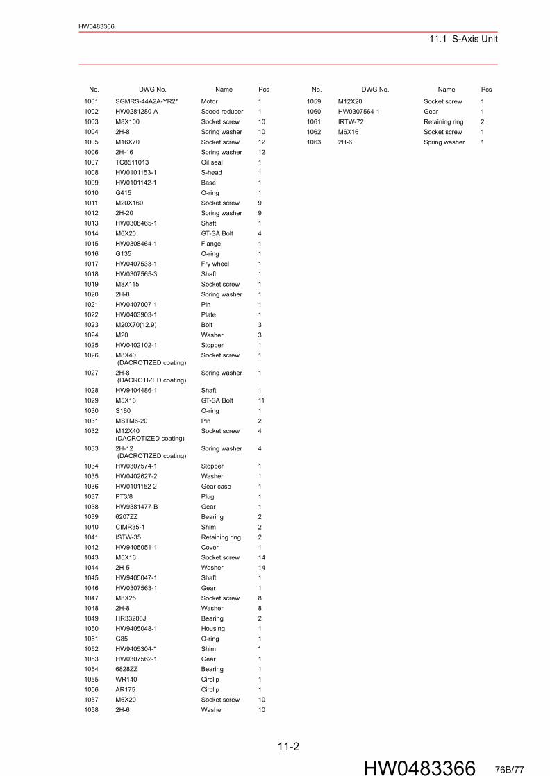
11.1 S-Axis Unit
11-2
HW0483366
HW0483366
No. DWG No. Name Pcs
1001 SGMRS-44A2A-YR2* Motor 11002 HW0281280-A Speed reducer 11003 M8X100 Socket screw 101004 2H-8 Spring washer 101005 M16X70 Socket screw 121006 2H-16 Spring washer 121007 TC8511013 Oil seal 11008 HW0101153-1 S-head 11009 HW0101142-1 Base 11010 G415 O-ring 11011 M20X160 Socket screw 91012 2H-20 Spring washer 91013 HW0308465-1 Shaft 11014 M6X20 GT-SA Bolt 41015 HW0308464-1 Flange 11016 G135 O-ring 11017 HW0407533-1 Fry wheel 11018 HW0307565-3 Shaft 11019 M8X115 Socket screw 11020 2H-8 Spring washer 11021 HW0407007-1 Pin 11022 HW0403903-1 Plate 11023 M20X70(12.9) Bolt 31024 M20 Washer 31025 HW0402102-1 Stopper 11026 M8X40
(DACROTIZED coating)Socket screw 1
1027 2H-8 (DACROTIZED coating)
Spring washer 1
1028 HW9404486-1 Shaft 11029 M5X16 GT-SA Bolt 111030 S180 O-ring 11031 MSTM6-20 Pin 21032 M12X40
(DACROTIZED coating)Socket screw 4
1033 2H-12 (DACROTIZED coating)
Spring washer 4
1034 HW0307574-1 Stopper 11035 HW0402627-2 Washer 11036 HW0101152-2 Gear case 11037 PT3/8 Plug 11038 HW9381477-B Gear 11039 6207ZZ Bearing 21040 CIMR35-1 Shim 21041 ISTW-35 Retaining ring 21042 HW9405051-1 Cover 11043 M5X16 Socket screw 141044 2H-5 Washer 141045 HW9405047-1 Shaft 11046 HW0307563-1 Gear 11047 M8X25 Socket screw 81048 2H-8 Washer 81049 HR33206J Bearing 21050 HW9405048-1 Housing 11051 G85 O-ring 11052 HW9405304-* Shim *1053 HW0307562-1 Gear 11054 6828ZZ Bearing 11055 WR140 Circlip 11056 AR175 Circlip 11057 M6X20 Socket screw 101058 2H-6 Washer 10
No. DWG No. Name Pcs
1059 M12X20 Socket screw 11060 HW0307564-1 Gear 11061 IRTW-72 Retaining ring 21062 M6X16 Socket screw 11063 2H-6 Spring washer 1
76B/77
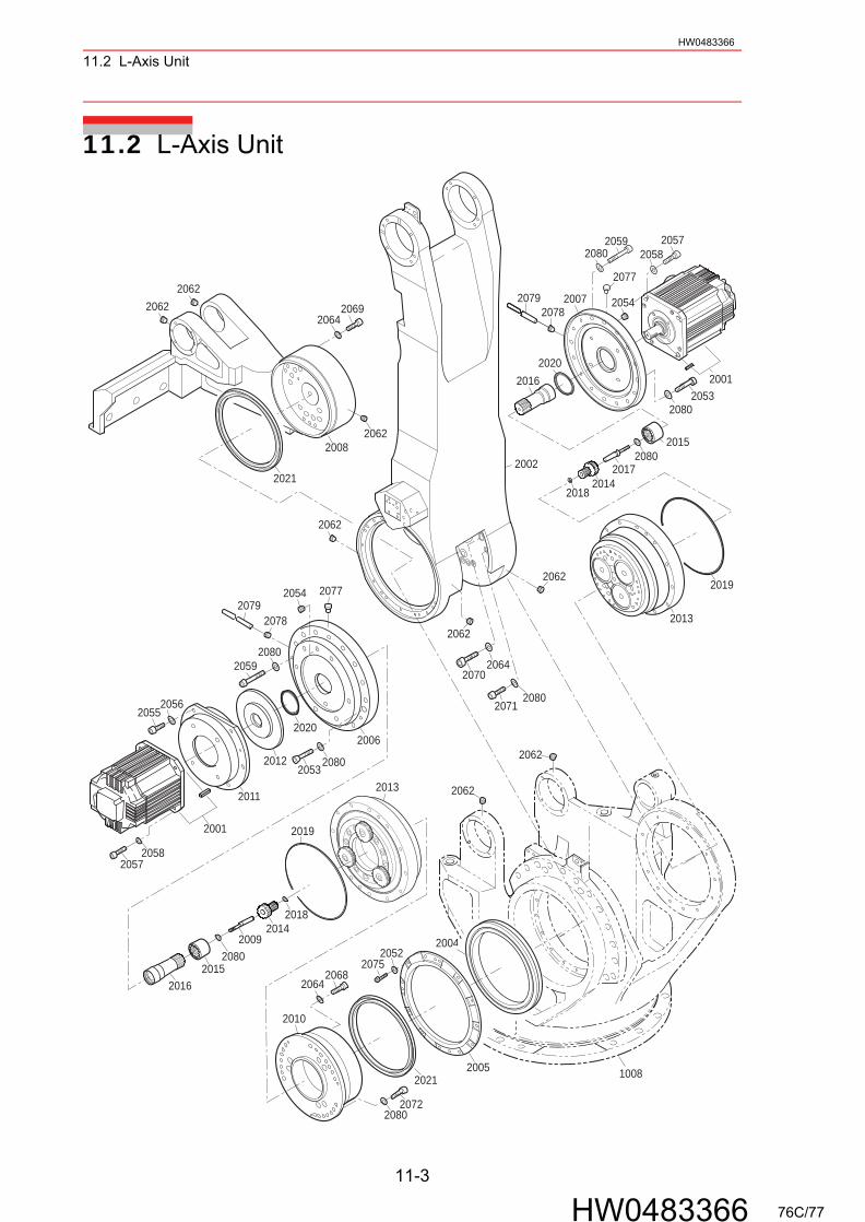
11.2 L-Axis UnitHW0483366
11.2 L-Axis Unit
2013
1008
2008
2010
20192001
2011
2064
20572058
2068
2006
2012
2020
2014
20152016
2009
20692064
20592080
20722080
2021
2004
2075
2002
2013
2018
2018
20172080
2014
2015
2079
2020
2007
2021
2001
2005
20572058
20592080
2071
2062
2080
2064
2019
2080
2054
2062
2062
2062
206220542062
2078
2078
2062
2052
2070
2077
2077
2016
2079
20552056
20532080
20532080
2062
11-3
HW0483366 76C/77
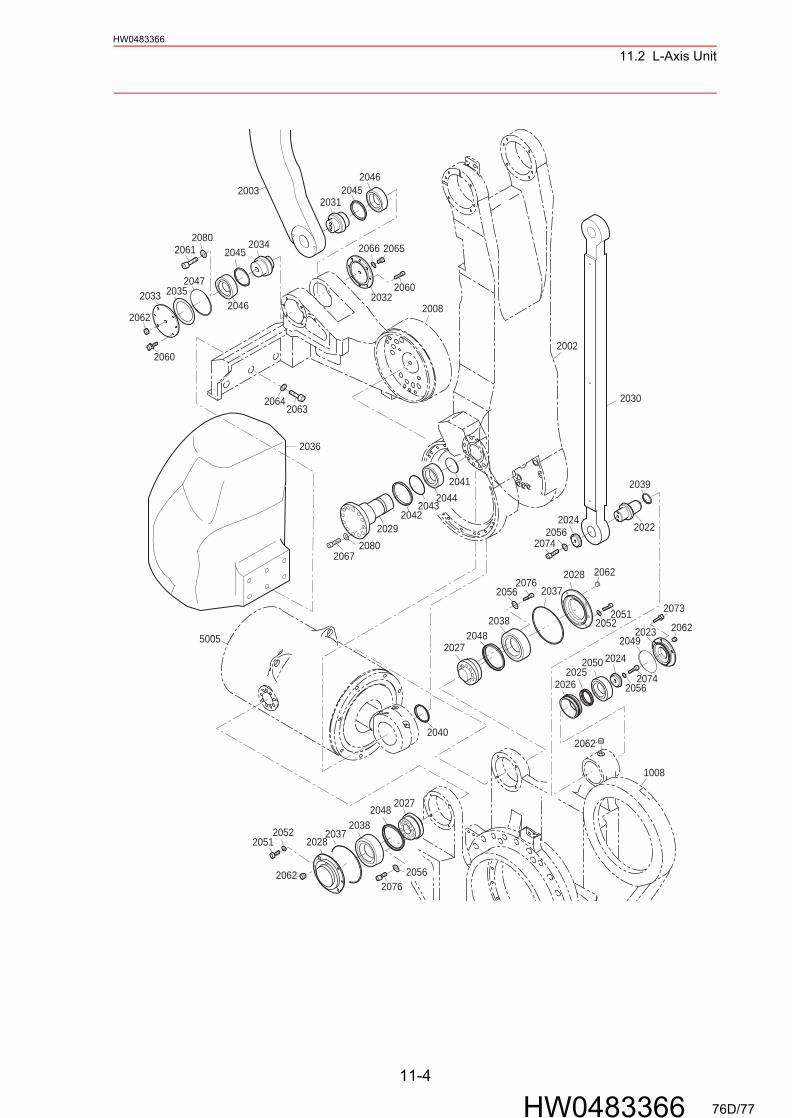
11.2 L-Axis UnitHW0483366
2048
2027
2027
2048
1008
2038
2038
2076
2076
2037
2037
2028
2028
2024
2041
2029
2024
2002
2030
20742056
20672080
2022
2039
2050
20262025
2023
2073
2051
2044
2049
2051
20742056
2062
2062
2062
2036
2045
2046
2047
2031
2033
2003
2008
20452046
20612080 2034 2065
2032
2060
2060
20632064
2062
5005
2040
20422043
2062
2035
2066
2056
2052
2056
2052
11-4
HW0483366 76D/77
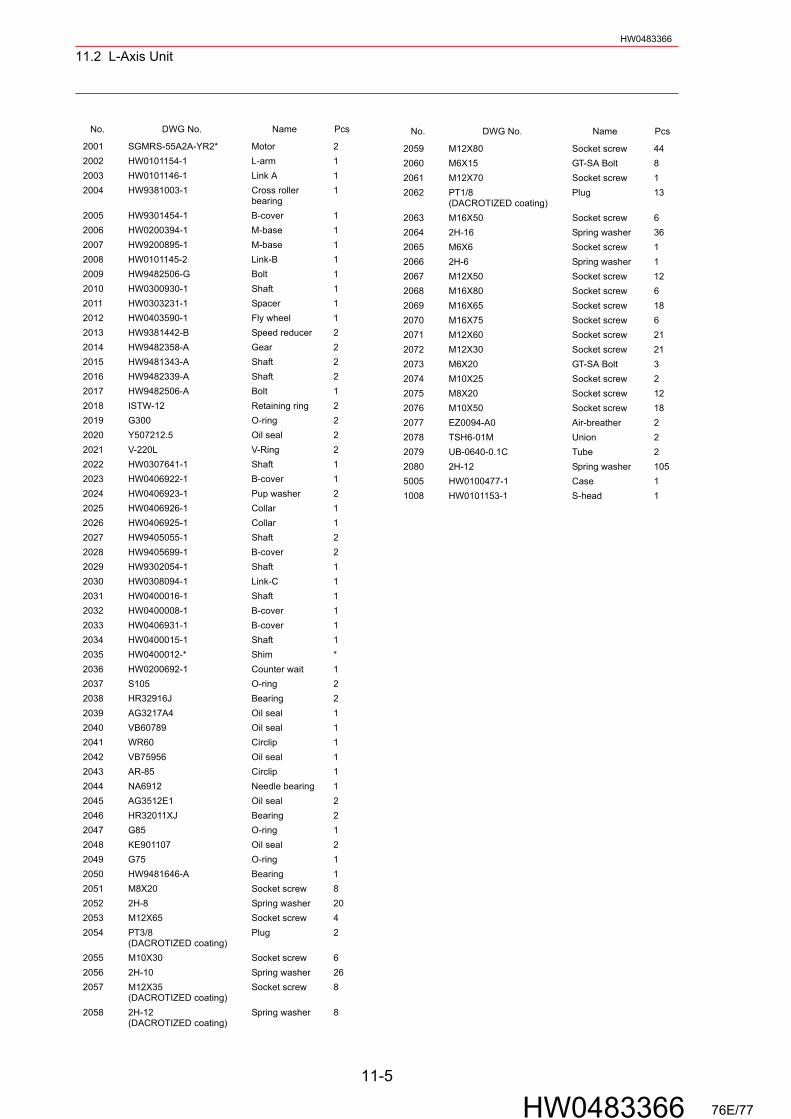
11.2 L-Axis Unit
11-5
HW0483366
HW0483366
No. DWG No. Name Pcs
2001 SGMRS-55A2A-YR2* Motor 22002 HW0101154-1 L-arm 12003 HW0101146-1 Link A 12004 HW9381003-1 Cross roller
bearing1
2005 HW9301454-1 B-cover 12006 HW0200394-1 M-base 12007 HW9200895-1 M-base 12008 HW0101145-2 Link-B 12009 HW9482506-G Bolt 12010 HW0300930-1 Shaft 12011 HW0303231-1 Spacer 12012 HW0403590-1 Fly wheel 12013 HW9381442-B Speed reducer 22014 HW9482358-A Gear 22015 HW9481343-A Shaft 22016 HW9482339-A Shaft 22017 HW9482506-A Bolt 12018 ISTW-12 Retaining ring 22019 G300 O-ring 22020 Y507212.5 Oil seal 22021 V-220L V-Ring 22022 HW0307641-1 Shaft 12023 HW0406922-1 B-cover 12024 HW0406923-1 Pup washer 22025 HW0406926-1 Collar 12026 HW0406925-1 Collar 12027 HW9405055-1 Shaft 22028 HW9405699-1 B-cover 22029 HW9302054-1 Shaft 12030 HW0308094-1 Link-C 12031 HW0400016-1 Shaft 12032 HW0400008-1 B-cover 12033 HW0406931-1 B-cover 12034 HW0400015-1 Shaft 12035 HW0400012-* Shim *2036 HW0200692-1 Counter wait 12037 S105 O-ring 22038 HR32916J Bearing 22039 AG3217A4 Oil seal 12040 VB60789 Oil seal 12041 WR60 Circlip 12042 VB75956 Oil seal 12043 AR-85 Circlip 12044 NA6912 Needle bearing 12045 AG3512E1 Oil seal 22046 HR32011XJ Bearing 22047 G85 O-ring 12048 KE901107 Oil seal 22049 G75 O-ring 12050 HW9481646-A Bearing 12051 M8X20 Socket screw 82052 2H-8 Spring washer 202053 M12X65 Socket screw 42054 PT3/8
(DACROTIZED coating)Plug 2
2055 M10X30 Socket screw 62056 2H-10 Spring washer 262057 M12X35
(DACROTIZED coating)Socket screw 8
2058 2H-12(DACROTIZED coating)
Spring washer 8
No. DWG No. Name Pcs
2059 M12X80 Socket screw 442060 M6X15 GT-SA Bolt 82061 M12X70 Socket screw 12062 PT1/8
(DACROTIZED coating)Plug 13
2063 M16X50 Socket screw 62064 2H-16 Spring washer 362065 M6X6 Socket screw 12066 2H-6 Spring washer 12067 M12X50 Socket screw 122068 M16X80 Socket screw 62069 M16X65 Socket screw 182070 M16X75 Socket screw 62071 M12X60 Socket screw 212072 M12X30 Socket screw 212073 M6X20 GT-SA Bolt 32074 M10X25 Socket screw 22075 M8X20 Socket screw 122076 M10X50 Socket screw 182077 EZ0094-A0 Air-breather 22078 TSH6-01M Union 22079 UB-0640-0.1C Tube 22080 2H-12 Spring washer 1055005 HW0100477-1 Case 11008 HW0101153-1 S-head 1
76E/77
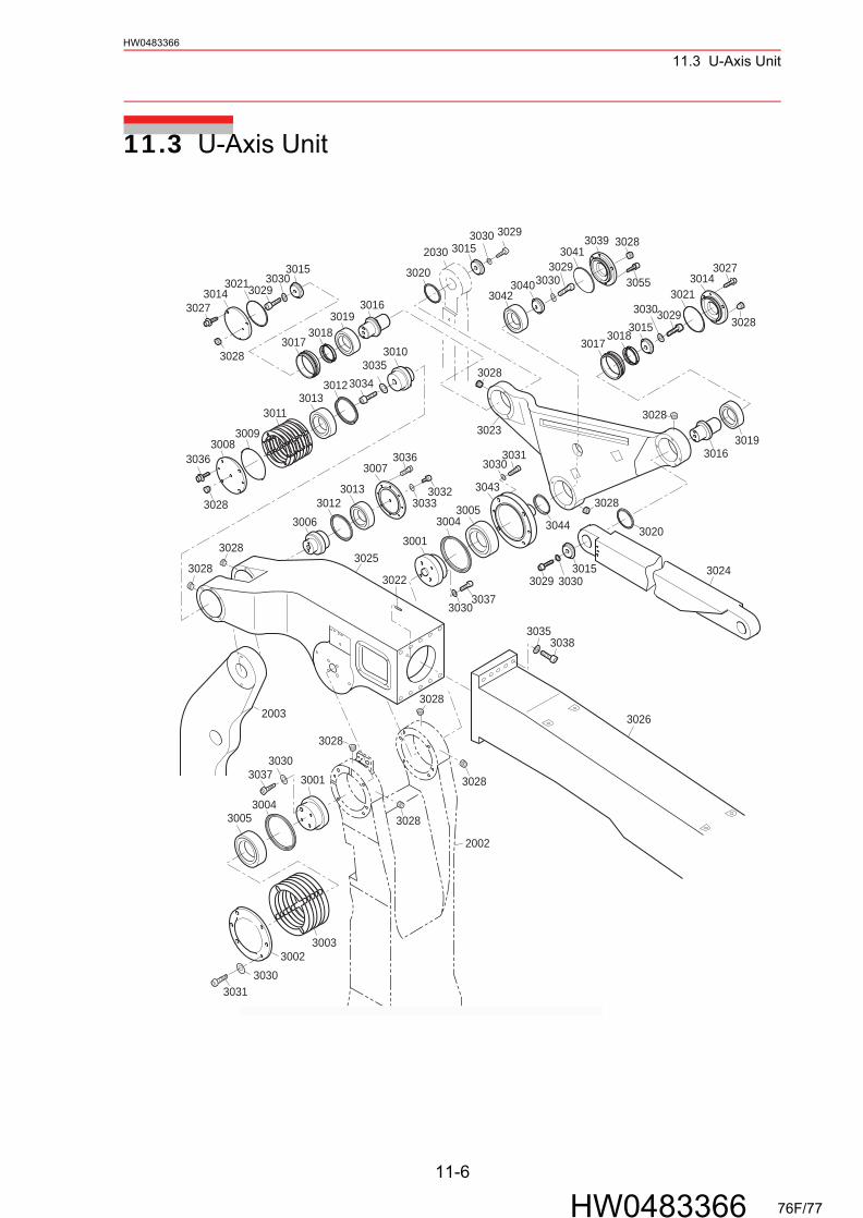
11.3 U-Axis Unit
11-6
HW0483366
HW0483366
11.3 U-Axis Unit
3001
3005
30053032
3033
30363036
3006
3007
30083009
3010
30343035
3031
3037
3043
3021
3041
3023
30243025
3026
3011
30123013
30023003
3004
3028
30013004
30123013
3015
3015
3015
3029 3030
3030
30293030
3016
3020
30173018
30193016
3020
3042
3044
30143014
3015 3029
302930303030
3039
3022
30383035
3027
2002
30183017
3019
2030
30553027
30293030
3030
3040
30303031
30303037
3021
3028
3028
3028
3028
3028
30283028
3028
3028
3028
3028
3028
2003
76F/77

11.3 U-Axis Unit
11-7
HW0483366
HW0483366
No. DWG No. Name Pcs
3001 HW9403571-2 Shaft 23002 HW9301405-1 B-cover 13003 HW9403656-* Shim *3004 AG4059E0 Oil seal 23005 HR32016XJ Bearing 23006 HW0400016-1 Shaft 13007 HW0400008-1 B-cover 13008 HW0406931-1 B-cover 13009 G85 O-ring 13010 HW0400015-1 Shaft 13011 HW0400012-* Shim *3012 AG3512E1 Oil seal 23013 HR32011XJ Bearing 23014 HW0406922-1 B-cover 23015 HW0406923-1 Pup washer 43016 HW0307641-1 Shaft 23017 HW0406925-1 Collar 23018 HW0406926-1 Collar 23019 HW9481646-A Bearing 23020 AG3217A4 Oil seal 23021 G75 O-ring 23022 MSTH6-10 Pin 23023 HW0200691-1 Link-D 13024 HW0308095-1 Link-E 13025 HW0101147-1 Casing 13026 HW0101155-1 U-arm 13027 M6X20 GT-SA Bolt 63028 PT1/8
(DACROTIZED coating)Plug 13
3029 M10X25 Socket screw 53030 2H-10 Spring washer 213031 M10X30 Socket screw 83032 M6X6 Socket screw 13033 2H-6 Spring washer 13034 M12X70 Socket screw 13035 2H-12 Spring washer 113036 M6X15 GT-SA Bolt 83037 M10X50 Socket screw 83038 M12X45 Socket screw 103039 HW0406822-1 B-cover 13040 HW0406759-1 Pup washer 13041 G95 O-ring 13042 HW0483232-A Bearing 13043 HW0306239-1 Shaft 13044 VC70X92X7 Oil seal 13055 M6X20 GT-SA Bolt 6*1
M6X20 GT-SA Bolt 3*2
2002 HW0101154-1 L-arm 12003 HW0101146-1 Link-A 12030 HW0308094-1 Link-C 1
*1 Component partsS5Q569-1 and after
*2 Component parts before S5Q569-1
76G/77
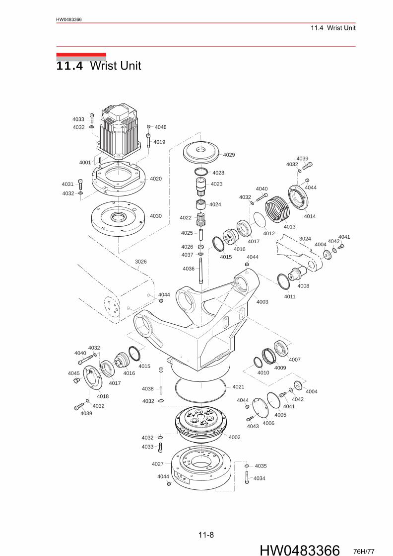
11.4 Wrist Unit
11-8
HW0483366
HW0483366
11.4 Wrist Unit
4032
4030
4039
4001
4003
4004
40054006
4007
4008
40094010
4011
4013
4014
4019
4021
4022
4023
4024
4025
4026
4028
4036
4037
4040
4041
4041
4042
4042
4039
4033
4043
4045
4004
4020
4002
4033
4032
4027
4038
4032
4034
4035
4044
4016
4016
4015
4015
4017
4017
40404032
4032
4012
4018
3026
4044
4044
4044
4044
40484032
4029
4031
4032
4032
3024
76H/77
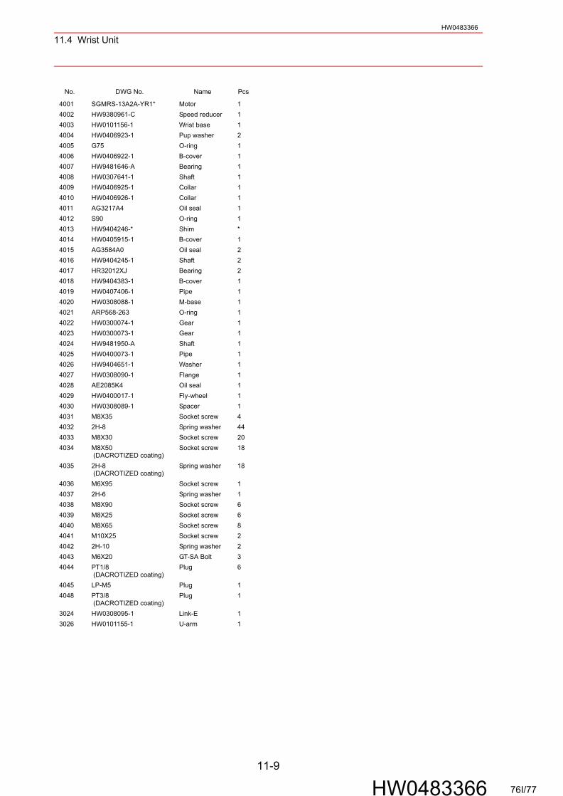
11.4 Wrist Unit
11-9
HW0483366
HW0483366
No. DWG No. Name Pcs
4001 SGMRS-13A2A-YR1* Motor 14002 HW9380961-C Speed reducer 14003 HW0101156-1 Wrist base 14004 HW0406923-1 Pup washer 24005 G75 O-ring 14006 HW0406922-1 B-cover 14007 HW9481646-A Bearing 14008 HW0307641-1 Shaft 14009 HW0406925-1 Collar 14010 HW0406926-1 Collar 14011 AG3217A4 Oil seal 14012 S90 O-ring 14013 HW9404246-* Shim *4014 HW0405915-1 B-cover 14015 AG3584A0 Oil seal 24016 HW9404245-1 Shaft 24017 HR32012XJ Bearing 24018 HW9404383-1 B-cover 14019 HW0407406-1 Pipe 14020 HW0308088-1 M-base 14021 ARP568-263 O-ring 14022 HW0300074-1 Gear 14023 HW0300073-1 Gear 14024 HW9481950-A Shaft 14025 HW0400073-1 Pipe 14026 HW9404651-1 Washer 14027 HW0308090-1 Flange 14028 AE2085K4 Oil seal 14029 HW0400017-1 Fly-wheel 14030 HW0308089-1 Spacer 14031 M8X35 Socket screw 44032 2H-8 Spring washer 444033 M8X30 Socket screw 204034 M8X50
(DACROTIZED coating)Socket screw 18
4035 2H-8 (DACROTIZED coating)
Spring washer 18
4036 M6X95 Socket screw 14037 2H-6 Spring washer 14038 M8X90 Socket screw 64039 M8X25 Socket screw 64040 M8X65 Socket screw 84041 M10X25 Socket screw 24042 2H-10 Spring washer 24043 M6X20 GT-SA Bolt 34044 PT1/8
(DACROTIZED coating)Plug 6
4045 LP-M5 Plug 14048 PT3/8
(DACROTIZED coating)Plug 1
3024 HW0308095-1 Link-E 13026 HW0101155-1 U-arm 1
76I/77
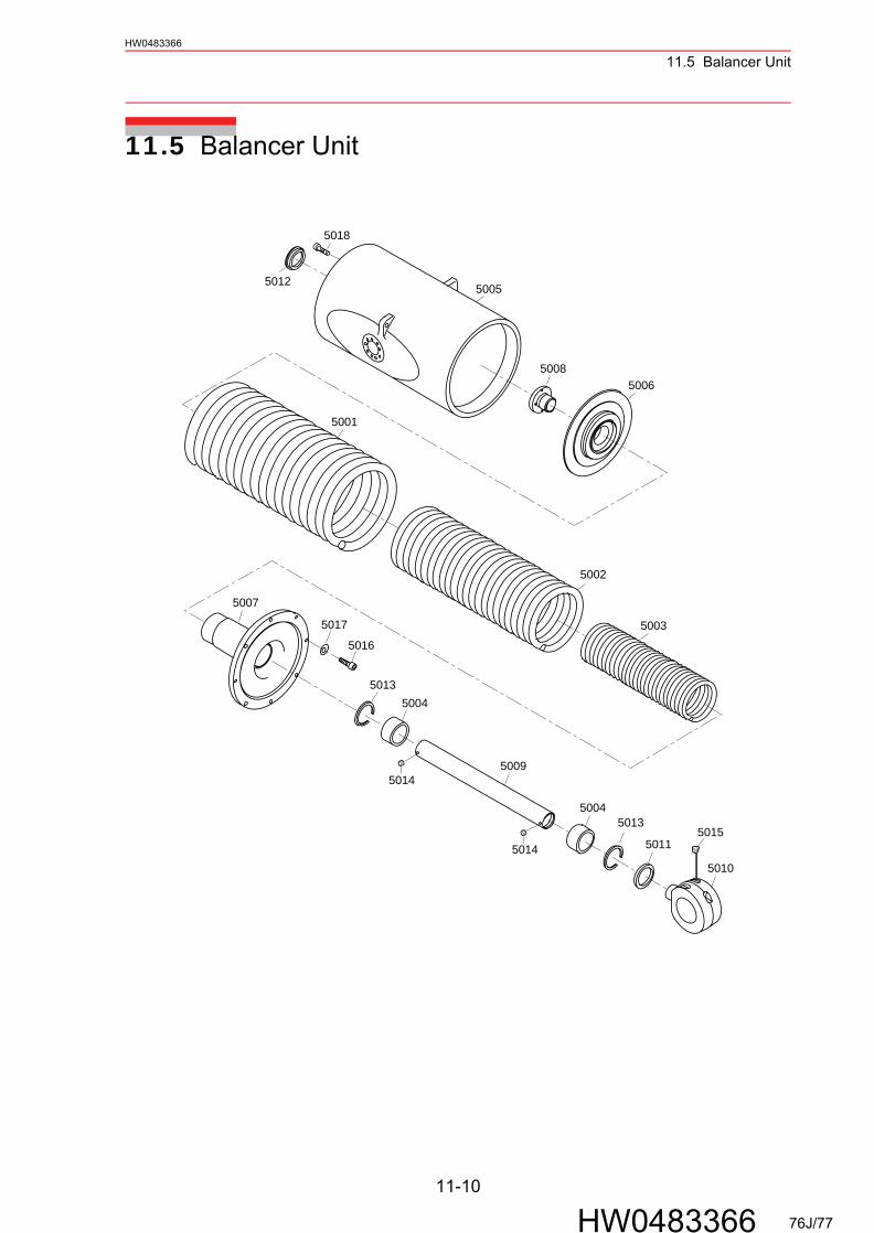
11.5 Balancer Unit
11-10
HW0483366
HW0483366
11.5 Balancer Unit
5001
5002
5003
5004
5005
5006
5007
5008
5009
5010
5011
5012
5018
5013
5013
50145015
5016
5017
5004
5014
76J/77

11.5 Balancer Unit
11-11
HW0483366
HW0483366
No. DWG No. Name Pcs
5001 HW0481740-A Coil spring 15002 HW0481741-A Coil spring 15003 HW0481742-A Coil spring 15004 SOB607440 Oiless 25005 HW0100477-1 Case 15006 HW0306033-1 Flange 15007 HW0200420-1 Flange 15008 HW0401112-1 Flange 15009 HW0303581-1 Rod 15010 HW9405057-1 Clevis 15011 FD3187A0 Dust seal 15012 EZ2228B0 Cap 15013 IRTW-75 Retaining ring 25014 M6X8 Magic screw 25015 PT1/8 Plug 35016 M10X40 Socket screw 85017 2H-10 Spring washer 85018 M8X16 GT-SA Bolt 3
76K/77
YASKAWA
YASKAWA EL
Specifications are subject to change wfor ongoing product modifications and
MOTOMANINSTRUCT
HEAD OFFICE2-1 Kurosaki-Shiroishi, YahataPhone 81-93-645-7745
MOTOMAN INC. HEADQUART805 Liberty Lane West CarrollPhone 1-937-847-6200YASKAWA MOTOMAN CANA3530 Laird Road, Unit 3, MissiPhone 1-905-569-6686MOTOMAN ROBOTICS EUROFranska Vagen 1039854, KalmPhone 46-480-417800MOTOMAN ROBOTEC GmbHKammerf eld strasse 1, DE-85Phone 49-8166-90100YASKAWA ELECTRIC KOREA1F Samy ang Bldg. 89-1, ShincPhone 82-53-745-7844
YASKAWA ELECTRIC (SINGA151 Lorong Chuan, #04-01, NPhone 65-6282-3003YASKAWA ELECTRIC (MALAYNo.71, Jalan Bandar Rawang Phone 60-3-6092-1377YASKAWA ELECTRIC TAIWA9F, 16 Nanking E. Rd., Sec. 3Phone 886-2-2502-5003SHOUGANG MOTOMAN ROB7,Yongchang-North Road, BePhone 86-10-6788-0541
-EPL500IONS
nishi-ku, Kitaky usy u-shi, 806-0004, JapanFax 81-93-645-7746
ERSton, OH 45449, U.S.A.
Fax 1-937-847-6277DA LTD.ssauga, Ontario, L5L 5Z7, Canada
Fax 1-905-813-5911PE AB
ar, SwedenFax 46-480-417999
391 Allershausen, GermanyFax 49-8166-90103
CORPORATIONhun-dong, Donk-Ku, Daegu, KoreaFax 82-2-784-8495
PORE) PTE. LTD.ew Tech Park, Singapore 556741, Singapore
Fax 65-6289-3003SIA) SDN. BHD.
2, 48000 Rawang, Selangor D.E., Malay siaFax 60-3-6092-6377
N CORPORATION, Taipei, Taiwan
Fax 886-2-2505-1280OT CO., LTD.ijing Economic & Technological Dev elopment Area, Beijing 100076, China
Fax 86-10-6788-2878
ECTRIC CORPORATION
ithout notice improvements. Printed in Japan September 2006 06-03C
HW0483366MANUAL NO.
2 77/77


![[Review of NX100 + 20-50mm lens] Performance of the NX100](https://img.pdfslide.net/doc/110x75/568bef531a28ab89338bc1ae/review-of-nx100-20-50mm-lens-performance-of-the-nx100-56e22b1aa4607.jpg)