Embed Size (px)
Citation preview
NX70/NX700 Series Analog Modules (A/D, D/A, RTD, TC) User Manual
Important User InformationSolid state equipment has operational characteristics differing from those of electromechanical equipment. Because of these differences, and also because of the wide variety of uses for solid state equipment, all persons responsible for applying this equipment must satisfy themselves that each intended application of this equipment is acceptable.
In no event will Rockwell Samsung Automation be responsible or liable for indirect or consequential damages resulting from the use or application of this equipment.
The examples and diagrams in this manual are included solely for illustrative purposes. Because of the many variables and requirements associated with any particular installation, Rockwell Samsung Automation cannot assume responsibility or liability for actual use based on the examples and diagrams.
No patent liability is assumed by Rockwell Samsung Automation. with respect to use of information, circuits, equipment, or software described in this manual.
Reproduction of the contents of this manual, in whole or in part, without written permission of Rockwell Samsung Automation. is prohibited.
Throughout this manual we use notes to make you aware of safety considerations.
WARNINGIdentifies information about practices or circumstances which may lead to serious personal injury or death, property damage, or economic loss.
IMPORTANT Identifies information that is critical for successful application and understanding of the product.
ATTENTION Identifies information about practices or circumstances that can lead to minor personal injury, property damage, economic loss, or product malfunction. However, depending on circumstances, failure to follow the directions accompanying this symbol may also lead to serious consequences.
Contents
1. Specifications ............................................................. 9General Specifications.................................................................................... 9NX70, NX700 Analog Modules (V2.1) ......................................................... 10NX70, NX700 Analog Module (V2.1) Features ........................................... 12
2. A/D Conversion Module ............................................ 13A/D Conversion Module Specifications ...................................................... 15Hardware Features........................................................................................ 17Input Range Selection .................................................................................. 19I/O Method for CPU Module......................................................................... 21I/O Conversion Characteristics..................................................................... 23Shared Memory Usage for A/D Conversion Module ................................. 25A/D Conversion Module Operating Procedure........................................... 27Programming ................................................................................................ 28
3. D/A Conversion Module ............................................ 31D/A Conversion Module Specifications ...................................................... 33Hardware Features........................................................................................ 35Selection Output Range ............................................................................... 39I/O Method for CPU Module......................................................................... 41I/O Conversion Characteristics..................................................................... 43Shared Memory Type Programming (SW8: ON) ..................................................................................................... 46D/A Conversion Module Operating Procedure........................................... 48D/A Module Wiring Diagram........................................................................ 49Programming ................................................................................................ 50
4. RTD Conversion Module ........................................... 53RTD Conversion Module Specifications ..................................................... 55RTD Module................................................................................................... 56For NX70 PLC System .................................................................................. 57RTD Module Input Range Selection ............................................................ 58I/O Method for CPU Module......................................................................... 59I/O Conversion Characteristics..................................................................... 61Shared Memory Usage for RTD Conversion Module ................................ 63RTD Conversion Module Operating Procedure.......................................... 65RTD Conversion Module Wiring Diagram .................................................. 66Programming ................................................................................................ 67
3
4
Shared Memory Type Programming (SW8: ON) ....................................... 68
5. TC Conversion Module.............................................. 71TC Conversion Module Specification.......................................................... 73TC Conversion Module................................................................................. 74TC Conversion Module Input Range Selection .......................................... 76I/O Method for CPU Module......................................................................... 78I/O Conversion Characteristics..................................................................... 80Shared Memory Usage for TC Conversion Module................................... 82TC Conversion Module Operating Procedure ............................................ 84TC Conversion Module Wiring Diagram..................................................... 85Programming ................................................................................................ 86
6. Product Dimensions and Installation........................ 89NX700 PLC Product Dimensions ................................................................. 89NX70 PLC Product Dimensions ................................................................... 91Mounting/Dismounting Module .................................................................. 93
Safety InstructionsPlease read this manual and the related documentation thoroughly and familiarize yourself with product information, safety instructions and other directions before installing, operating, performing inspection and preventive maintenance. Make sure to follow the directions correctly to ensure normal operation of the product and your safety.
WARNING • If this product is used in a situation that may cause personal injury and/or significant product damage, implement safe measures such as use of fault-safe equipment.
• Do not use this product under any conditions exposed to explosive gases. It may cause an explosion.
ATTENTION • Make sure to use an external device when configuring the protective circuit breakers for emergencies or interlock circuits.
• Fasten the terminal screws tightly to ensure that the cable connection is secure. Incorrect cable connection may cause overheating and product malfunction.
• Operate and keep the product under the allowed conditions directed in product specifications.Otherwise it may cause overheating and product malfunction.
• Do not disassemble or remodel the product.Otherwise it may cause an electric shock or malfunction.
• Do not touch the terminals when the power is on.Otherwise it may cause an electric shock.
5
6
Installation Environment
ATTENTION Do not install your unit if any of the following conditions are present:
• Ambient temperature outside the range of 0 to 55 °C (32 to 131 °F).
• Direct sunlight.
• Humidity outside the range of 30% to 85% (Non-condensing).
• Chemicals that may affect electronic parts.
• Excessive or conductive dust, or salinity.
• High voltage, strong magnetic fields, or strong electromagnetic influences.
• Direct impact and excessive vibration.
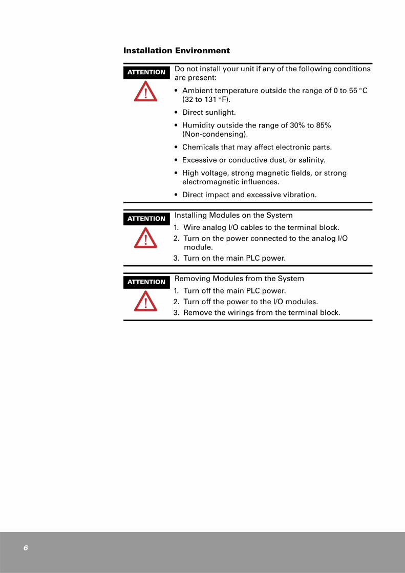
ATTENTION Installing Modules on the System
1. Wire analog I/O cables to the terminal block.2. Turn on the power connected to the analog I/O
module.3. Turn on the main PLC power.
ATTENTION Removing Modules from the System
1. Turn off the main PLC power.2. Turn off the power to the I/O modules.3. Remove the wirings from the terminal block.

ATTENTION Preventing PLC System Malfunctions
• Use an isolation transformer and line filter on the incoming power to the PLC when there is equipment using or producing high current, high voltage, or large magnetic fields in the vicinity.
• Use analog sensor that meets the rated specifications for module connection. Otherwise, it may cause operation errors.
• Separate the main PLC power line ground from all other power grounds. Always use class 3 grounding.
• Do not exceed the current and power rating of the external 24 VDC provided by the PLC power supply.
• Avoid system faults due to programming errors by reading and fully understanding this system manual and the PLC instruction set.
• Perform regular preventive maintenance on installed systems, checking devices and wiring for potential breakdowns and failures.
ATTENTION Installing analog module
• Avoid installing analog module next to output module or power supply modules.
• Install analog modules as near the right edge of the motherboard as possible.
7
8
Precautions for A/D Conversion Module Operation
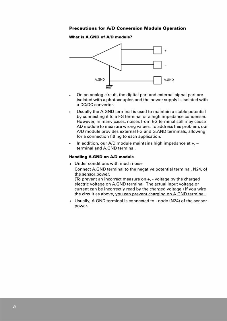
What is A.GND of A/D module?
£ On an analog circuit, the digital part and external signal part are isolated with a photocoupler, and the power supply is isolated with a DC/DC converter.
£ Usually the A.GND terminal is used to maintain a stable potential by connecting it to a FG terminal or a high impedance condenser. However, in many cases, noises from F.G terminal still may cause AD module to measure wrong values. To address this problem, our A/D module provides external FG and G.AND terminals, allowing for a connection fitting to each application.
£ In addition, our A/D module maintains high impedance at +, − terminal and A.GND terminal.
Handling A.GND on A/D module
k Under conditions with much noiseConnect A.GND terminal to the negative potential terminal, N24, of the sensor power.(To prevent an incorrect measure on +, - voltage by the charged electric voltage on A.GND terminal. The actual input voltage or current can be incorrectly read by the charged voltage.) If you wire the circuit as above, you can prevent charging on A.GND terminal.
k Usually, A.GND terminal is connected to - node (N24) of the sensor power.
A.GND A.GND
1
Specifications
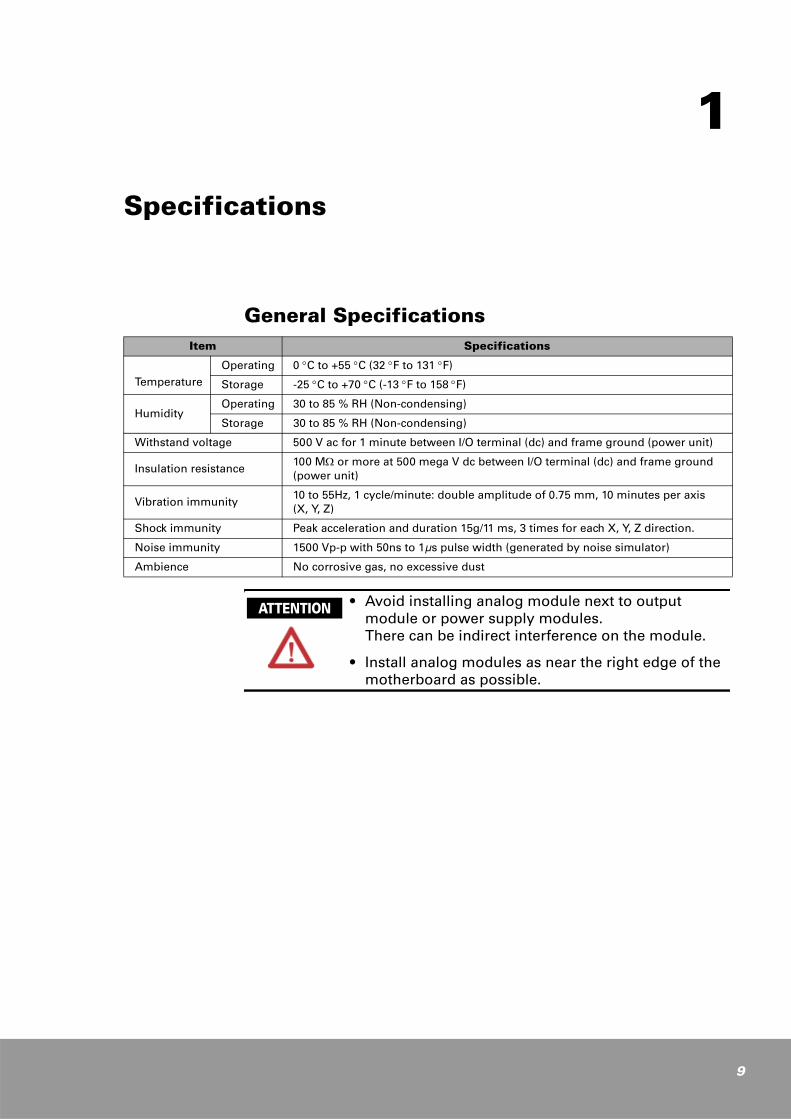
General Specifications
• Avoid installing analog module next to output module or power supply modules. There can be indirect interference on the module.
• Install analog modules as near the right edge of the motherboard as possible.
Item Specifications
Temperature
Operating 0 °C to +55 °C (32 °F to 131 °F)
Storage -25 °C to +70 °C (-13 °F to 158 °F)
HumidityOperating 30 to 85 % RH (Non-condensing)
Storage 30 to 85 % RH (Non-condensing)
Withstand voltage 500 V ac for 1 minute between I/O terminal (dc) and frame ground (power unit)
Insulation resistance100 MΩ or more at 500 mega V dc between I/O terminal (dc) and frame ground (power unit)
Vibration immunity10 to 55Hz, 1 cycle/minute: double amplitude of 0.75 mm, 10 minutes per axis (X, Y, Z)
Shock immunity Peak acceleration and duration 15g/11 ms, 3 times for each X, Y, Z direction.
Noise immunity 1500 Vp-p with 50ns to 1µs pulse width (generated by noise simulator)
Ambience No corrosive gas, no excessive dust
ATTENTION
9
10
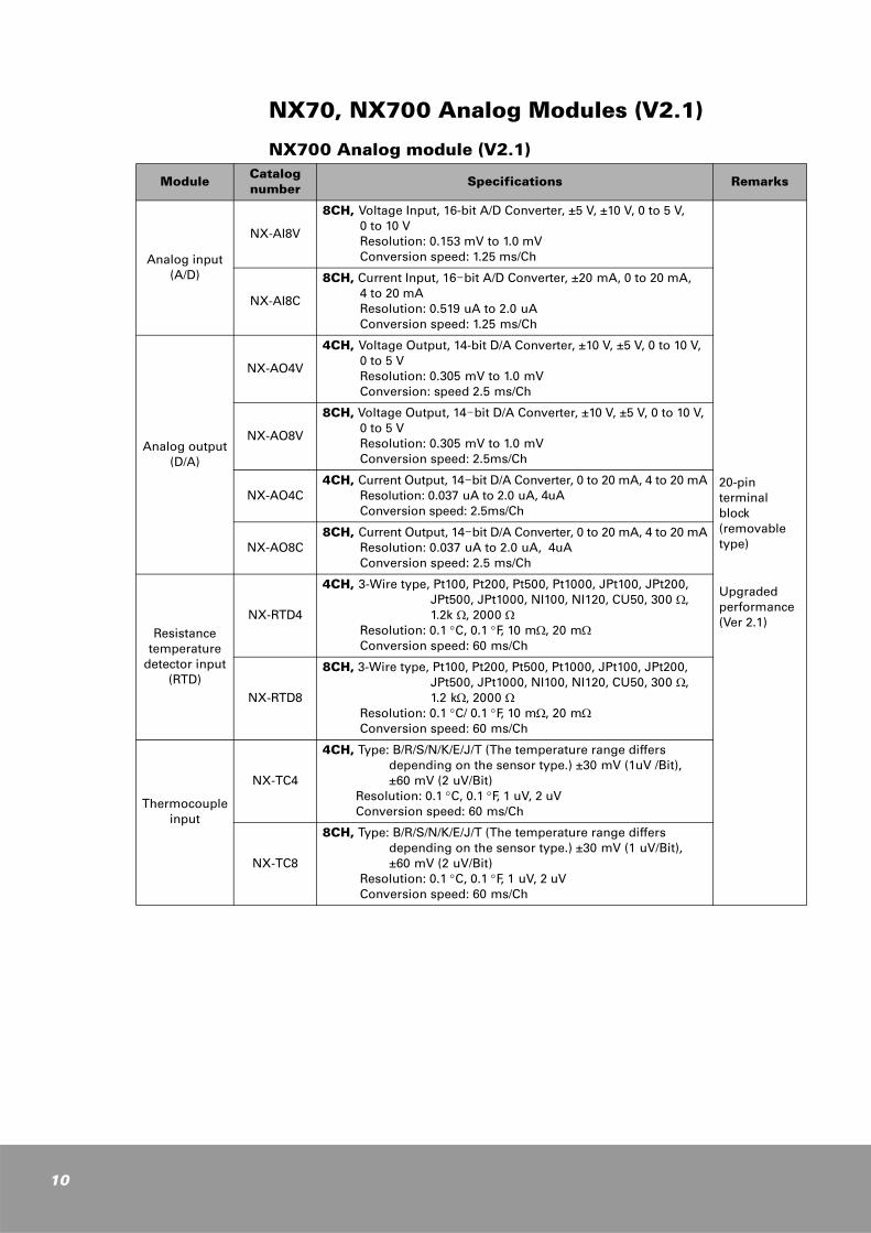
NX70, NX700 Analog Modules (V2.1)
NX700 Analog module (V2.1)
ModuleCatalog number Specifications Remarks
Analog input(A/D)
NX-AI8V
8CH, Voltage Input, 16-bit A/D Converter, ±5 V, ±10 V, 0 to 5 V, 0 to 10 V Resolution: 0.153 mV to 1.0 mVConversion speed: 1.25 ms/Ch
20-pin terminal block (removable type)
Upgraded performance(Ver 2.1)
NX-AI8C
8CH, Current Input, 16-bit A/D Converter, ±20 mA, 0 to 20 mA, 4 to 20 mA Resolution: 0.519 uA to 2.0 uAConversion speed: 1.25 ms/Ch
Analog output(D/A)
NX-AO4V
4CH, Voltage Output, 14-bit D/A Converter, ±10 V, ±5 V, 0 to 10 V, 0 to 5 V Resolution: 0.305 mV to 1.0 mVConversion: speed 2.5 ms/Ch
NX-AO8V
8CH, Voltage Output, 14-bit D/A Converter, ±10 V, ±5 V, 0 to 10 V, 0 to 5 V Resolution: 0.305 mV to 1.0 mVConversion speed: 2.5ms/Ch
NX-AO4C4CH, Current Output, 14-bit D/A Converter, 0 to 20 mA, 4 to 20 mA
Resolution: 0.037 uA to 2.0 uA, 4uAConversion speed: 2.5ms/Ch
NX-AO8C8CH, Current Output, 14-bit D/A Converter, 0 to 20 mA, 4 to 20 mA
Resolution: 0.037 uA to 2.0 uA, 4uAConversion speed: 2.5 ms/Ch
Resistance temperature
detector input(RTD)
NX-RTD4
4CH, 3-Wire type, Pt100, Pt200, Pt500, Pt1000, JPt100, JPt200, JPt500, JPt1000, NI100, NI120, CU50, 300 Ω,1.2k Ω, 2000 Ω
Resolution: 0.1 °C, 0.1 °F, 10 mΩ, 20 mΩConversion speed: 60 ms/Ch
NX-RTD8
8CH, 3-Wire type, Pt100, Pt200, Pt500, Pt1000, JPt100, JPt200, JPt500, JPt1000, NI100, NI120, CU50, 300 Ω,1.2 kΩ, 2000 Ω
Resolution: 0.1 °C/ 0.1 °F, 10 mΩ, 20 mΩConversion speed: 60 ms/Ch
Thermocouple input
NX-TC4
4CH, Type: B/R/S/N/K/E/J/T (The temperature range differs depending on the sensor type.) ±30 mV (1uV /Bit), ±60 mV (2 uV/Bit)
Resolution: 0.1 °C, 0.1 °F, 1 uV, 2 uVConversion speed: 60 ms/Ch
NX-TC8
8CH, Type: B/R/S/N/K/E/J/T (The temperature range differs depending on the sensor type.) ±30 mV (1 uV/Bit), ±60 mV (2 uV/Bit)
Resolution: 0.1 °C, 0.1 °F, 1 uV, 2 uVConversion speed: 60 ms/Ch

NX70 Analog module (V2.1)
Module Catalog number
Specifications Remarks
Analog input(A/D)
NX70-AI8V
8CH Voltage Input, 16-bit A/D Converter, ±5 V, ±10 V, 0 to 5 V, 0 to 10 V Resolution: 0.153 MTV to 1.0 mV)Conversion speed: 1.25 ms/Ch
20-pin terminal block type
Upgraded performance(Ver 2.1)
NX70-AI8C
8CH Current Input, 16-bit A/D Converter, ±20 mA, 0 to 20 mA, 4 to 20 mA Resolution: 0.519 uA to 2.0 uAConversion speed: 1.25 ms/Ch
NX70-AI4V
4CH Voltage Input, 16-bit A/D Converter, ±5 V, ±10 V, 0 to 5 V, 0 to 10 V Resolution: 0.153 MTV to 1.0 mVConversion speed: 1.25 ms/Ch
NX70-AI4C
4CH Current Input, 16-bit A/D Converter, ±20 mA, 0 to 20 mA, 4 to 20 mA Resolution: 0.519 uA to 2.0 uAConversion speed: 1.25 ms/Ch
Analog output(D/A)
NX70-AO4V
4CH Voltage Output, 14-bit D/A Converter, ±10 V, ±5 V, 0 to 10 V, 0 to 5V Resolution: 0.305 mV to 1.0 mVConversion speed: 2.5 ms/Ch
NX70-AO4C4CH Current Output, 14-bit D/A Converter, 0 to 20 mA, 4 to 20 mA
Resolution: 0.037 uA to 2.0 uA, 4 uAConversion speed: 2.5 ms/Ch
NX70-AO2V
2CH Voltage Output, 14-bit D/A Converter, ±10 V, ±5 V, 0 to 10 V, 0 to 5 V Resolution: 0.305 mV to 1.0 mVConversion speed: 2.5 ms/Ch
NX70-AO2C2CH Current Output, 14-bit D/A Converter, 0 to 20 mA, 4 to 20 mA
Resolution: 0.037 uA to 2.0 uA, 4uAConversion speed: 2.5 ms/Ch
Resistance temperature
detector input(RTD)
NX70-RTD4
4CH 3-Wire type, Pt100, Pt200, Pt500, Pt1000, JPt100, JPt200, JPt500, JPt1000, NI100, NI120, CU50, 300 Ω, 1.2 kΩ, 2000 Ω
Resolution: 0.1 °C, 0.1 °F, 10 mΩ, 20 mΩConversion speed: 60 ms/Ch
Thermocoupleinput
NX70 -TC4
4CH Type: B/R/S/N/K/E/J/T (The temperature range differs depending on the sensor type.) ±30 mV (1 uV/Bit), ±60 mV (2 uV/Bit)
Resolution: 0.1 °C, 0.1 °F, 1 uV, 2 uVConversion speed : 60 ms/Ch
11
12
NX70, NX700 Analog Module (V2.1) Features
Analog module (V2.1) features
• Conversion speed and resolution, the deciding factor for the performance of analog unit, are processed with high-speed and high-accuracy. Two programming methods-a method using shared memory and a method using I/O contacts-allow you to select an appropriate method according to the occupied I/O points.
• NX70, NX700 PLC analog modules are isolated from the internal circuit with a DC/DC converter and a photocoupler. Low current consumption is another advantage.
A/D module features
k Additional volume adjustment is not needed. 16-bit A/D Converter enables a wider input range, faster conversion speed, and higher Resolution (Selected with dip switch).
k Features high speed of 1.25ms/CH and high resolution. Provides max. resolution of 0.153 mV for voltage type and 0.519 uA for current type.
k Specifically, low current consumption has widened operation range, and 20-pin terminal block is used for external connection. (NX700 analog module uses removable terminal block.)
D/A module featuresk Additional volume adjustment is not needed. 14-bit D/A Converter
enables a wider input range, faster conversion speed, and higher resolution (Selected with dip switch).
k Wide channel range: For NX700, 4-channel and 8-channel D/A modules are availalde. For NX70, 2-channel and 4-channel D/A modules are available.
k Specifically, low current consumption has widened operation range, and 20-pin terminal is used for external connection. (NX700 analog module uses removable terminal block.)
RTD/Thermocouple module features
k 24-bit Σ-∆ A/D Converter enables fast speed and high accuracy, and wide I/O range. Self-calibration feature is also added. The built-in analog & digital noise filter gives a good improves resistance against environmental inferferences.
k RTD module implemented 3-wire connection type, which offsets the wire resistance. The 3-wired platinum temperature sensors (Pt100, Pt200, JPt100, JPt200....) support both Celsius (°C) and Fahrenheit (°F) data.
k TC module provides temperature compensation feature, and supports temperature sensor types of B, R, S, N, K, E, J, T, L, U, C and D.
k Specifically, low current consumption has widened operation range, and 20-pin terminal is used for external connection. (NX700 analog module uses removable terminal block.)
2
A/D Conversion Module
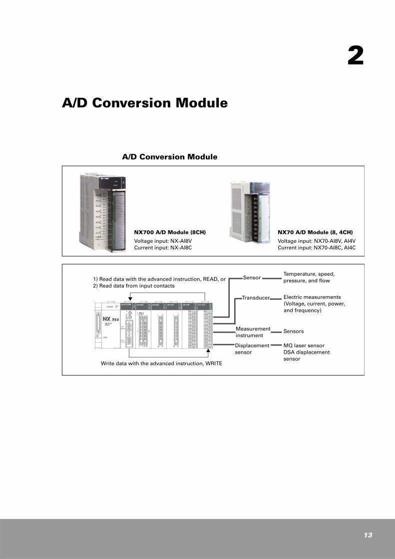
A/D Conversion Module
NX700 A/D Module (8CH)
Voltage input: NX-AI8V Current input: NX-AI8C
NX70 A/D Module (8, 4CH)
Voltage input: NX70-AI8V, AI4VCurrent input: NX70-AI8C, AI4C
1) Read data with the advanced instruction, READ, or2) Read data from input contacts
Sensor
Transducer
Measurement instrument
Displacement sensor
Temperature, speed, pressure, and flow
Electric measurements (Voltage, current, power, and frequency)
Sensors
MQ laser sensorDSA displacement sensor
Write data with the advanced instruction, WRITE
POWER
COMRS232C
TOOLRS232C
NX-CPU750B CPU
NX-X64D
DCIN
NX-X32D
DCIN
NX-Y32T
TROUT
NX-Y16R
RYOUT
NX-AI8C
ANALO
G
13
14
A/D Conversion Module Features
Additional volume adjustment is not required. Conversion speed and resolution, the deciding factor for the performance of analog unit, are processed with high-speed and high-accuracy.
1. NX700 A/D module: 8 channels/moduleNX70 A/D module: 4 or 8 channels/module
2. Highly improved resolutionProvides max. resolution of 0.153 mV for voltage type, and 0.519 uA for current type. You can select an appropriate resolution using the DIP switch.
3. DC/DC converter and/or photocoupler isolation between the input channels and the internal circuit.
4. Two programming methods Provide two programming methods. You can select an appropriate method according to the occupied I/O points:
Using shared memory Using I/O contacts
5. High speedThe A/D module is equipped with 16-bit A/D converter, providing high-accuracy conversion and high-speed processing of 1.25 ms per channel.

A/D Conversion Module Specifications
Voltage Input Module
*1. Both I/O characteristics and maximum resolution can be set to from high to average by selecting the DIP switch located on the bottom of the product. The conversion speed and stability for converted data depend on resolution. See "Input Range Selection" in Chapter 2.
Voltage Input: NX-AI8V, NX70-AI8V, NX70-AI4V
PLC Series NX700 Series NX70 Series
Catalog Number NX-AI8V NX70-AI8V NX70-AI4V
Analog input range Voltage: 0 to 10 V, 0 to 5 V, ±10 V, ±5 V
Digital conversion Signed 16-bit binary (2's complement)
Converter type 16-bit A/D converter
Number of analog input channels
8 Channels 8 Channels 4 Channels
I/O characteristics *1
0 to 10 V (0 to 32767), (0 to 20000), ……0 to 5 V (0 to 32767), (0 to 20000), ……±10 V (-32767 to 32767), ………… ±5 V (-32767 to 32767), …………
Max.resolution *1
0.153 mV, (0.305 mV), ……
Overall accuracy ±0.2 %/F.S (25 °C)
Conversion speed 1.25 ms per channel
External input impedance
500 kΩ
Absolute maximum input
voltage: ±15 V, current: ±30 mA
Isolation methodBetween input channel and internal circuit: DC/DC converter and photocoupler isolationBetween input channels: Non-isolation
Occupied I/O point
I/O contact type: NX700 (8 channels): 128 input pointsNX70: 128 input points for 8-channel module, 64 input points for 4-channel module
Shared memory type: 16 points
Other functions Channel On/Off switching
Internal current consumption (5V)
NX700: 5 V 270 mA or less NX70: 5 V 290 mA or less
External connection method
NX700: 20-pin removable terminal block (M3.5)
NX70: 20-pin terminal block (M3.0)
A/D conversion module
C stands for Common
A.GND must be connected to sensor power (-) terminal for stable operation.Shield
Signal source: 0 to 10 V, 0 to 5 V, ±10 V, ±5 V
15
16
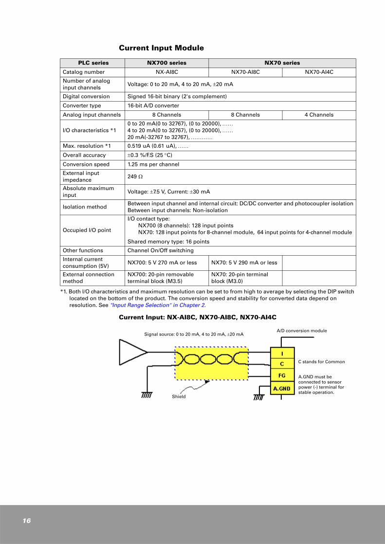
Current Input Module
*1. Both I/O characteristics and maximum resolution can be set to from high to average by selecting the DIP switch located on the bottom of the product. The conversion speed and stability for converted data depend on resolution. See "Input Range Selection" in Chapter 2.
Current Input: NX-AI8C, NX70-AI8C, NX70-AI4C
PLC series NX700 series NX70 series
Catalog number NX-AI8C NX70-AI8C NX70-AI4C
Number of analog input channels
Voltage: 0 to 20 mA, 4 to 20 mA, ±20 mA
Digital conversion Signed 16-bit binary (2's complement)
Converter type 16-bit A/D converter
Analog input channels 8 Channels 8 Channels 4 Channels
I/O characteristics *10 to 20 mA(0 to 32767), (0 to 20000), ……4 to 20 mA(0 to 32767), (0 to 20000), ……20 mA(-32767 to 32767), …………
Max. resolution *1 0.519 uA (0.61 uA), ……
Overall accuracy ±0.3 %/F.S (25 °C)
Conversion speed 1.25 ms per channel
External input impedance
249 Ω
Absolute maximum input
Voltage: ±7.5 V, Current: ±30 mA
Isolation methodBetween input channel and internal circuit: DC/DC converter and photocoupler isolationBetween input channels: Non-isolation
Occupied I/O point
I/O contact type: NX700 (8 channels): 128 input pointsNX70: 128 input points for 8-channel module, 64 input points for 4-channel module
Shared memory type: 16 points
Other functions Channel On/Off switching
Internal current consumption (5V)
NX700: 5 V 270 mA or less NX70: 5 V 290 mA or less
External connection method
NX700: 20-pin removable terminal block (M3.5)
NX70: 20-pin terminal block (M3.0)
A/D conversion module
C stands for Common
A.GND must be connected to sensor power (-) terminal for stable operation.
Shield
Signal source: 0 to 20 mA, 4 to 20 mA, ±20 mA
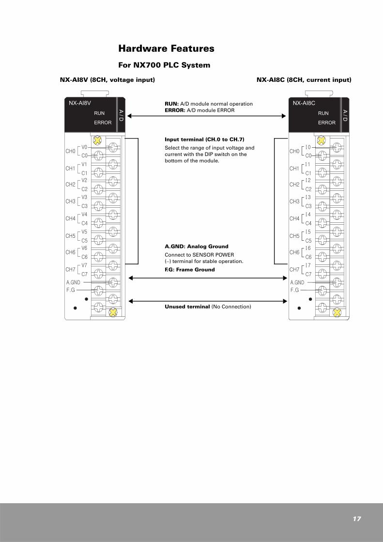
Hardware Features
For NX700 PLC System
NX-AI8V (8CH, voltage input) NX-AI8C (8CH, current input)
RUN: A/D module normal operation ERROR: A/D module ERROR
A.GND: Analog Ground
Connect to SENSOR POWER (−) terminal for stable operation.
F.G: Frame Ground
Input terminal (CH.0 to CH.7)
Select the range of input voltage and current with the DIP switch on the bottom of the module.
Unused terminal (No Connection)
17

18
For NX70 PLC System
NX70-AI8V (8CH, voltage input) NX70-AI8C (8CH, current input)
NX70-AI4V (4CH, voltage input) NX70-AI4C (4CH, current input)
RUN
ERROR
V0C0
C H .0
A/D
NX70-AI8V
V1C1
C H .1
V2
C2C H .2
V3C3
C H .3
A.G ND
F.G
V4C4
C H .4
V5C5
C H .5
V6
C6C H .6
V7C7
C H .7
RUN
ERROR
I0C0
C H .0
A/D
NX70-AI8C
I1
C1C H .1
I2
C2C H .2
C3C H .3
A.G ND
F.G
I3
I4C4
C H .4
I5
C5C H .5
I6
C6C H .6
C7C H .7
I7
RUN: A/D module normal operation ERROR: A/D module error
A.GND: Analog Ground
Connect to the (-) terminal of sensor power for stable operation.
F.G: Frame Ground
Input terminal (CH.0 to CH.7)
Select the range of input voltage and current with the DIP switch on the bottom of the module.
Unused terminal (No Connection)
RUN: A/D module normal operation ERROR: A/D module ERROR
A.GND: Analog Ground
Connect to the (-) terminal of sensor power for stable operation.
F.G: Frame Ground
Input terminal (CH.0 to CH.3)
Select the range of input voltage and current with the DIP switch on the bottom of the module.
Unused terminal (No Connection)
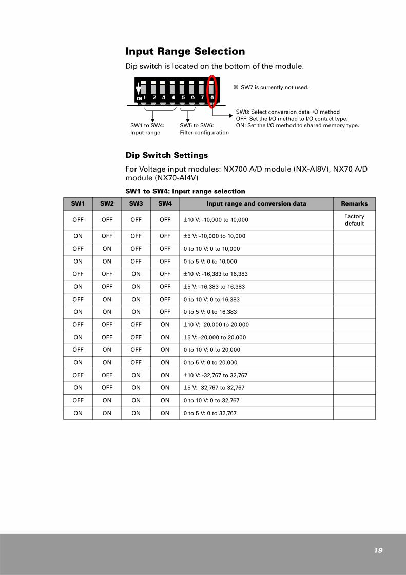
Input Range SelectionDip switch is located on the bottom of the module.
Dip Switch Settings
For Voltage input modules: NX700 A/D module (NX-AI8V), NX70 A/D module (NX70-AI4V)
SW1 to SW4: Input range selection
※ SW7 is currently not used.
SW1 to SW4: Input range
SW5 to SW6: Filter configuration
SW8: Select conversion data I/O method OFF: Set the I/O method to I/O contact type. ON: Set the I/O method to shared memory type.
SW1 SW2 SW3 SW4 Input range and conversion data Remarks
OFF OFF OFF OFF ±10 V: -10,000 to 10,000Factory default
ON OFF OFF OFF ±5 V: -10,000 to 10,000
OFF ON OFF OFF 0 to 10 V: 0 to 10,000
ON ON OFF OFF 0 to 5 V: 0 to 10,000
OFF OFF ON OFF ±10 V: -16,383 to 16,383
ON OFF ON OFF ±5 V: -16,383 to 16,383
OFF ON ON OFF 0 to 10 V: 0 to 16,383
ON ON ON OFF 0 to 5 V: 0 to 16,383
OFF OFF OFF ON ±10 V: -20,000 to 20,000
ON OFF OFF ON ±5 V: -20,000 to 20,000
OFF ON OFF ON 0 to 10 V: 0 to 20,000
ON ON OFF ON 0 to 5 V: 0 to 20,000
OFF OFF ON ON ±10 V: -32,767 to 32,767
ON OFF ON ON ±5 V: -32,767 to 32,767
OFF ON ON ON 0 to 10 V: 0 to 32,767
ON ON ON ON 0 to 5 V: 0 to 32,767
19
20
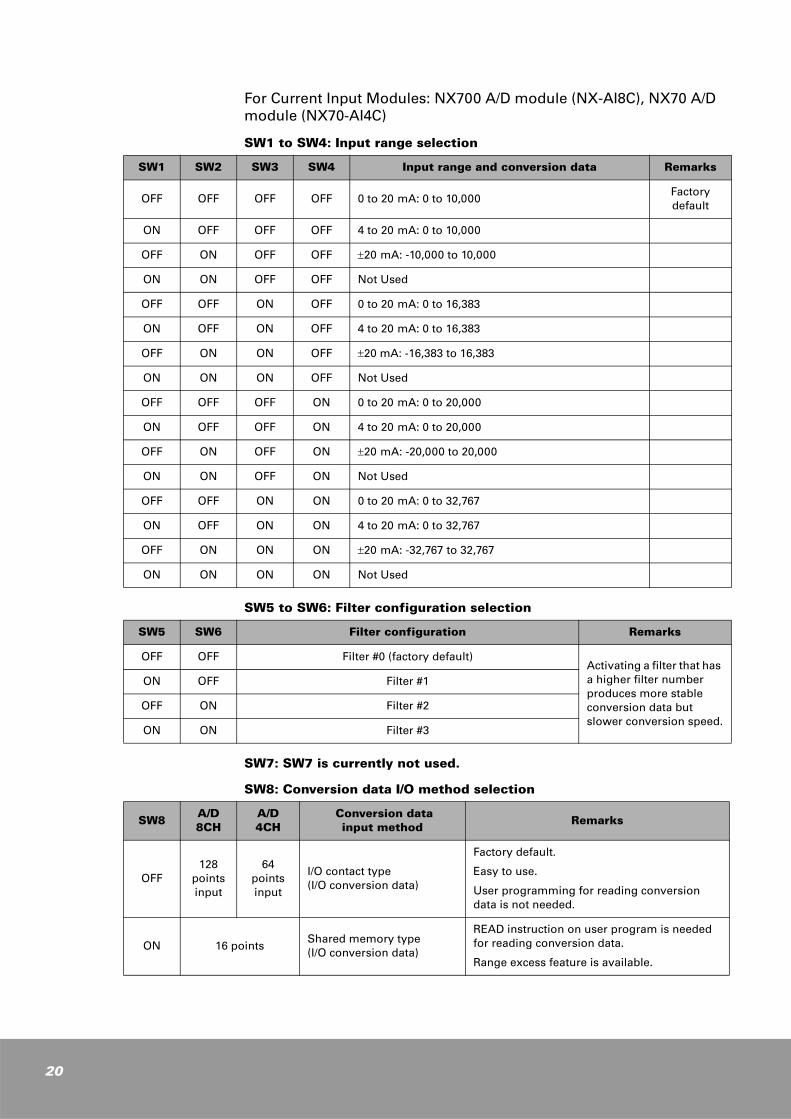
For Current Input Modules: NX700 A/D module (NX-AI8C), NX70 A/D module (NX70-AI4C)
SW1 to SW4: Input range selection
SW5 to SW6: Filter configuration selection
SW7: SW7 is currently not used.
SW8: Conversion data I/O method selection
SW1 SW2 SW3 SW4 Input range and conversion data Remarks
OFF OFF OFF OFF 0 to 20 mA: 0 to 10,000Factory default
ON OFF OFF OFF 4 to 20 mA: 0 to 10,000
OFF ON OFF OFF ±20 mA: -10,000 to 10,000
ON ON OFF OFF Not Used
OFF OFF ON OFF 0 to 20 mA: 0 to 16,383
ON OFF ON OFF 4 to 20 mA: 0 to 16,383
OFF ON ON OFF ±20 mA: -16,383 to 16,383
ON ON ON OFF Not Used
OFF OFF OFF ON 0 to 20 mA: 0 to 20,000
ON OFF OFF ON 4 to 20 mA: 0 to 20,000
OFF ON OFF ON ±20 mA: -20,000 to 20,000
ON ON OFF ON Not Used
OFF OFF ON ON 0 to 20 mA: 0 to 32,767
ON OFF ON ON 4 to 20 mA: 0 to 32,767
OFF ON ON ON ±20 mA: -32,767 to 32,767
ON ON ON ON Not Used
SW5 SW6 Filter configuration Remarks
OFF OFF Filter #0 (factory default)Activating a filter that has a higher filter number produces more stable conversion data but slower conversion speed.
ON OFF Filter #1
OFF ON Filter #2
ON ON Filter #3
SW8A/D 8CH
A/D 4CH
Conversion data input method Remarks
OFF128
points input
64 points input
I/O contact type(I/O conversion data)
Factory default.
Easy to use.
User programming for reading conversion data is not needed.
ON 16 points Shared memory type(I/O conversion data)
READ instruction on user program is needed for reading conversion data.
Range excess feature is available.
I/O Method for CPU ModuleSW8 setting determines how the CPU module handles conversion data from A/D module.
When SW8 is set to OFF, as many words of input contacts as the channels are allocated and the CPU module updates these input contacts every scan, which allows you to read conversion data of A/D modules from these input contacts.
When SW8 is set to ON, only 1-word input contact is allocated and conversion data are stored in shared memory. You should use the READ instruction to read conversion data of A/D modules stored in this shared memory. The 1-word input contact allocated is used as out-of-range flags that indicate whether the conversion data of A/D modules exceed the range or not.
I/O Contact Type (SW8, OFF)
Data conversion method is set to I/O contact type. (SW8 is set to OFF.)
k When an A/D module is mounted onto the first I/O slot (slot 0) and SW8 is set to OFF (I/O contact type), 4-word (64 points) input contacts are allocated for 4-channel A/D module and 8-word (128 points) for 8-channel A/D module.
For 8-channel A/D module (NX700: NX-AI8V, NX-AI8C) (NX70 : NX70-AI8V, NX70-AI8C)
1. NX-series: 8 words (128 points input): WX0 (Ch0), WX1 (Ch1), WX2 (Ch2), .........WX7 (Ch7)
2. NX-plus series: 8 words (128 points input): R0 (Ch0), R1 (Ch1), R2 (Ch2), .......R7 (Ch7)
For 4-channel A/D module (NX70: NX70-AI4V, NX70-AI4C)
1. NX-series: 4 words (64 points input): WX0 (Ch0), WX1 (Ch1), WX2 (Ch2), WX3 (Ch3)
2. NX-plus series: 4 words (64 points input): R0 (Ch0), R1 (Ch1), R2 (Ch2), R3 (Ch3)
k If the data conversion method is set to I/O contact type, many input contacts are used but you need not to use the READ (or RMRD) instruction to read A/D conversion data because the CPU module automatically updates them every scan. Therefore, no additional programming is required to read A/D conversion data.
21
22
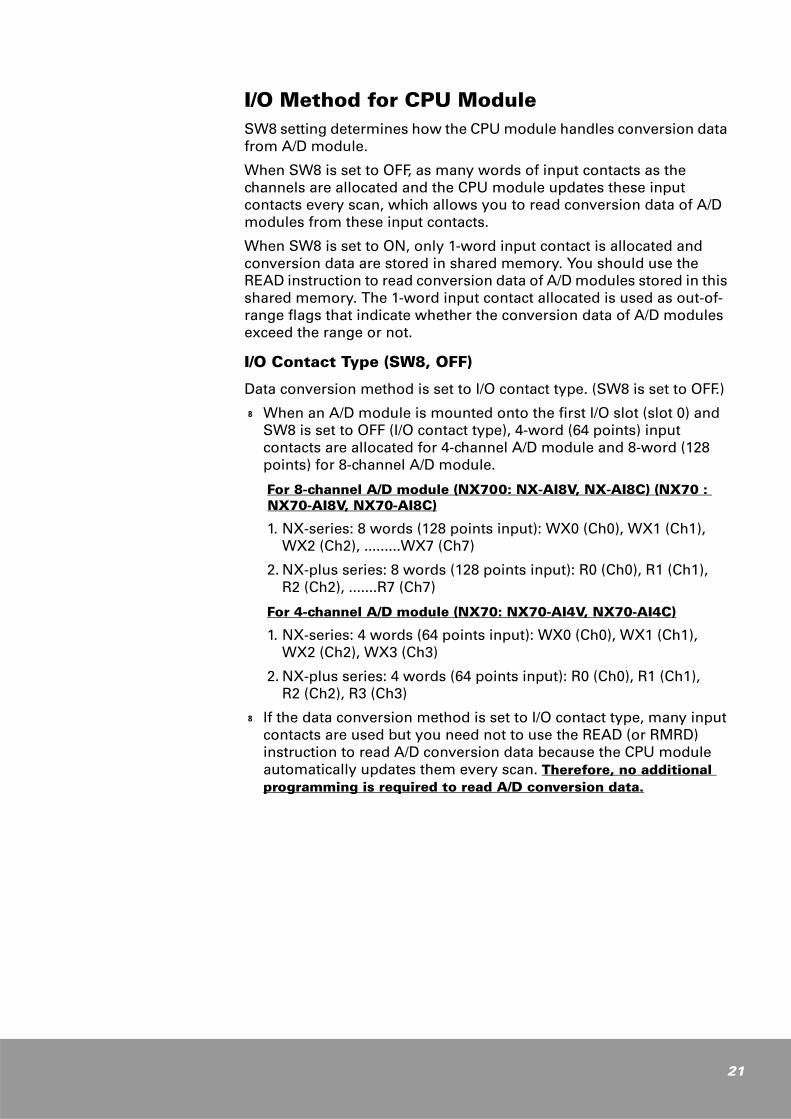
Shared Memory Type (SW8, ON)
Data conversion method is set to shared memory type. (SW8 is set to ON.)
k When an A/D module is mounted onto the first I/O slot (slot 0) and SW8 is set to ON (Shared memory type), 1-word (16 points) input contacts are allocated regardless the number of A/D modules mounted, and the conversion data is stored in the shared memory. See "Shared Memory Usage for A/D Conversion Module" in Chapter 2. You have to use the READ (or RMRD) instruction in your program to read the conversion data stored in shared memory.
k The 16 input contacts allocated are used as out-of-range flags for conversion data. They will be set as shown in the table below.
1. N-series: 1-word input contact (16SX, 16 points input with shared memory)
2. N-plus series: 1-word input contact
k If data conversion method is set to shared memory type, only 16 points are allocated for A/D modules regardless of the number of A/D modules mounted. In addition, many features designed for shared memory are available.
When A/D module is inserted in slot 0: Values in ( ) are applicable to N-plus series
Input signal (Bit contact)
Event Remarks
X0 (R0.0) ON when CH0 range is exceeded
X1 (R0.1) ON when CH1 range is exceeded
X2 (R0.2) ON when CH2 range is exceeded
X3 (R0.3) ON when CH3 range is exceeded
… ……………
X7 (R0.7) ON when CH7 range is exceeded
The out-of-range flag is set to ON in the case of no wiring or current of about 3.987mA or less.
NOTE
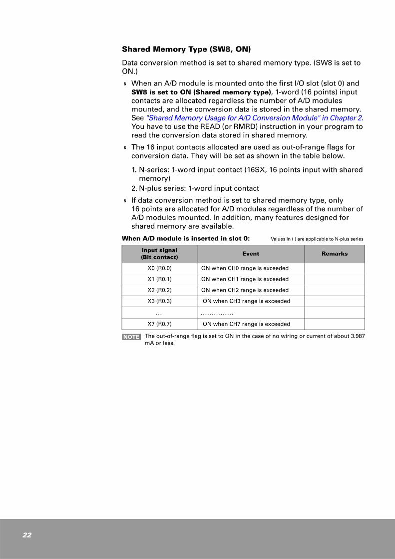
I/O Conversion Characteristics
Voltage Input Module (NX-AI8V, NX70-AI8V, NX70-AI4V)
-10 to 10 V
32,767
16,383
-16,383
-32,767
0
0-5 V-10 V
+5 V +10 V
Conversion data
Input voltage
※ Set the input range with the setting switches, SW1 to SW4.
SW3, SW4: ON, ON (±10 V, -32767 to 32767)
Conversion data
-10 V = -32,767 -5 V = -16,383 0 V = 0+5 V = 16,383+10 V = 32,767
0 to 5 V
32,767
16,383
0
0-5 V
+2.5 V +5 V
Conversion data
Input voltage
※ Set the input range with the setting switches, SW1 to SW4.
SW1 to SW4: ON (0 to 5 V, 0 to 32767)
Conversion data
0 V = 0 2.5 V= 16,383 5 V = 32,767
ON 1 2 3 4 5 6 7 8
23
24
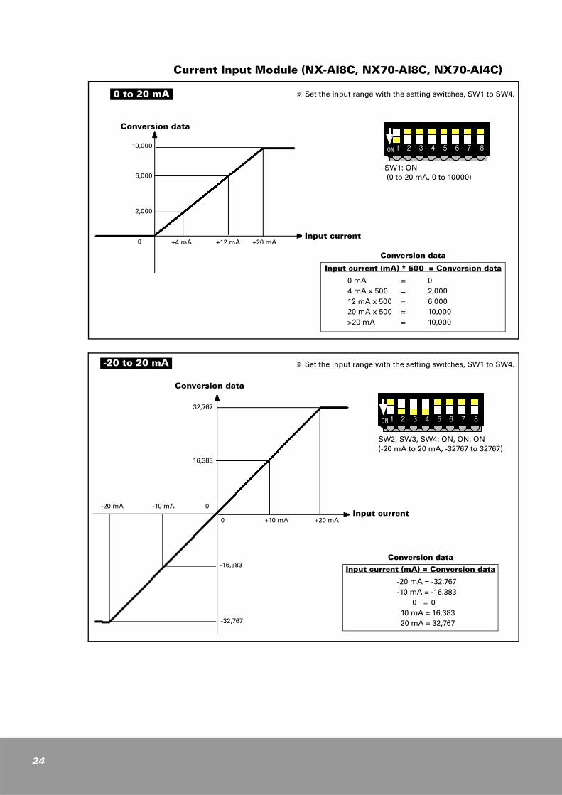
Current Input Module (NX-AI8C, NX70-AI8C, NX70-AI4C)
0 to 20 mA
10,000
6,000
+4 mA0
Conversion data
Input current
※ Set the input range with the setting switches, SW1 to SW4.
SW1: ON (0 to 20 mA, 0 to 10000)
Conversion data
Input current (mA) * 500 = Conversion data
0 mA = 04 mA x 500 = 2,00012 mA x 500 = 6,00020 mA x 500 = 10,000>20 mA = 10,000
2,000
+12 mA +20 mA
ON 1 2 3 4 5 6 7 8
32,767
16,383
-16,383
-32,767
0
0-10 mA-20 mA
+10 mA +20 mA
Conversion data
Input current
-20 to 20 mA ※ Set the input range with the setting switches, SW1 to SW4.
SW2, SW3, SW4: ON, ON, ON (-20 mA to 20 mA, -32767 to 32767)
Conversion data
Input current (mA) = Conversion data
-20 mA = -32,767 -10 mA = -16.383
0 = 0 10 mA = 16,383 20 mA = 32,767
ON 1 2 3 4 5 6 7 8
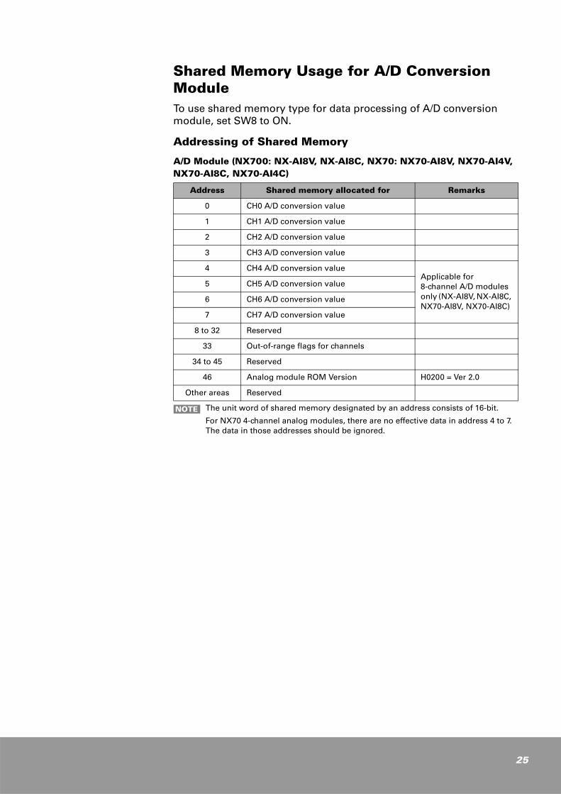
Shared Memory Usage for A/D Conversion ModuleTo use shared memory type for data processing of A/D conversion module, set SW8 to ON.
Addressing of Shared Memory
A/D Module (NX700: NX-AI8V, NX-AI8C, NX70: NX70-AI8V, NX70-AI4V, NX70-AI8C, NX70-AI4C)
Address Shared memory allocated for Remarks
0 CH0 A/D conversion value
1 CH1 A/D conversion value
2 CH2 A/D conversion value
3 CH3 A/D conversion value
4 CH4 A/D conversion valueApplicable for 8-channel A/D modules only (NX-AI8V, NX-AI8C, NX70-AI8V, NX70-AI8C)
5 CH5 A/D conversion value
6 CH6 A/D conversion value
7 CH7 A/D conversion value
8 to 32 Reserved
33 Out-of-range flags for channels
34 to 45 Reserved
46 Analog module ROM Version H0200 = Ver 2.0
Other areas Reserved
The unit word of shared memory designated by an address consists of 16-bit.
For NX70 4-channel analog modules, there are no effective data in address 4 to 7. The data in those addresses should be ignored.
NOTE
25
26
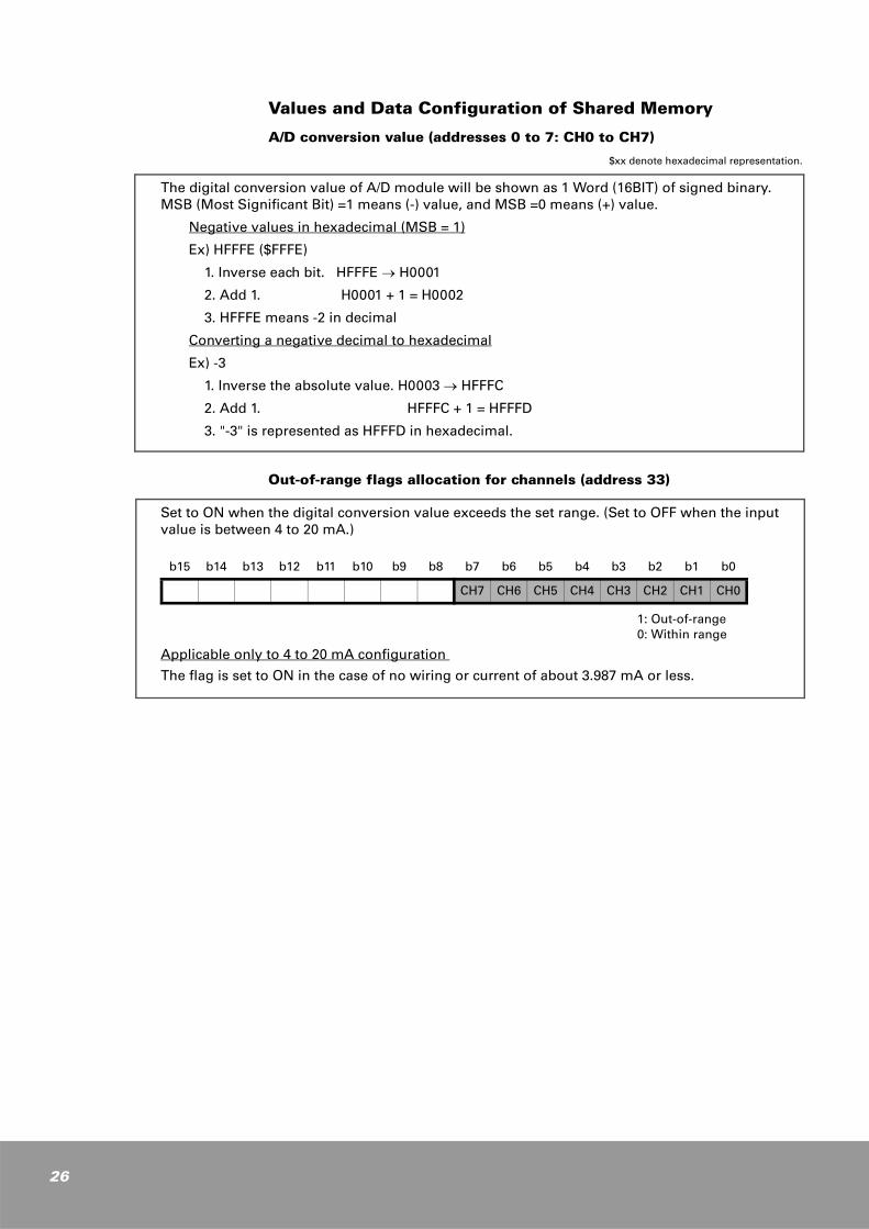
Values and Data Configuration of Shared Memory
A/D conversion value (addresses 0 to 7: CH0 to CH7)
$xx denote hexadecimal representation.
The digital conversion value of A/D module will be shown as 1 Word (16BIT) of signed binary. MSB (Most Significant Bit) =1 means (-) value, and MSB =0 means (+) value.
Negative values in hexadecimal (MSB = 1)
Ex) HFFFE ($FFFE)
1. Inverse each bit. HFFFE → H0001
2. Add 1. H0001 + 1 = H0002
3. HFFFE means -2 in decimal
Converting a negative decimal to hexadecimal
Ex) -3
1. Inverse the absolute value. H0003 → HFFFC
2. Add 1. HFFFC + 1 = HFFFD
3. "-3" is represented as HFFFD in hexadecimal.
Out-of-range flags allocation for channels (address 33)
Set to ON when the digital conversion value exceeds the set range. (Set to OFF when the input value is between 4 to 20 mA.)
Applicable only to 4 to 20 mA configuration
The flag is set to ON in the case of no wiring or current of about 3.987 mA or less.
1: Out-of-range0: Within range
b15 b14 b13 b12 b11 b10 b9 b8 b7 b6 b5 b4 b3 b2 b1 b0
CH7 CH6 CH5 CH4 CH3 CH2 CH1 CH0
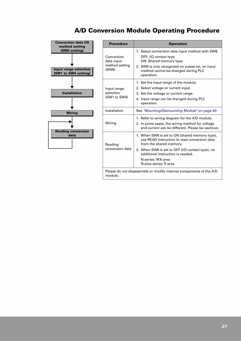
A/D Conversion Module Operating Procedure
Conversion data I/O method setting(SW8 setting)
Input range selection(SW1 to SW4 setting)
Installation
Wiring
Reading conversion data
Procedure Operation
Conversion data input method setting (SW8)
1. Select conversion data input method with SW8.
OFF: I/O contact typeON: Shared memory type
2. SW8 is only recognized on power-on, so input method cannot be changed during PLC operation.
Input range selection (SW1 to SW4)
1. Set the input range of the module.
2. Select voltage or current input.
3. Set the voltage or current range.
4. Input range can be changed during PLC operation.
Installation See "Mounting/Dismounting Module" on page 93.
Wiring1. Refer to wiring diagram for the A/D module.
2. In some cases, the wiring method for voltage and current can be different. Please be cautious.
Reading conversion data
1. When SW8 is set to ON (shared memory type), use READ instruction to read conversion data from the shared memory.
2. When SW8 is set to OFF (I/O contact type), no additional instruction is needed.
N-series: WX area N-plus series: R area
Please do not disassemble or modify internal components of the A/D module.
27
28
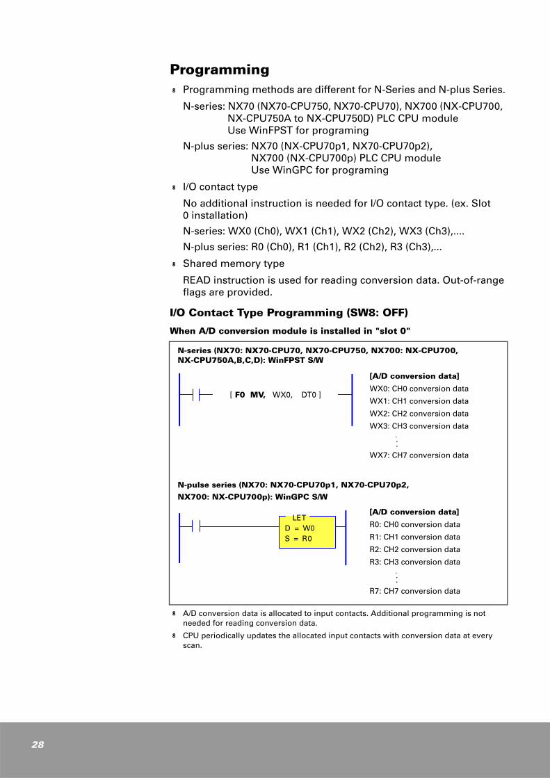
Programmingk Programming methods are different for N-Series and N-plus Series.
N-series: NX70 (NX70-CPU750, NX70-CPU70), NX700 (NX-CPU700, NX-CPU750A to NX-CPU750D) PLC CPU module Use WinFPST for programing
N-plus series: NX70 (NX-CPU70p1, NX70-CPU70p2), NX700 (NX-CPU700p) PLC CPU module Use WinGPC for programing
k I/O contact type
No additional instruction is needed for I/O contact type. (ex. Slot 0 installation)
N-series: WX0 (Ch0), WX1 (Ch1), WX2 (Ch2), WX3 (Ch3),....
N-plus series: R0 (Ch0), R1 (Ch1), R2 (Ch2), R3 (Ch3),...
k Shared memory type
READ instruction is used for reading conversion data. Out-of-range flags are provided.
I/O Contact Type Programming (SW8: OFF)
When A/D conversion module is installed in "slot 0"
N-series (NX70: NX70-CPU70, NX70-CPU750, NX700: NX-CPU700, NX-CPU750A,B,C,D): WinFPST S/W
N-pulse series (NX70: NX70-CPU70p1, NX70-CPU70p2, NX700: NX-CPU700p): WinGPC S/W
k A/D conversion data is allocated to input contacts. Additional programming is not needed for reading conversion data.
k CPU periodically updates the allocated input contacts with conversion data at every scan.
[ F0 MV, WX0, DT0 ]
[A/D conversion data]
WX0: CH0 conversion data
WX1: CH1 conversion data
WX2: CH2 conversion data
WX3: CH3 conversion data ...
WX7: CH7 conversion data
[A/D conversion data]
R0: CH0 conversion data
R1: CH1 conversion data
R2: CH2 conversion data
R3: CH3 conversion data ...
R7: CH7 conversion data
LETD = W0S = R0
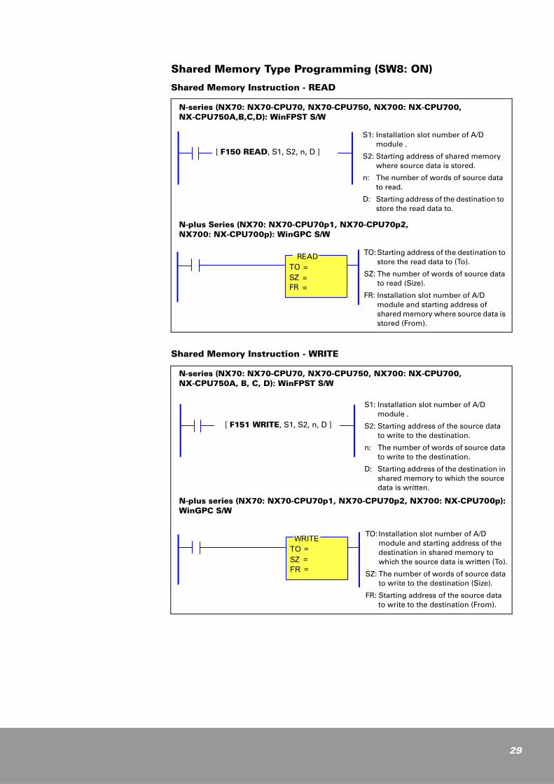
Shared Memory Type Programming (SW8: ON)
Shared Memory Instruction - READ
N-series (NX70: NX70-CPU70, NX70-CPU750, NX700: NX-CPU700, NX-CPU750A,B,C,D): WinFPST S/W
N-plus Series (NX70: NX70-CPU70p1, NX70-CPU70p2, NX700: NX-CPU700p): WinGPC S/W
Shared Memory Instruction - WRITE
N-series (NX70: NX70-CPU70, NX70-CPU750, NX700: NX-CPU700, NX-CPU750A, B, C, D): WinFPST S/W
N-plus series (NX70: NX70-CPU70p1, NX70-CPU70p2, NX700: NX-CPU700p): WinGPC S/W
[ F150 READ, S1, S2, n, D ]
S1: Installation slot number of A/D module .
S2: Starting address of shared memory where source data is stored.
n: The number of words of source data to read.
D: Starting address of the destination to store the read data to.
TO: Starting address of the destination to store the read data to (To).
SZ: The number of words of source data to read (Size).
FR: Installation slot number of A/D module and starting address of shared memory where source data is stored (From).
READTO =SZ =FR =
[ F151 WRITE, S1, S2, n, D ]
S1: Installation slot number of A/D module .
S2: Starting address of the source data to write to the destination.
n: The number of words of source data to write to the destination.
D: Starting address of the destination in shared memory to which the source data is written.
TO: Installation slot number of A/D module and starting address of the destination in shared memory to which the source data is written (To).
SZ: The number of words of source data to write to the destination (Size).
FR: Starting address of the source data to write to the destination (From).
WRITETO =SZ =FR =
29
30
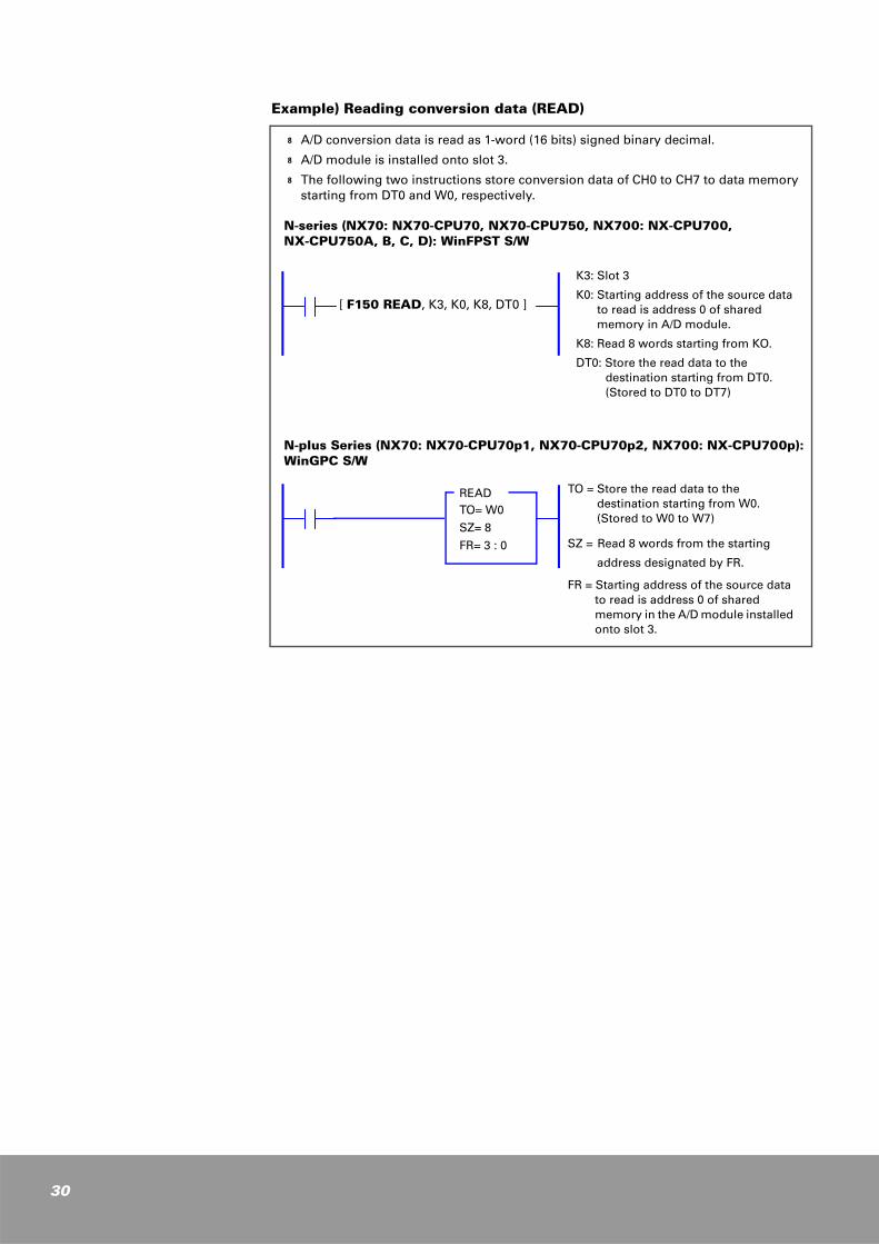
Example) Reading conversion data (READ)
k A/D conversion data is read as 1-word (16 bits) signed binary decimal.
k A/D module is installed onto slot 3.
k The following two instructions store conversion data of CH0 to CH7 to data memory starting from DT0 and W0, respectively.
N-series (NX70: NX70-CPU70, NX70-CPU750, NX700: NX-CPU700, NX-CPU750A, B, C, D): WinFPST S/W
N-plus Series (NX70: NX70-CPU70p1, NX70-CPU70p2, NX700: NX-CPU700p): WinGPC S/W
[ F150 READ, K3, K0, K8, DT0 ]
K3: Slot 3
K0: Starting address of the source data to read is address 0 of shared memory in A/D module.
K8: Read 8 words starting from KO.
DT0: Store the read data to the destination starting from DT0.(Stored to DT0 to DT7)
TO = Store the read data to the destination starting from W0. (Stored to W0 to W7)
SZ = Read 8 words from the starting
address designated by FR.
FR = Starting address of the source data to read is address 0 of shared memory in the A/D module installed onto slot 3.
READTO= W0
SZ= 8
FR= 3 : 0
3
D/A Conversion Module
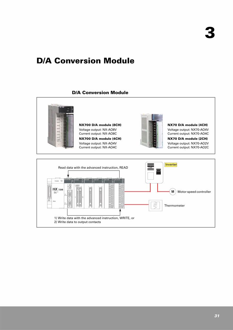
D/A Conversion Module
NX700 D/A module (8CH)Voltage output: NX-AO8V Current output: NX-AO8C
NX700 D/A module (4CH)Voltage output: NX-AO4V Current output: NX-AO4C
NX70 D/A module (4CH) Voltage output: NX70-AO4V Current output: NX70-AO4C
NX70 D/A module (2CH) Voltage output: NX70-AO2V Current output: NX70-AO2C
Read data with the advanced instruction, READ
1) Write data with the advanced instruction, WRITE, or2) Write data to output contacts
Inverter
Motor speed controller
Thermometer
31
32
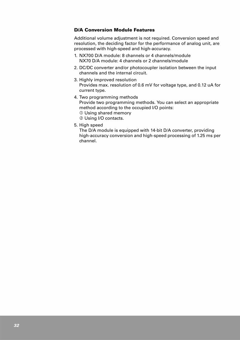
D/A Conversion Module Features
Additional volume adjustment is not required. Conversion speed and resolution, the deciding factor for the performance of analog unit, are processed with high-speed and high-accuracy.
1. NX700 D/A module: 8 channels or 4 channels/moduleNX70 D/A module: 4 channels or 2 channels/module
2. DC/DC converter and/or photocoupler isolation between the input channels and the internal circuit.
3. Highly improved resolutionProvides max. resolution of 0.6 mV for voltage type, and 0.12 uA for current type.
4. Two programming methods Provide two programming methods. You can select an appropriate method according to the occupied I/O points:
Using shared memory Using I/O contacts.
5. High speedThe D/A module is equipped with 14-bit D/A converter, providing high-accuracy conversion and high-speed processing of 1.25 ms per channel.
D/A Conversion Module Specifications
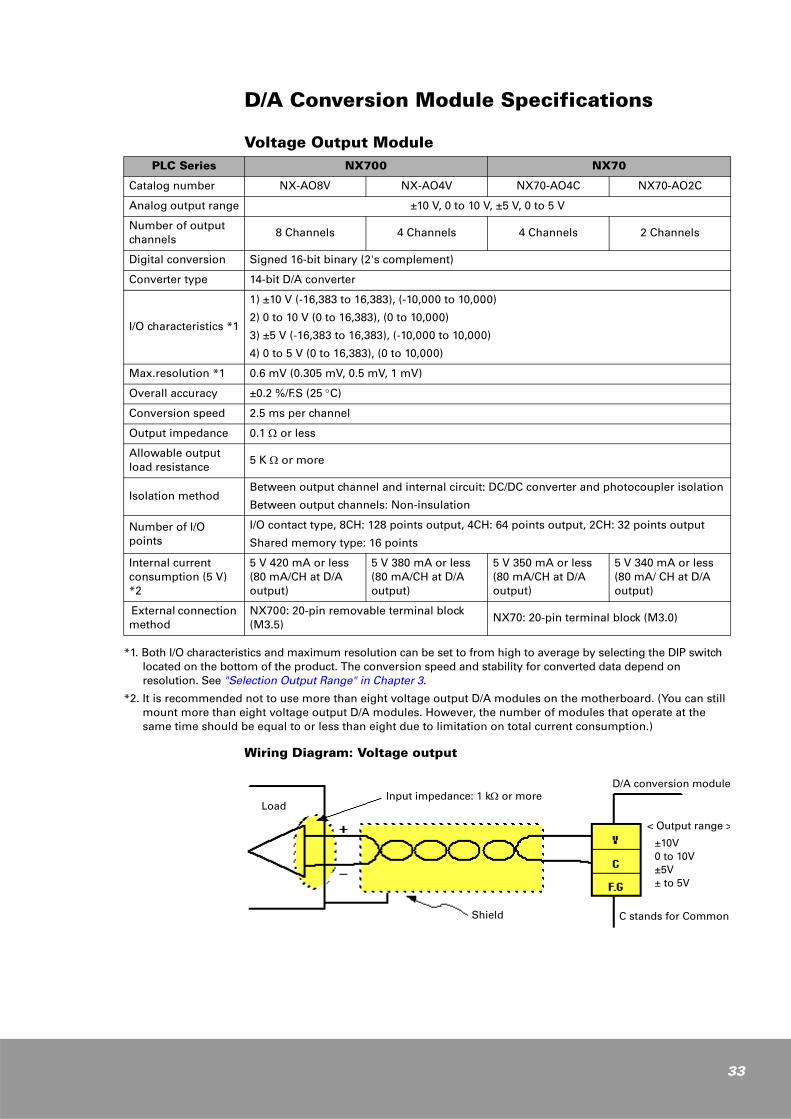
Voltage Output Module
*1. Both I/O characteristics and maximum resolution can be set to from high to average by selecting the DIP switch located on the bottom of the product. The conversion speed and stability for converted data depend on resolution. See "Selection Output Range" in Chapter 3.
*2. It is recommended not to use more than eight voltage output D/A modules on the motherboard. (You can still mount more than eight voltage output D/A modules. However, the number of modules that operate at the same time should be equal to or less than eight due to limitation on total current consumption.)
Wiring Diagram: Voltage output
PLC Series NX700 NX70
Catalog number NX-AO8V NX-AO4V NX70-AO4C NX70-AO2C
Analog output range ±10 V, 0 to 10 V, ±5 V, 0 to 5 V
Number of output channels
8 Channels 4 Channels 4 Channels 2 Channels
Digital conversion Signed 16-bit binary (2's complement)
Converter type 14-bit D/A converter
I/O characteristics *1
1) ±10 V (-16,383 to 16,383), (-10,000 to 10,000)
2) 0 to 10 V (0 to 16,383), (0 to 10,000)
3) ±5 V (-16,383 to 16,383), (-10,000 to 10,000)
4) 0 to 5 V (0 to 16,383), (0 to 10,000)
Max.resolution *1 0.6 mV (0.305 mV, 0.5 mV, 1 mV)
Overall accuracy ±0.2 %/F.S (25 °C)
Conversion speed 2.5 ms per channel
Output impedance 0.1 Ω or less
Allowable output load resistance
5 K Ω or more
Isolation methodBetween output channel and internal circuit: DC/DC converter and photocoupler isolation
Between output channels: Non-insulation
Number of I/O points
I/O contact type, 8CH: 128 points output, 4CH: 64 points output, 2CH: 32 points output
Shared memory type: 16 points
Internal current consumption (5 V) *2
5 V 420 mA or less(80 mA/CH at D/A output)
5 V 380 mA or less(80 mA/CH at D/A output)
5 V 350 mA or less (80 mA/CH at D/A output)
5 V 340 mA or less(80 mA/ CH at D/A output)
External connection method
NX700: 20-pin removable terminal block (M3.5)
NX70: 20-pin terminal block (M3.0)
Input impedance: 1 kΩ or moreLoad
Shield
D/A conversion module
< Output range >
±10V0 to 10V±5V± to 5V
C stands for Common
33
34
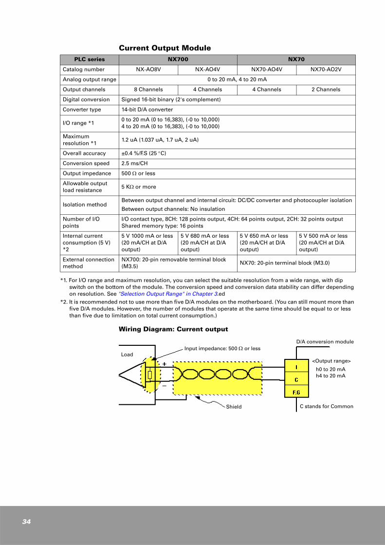
Current Output Module
*1. For I/O range and maximum resolution, you can select the suitable resolution from a wide range, with dip switch on the bottom of the module. The conversion speed and conversion data stability can differ depending on resolution. See "Selection Output Range" in Chapter 3.ed
*2. It is recommended not to use more than five D/A modules on the motherboard. (You can still mount more than five D/A modules. However, the number of modules that operate at the same time should be equal to or less than five due to limitation on total current consumption.)
Wiring Diagram: Current output
PLC series NX700 NX70
Catalog number NX-AO8V NX-AO4V NX70-AO4V NX70-AO2V
Analog output range 0 to 20 mA, 4 to 20 mA
Output channels 8 Channels 4 Channels 4 Channels 2 Channels
Digital conversion Signed 16-bit binary (2's complement)
Converter type 14-bit D/A converter
I/O range *10 to 20 mA (0 to 16,383), (-0 to 10,000)4 to 20 mA (0 to 16,383), (-0 to 10,000)
Maximum resolution *1
1.2 uA (1.037 uA, 1.7 uA, 2 uA)
Overall accuracy ±0.4 %/F.S (25 °C)
Conversion speed 2.5 ms/CH
Output impedance 500 Ω or less
Allowable output load resistance
5 KΩ or more
Isolation methodBetween output channel and internal circuit: DC/DC converter and photocoupler isolation
Between output channels: No insulation
Number of I/O points
I/O contact type, 8CH: 128 points output, 4CH: 64 points output, 2CH: 32 points output Shared memory type: 16 points
Internal current consumption (5 V) *2
5 V 1000 mA or less(20 mA/CH at D/A output)
5 V 680 mA or less(20 mA/CH at D/A output)
5 V 650 mA or less (20 mA/CH at D/A output)
5 V 500 mA or less(20 mA/CH at D/A output)
External connection method
NX700: 20-pin removable terminal block (M3.5)
NX70: 20-pin terminal block (M3.0)
Input impedance: 500 Ω or lessLoad
Shield
D/A conversion module
<Output range>
h0 to 20 mAh4 to 20 mA
C stands for Common
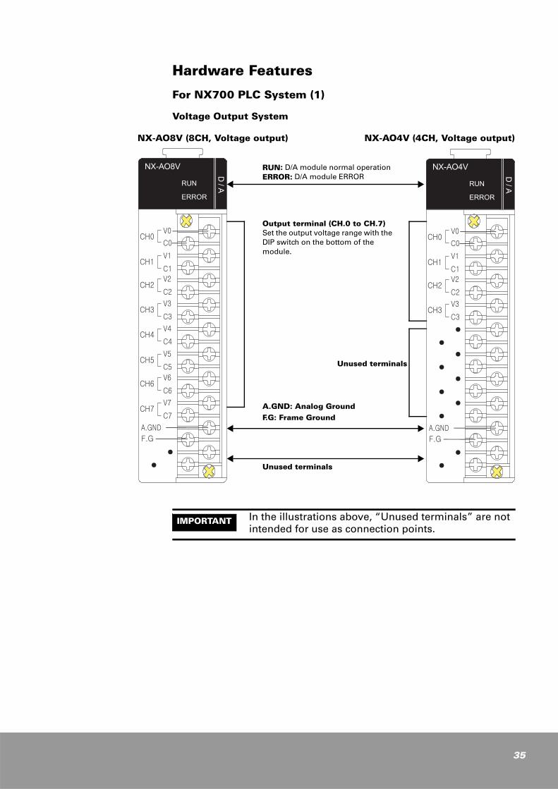
Hardware Features
For NX700 PLC System (1)
Voltage Output System
RUN: D/A module normal operationERROR: D/A module ERROR
Output terminal (CH.0 to CH.7)Set the output voltage range with the DIP switch on the bottom of the module.
A.GND: Analog GroundF.G: Frame Ground
Unused terminals
NX-AO8V (8CH, Voltage output) NX-AO4V (4CH, Voltage output)
Unused terminals
IMPORTANT In the illustrations above, “Unused terminals” are not intended for use as connection points.
35
36
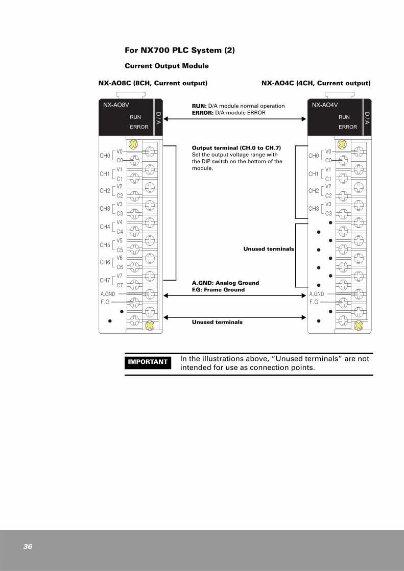
For NX700 PLC System (2)
Current Output Module
IMPORTANT In the illustrations above, “Unused terminals” are not intended for use as connection points.
RUN: D/A module normal operationERROR: D/A module ERROR
Output terminal (CH.0 to CH.7)Set the output voltage range with the DIP switch on the bottom of the module.
A.GND: Analog GroundF.G: Frame Ground
Unused terminals
NX-AO8C (8CH, Current output) NX-AO4C (4CH, Current output)
Unused terminals
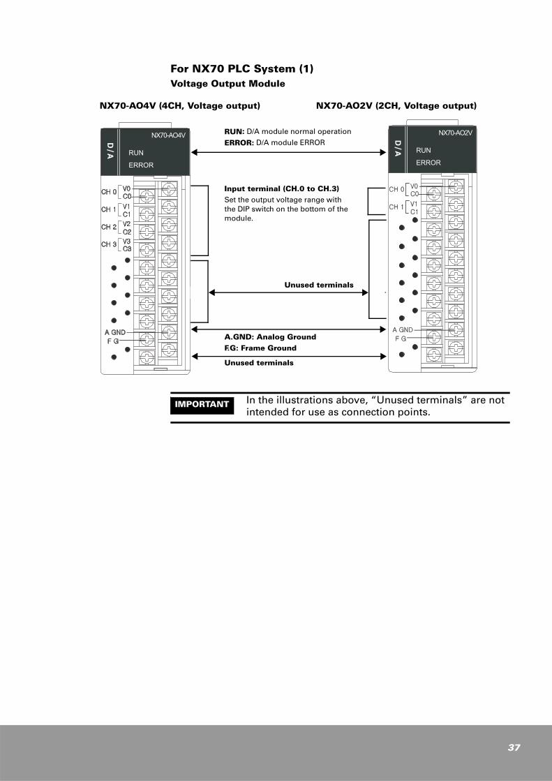
For NX70 PLC System (1)Voltage Output Module
RUN: D/A module normal operation
ERROR: D/A module ERROR
Input terminal (CH.0 to CH.3)Set the output voltage range with the DIP switch on the bottom of the module.
A.GND: Analog GroundF.G: Frame Ground
NX70-AO4V (4CH, Voltage output) NX70-AO2V (2CH, Voltage output)
Unused terminals
Unused terminals
IMPORTANT In the illustrations above, “Unused terminals” are not intended for use as connection points.
37
38
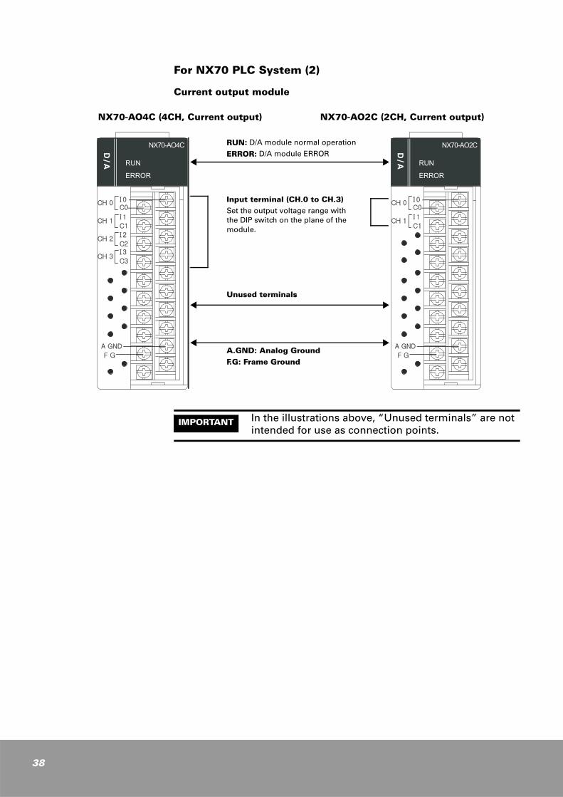
For NX70 PLC System (2)
Current output module
RUN: D/A module normal operation
ERROR: D/A module ERROR
Input terminal (CH.0 to CH.3)Set the output voltage range with the DIP switch on the plane of the module.
A.GND: Analog GroundF.G: Frame Ground
Unused terminals
NX70-AO2C (2CH, Current output)NX70-AO4C (4CH, Current output)
IMPORTANT In the illustrations above, “Unused terminals” are not intended for use as connection points.
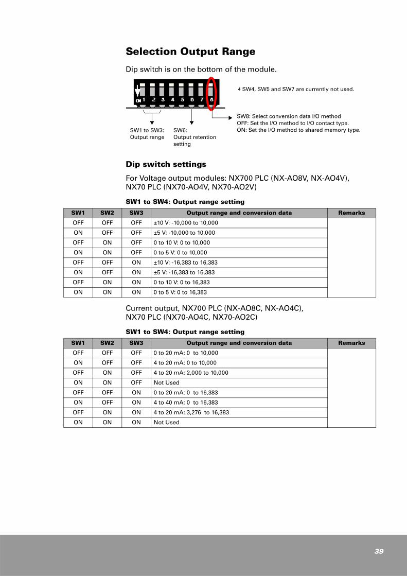
Selection Output Range
Dip switch is on the bottom of the module.
Dip switch settings
For Voltage output modules: NX700 PLC (NX-AO8V, NX-AO4V), NX70 PLC (NX70-AO4V, NX70-AO2V)
SW1 to SW4: Output range setting
Current output, NX700 PLC (NX-AO8C, NX-AO4C), NX70 PLC (NX70-AO4C, NX70-AO2C)
SW1 to SW4: Output range setting
g SW4, SW5 and SW7 are currently not used.
SW1 to SW3:Output range
SW6:Output retention setting
SW8: Select conversion data I/O method OFF: Set the I/O method to I/O contact type. ON: Set the I/O method to shared memory type.
SW1 SW2 SW3 Output range and conversion data Remarks
OFF OFF OFF ±10 V: -10,000 to 10,000
ON OFF OFF ±5 V: -10,000 to 10,000
OFF ON OFF 0 to 10 V: 0 to 10,000
ON ON OFF 0 to 5 V: 0 to 10,000
OFF OFF ON ±10 V: -16,383 to 16,383
ON OFF ON ±5 V: -16,383 to 16,383
OFF ON ON 0 to 10 V: 0 to 16,383
ON ON ON 0 to 5 V: 0 to 16,383
SW1 SW2 SW3 Output range and conversion data Remarks
OFF OFF OFF 0 to 20 mA: 0 to 10,000
ON OFF OFF 4 to 20 mA: 0 to 10,000
OFF ON OFF 4 to 20 mA: 2,000 to 10,000
ON ON OFF Not Used
OFF OFF ON 0 to 20 mA: 0 to 16,383
ON OFF ON 4 to 40 mA: 0 to 16,383
OFF ON ON 4 to 20 mA: 3,276 to 16,383
ON ON ON Not Used
39
40
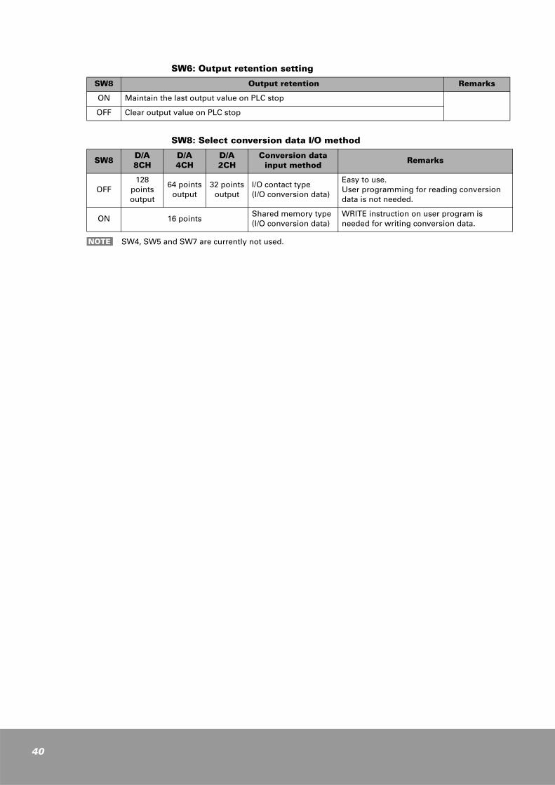
SW6: Output retention setting
SW8: Select conversion data I/O method
SW8 Output retention Remarks
ON Maintain the last output value on PLC stop
OFF Clear output value on PLC stop
SW8D/A 8CH
D/A 4CH
D/A 2CH
Conversion data input method Remarks
OFF128
points output
64 pointsoutput
32 pointsoutput
I/O contact type(I/O conversion data)
Easy to use.User programming for reading conversiondata is not needed.
ON 16 pointsShared memory type (I/O conversion data)
WRITE instruction on user program is needed for writing conversion data.
SW4, SW5 and SW7 are currently not used.NOTE

I/O Method for CPU ModuleSW8 setting determines how the CPU module handles conversion data from D/A module.
When SW8 is set to OFF, as many words of output contacts as the channels are allocated and the CPU module updates these output contacts every scan, which allows you to read conversion data of D/A modules from these input contacts.
When SW8 is set to ON, only 1-word input contact is allocated and conversion data are stored in shared memory. You should use the READ instruction to read conversion data of D/A modules stored in this shared memory. The 1-word input contact allocated is used as out-of-range flags that indicate whether the conversion data of D/A modules exceed the range or not.
I/O Contact Type (SW8, OFF)
Data conversion method is set to I/O contact type. (SW8 is set to OFF.)
k When an D/A module is mounted onto the first I/O slot (slot 0) and SW8 is set to OFF (I/O contact type), 2-word (32 points) output contacts are allocated for 4-channel D/A module and 8-word (128 points) for 8-channel D/A module.
For 2-channel D/A module (NX70: NX70-AO2V, NX70-AO2C)
1. NX-series: 2 words (32 points output): WY0 (Ch0), WY1 (Ch1)
2. NX-plus series: 2 words (32 points output): R0 (Ch0), R1 (Ch1)
For 4-channel D/A module (NX70-AO4V, NX70-AO4C, NX700: NX-AO4V, NX-AO4C))
1. NX-series: 4 words (64 points output): WY0 (Ch0), WY1 (Ch1), WY2 (Ch2), WY3 (Ch3)
2. NX-plus series: 4 words (64 points output): R0 (Ch0), R1 (Ch1), R2 (Ch2), R3 (Ch3)
For 8-channel D/A module (NX700: NX-AO8V, NX-AO8C)
1. NX-series: 8 words (128 points output): WY0 (Ch0), WY1 (Ch1), WY2 (Ch2), ... WY7 (Ch7)
2. NX-plus series: 8 words (128 points output): R0 (Ch0), R1 (Ch1), R2 (Ch2), ... R7 (Ch7)
k If the data conversion method is set to I/O contact type, many output contacts are used but you need not to use the READ (or RMRD) instruction to read D/A conversion data because the CPU module automatically updates them every scan. Therefore, no additional programming is required to read D/A conversion data.
41
42
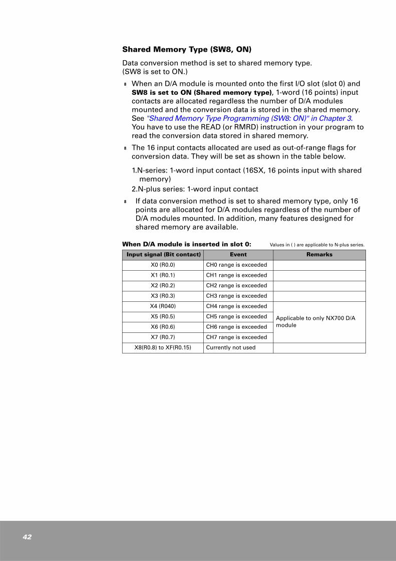
Shared Memory Type (SW8, ON)
Data conversion method is set to shared memory type. (SW8 is set to ON.)
k When an D/A module is mounted onto the first I/O slot (slot 0) and SW8 is set to ON (Shared memory type), 1-word (16 points) input contacts are allocated regardless the number of D/A modules mounted and the conversion data is stored in the shared memory. See "Shared Memory Type Programming (SW8: ON)" in Chapter 3. You have to use the READ (or RMRD) instruction in your program to read the conversion data stored in shared memory.
k The 16 input contacts allocated are used as out-of-range flags for conversion data. They will be set as shown in the table below.
1.N-series: 1-word input contact (16SX, 16 points input with shared memory)
2.N-plus series: 1-word input contact
k If data conversion method is set to shared memory type, only 16 points are allocated for D/A modules regardless of the number of D/A modules mounted. In addition, many features designed for shared memory are available.
When D/A module is inserted in slot 0: Values in ( ) are applicable to N-plus series.
Input signal (Bit contact) Event Remarks
X0 (R0.0) CH0 range is exceeded
X1 (R0.1) CH1 range is exceeded
X2 (R0.2) CH2 range is exceeded
X3 (R0.3) CH3 range is exceeded
X4 (R040) CH4 range is exceeded
Applicable to only NX700 D/A module
X5 (R0.5) CH5 range is exceeded
X6 (R0.6) CH6 range is exceeded
X7 (R0.7) CH7 range is exceeded
X8(R0.8) to XF(R0.15) Currently not used
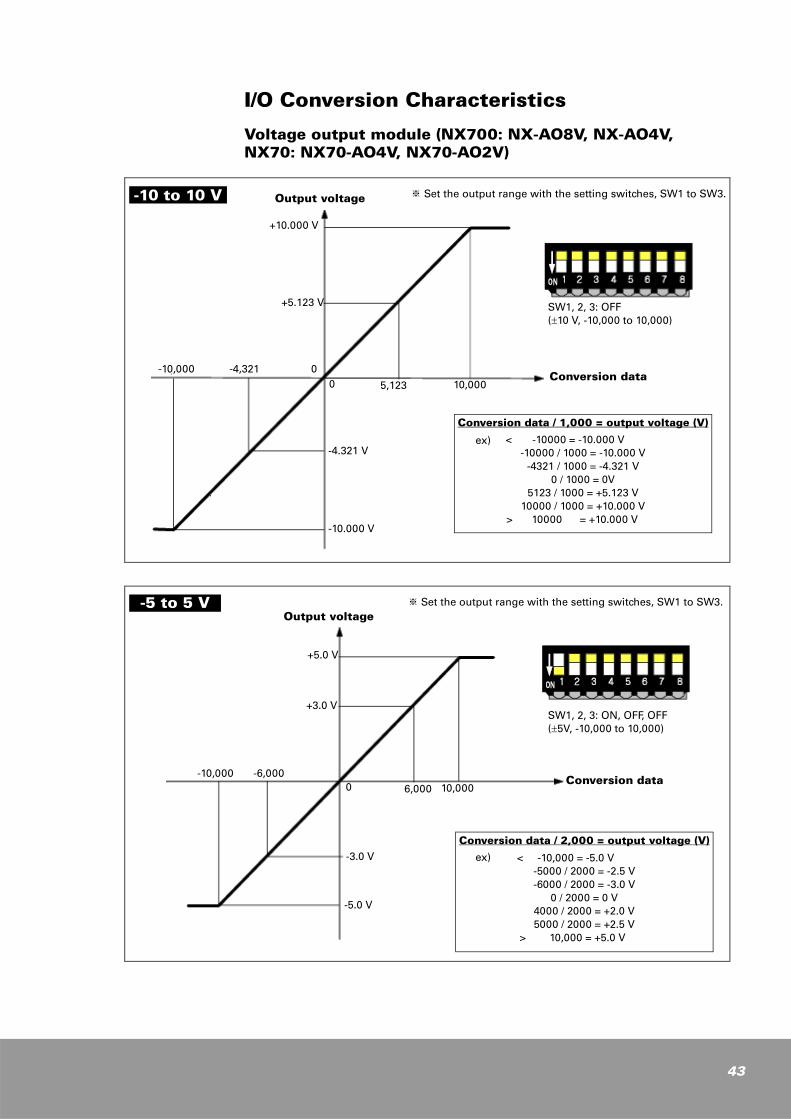
I/O Conversion Characteristics
Voltage output module (NX700: NX-AO8V, NX-AO4V, NX70: NX70-AO4V, NX70-AO2V)
Output voltage ※ Set the output range with the setting switches, SW1 to SW3.
SW1, 2, 3: OFF(±10 V, -10,000 to 10,000)
Conversion data
Conversion data / 1,000 = output voltage (V)
< -10000 = -10.000 V-10000 / 1000 = -10.000 V
-4321 / 1000 = -4.321 V0 / 1000 = 0V
5123 / 1000 = +5.123 V10000 / 1000 = +10.000 V
> 10000 = +10.000 V
-10 to 10 V
ex)
-10,000 -4,321 00 5,123 10,000
-4.321 V
-10.000 V
+10.000 V
+5.123 V
Output voltage※ Set the output range with the setting switches, SW1 to SW3.
SW1, 2, 3: ON, OFF, OFF(±5V, -10,000 to 10,000)
Conversion data
Conversion data / 2,000 = output voltage (V)
< -10,000 = -5.0 V-5000 / 2000 = -2.5 V-6000 / 2000 = -3.0 V
0 / 2000 = 0 V 4000 / 2000 = +2.0 V5000 / 2000 = +2.5 V
> 10,000 = +5.0 V
-5 to 5 V
ex)
0
-3.0 V
-5.0 V
+5.0 V
+3.0 V
-10,000 -6,0006,000 10,000
43
44
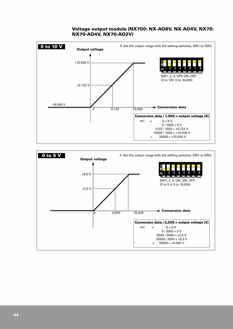
Voltage output module (NX700: NX-AO8V, NX-AO4V, NX70: NX70-AO4V, NX70-AO2V)
Output voltage
SW1, 2, 3: OFF, ON, OFF(0 to 10V, 0 to 10,000)
Conversion data
Conversion data / 1,000 = output voltage (V)
< 0 = 0 V0 / 1000 = 0 V
5123 / 1000 = +5.123 V10000 / 1000 = +10.000 V
> 10000 = +10.000 V
0 to 10 V
ex)
+10.000 V
+5.123 V
0 5,123 10,000-10.000 V
※ Set the output range with the setting switches, SW1 to SW3.
Output voltage※ Set the output range with the setting switches, SW1 to SW3.
SW1, 2, 3: ON, ON, OFF(0 to 5 V, 0 to 10,000)
Conversion data
Conversion data / 2,000 = output voltage (V)
< 0 = 0 V0 / 2000 = 0 V
5000 / 2000 = +2.5 V10000 / 2000 = +5.0 V
> 10000 = +5.000 V
0 to 5 V
ex)
0 5,000 10,000
+5.0 V
+2.5 V
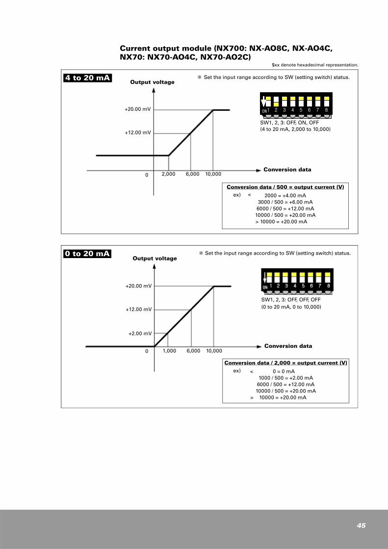
Current output module (NX700: NX-AO8C, NX-AO4C, NX70: NX70-AO4C, NX70-AO2C)
Output voltage※ Set the input range according to SW (setting switch) status.
SW1, 2, 3: OFF, ON, OFF(4 to 20 mA, 2,000 to 10,000)
Conversion data
Conversion data / 500 = output current (V)
2000 = +4.00 mA3000 / 500 = +6.00 mA6000 / 500 = +12.00 mA
10000 / 500 = +20.00 mA > 10000 = +20.00 mA
4 to 20 mA
ex) <
+20.00 mV
+12.00 mV
2,000 6,000 10,0000
ON1 2 3 4 5 6 7 8
Output voltage※ Set the input range according to SW (setting switch) status.
SW1, 2, 3: OFF, OFF, OFF(0 to 20 mA, 0 to 10,000)
Conversion data
Conversion data / 2,000 = output current (V)
< 0 = 0 mA1000 / 500 = +2.00 mA
6000 / 500 = +12.00 mA10000 / 500 = +20.00 mA
> 10000 = +20.00 mA
0 to 20 mA
ex)
+20.00 mV
+12.00 mV
1,000 6,000 10,000
+2.00 mV
0
$xx denote hexadecimal representation.
45
46
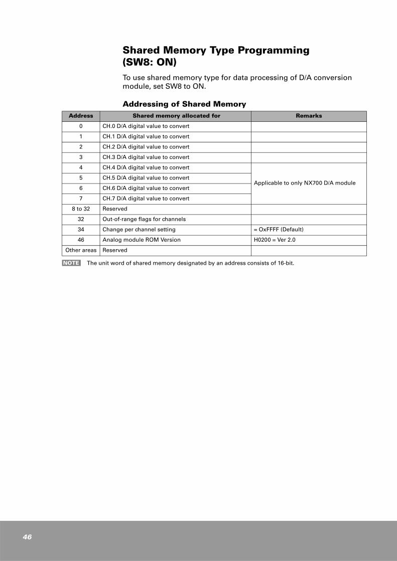
Shared Memory Type Programming (SW8: ON)To use shared memory type for data processing of D/A conversion module, set SW8 to ON.
Addressing of Shared MemoryAddress Shared memory allocated for Remarks
0 CH.0 D/A digital value to convert
1 CH.1 D/A digital value to convert
2 CH.2 D/A digital value to convert
3 CH.3 D/A digital value to convert
4 CH.4 D/A digital value to convert
Applicable to only NX700 D/A module5 CH.5 D/A digital value to convert
6 CH.6 D/A digital value to convert
7 CH.7 D/A digital value to convert
8 to 32 Reserved
32 Out-of-range flags for channels
34 Change per channel setting = OxFFFF (Default)
46 Analog module ROM Version H0200 = Ver 2.0
Other areas Reserved
The unit word of shared memory designated by an address consists of 16-bit.NOTE
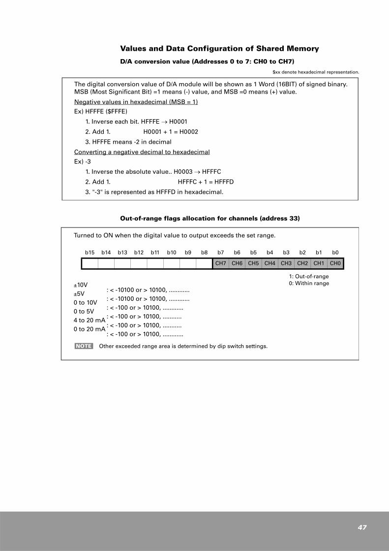
Values and Data Configuration of Shared Memory
D/A conversion value (Addresses 0 to 7: CH0 to CH7)
$xx denote hexadecimal representation.
Out-of-range flags allocation for channels (address 33)
The digital conversion value of D/A module will be shown as 1 Word (16BIT) of signed binary.MSB (Most Significant Bit) =1 means (-) value, and MSB =0 means (+) value.
Negative values in hexadecimal (MSB = 1)
Ex) HFFFE ($FFFE)
1. Inverse each bit. HFFFE → H0001
2. Add 1. H0001 + 1 = H0002
3. HFFFE means -2 in decimal
Converting a negative decimal to hexadecimal
Ex) -3
1. Inverse the absolute value.. H0003 → HFFFC
2. Add 1. HFFFC + 1 = HFFFD
3. "-3" is represented as HFFFD in hexadecimal.
Turned to ON when the digital value to output exceeds the set range.
±10V ±5V 0 to 10V 0 to 5V 4 to 20 mA 0 to 20 mA
b15 b14 b13 b12 b11 b10 b9 b8 b7 b6 b5 b4 b3 b2 b1 b0
CH7 CH6 CH5 CH4 CH3 CH2 CH1 CH0
Other exceeded range area is determined by dip switch settings.NOTE
1: Out-of-range0: Within range
: < -10100 or > 10100, ............: < -10100 or > 10100, ............: < -100 or > 10100, ............: < -100 or > 10100, ...........: < -100 or > 10100, ...........: < -100 or > 10100, ............
47
48
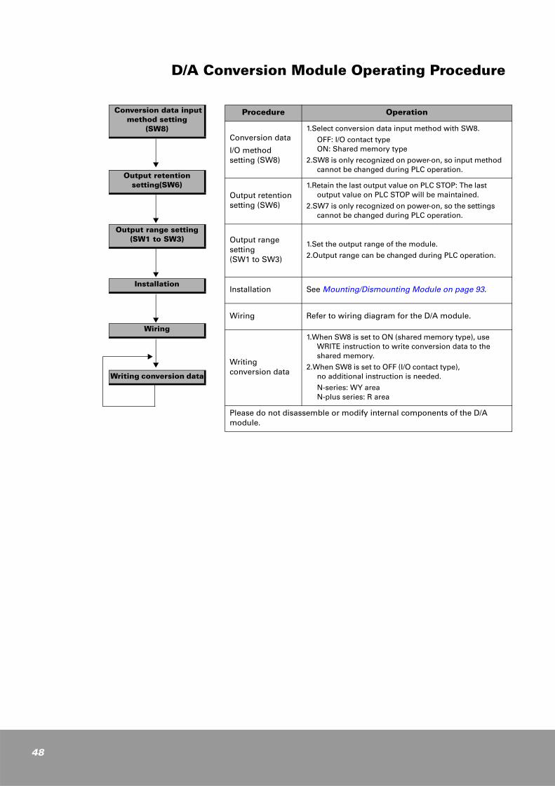
D/A Conversion Module Operating Procedure
Procedure Operation
Conversion data
I/O method setting (SW8)
1.Select conversion data input method with SW8.
OFF: I/O contact typeON: Shared memory type
2.SW8 is only recognized on power-on, so input method cannot be changed during PLC operation.
Output retention setting (SW6)
1.Retain the last output value on PLC STOP: The last output value on PLC STOP will be maintained.
2.SW7 is only recognized on power-on, so the settings cannot be changed during PLC operation.
Output range setting(SW1 to SW3)
1.Set the output range of the module.
2.Output range can be changed during PLC operation.
Installation See Mounting/Dismounting Module on page 93.
Wiring Refer to wiring diagram for the D/A module.
Writingconversion data
1.When SW8 is set to ON (shared memory type), use WRITE instruction to write conversion data to the shared memory.
2.When SW8 is set to OFF (I/O contact type), no additional instruction is needed.
N-series: WY areaN-plus series: R area
Please do not disassemble or modify internal components of the D/A module.
Conversion data input method setting
(SW8)
Output retention setting(SW6)
Output range setting(SW1 to SW3)
Installation
Wiring
Writing conversion data
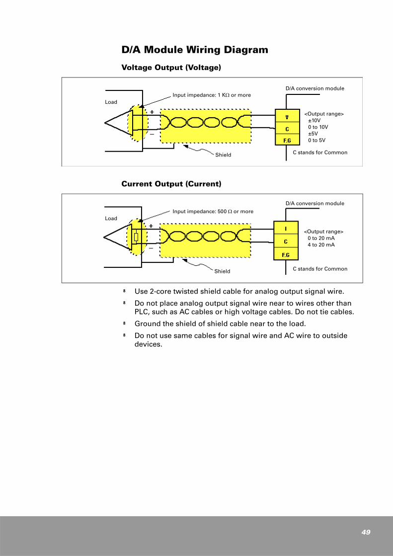
D/A Module Wiring Diagram
Voltage Output (Voltage)
Current Output (Current)
k Use 2-core twisted shield cable for analog output signal wire.k Do not place analog output signal wire near to wires other than
PLC, such as AC cables or high voltage cables. Do not tie cables.k Ground the shield of shield cable near to the load.k Do not use same cables for signal wire and AC wire to outside
devices.
Input impedance: 1 KΩ or moreLoad
Shield
D/A conversion module
<Output range>±10V0 to 10V±5V0 to 5V
C stands for Common
Input impedance: 500 Ω or moreLoad
Shield
D/A conversion module
<Output range>0 to 20 mA4 to 20 mA
C stands for Common
49

50
Programming• Programming methods are different for N-Series and N-plus Series.
N-series: NX70 (NX70-CPU750, NX70-CPU70), NX700(NX-CPU700, NX-CPU750A to NX-CPU750D) PLC CPU module Use WinFPST for programing
N-plus series: NX70 (NX-CPU70p1, NX70-CPU70p2), NX700 (NX-CPU700p) Use WinGPC for programing
• I/O contact type
No additional instruction is needed for I/O contact type. (ex. Slot 0 installation)
N-series: WY0 (Ch0), WY1 (Ch1), WY2 (Ch2), WY3 (Ch3),....
N-plus series: R0 (Ch0), R1 (Ch1), R2 (Ch2), R3 (Ch3),...
• Shared memory type
WRITE instruction is used for writing the data to convert, and
READ instruction is used for reading conversion data. Out-of-range flags are provided.
I/O Contact Type Programming (SW8: OFF)
When D/A conversion unit is installed in "slot 0"
k D/A conversion data is allocated to output contact. Additional programming is not needed for writing conversion data.
k CPU periodically updates the allocated input contacts with conversion data at every scan.
N-series (NX70: NX70-CPU70, NX70-CPU750, NX700: NX-CPU700, NX-CPU750A, B, C, D): WinFPST S/W
N-plus Series (NX70: NX70-CPU70p1, NX70-CPU70p2, NX700: NX-CPU700p): WinGPC S/W
[D/A conversion data]
WY0: CH0 data to convertWY1: CH1 data to convertWY2: CH2 data to convertWY3: CH3 data to convert
...WY7: CH7 data to convert
[D/A conversion data]
R0: CH0 data to convertR1: CH1 data to convertR2: CH2 data to convertR3: CH3 data to convert
...R7: CH7 data to convert
[ F0 MV, DT0, WY0 ]
LETD = R0S = W0
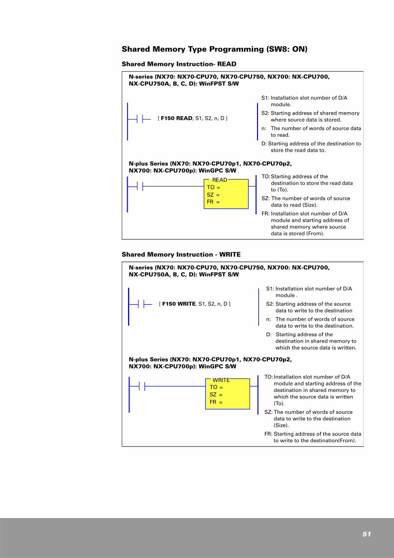
Shared Memory Type Programming (SW8: ON)
Shared Memory Instruction- READ
Shared Memory Instruction - WRITE
N-series (NX70: NX70-CPU70, NX70-CPU750, NX700: NX-CPU700, NX-CPU750A, B, C, D): WinFPST S/W
N-plus Series (NX70: NX70-CPU70p1, NX70-CPU70p2, NX700: NX-CPU700p): WinGPC S/W
S1: Installation slot number of D/A module.
S2: Starting address of shared memory where source data is stored.
n: The number of words of source data to read.
D: Starting address of the destination to store the read data to.
TO: Starting address of the destination to store the read data to (To).
SZ: The number of words of source data to read (Size).
FR: Installation slot number of D/A module and starting address of shared memory where source data is stored (From).
[ F150 READ, S1, S2, n, D ]
READTO =SZ =FR =
N-series (NX70: NX70-CPU70, NX70-CPU750, NX700: NX-CPU700, NX-CPU750A, B, C, D): WinFPST S/W
N-plus Series (NX70: NX70-CPU70p1, NX70-CPU70p2, NX700: NX-CPU700p): WinGPC S/W
S1: Installation slot number of D/A module .
S2: Starting address of the source data to write to the destination
n: The number of words of source data to write to the destination.
D: Starting address of the destination in shared memory to which the source data is written.
TO: Installation slot number of D/A module and starting address of the destination in shared memory to which the source data is written (To).
SZ: The number of words of source data to write to the destination (Size).
FR: Starting address of the source data to write to the destination(From).
[ F150 WRITE, S1, S2, n, D ]
WRITETO =SZ =FR =
51
52
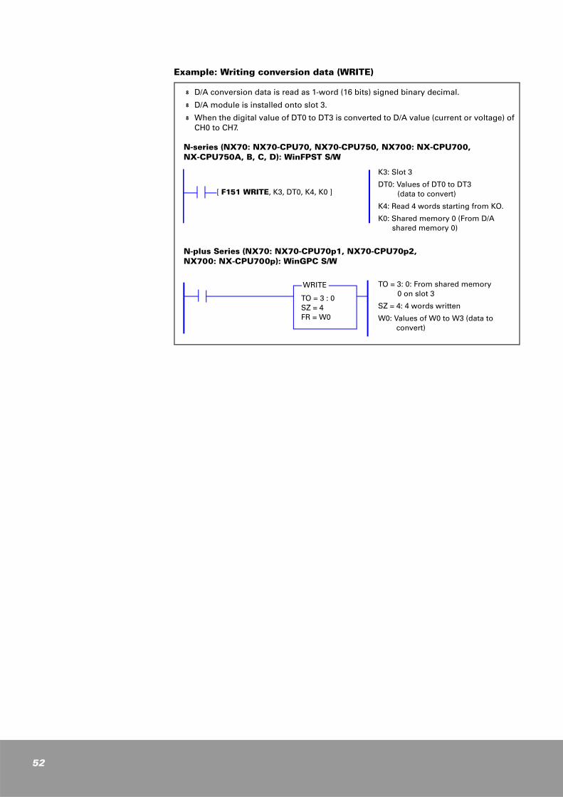
Example: Writing conversion data (WRITE)
k D/A conversion data is read as 1-word (16 bits) signed binary decimal.
k D/A module is installed onto slot 3.
k When the digital value of DT0 to DT3 is converted to D/A value (current or voltage) of CH0 to CH7.
N-series (NX70: NX70-CPU70, NX70-CPU750, NX700: NX-CPU700, NX-CPU750A, B, C, D): WinFPST S/W
N-plus Series (NX70: NX70-CPU70p1, NX70-CPU70p2, NX700: NX-CPU700p): WinGPC S/W
K3: Slot 3
DT0: Values of DT0 to DT3(data to convert)
K4: Read 4 words starting from KO.
K0: Shared memory 0 (From D/A shared memory 0)
TO = 3: 0: From shared memory 0 on slot 3
SZ = 4: 4 words written
W0: Values of W0 to W3 (data to convert)
[ F151 WRITE, K3, DT0, K4, K0 ]
TO = 3 : 0SZ = 4FR = W0
WRITE
4
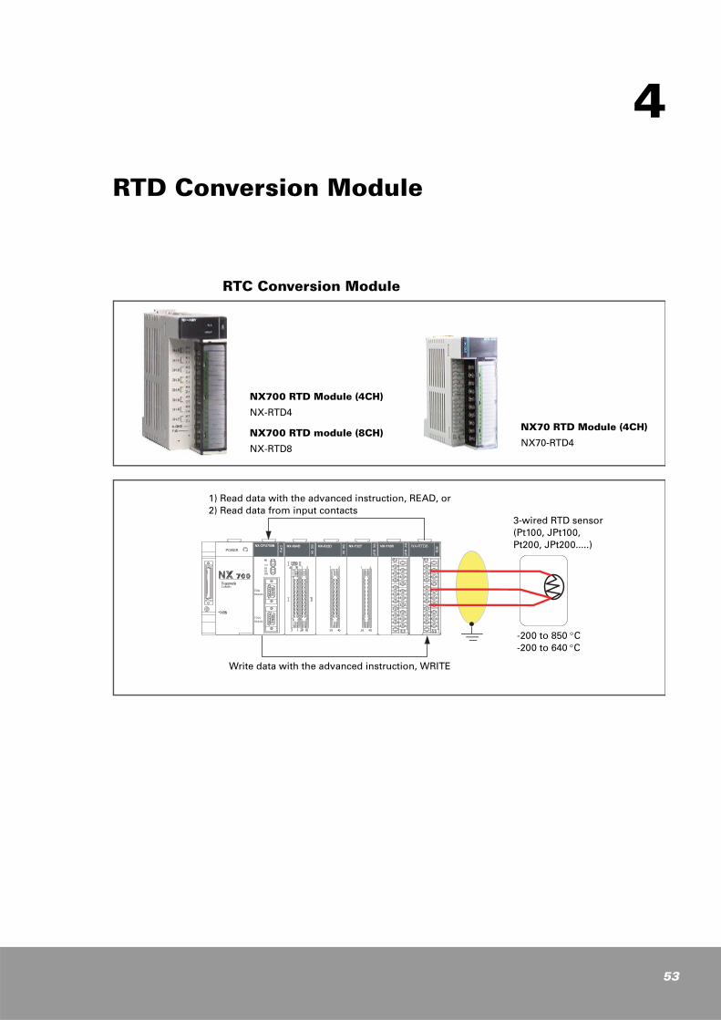
RTD Conversion Module
RTC Conversion Module
NX700 RTD Module (4CH)
NX-RTD4
NX700 RTD module (8CH)
NX-RTD8
NX70 RTD Module (4CH)
NX70-RTD4
1) Read data with the advanced instruction, READ, or2) Read data from input contacts
Write data with the advanced instruction, WRITE
3-wired RTD sensor (Pt100, JPt100, Pt200, JPt200.....)
-200 to 850 °C-200 to 640 °C
53

54
RTD Conversion Module Features
24-bit Σ−D A/D converter enables high accuracy and fast speed. Wide I/O range and self-calibration feature are also implemented.
1. NX700 RTD module: 4 channels or 8 channels/moduleNX70 RTD module: 4 channels/module
2. Type of temperature sensor3-wire platinum sensor is available. (Pt100, Pt200, Jpt100, Jpt200......)
3. Data both in Celsius (°C) and Fahrenheit (°F) are usable. You can select this with DIP switch on the bottom of the module.
4. Two programming methods Provide two programming methods. You can select an appropriate method according to the occupied I/O points:
Using shared memory Using I/O contacts
5. Designed for strong noise immunity The built-in analog & digital noise filter provides superior immunity against interference from outside.

RTD Conversion Module Specifications RTD (Resistive Temperature Detectors)
NX700/NX70 RTD (Resistive Temperature Detectors) Input
Catalog numberNX700 PLC, NX-RTD8(8 channels / module)
NX700 PLC, NX-RTD4(4 channels / module)
NX70 PLC, NX70-RTD4(4 channels / module)
RTD sensor 3-Wire
Number of RTD input channels
8 Channels 4 Channels 4 Channels
Digital conversion Signed 16-bit binary (2's complement)
Converter type 24-bit Σ−D A/D Converter
I/O characteristics(Temperature sensor and digital output)
Pt100 (a=0.00385, -200 to 850 °C => -2,000 to 8,500) 300 Ω (10m Ω/BIT)
Pt200, Pt500, Pt1000 1.2K Ω (20m Ω/BIT)
JPt100 (a=0.00385, -200 to 640 °C => -2,000 to 6,400 2000 Ω (100m Ω/BIT)
Jpt200, Jpt500, Jpt1000 NI100, NI120, CU10
Max. resolution 0.1 °C, 0.1 °F, 10 mΩ, 20 mΩ
Overall accuracy ±0.1 %/F.S (25 °C)
Conversion speed 60 ms/CH
External input impedance
10 MΩ
Current source 1 mA (Excitation Current)
Isolation methodBetween input channel and internal circuit: DC/DC converter and photocoupler Isolation Between input channels: Non-isolation
Number of I/O points
I/O contact type: 128 points inputShared memory type: 16 points input
I/O contact type: 64 points input Shared memory type: 16 points input
Internal current consumption (5 V)
Internal power 5 V 340 mA or lessInternal power 5 V 330 mA or less
External connection method
20-pin removable terminal block (M3.5) 20-pin terminal block (M3.0)
RTD Sensor (Pt100, JPt100)
-200 to 850 °C-200 to 640 °C
3- Wire type for the correction of resistance between the lines.
3-Wire of +, -, GNDConversion to temperature (°C, °F)
RTD conversion module
55
56
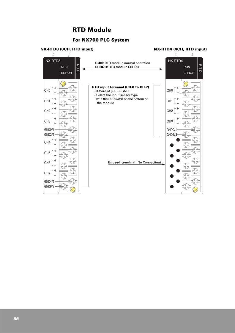
RTD Module
For NX700 PLC System
NX-RTD8 (8CH, RTD input) NX-RTD4 (4CH, RTD input)
RTD input terminal (CH.0 to CH.7) - 3-Wire of (+), (-), GND- Select the input sensor type with the DIP switch on the bottom of the module
RUN: RTD module normal operation ERROR: RTD module ERROR
Unused terminal (No Connection)
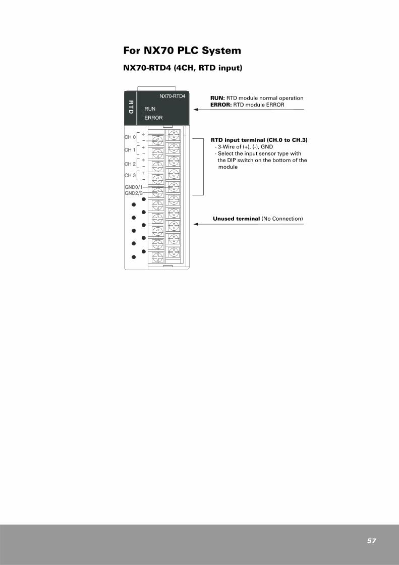
For NX70 PLC System
NX70-RTD4 (4CH, RTD input)
RUN: RTD module normal operationERROR: RTD module ERROR
RTD input terminal (CH.0 to CH.3)- 3-Wire of (+), (-), GND- Select the input sensor type with the DIP switch on the bottom of the module
Unused terminal (No Connection)
57

58
RTD Module Input Range SelectionDip switch is located on the bottom of the module.
Dip Switch Settings
SW1 to SW4: Input range setting
SW8: Conversion data I/O method setting
SW8: Select conversion data I/O methodOFF: Set the I/O method to I/O contact type.ON: Set the I/O method to shared memory type.
SW7: Temperature unit settingOFF: °C ON: °FSW1 to 4:
Input rangeSW5 and 6:Filter setting
SW1 SW2 SW3 SW4 Input range and conversion data Remarks
OFF OFF OFF OFF PT100, 0.00385, -200 to 850 °C, 0.1 °C or 0.1 °F/count
ON OFF OFF OFF PT200, 0.00385, -200 to 850 °C, 0.1 °C or 0.1 °F/count
OFF ON OFF OFF PT500, 0.00385, -200 to 850 °C, 0.1 °C or 0.1 °F/count
ON ON OFF OFF PT1000, 0.00385, -200 to 270 °C, 0.1 °C or 0.1 °F/count
OFF OFF ON OFF JPT100, 0.003916, -200 to 640 °C, 0.1 °C or 0.1 °F/count
ON OFF ON OFF JPT200, 0.003916, -200 to 640 °C, 0.1 °C or 0.1 °F/count
OFF ON ON OFF JPT500, 0.003916, -200 to 640 °C, 0.1 °C or 0.1 °F/count
ON ON ON OFF NI100, 0.00618, -60 to 250 °C, 0.1 °C or 0.1 °F/count
OFF OFF OFF ON NI200, 0.00618, -60 to 250 °C, 0.1 °C or 0.1 °F/count
ON OFF OFF ON NI500, 0.00618, -60 to 250 °C, 0.1 °C or 0.1 °F/count
OFF ON OFF ON NI120, 0.00672, -80 to 250 °C, 0.1 °C or 0.1 °F/count
ON ON OFF ON CU10, 0.00427, -200 to 260 °C, 0.1 °C or 0.1 °F/count
OFF OFF ON ON Resistance Input, 1 to 2,000 Ω, 100 mΩ/1count
ON OFF ON ON Resistance Input, 1 to 327 Ω, 10 mΩ/1count
OFF ON ON ON Resistance Input, 1 to 1.2 KΩ, 50 mΩ/1count
ON ON ON ON Not Used
SW5 to SW6: Filter setting
SW5 SW6 Filter setting Remarks
OFF OFF Filter #0 Activating a filter that has a higher filter number produces more stable conversion data but slower conversion speed.
ON OFF Filter #1
OFF ON Filter #2
ON ON Filter #3
SW8 RTD 8CH
RTD 4CH
Conversion data input method
Input range and conversion data
OFF 128
points input
64 points input
I/O contact type(I/O conversion data)
Easy to use.
User programming for reading conversion data is not needed.
ON 16 pointsShared memory type (I/O conversion data)
READ instruction on user program is needed for reading conversion data.
Range excess feature available.
SW7: Temperature unit setting
SW7 Temperature unit
OFF 0.1 °C
ON 0.1 °F
°F = (9/5) x °C + 32
I/O Method for CPU ModuleSW8 setting determines how the CPU module handles conversion data from RTD module.
When SW8 is set to OFF, as many words of input contacts as the channels are allocated and the CPU module updates these input contacts every scan, which allows you to read conversion data of RTD modules from these input contacts.
When SW8 is set to ON, only 1-word input contact is allocated and conversion data are stored in shared memory. You should use the READ instruction to read conversion data of RTD modules stored in this shared memory. The 1-word input contact allocated is used as out-of-range flags that indicate whether the conversion data of RTD modules exceed the range or not.
I/O Contact Type (SW8, OFF)
Data conversion method is set to I/O contact type. (SW8 is set to OFF.)
k When an RTD module is mounted onto the first I/O slot (slot 0) and SW8 is set to OFF (I/O contact type), 4-word (64 points) input contacts are allocated for 4-channel RTD module and 8-word (128 points) for 8-channel RTD module.
For 8-channel RTD module (NX700: NX-RTD8)
1. NX-series: 8 words (128 points input): WX0 (Ch0), WX1 (Ch1), WX2 (Ch2), .........WX7 (Ch7)
2. NX-plus series: 8 words (128 points input): R0 (Ch0), R1 (Ch1), R2 (Ch2), .......R7 (Ch7)
For 4-channel RTD module (NX700: NX-RTD4, NX70: NX70-RTD4)
1. NX-series: 4 words (64 points input): WX0 (Ch0), WX1 (Ch1), WX2 (Ch2), WX3 (Ch3)
2. NX-plus series: 4 words (64 points input): R0 (Ch0), R1 (Ch1), R2 (Ch2), R3 (Ch3)
k If the data conversion method is set to I/O contact type, many input contacts are used but you need not to use the READ (or RMRD) instruction to read RTD conversion data because the CPU module automatically updates them every scan. Therefore, no additional programming is required to read RTD conversion data.
59
60
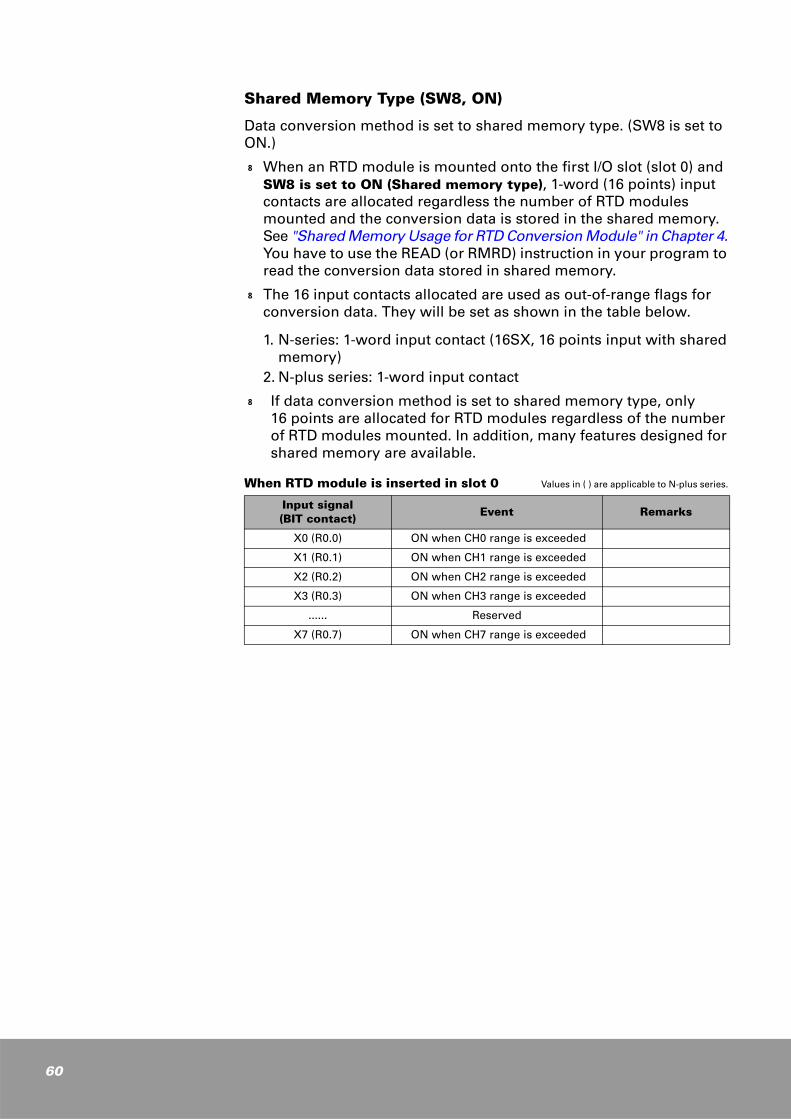
Shared Memory Type (SW8, ON)
Data conversion method is set to shared memory type. (SW8 is set to ON.)
k When an RTD module is mounted onto the first I/O slot (slot 0) and SW8 is set to ON (Shared memory type), 1-word (16 points) input contacts are allocated regardless the number of RTD modules mounted and the conversion data is stored in the shared memory. See "Shared Memory Usage for RTD Conversion Module" in Chapter 4. You have to use the READ (or RMRD) instruction in your program to read the conversion data stored in shared memory.
k The 16 input contacts allocated are used as out-of-range flags for conversion data. They will be set as shown in the table below.
1. N-series: 1-word input contact (16SX, 16 points input with shared memory)
2. N-plus series: 1-word input contact
k If data conversion method is set to shared memory type, only 16 points are allocated for RTD modules regardless of the number of RTD modules mounted. In addition, many features designed for shared memory are available.
When RTD module is inserted in slot 0 Values in ( ) are applicable to N-plus series.
Input signal (BIT contact)
Event Remarks
X0 (R0.0) ON when CH0 range is exceeded
X1 (R0.1) ON when CH1 range is exceeded
X2 (R0.2) ON when CH2 range is exceeded
X3 (R0.3) ON when CH3 range is exceeded
...... Reserved
X7 (R0.7) ON when CH7 range is exceeded
I/O Conversion Characteristics
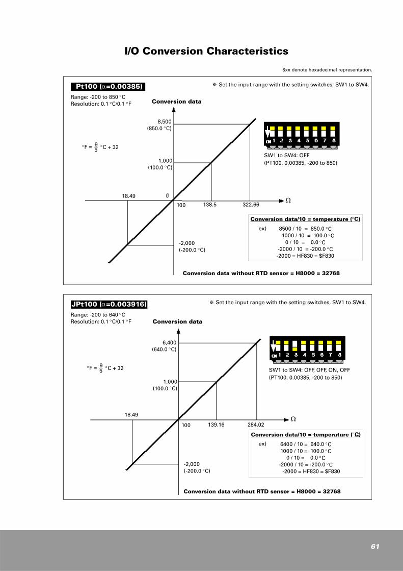
Range: -200 to 850 °CResolution: 0.1 °C/0.1 °F
※ Set the input range with the setting switches, SW1 to SW4.
Conversion data without RTD sensor = H8000 = 32768
Conversion data/10 = temperature (°C)
8500 / 10 = 850.0 °C 1000 / 10 = 100.0 °C
0 / 10 = 0.0 °C-2000 / 10 = -200.0 °C-2000 = HF830 = $F830
SW1 to SW4: OFF(PT100, 0.00385, -200 to 850)
8,500(850.0 °C)
1,000(100.0 °C)
18.49
100 138.5 322.66
°F = 9
− °C + 32 5
Pt100 (α=0.00385)
Conversion data
-2,000(-200.0 °C)
Ω
ex)
Range: -200 to 640 °CResolution: 0.1 °C/0.1 °F
※ Set the input range with the setting switches, SW1 to SW4.
Conversion data without RTD sensor = H8000 = 32768
Conversion data/10 = temperature (°C)
6400 / 10 = 640.0 °C1000 / 10 = 100.0 °C
0 / 10 = 0.0 °C-2000 / 10 = -200.0 °C
-2000 = HF830 = $F830
SW1 to SW4: OFF, OFF, ON, OFF(PT100, 0.00385, -200 to 850)
6,400(640.0 °C)
1,000(100.0 °C)
18.49
100 139.16 284.02
°F = 9
− °C + 32 5
JPt100 (α=0.003916)
Conversion data
-2,000(-200.0 °C)
Ω
ex)
$xx denote hexadecimal representation.
61
62
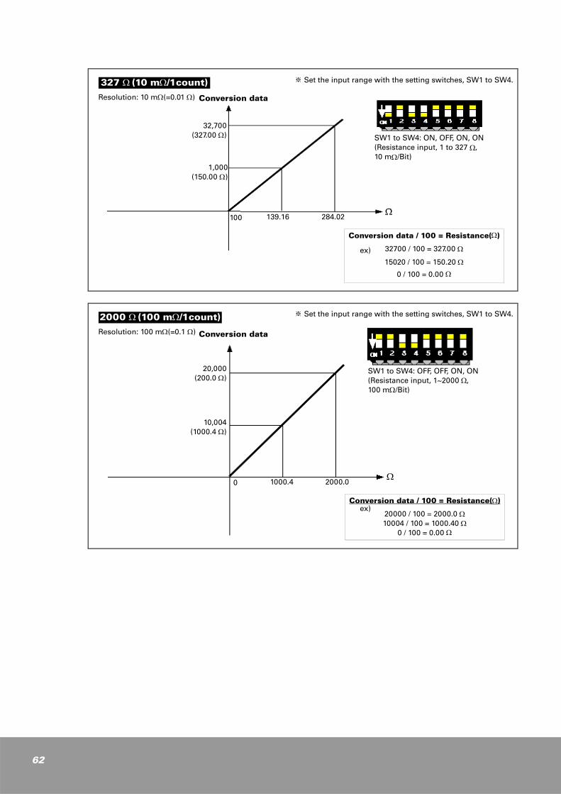
Resolution: 10 mΩ(=0.01 Ω)
※ Set the input range with the setting switches, SW1 to SW4.
Conversion data / 100 = Resistance(Ω)
32700 / 100 = 327.00 Ω
15020 / 100 = 150.20 Ω
0 / 100 = 0.00 Ω
SW1 to SW4: ON, OFF, ON, ON (Resistance input, 1 to 327 Ω, 10 mΩ/Bit)
32,700(327.00 Ω)
1,000(150.00 Ω)
100 139.16 284.02
327 Ω (10 mΩ/1count)
Conversion data
Ω
ex)
20,000(200.0 Ω)
10,004(1000.4 Ω)
0 1000.4 2000.0
Resolution: 100 mΩ(=0.1 Ω)
※ Set the input range with the setting switches, SW1 to SW4.
Conversion data / 100 = Resistance(Ω)
20000 / 100 = 2000.0 Ω10004 / 100 = 1000.40 Ω
0 / 100 = 0.00 Ω
SW1 to SW4: OFF, OFF, ON, ON(Resistance input, 1~2000 Ω, 100 mΩ/Bit)
2000 Ω (100 mΩ/1count)
Conversion data
Ω
ex)
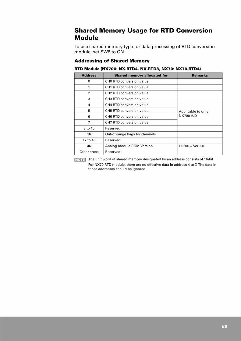
Shared Memory Usage for RTD Conversion ModuleTo use shared memory type for data processing of RTD conversion module, set SW8 to ON.
Addressing of Shared Memory
RTD Module (NX700: NX-RTD4, NX-RTD8, NX70: NX70-RTD4)
Address Shared memory allocated for Remarks
0 CH0 RTD conversion value
1 CH1 RTD conversion value
2 CH2 RTD conversion value
3 CH3 RTD conversion value
4 CH4 RTD conversion value
Applicable to onlyNX700 A/D
5 CH5 RTD conversion value
6 CH6 RTD conversion value
7 CH7 RTD conversion value
8 to 15 Reserved
16 Out-of-range flags for channels
17 to 45 Reserved
46 Analog module ROM Version H0200 = Ver 2.0
Other areas Reserved
The unit word of shared memory designated by an address consists of 16-bit.
For NX70 RTD module, there are no effective data in address 4 to 7. The data in those addresses should be ignored.
NOTE
63
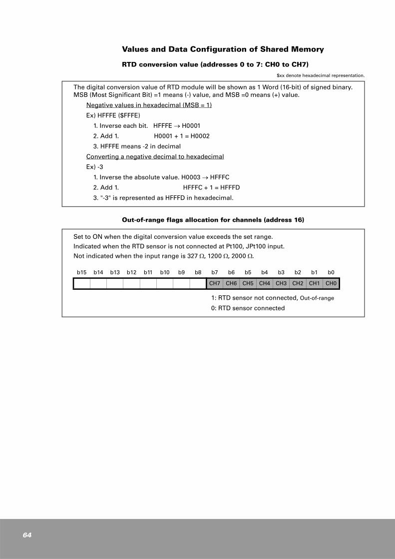
64
Values and Data Configuration of Shared Memory
RTD conversion value (addresses 0 to 7: CH0 to CH7)
$xx denote hexadecimal representation.
Out-of-range flags allocation for channels (address 16)
The digital conversion value of RTD module will be shown as 1 Word (16-bit) of signed binary. MSB (Most Significant Bit) =1 means (-) value, and MSB =0 means (+) value.
Negative values in hexadecimal (MSB = 1)
Ex) HFFFE ($FFFE)
1. Inverse each bit. HFFFE → H0001
2. Add 1. H0001 + 1 = H0002
3. HFFFE means -2 in decimal
Converting a negative decimal to hexadecimal
Ex) -3
1. Inverse the absolute value. H0003 → HFFFC
2. Add 1. HFFFC + 1 = HFFFD
3. "-3" is represented as HFFFD in hexadecimal.
Set to ON when the digital conversion value exceeds the set range.
Indicated when the RTD sensor is not connected at Pt100, JPt100 input.
Not indicated when the input range is 327 Ω, 1200 Ω, 2000 Ω.
1: RTD sensor not connected, Out-of-range
0: RTD sensor connected
b15 b14 b13 b12 b11 b10 b9 b8 b7 b6 b5 b4 b3 b2 b1 b0
CH7 CH6 CH5 CH4 CH3 CH2 CH1 CH0
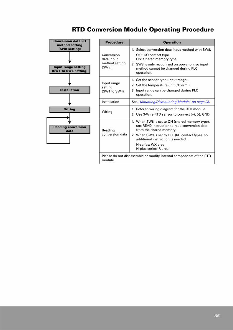
RTD Conversion Module Operating Procedure
Procedure Operation
Conversion data input method setting (SW8)
1. Select conversion data input method with SW8.
OFF: I/O contact typeON: Shared memory type
2. SW8 is only recognized on power-on, so input method cannot be changed during PLC operation.
Input range setting (SW1 to SW4)
1. Set the sensor type (input range).
2. Set the temperature unit (°C or °F).
3. Input range can be changed during PLC operation.
Installation See "Mounting/Dismounting Module" on page 93.
Wiring1. Refer to wiring diagram for the RTD module.
2. Use 3-Wire RTD sensor to connect (+), (-), GND
Reading conversion data
1. When SW8 is set to ON (shared memory type), use READ instruction to read conversion data from the shared memory.
2. When SW8 is set to OFF (I/O contact type), no additional instruction is needed.
N-series: WX areaN-plus series: R area
Please do not disassemble or modify internal components of the RTD module.
Conversion data I/O method setting(SW8 setting)
Input range setting(SW1 to SW4 setting)
Installation
Wiring
Reading conversiondata
65
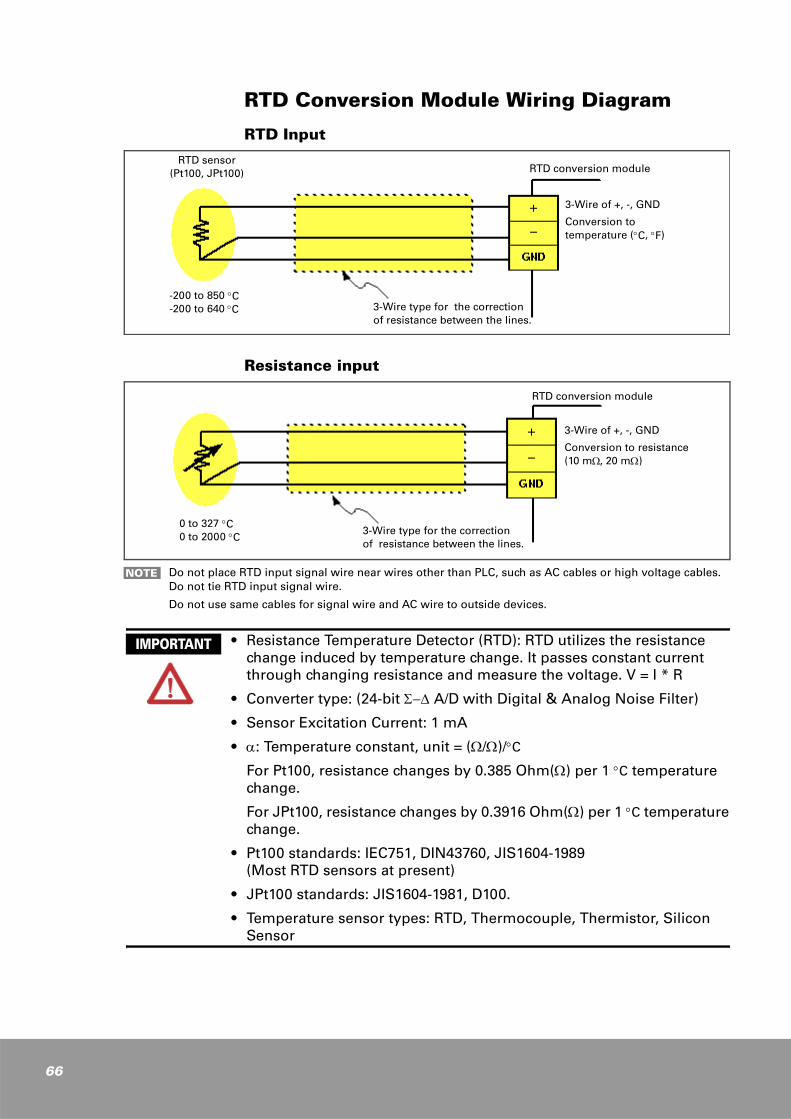
66
RTD Conversion Module Wiring Diagram
RTD Input
Resistance input
3-Wire type for the correction of resistance between the lines.
RTD conversion module
3-Wire of +, -, GND
Conversion totemperature (°C, °F)
RTD sensor(Pt100, JPt100)
-200 to 850 °C-200 to 640 °C
3-Wire type for the correction of resistance between the lines.
0 to 327 °C0 to 2000 °C
3-Wire of +, -, GND
Conversion to resistance(10 mΩ, 20 mΩ)
RTD conversion module
Do not place RTD input signal wire near wires other than PLC, such as AC cables or high voltage cables. Do not tie RTD input signal wire.
Do not use same cables for signal wire and AC wire to outside devices.
NOTE
• Resistance Temperature Detector (RTD): RTD utilizes the resistance change induced by temperature change. It passes constant current through changing resistance and measure the voltage. V = I * R
• Converter type: (24-bit Σ−∆ A/D with Digital & Analog Noise Filter)
• Sensor Excitation Current: 1 mA
• α: Temperature constant, unit = (Ω/Ω)/°C
For Pt100, resistance changes by 0.385 Ohm(Ω) per 1 °C temperature change.
For JPt100, resistance changes by 0.3916 Ohm(Ω) per 1 °C temperature change.
• Pt100 standards: IEC751, DIN43760, JIS1604-1989(Most RTD sensors at present)
• JPt100 standards: JIS1604-1981, D100.
• Temperature sensor types: RTD, Thermocouple, Thermistor, Silicon Sensor
IMPORTANT
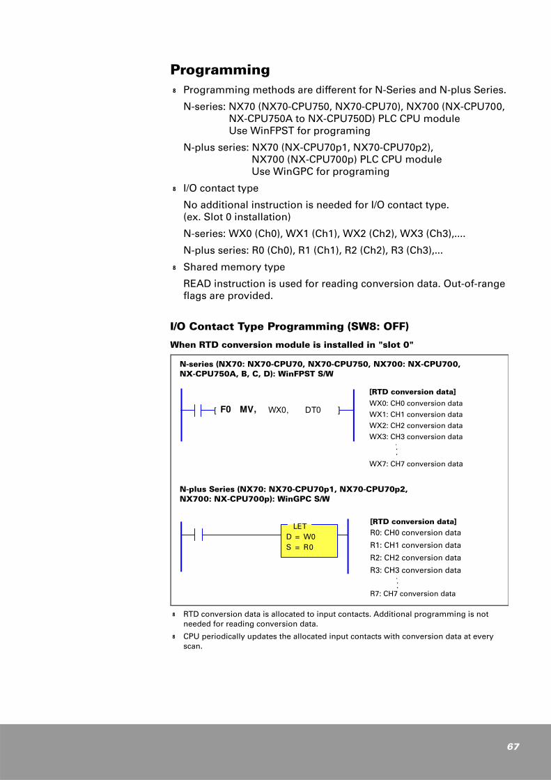
Programmingk Programming methods are different for N-Series and N-plus Series.
N-series: NX70 (NX70-CPU750, NX70-CPU70), NX700 (NX-CPU700, NX-CPU750A to NX-CPU750D) PLC CPU module Use WinFPST for programing
N-plus series: NX70 (NX-CPU70p1, NX70-CPU70p2), NX700 (NX-CPU700p) PLC CPU module Use WinGPC for programing
k I/O contact type
No additional instruction is needed for I/O contact type. (ex. Slot 0 installation)
N-series: WX0 (Ch0), WX1 (Ch1), WX2 (Ch2), WX3 (Ch3),....
N-plus series: R0 (Ch0), R1 (Ch1), R2 (Ch2), R3 (Ch3),...
k Shared memory type
READ instruction is used for reading conversion data. Out-of-range flags are provided.
I/O Contact Type Programming (SW8: OFF)
When RTD conversion module is installed in "slot 0"
k RTD conversion data is allocated to input contacts. Additional programming is not needed for reading conversion data.
k CPU periodically updates the allocated input contacts with conversion data at every scan.
N-series (NX70: NX70-CPU70, NX70-CPU750, NX700: NX-CPU700, NX-CPU750A, B, C, D): WinFPST S/W
N-plus Series (NX70: NX70-CPU70p1, NX70-CPU70p2, NX700: NX-CPU700p): WinGPC S/W
[RTD conversion data]
WX0: CH0 conversion data
WX1: CH1 conversion data
WX2: CH2 conversion data
WX3: CH3 conversion data ...
WX7: CH7 conversion data
[ F0 MV, WX0, DT0 ]
[RTD conversion data]R0: CH0 conversion data
R1: CH1 conversion data
R2: CH2 conversion data
R3: CH3 conversion data ...
R7: CH7 conversion data
LETD = W0S = R0
67
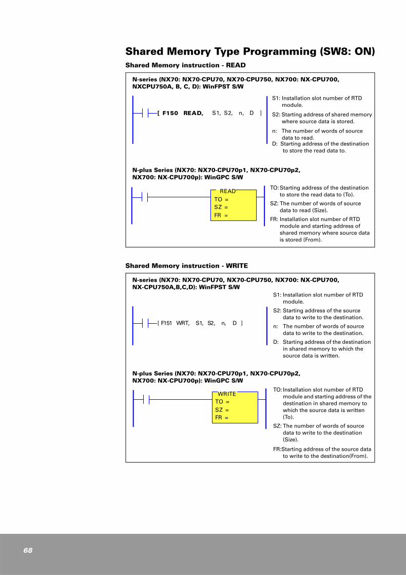
68
Shared Memory Type Programming (SW8: ON)Shared Memory instruction - READ
Shared Memory instruction - WRITE
N-series (NX70: NX70-CPU70, NX70-CPU750, NX700: NX-CPU700, NXCPU750A, B, C, D): WinFPST S/W
N-plus Series (NX70: NX70-CPU70p1, NX70-CPU70p2, NX700: NX-CPU700p): WinGPC S/W
S1: Installation slot number of RTD module.
S2: Starting address of shared memory where source data is stored.
n: The number of words of source data to read.
D: Starting address of the destination to store the read data to.
[ F150 READ, S1, S2, n, D ]
TO: Starting address of the destination to store the read data to (To).
SZ: The number of words of source data to read (Size).
FR: Installation slot number of RTD module and starting address of shared memory where source data is stored (From).
READTO =SZ =FR =
N-series (NX70: NX70-CPU70, NX70-CPU750, NX700: NX-CPU700, NX-CPU750A,B,C,D): WinFPST S/W
N-plus Series (NX70: NX70-CPU70p1, NX70-CPU70p2, NX700: NX-CPU700p): WinGPC S/W
S1: Installation slot number of RTD module.
S2: Starting address of the source data to write to the destination.
n: The number of words of source data to write to the destination.
D: Starting address of the destination in shared memory to which the source data is written.
[ F151 WRT, S1, S2, n, D ]
TO: Installation slot number of RTD module and starting address of the destination in shared memory to which the source data is written (To).
SZ: The number of words of source data to write to the destination (Size).
FR:Starting address of the source data to write to the destination(From).
WRITETO =SZ =FR =
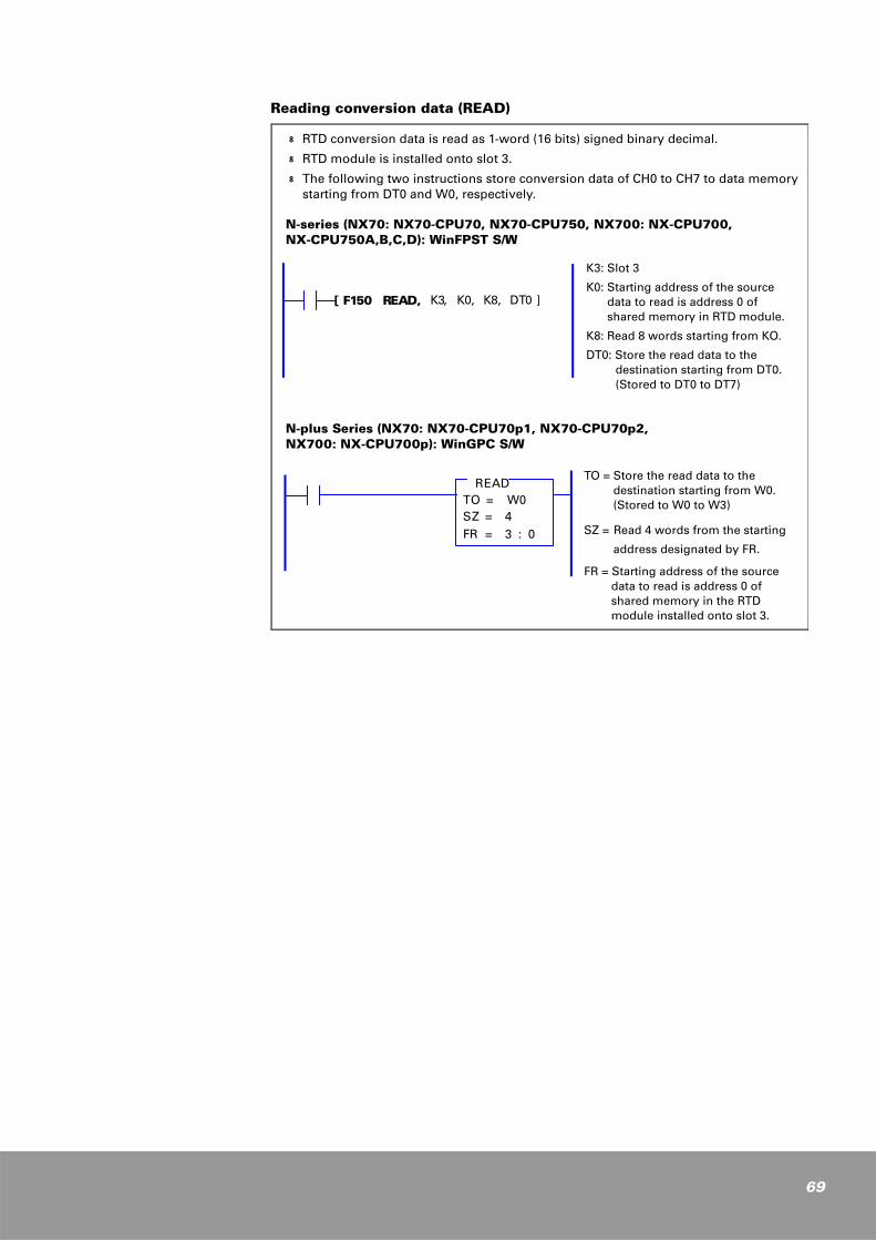
Reading conversion data (READ)
k RTD conversion data is read as 1-word (16 bits) signed binary decimal.
k RTD module is installed onto slot 3.
k The following two instructions store conversion data of CH0 to CH7 to data memory starting from DT0 and W0, respectively.
N-series (NX70: NX70-CPU70, NX70-CPU750, NX700: NX-CPU700, NX-CPU750A,B,C,D): WinFPST S/W
N-plus Series (NX70: NX70-CPU70p1, NX70-CPU70p2, NX700: NX-CPU700p): WinGPC S/W
K3: Slot 3
K0: Starting address of the source data to read is address 0 of shared memory in RTD module.
K8: Read 8 words starting from KO.
DT0: Store the read data to the destination starting from DT0.(Stored to DT0 to DT7)
[ F150 READ, K3, K0, K8, DT0 ]
TO = Store the read data to the destination starting from W0. (Stored to W0 to W3)
SZ = Read 4 words from the starting
address designated by FR.
FR = Starting address of the source data to read is address 0 of shared memory in the RTD module installed onto slot 3.
READTO = W0SZ = 4FR = 3 : 0
69

70
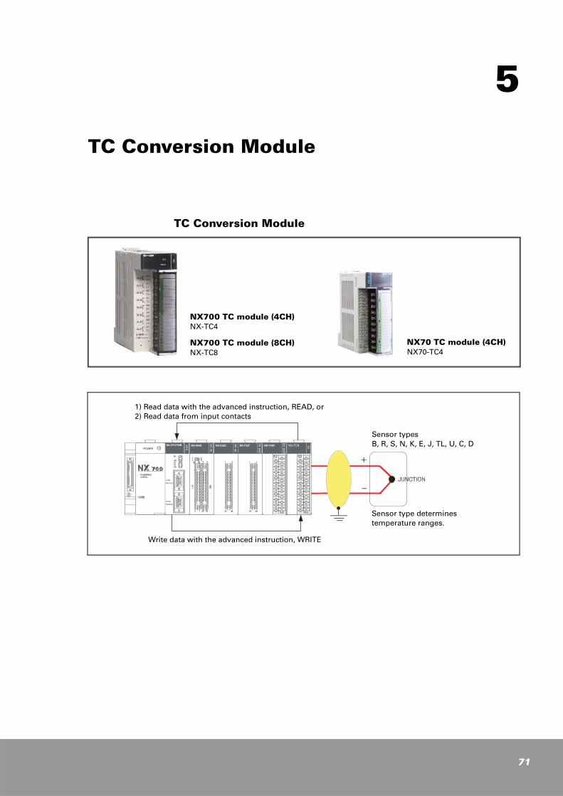
5
TC Conversion Module
TC Conversion Module
NX700 TC module (4CH)NX-TC4
NX700 TC module (8CH)NX-TC8
NX70 TC module (4CH)NX70-TC4
1) Read data with the advanced instruction, READ, or2) Read data from input contacts
Write data with the advanced instruction, WRITE
Sensor typesB, R, S, N, K, E, J, TL, U, C, D
Sensor type determinestemperature ranges.
71
72
TC Conversion Module Features
24-bit Σ-∆ A/D converter enables high accuracy and fast speed. Wide I/O range and self-calibration feature are also implemented.
1. NX700 TC module: 4 channels or 8 channels/moduleNX70 TC module: 4 channel/module
2. Temperature sensor typesAvailable types: B, R, S, N, K, E, J, T, L, U, C, D, 10 mV....
3. Data both in Celsius (°C) and Fahrenheit (°F) are usable.You can select this with dip switch on the bottom plane of the module.
4. Two programming methodsProvide two programming methods. You can select an appropriate method according to the occupied I/O points:
Using shared memory Using I/O contacts
5. Temperature compensation feature of TC moduleWhen using Thermocouple with the module, temperature compensation is needed because of the difference between actually measured temperature and module temperature. To handle this problem, the built-in temperature sensor provides temperature compensation feature.
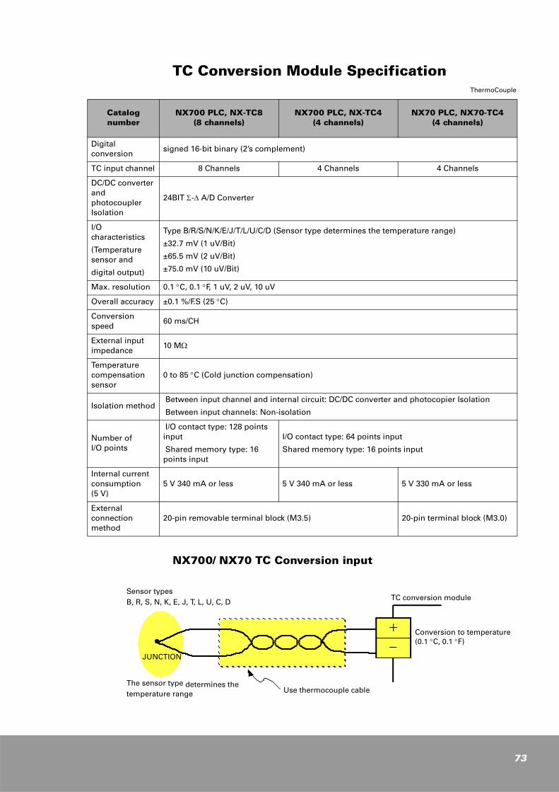
TC Conversion Module SpecificationThermoCouple
NX700/ NX70 TC Conversion input
Catalog number
NX700 PLC, NX-TC8 (8 channels)
NX700 PLC, NX-TC4 (4 channels)
NX70 PLC, NX70-TC4 (4 channels)
Digital conversion
signed 16-bit binary (2’s complement)
TC input channel 8 Channels 4 Channels 4 Channels
DC/DC converter and photocoupler Isolation
24BIT Σ-∆ A/D Converter
I/O characteristics
(Temperature sensor and
digital output)
Type B/R/S/N/K/E/J/T/L/U/C/D (Sensor type determines the temperature range)
±32.7 mV (1 uV/Bit)
±65.5 mV (2 uV/Bit)
±75.0 mV (10 uV/Bit)
Max. resolution 0.1 °C, 0.1 °F, 1 uV, 2 uV, 10 uV
Overall accuracy ±0.1 %/F.S (25 °C)
Conversion speed
60 ms/CH
External input impedance
10 MΩ
Temperature compensation sensor
0 to 85 °C (Cold junction compensation)
Isolation method Between input channel and internal circuit: DC/DC converter and photocopier Isolation
Between input channels: Non-isolation
Number ofI/O points
I/O contact type: 128 points input
Shared memory type: 16 points input
I/O contact type: 64 points input
Shared memory type: 16 points input
Internal current consumption (5 V)
5 V 340 mA or less 5 V 340 mA or less 5 V 330 mA or less
External connection method
20-pin removable terminal block (M3.5) 20-pin terminal block (M3.0)
Sensor typesB, R, S, N, K, E, J, T, L, U, C, D TC conversion module
The sensor type determines thetemperature range Use thermocouple cable
JUNCTION
Conversion to temperature(0.1 °C, 0.1 °F)
73
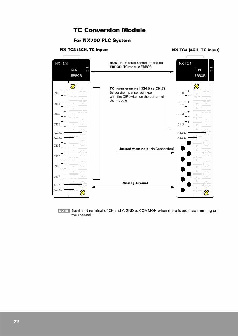
74
TC Conversion Module
For NX700 PLC System
TC
NX-TC8
RUN
ERROR
CH0+
CH1
CH2
CH3
-
-+
-+
-+
A.GND
A.GND
A.GND
A.GND
CH4+
CH5
CH6
CH7
-
-+
-+
+-
TC
NX-TC4
RUN
ERROR
CH0+
CH1
CH2
CH3
-
-+
-+
-+
A.GND
A.GND
RUN: TC module normal operationERROR: TC module ERROR
TC input terminal (CH.0 to CH.7)Select the input sensor typewith the DIP switch on the bottom of the module
Analog Ground
NX-TC8 (8CH, TC input) NX-TC4 (4CH, TC input)
Unused terminals (No Connection)
Set the (-) terminal of CH and A.GND to COMMON when there is too much hunting on the channel.
NOTE
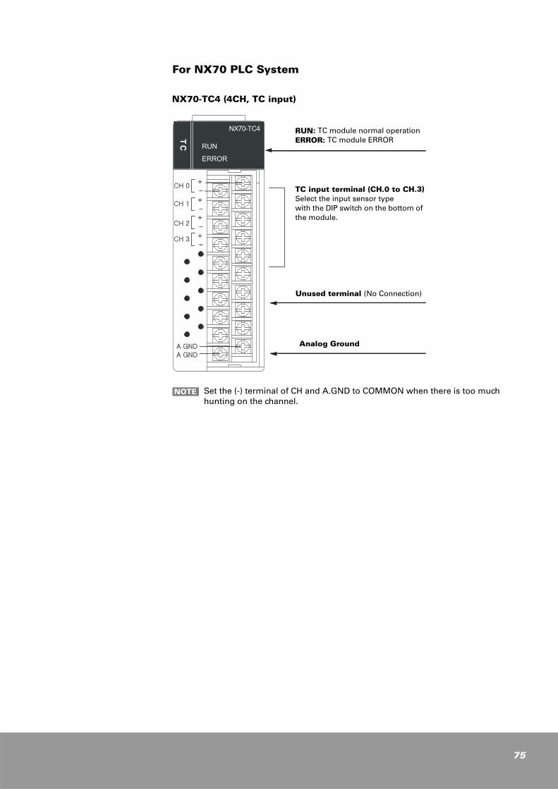
For NX70 PLC System
RUN: TC module normal operationERROR: TC module ERROR
TC input terminal (CH.0 to CH.3)Select the input sensor typewith the DIP switch on the bottom of the module.
NX70-TC4 (4CH, TC input)
Analog Ground
Unused terminal (No Connection)
Set the (-) terminal of CH and A.GND to COMMON when there is too much hunting on the channel.
NOTE
75
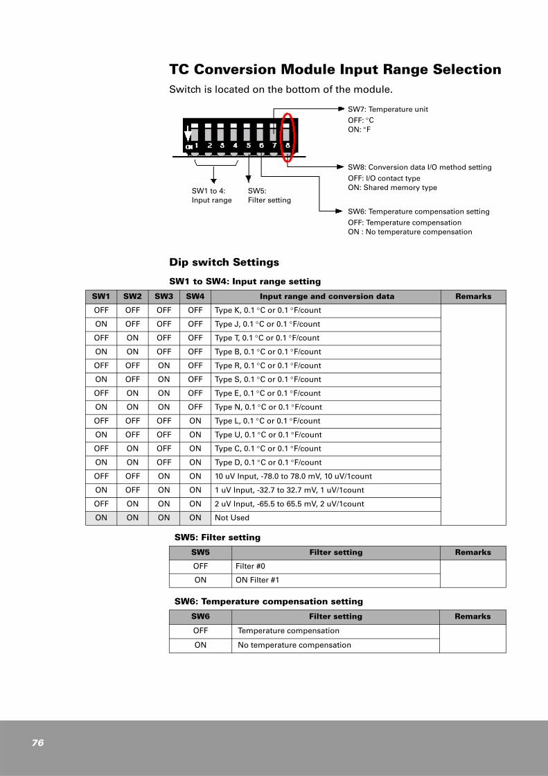
76
TC Conversion Module Input Range SelectionSwitch is located on the bottom of the module.
Dip switch Settings
SW1 to SW4: Input range setting
SW5: Filter setting
SW6: Temperature compensation setting
SW7: Temperature unit
OFF: °CON: °F
SW8: Conversion data I/O method setting
OFF: I/O contact type ON: Shared memory type
SW6: Temperature compensation setting
OFF: Temperature compensationON : No temperature compensation
SW1 to 4:Input range
SW5:Filter setting
SW1 SW2 SW3 SW4 Input range and conversion data Remarks
OFF OFF OFF OFF Type K, 0.1 °C or 0.1 °F/count
ON OFF OFF OFF Type J, 0.1 °C or 0.1 °F/count
OFF ON OFF OFF Type T, 0.1 °C or 0.1 °F/count
ON ON OFF OFF Type B, 0.1 °C or 0.1 °F/count
OFF OFF ON OFF Type R, 0.1 °C or 0.1 °F/count
ON OFF ON OFF Type S, 0.1 °C or 0.1 °F/count
OFF ON ON OFF Type E, 0.1 °C or 0.1 °F/count
ON ON ON OFF Type N, 0.1 °C or 0.1 °F/count
OFF OFF OFF ON Type L, 0.1 °C or 0.1 °F/count
ON OFF OFF ON Type U, 0.1 °C or 0.1 °F/count
OFF ON OFF ON Type C, 0.1 °C or 0.1 °F/count
ON ON OFF ON Type D, 0.1 °C or 0.1 °F/count
OFF OFF ON ON 10 uV Input, -78.0 to 78.0 mV, 10 uV/1count
ON OFF ON ON 1 uV Input, -32.7 to 32.7 mV, 1 uV/1count
OFF ON ON ON 2 uV Input, -65.5 to 65.5 mV, 2 uV/1count
ON ON ON ON Not Used
SW5 Filter setting Remarks
OFF Filter #0
ON ON Filter #1
SW6 Filter setting Remarks
OFF Temperature compensation
ON No temperature compensation

SW7: Temperature unit
SW8: Conversion data I/O method setting
Temperature range for each sensor type
SW7 Filter setting Remarks
OFF °C
ON °F
SW8 RTD 8CH RTD 4CH Conversion data
input method Remarks
OFF128 points
input64 points
inputI/O contact type(I/O conversion data)
Easy to use.
User programming for reading conversion data is not needed.
ON 16 pointsShared memory type(I/O conversion data)
READ instruction on user program is needed for reading conversion data.
Range excess feature available.
Sensortype
AccuracyNot Guaranteed
AccuracyGuaranteed Materials Remarks
B 0 to 1820 °C -600 to 1700 °C Platinum/Platinum-30 % Rhodium
R -50 to 1768 °C 0 to 1600 °C Platinum/Platinum-13 % Rhodium
S -50 to 1768 °C 0 to 1600 °C Platinum/Platinum-10 % Rhodium
N -270 to 1300 °C -200 to 1250 °C Nicrosil/Nisil
K -270 to 1372 °C -200 to 1200 °C Chromel/Alumel
E -270 to 1000 °C -200 to 800 °C Chromel/Constantan
J -210 to 1200 °C -40 to 750 °C Iron/Constantan
T -270 to 400 °C -200 to 350 °C Copper/Constantan
L -200 to 900 °C -150 to 700 °C
U -200 to 600 °C -150 to 500 °C
C 0 to 2310 °C 0 to 2000 °C
D 0 to 2490 °C 0 to 2000 °C
77
78
I/O Method for CPU ModuleSW8 setting determines how the CPU module handles conversion data from TC module.
When SW8 is set to OFF, as many words of input contacts as the channels are allocated and the CPU module updates these input contacts every scan, which allows you to read conversion data of TC modules from these input contacts.
When SW8 is set to ON, only 1-word input contact is allocated and conversion data are stored in shared memory. You should use the READ instruction to read conversion data of TC modules stored in this shared memory. The 1-word input contact allocated is used as out-of-range flags that indicate whether the conversion data of TC modules exceed the range or not.
I/O Contact Type (SW8, OFF)
Data conversion method is set to I/O contact type. (SW8 is set to OFF.)
k When an TC module is mounted onto the first I/O slot (slot 0) and SW8 is set to OFF (I/O contact type), 4-word (64 points) input contacts are allocated for 4-channel TC module and 8-word (128 points) for 8-channel TC module.
For 8-channel TC module (NX700: NX-TC8)
1. NX-series: 8 words (128 points input): WX0 (Ch0), WX1 (Ch1), WX2 (Ch2), .........WX7 (Ch7)
2. NX-plus series: 8 words (128 points input): R0 (Ch0), R1 (Ch1), R2 (Ch2), .......R7 (Ch7)
For 4-channel TC module (NX700: NX-TC4, NX70: NX70-TC4)
1. NX-series: 4 words (64 points input): WX0 (Ch0), WX1 (Ch1), WX2 (Ch2), WX3 (Ch3)
2. NX-plus series: 4 words (64 points input): R0 (Ch0), R1 (Ch1), R2 (Ch2), R3 (Ch3)
k If the data conversion method is set to I/O contact type, many input contacts are used but you need not to use the READ (or RMRD) instruction to read TC conversion data because the CPU module automatically updates them every scan. Therefore, no additional programming is required to read TC conversion data.
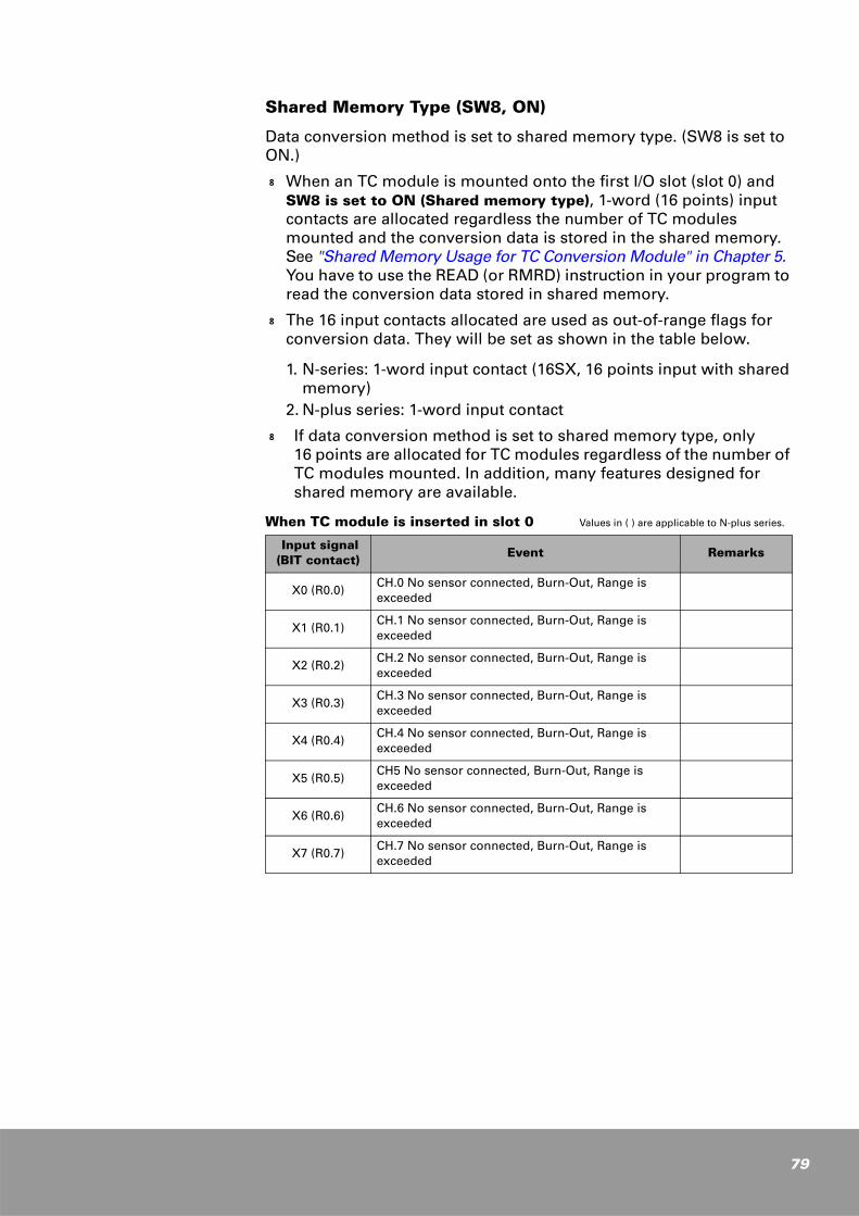
Shared Memory Type (SW8, ON)
Data conversion method is set to shared memory type. (SW8 is set to ON.)
k When an TC module is mounted onto the first I/O slot (slot 0) and SW8 is set to ON (Shared memory type), 1-word (16 points) input contacts are allocated regardless the number of TC modules mounted and the conversion data is stored in the shared memory. See "Shared Memory Usage for TC Conversion Module" in Chapter 5. You have to use the READ (or RMRD) instruction in your program to read the conversion data stored in shared memory.
k The 16 input contacts allocated are used as out-of-range flags for conversion data. They will be set as shown in the table below.
1. N-series: 1-word input contact (16SX, 16 points input with shared memory)
2. N-plus series: 1-word input contact
k If data conversion method is set to shared memory type, only 16 points are allocated for TC modules regardless of the number of TC modules mounted. In addition, many features designed for shared memory are available.
When TC module is inserted in slot 0 Values in ( ) are applicable to N-plus series.
Input signal(BIT contact)
Event Remarks
X0 (R0.0)CH.0 No sensor connected, Burn-Out, Range is exceeded
X1 (R0.1)CH.1 No sensor connected, Burn-Out, Range is exceeded
X2 (R0.2)CH.2 No sensor connected, Burn-Out, Range is exceeded
X3 (R0.3)CH.3 No sensor connected, Burn-Out, Range is exceeded
X4 (R0.4)CH.4 No sensor connected, Burn-Out, Range is exceeded
X5 (R0.5)CH5 No sensor connected, Burn-Out, Range is exceeded
X6 (R0.6)CH.6 No sensor connected, Burn-Out, Range is exceeded
X7 (R0.7)CH.7 No sensor connected, Burn-Out, Range is exceeded
79
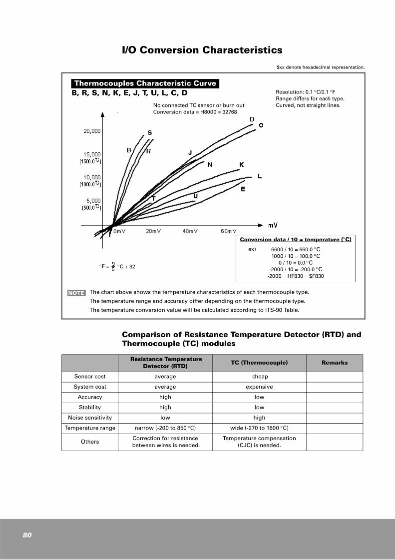
80
I/O Conversion Characteristics
Comparison of Resistance Temperature Detector (RTD) and Thermocouple (TC) modules
The chart above shows the temperature characteristics of each thermocouple type.
The temperature range and accuracy differ depending on the thermocouple type.
The temperature conversion value will be calculated according to ITS-90 Table.
NOTE
Resistance Temperature Detector (RTD)
TC (Thermocouple) Remarks
Sensor cost average cheap
System cost average expensive
Accuracy high low
Stability high low
Noise sensitivity low high
Temperature range narrow (-200 to 850 °C) wide (-270 to 1800 °C)
OthersCorrection for resistance
between wires is needed.Temperature compensation
(CJC) is needed.
B, R, S, N, K, E, J, T, U, L, C, D
No connected TC sensor or burn outConversion data = H8000 = 32768
Resolution: 0.1 °C/0.1 °FRange differs for each type.Curved, not straight lines.
Conversion data / 10 = temperature (°C)
6600 / 10 = 660.0 °C1000 / 10 = 100.0 °C
0 / 10 = 0.0 °C-2000 / 10 = -200.0 °C
-2000 = HF830 = $F830
Thermocouples Characteristic Curve
ex)
$xx denote hexadecimal representation.
°F = 9
− °C + 32 5
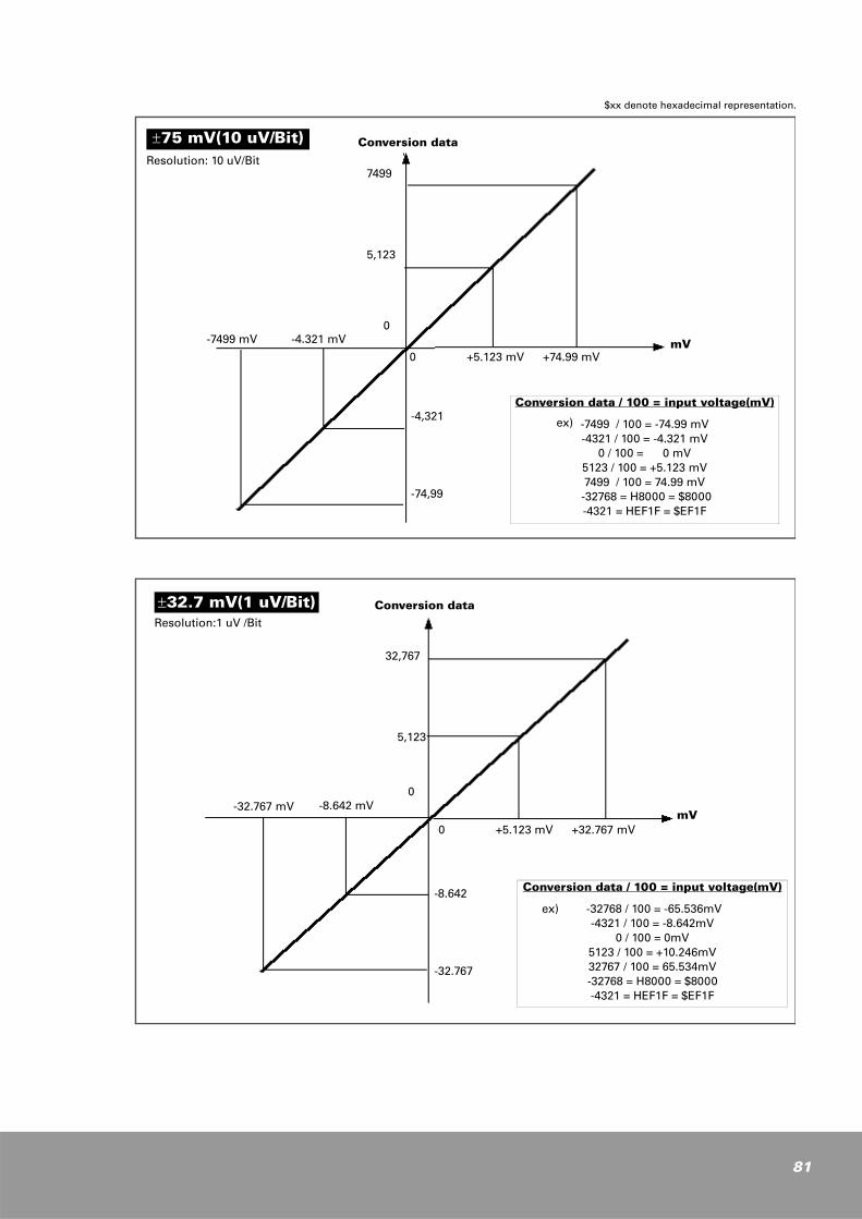
$xx denote hexadecimal representation.
±75 mV(10 uV/Bit)Resolution: 10 uV/Bit
-7499 mV -4.321 mV0
0
5,123
7499
+5.123 mV +74.99 mV
-4,321
-74,99
mV
Conversion data
Conversion data / 100 = input voltage(mV)
-7499 / 100 = -74.99 mV-4321 / 100 = -4.321 mV
0 / 100 = 0 mV5123 / 100 = +5.123 mV7499 / 100 = 74.99 mV
-32768 = H8000 = $8000-4321 = HEF1F = $EF1F
ex)
±32.7 mV(1 uV/Bit)Resolution:1 uV /Bit
-32.767 mV -8.642 mV0
0
5,123
32,767
+5.123 mV +32.767 mV
-8.642
-32.767
Conversion data
Conversion data / 100 = input voltage(mV)
-32768 / 100 = -65.536mV-4321 / 100 = -8.642mV
0 / 100 = 0mV5123 / 100 = +10.246mV32767 / 100 = 65.534mV-32768 = H8000 = $8000-4321 = HEF1F = $EF1F
ex)
mV
81
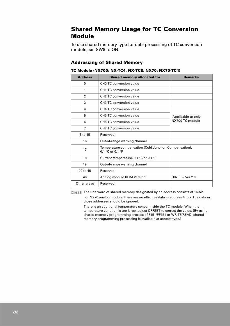
82
Shared Memory Usage for TC Conversion ModuleTo use shared memory type for data processing of TC conversion module, set SW8 to ON.
Addressing of Shared Memory
TC Module (NX700: NX-TC4, NX-TC8, NX70: NX70-TC4)
Address Shared memory allocated for Remarks
0 CH0 TC conversion value
1 CH1 TC conversion value
2 CH2 TC conversion value
3 CH3 TC conversion value
4 CH4 TC conversion value
Applicable to only NX700 TC module
5 CH5 TC conversion value
6 CH6 TC conversion value
7 CH7 TC conversion value
8 to 15 Reserved
16 Out-of-range warning channel
17Temperature compensation (Cold Junction Compensation), 0.1 °C or 0.1 °F
18 Current temperature, 0.1 °C or 0.1 °F
19 Out-of-range warning channel
20 to 45 Reserved
46 Analog module ROM Version H0200 = Ver 2.0
Other areas Reserved
The unit word of shared memory designated by an address consists of 16-bit.
For NX70 analog module, there are no effective data in address 4 to 7. The data in those addresses should be ignored.
There is an additional temperature sensor inside the TC module. When the temperature variation is too large, adjust OFFSET to correct the value. (By using shared memory programming process of F151/PF151 or WRITE/READ, shared memory programming processing is available at contact type.)
NOTE
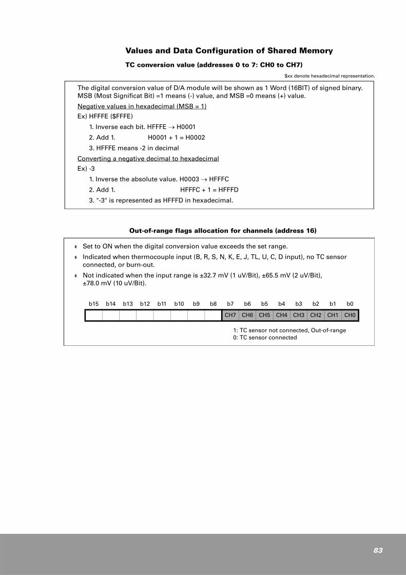
Values and Data Configuration of Shared Memory
TC conversion value (addresses 0 to 7: CH0 to CH7)
$xx denote hexadecimal representation.
Out-of-range flags allocation for channels (address 16)
The digital conversion value of D/A module will be shown as 1 Word (16BIT) of signed binary.MSB (Most Significat Bit) =1 means (-) value, and MSB =0 means (+) value.
Negative values in hexadecimal (MSB = 1)
Ex) HFFFE ($FFFE)
1. Inverse each bit. HFFFE → H0001
2. Add 1. H0001 + 1 = H0002
3. HFFFE means -2 in decimal
Converting a negative decimal to hexadecimal
Ex) -3
1. Inverse the absolute value. H0003 → HFFFC
2. Add 1. HFFFC + 1 = HFFFD
3. "-3" is represented as HFFFD in hexadecimal.
k Set to ON when the digital conversion value exceeds the set range.
k Indicated when thermocouple input (B, R, S, N, K, E, J, TL, U, C, D input), no TC sensor connected, or burn-out.
k Not indicated when the input range is ±32.7 mV (1 uV/Bit), ±65.5 mV (2 uV/Bit), ±78.0 mV (10 uV/Bit).
b15 b14 b13 b12 b11 b10 b9 b8 b7 b6 b5 b4 b3 b2 b1 b0
CH7 CH6 CH5 CH4 CH3 CH2 CH1 CH0
1: TC sensor not connected, Out-of-range0: TC sensor connected
83
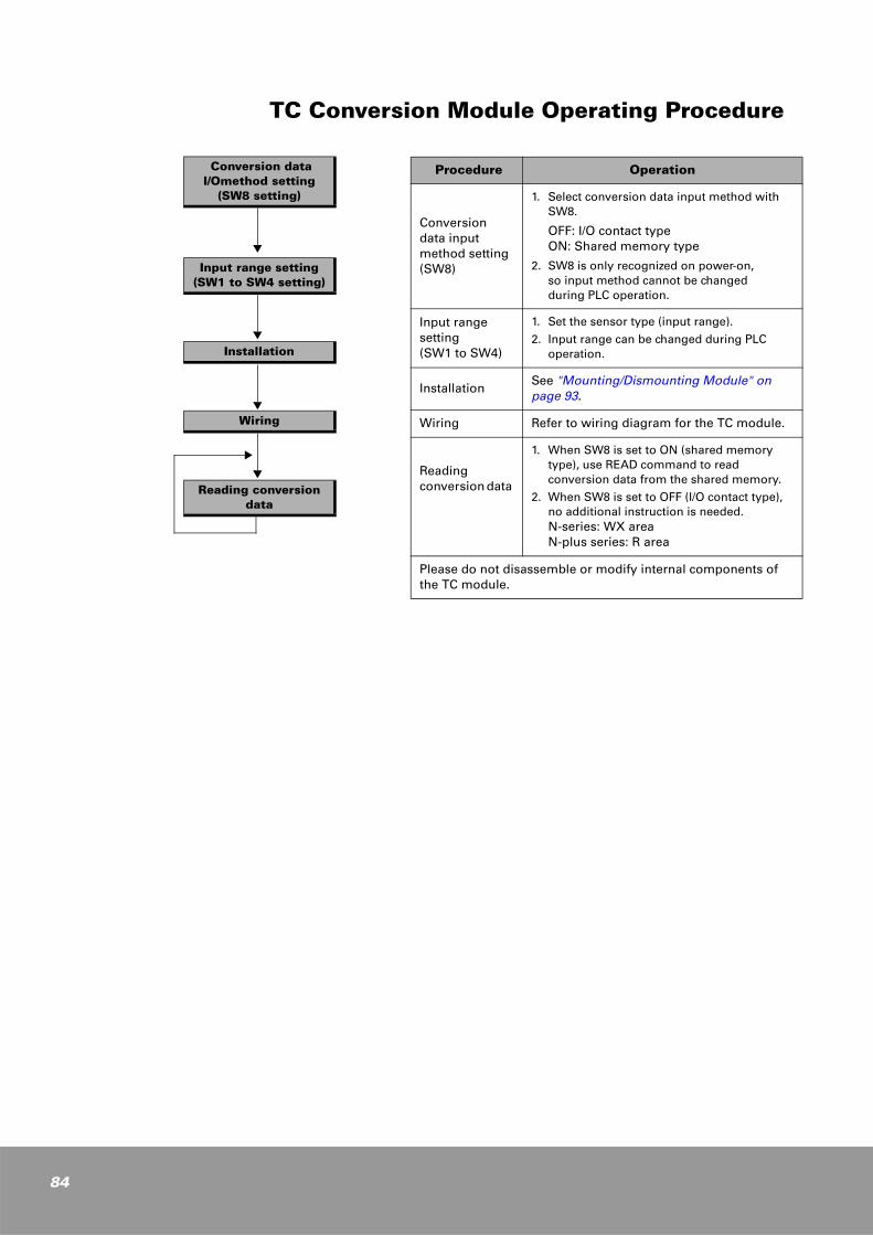
84
TC Conversion Module Operating Procedure
Procedure Operation
Conversion data input method setting(SW8)
1. Select conversion data input method withSW8.
OFF: I/O contact typeON: Shared memory type
2. SW8 is only recognized on power-on, so input method cannot be changed during PLC operation.
Input range setting (SW1 to SW4)
1. Set the sensor type (input range).
2. Input range can be changed during PLCoperation.
InstallationSee "Mounting/Dismounting Module" on page 93.
Wiring Refer to wiring diagram for the TC module.
Reading conversion data
1. When SW8 is set to ON (shared memory type), use READ command to read conversion data from the shared memory.
2. When SW8 is set to OFF (I/O contact type), no additional instruction is needed. N-series: WX area N-plus series: R area
Please do not disassemble or modify internal components of the TC module.
Conversion data I/Omethod setting
(SW8 setting)
Input range setting(SW1 to SW4 setting)
Installation
Wiring
Reading conversiondata
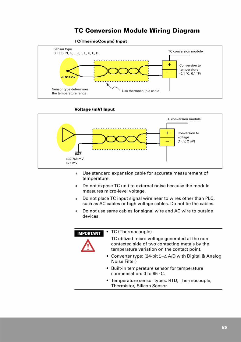
TC Conversion Module Wiring Diagram
TC(ThermoCouple) Input
Voltage (mV) Input
k Use standard expansion cable for accurate measurement of temperature.
k Do not expose TC unit to external noise because the module measures micro-level voltage.
k Do not place TC input signal wire near to wires other than PLC, such as AC cables or high voltage cables. Do not tie the cables.
k Do not use same cables for signal wire and AC wire to outside devices.
TC conversion module
Conversion to temperature (0.1 °C, 0.1 °F)
Use thermocouple cableSensor type determines the temperature range
Sensor typeB, R, S, N, K, E, J, T, L, U, C, D
±32.768 mV±75 mV
Conversion to voltage(1 uV, 2 uV)
TC conversion module
• TC (Thermocouple)
TC utilized micro voltage generated at the non contacted side of two contacting metals by the temperature variation on the contact point.
• Converter type: (24-bit Σ−∆ A/D with Digital & Analog Noise Filter)
• Built-in temperature sensor for temperature compensation: 0 to 85 °C.
• Temperature sensor types: RTD, Thermocouple, Thermistor, Silicon Sensor.
IMPORTANT
85
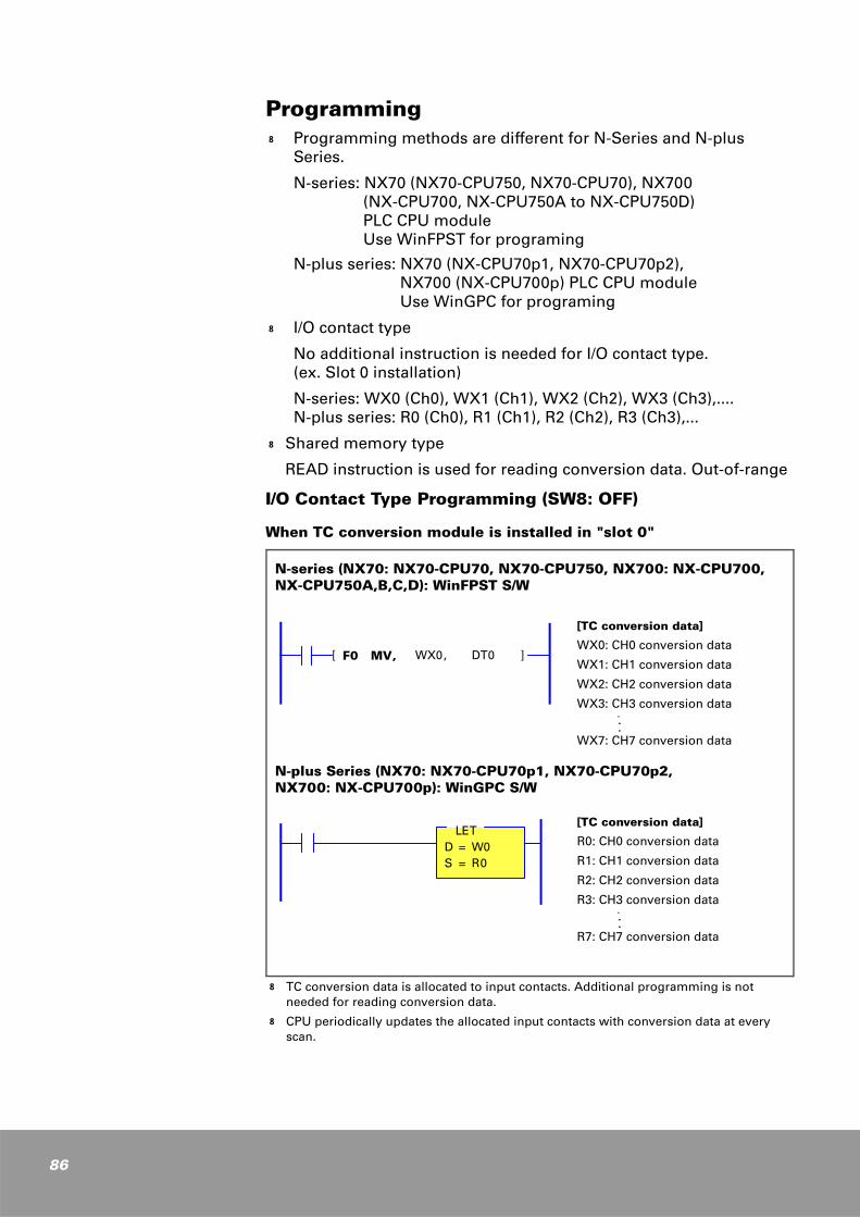
86
Programming
I/O Contact Type Programming (SW8: OFF)
When TC conversion module is installed in "slot 0"
k TC conversion data is allocated to input contacts. Additional programming is not needed for reading conversion data.
k CPU periodically updates the allocated input contacts with conversion data at every scan.
k Programming methods are different for N-Series and N-plus Series.
N-series: NX70 (NX70-CPU750, NX70-CPU70), NX700 (NX-CPU700, NX-CPU750A to NX-CPU750D) PLC CPU module Use WinFPST for programing
N-plus series: NX70 (NX-CPU70p1, NX70-CPU70p2), NX700 (NX-CPU700p) PLC CPU module Use WinGPC for programing
k I/O contact type
No additional instruction is needed for I/O contact type. (ex. Slot 0 installation)
N-series: WX0 (Ch0), WX1 (Ch1), WX2 (Ch2), WX3 (Ch3),....N-plus series: R0 (Ch0), R1 (Ch1), R2 (Ch2), R3 (Ch3),...
k Shared memory type
READ instruction is used for reading conversion data. Out-of-range
N-series (NX70: NX70-CPU70, NX70-CPU750, NX700: NX-CPU700, NX-CPU750A,B,C,D): WinFPST S/W
N-plus Series (NX70: NX70-CPU70p1, NX70-CPU70p2, NX700: NX-CPU700p): WinGPC S/W
[TC conversion data]
WX0: CH0 conversion data
WX1: CH1 conversion data
WX2: CH2 conversion data
WX3: CH3 conversion data ...
WX7: CH7 conversion data
[ F0 MV, WX0, DT0 ]
[TC conversion data]
R0: CH0 conversion data
R1: CH1 conversion data
R2: CH2 conversion data
R3: CH3 conversion data ...
R7: CH7 conversion data
LETD = W0S = R0

Shared memory type of programming (SW8: ON)
Shared Memory instruction - READ
Shared Memory instruction - WRITE
N-series (NX70: NX70-CPU70, NX70-CPU750, NX700: NX-CPU700, NX-CPU750A, B, C, D): WinFPST S/W
N-plus Series (NX70: NX70-CPU70p1, NX70-CPU70p2, NX700: NX-CPU700p): WinGPC S/W
S1: Installation slot number of TC module.
S2: Starting address of shared memory where source data is stored.
n: The number of words of source data to read.
D: Starting address of the destination to store the read data to.
[ F150 READ, S1, S2, n, D ]
TO : Starting address where readdata is stored.
SZ : The number of words of data to read (Size).
FR: Installation slot number of TC module and starting address of shared memory where source data is stored (From).
READTO =SZ =FR =
N-series (NX70: NX70-CPU70, NX70-CPU750, NX700: NX-CPU700, NX-CPU750A,B,C,D): WinFPST S/W
N-plus Series (NX70: NX70-CPU70p1, NX70-CPU70p2, NX700: NX-CPU700p): WinGPC S/W
S1: Installation slot number of TC module.
S2: Starting address of the source data to write to the destination.
n: The number of words of source data to write to the destination.
D: Starting address of the destination in shared memory to which the source data is written.
[ F151 WRT, S1, S2, n, D ]
TO: Installation slot number of TC module and starting address of the destination in shared memory to which the source data is written (To).
SZ: The number of words of source data to write to the destination (Size).
FR: Starting address of the source data to write to the destination (From).
WRITETO =SZ =FR =
87
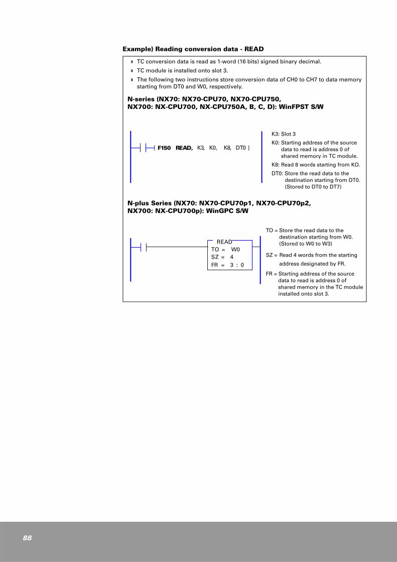
88
Example) Reading conversion data - READ
k TC conversion data is read as 1-word (16 bits) signed binary decimal.
k TC module is installed onto slot 3.
k The following two instructions store conversion data of CH0 to CH7 to data memory starting from DT0 and W0, respectively.
N-series (NX70: NX70-CPU70, NX70-CPU750, NX700: NX-CPU700, NX-CPU750A, B, C, D): WinFPST S/W
N-plus Series (NX70: NX70-CPU70p1, NX70-CPU70p2, NX700: NX-CPU700p): WinGPC S/W
K3: Slot 3
K0: Starting address of the source data to read is address 0 of shared memory in TC module.
K8: Read 8 words starting from KO.
DT0: Store the read data to the destination starting from DT0.(Stored to DT0 to DT7)
[ F150 READ, K3, K0, K8, DT0 ]
TO = Store the read data to the destination starting from W0. (Stored to W0 to W3)
SZ = Read 4 words from the starting
address designated by FR.
FR = Starting address of the source data to read is address 0 of shared memory in the TC module installed onto slot 3.
READTO = W0SZ = 4FR = 3 : 0

6
Product Dimensions and Installation
NX700 PLC Product Dimensions
System Dimensions (mm)
Motherboard Installation Diagram (mm)
111.0
A
B
115.5 118.5
NX-CPU750B
CPU
DCIN
NX-X64D
DCIN
NX-X64D
DCIN
NX-X32D
TROUT
NX-Y32TTR
OUT
NX-Y16T
TROUT
NX-Y16T
TROUT
NX-Y16T
TROUT
NX-Y16T
unit (mm)
Slot TypesDimensions
A B
3-slot type 205.0 184.0
5-slot type 276.0 254.0
8-slot type 381.0 360.0
10-slot type 452.0 430.0
12-slot type 522.0 501.0
¥ı5.0 * 4
L
81.07.0
27.5
22.5
A
unit (mm)
SLOT P L
3-slot type 205.0 153.8
5-slot type 276.0 224.2
8-slot type 381.0 329.8
10-slot type 452.0 400.2
12-slot type 522.0 470.6
89
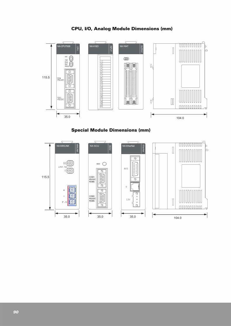
90
CPU, I/O, Analog Module Dimensions (mm)
Special Module Dimensions (mm)
115.5
35.0 104.0INPUT
OUTPUT
NX-CPU750B CPU
NX-X16D NX-Y64T
115.5
35.0 104.0
NX-EtherNet
EtherNet
AUI
T
12V
SCU
NX-SCU
35.0 35.0
+
-
F.G
NX-MWLINK
MWLINK
COM1RS232CRS485
COM2RS232CRS485
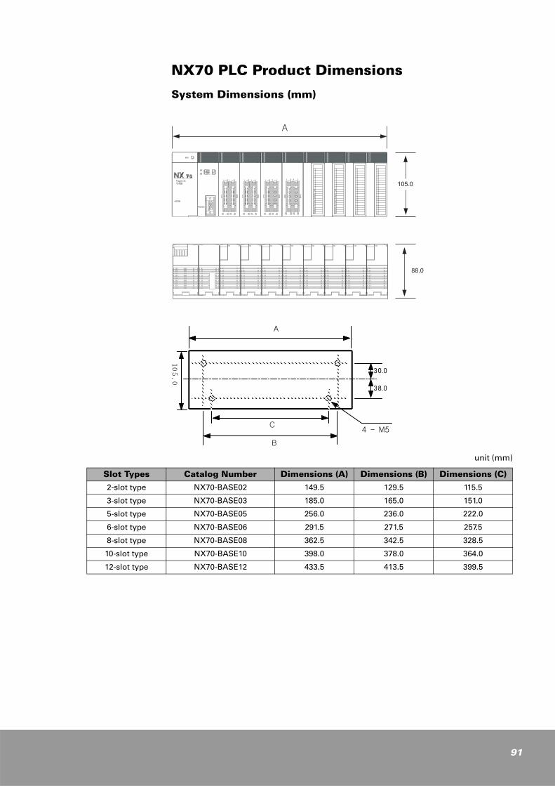
NX70 PLC Product Dimensions
System Dimensions (mm)
unit (mm)
A
B
4 - M5
105.0
30.0
38.0
C
Slot Types Catalog Number Dimensions (A) Dimensions (B) Dimensions (C)
2-slot type NX70-BASE02 149.5 129.5 115.5
3-slot type NX70-BASE03 185.0 165.0 151.0
5-slot type NX70-BASE05 256.0 236.0 222.0
6-slot type NX70-BASE06 291.5 271.5 257.5
8-slot type NX70-BASE08 362.5 342.5 328.5
10-slot type NX70-BASE10 398.0 378.0 364.0
12-slot type NX70-BASE12 433.5 413.5 399.5
91
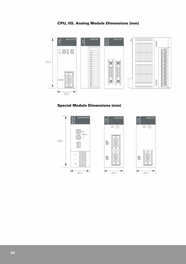
92
CPU, I/O, Analog Module Dimensions (mm)
Special Module Dimensions (mm)
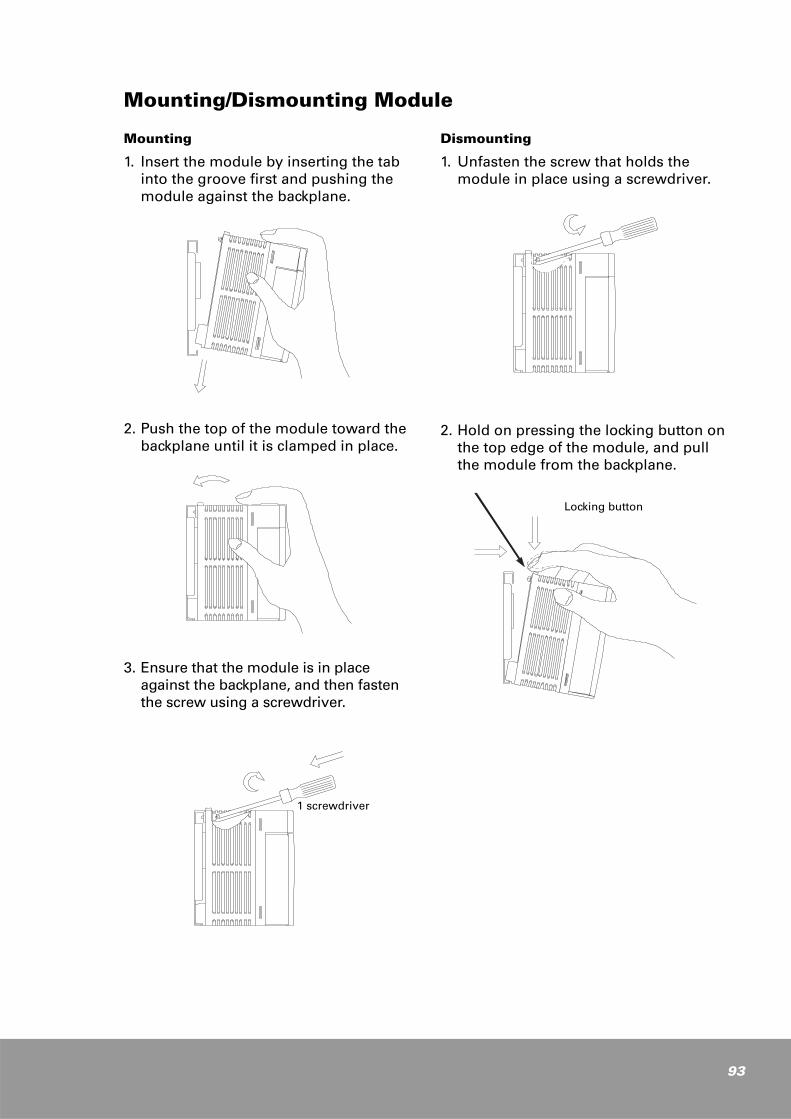
Mounting/Dismounting Module
Mounting
1. Insert the module by inserting the tab into the groove first and pushing the module against the backplane.
2. Push the top of the module toward the backplane until it is clamped in place.
3. Ensure that the module is in place against the backplane, and then fasten the screw using a screwdriver.
Dismounting
1. Unfasten the screw that holds the module in place using a screwdriver.
2. Hold on pressing the locking button on the top edge of the module, and pull the module from the backplane.
1 screwdriver
Locking button
93

94

Publication RSA-NX700-UM013B-EN-P - July 2005 96Supersedes Publication RSA-NX700-UM013A-EN-P - March 2005 Copyright © 2005 Rockwell Samsung Automation. All rights reserved. Printed in Korea.
NX70/NX700 Series Analog Modules (A/D, D/A, RTD, TC) User Manual
Trademarks not belonging to Rockwell Samsung Automation are property of their respective companies.
Rockwell Samsung Automation447-6, Gongse-Ri, Giheung-Eup, Youngin-City,Gyeonggi-Do, South Korea, 449-902Tel: 82-31-280-4700 Fax: 82-31-280-4900
www.samsungautomation.co.kr
Technical Support
Export Sales TeamTel: 82-31-280-4768 Fax: 82-31-280-4900