Embed Size (px)
Citation preview

1
DESCRIPTIONThe Fireye NXCES02 oxygen probe is designed to be used with the PPC4000 and provides continu-ous oxygen concentration readings allowing the PPC4000 to trim the air or fuel servo to obtain opti-mum combustion efficiency. The NXCESO2 offers fast, accurate response and excellent reliabilitywhen mounted in accordance with the guidelines shown.
Along with the oxygen (O2) concentration, the NXCESO2 provides the stack temperature utilizing atype K thermocouple up to 800°F (426°C). On board electronics measure the ambient temperatureand control an integrated cooling fan that is used to maintain the internal temperature between 45°Cand 70°C (113°F to 158°F).
The wide band lambda sensor LSU is a planar ZrO2 (zirconium dioxide) dual cell limiting currentsensor with an integrated heater and pump control. The wide band oxygen sensor responds tochanges in the air/fuel mixture in less than 100 milliseconds. The oxygen sensor cartridge isdesigned to allow for easy replacement without the need to remove the probe from the stack, mini-mizing down time.
The NXCESO2 requires 2 power leads (24 vdc) and a twisted shielded pair for modbus-RTU com-munications. Fireye cable part number 59-565 is suitable for all installations. When connected to thePPC4000, the PPC4000 automatically detects the NXCESO2 through the modbus-RTU communica-tions. The USER INFO screen on the PPC4000 will display the current O2 level, stack temperatureand NXCESO2 status register. To be used as a trim system the NXCESO2 must be commissionedwith the PPC4000. The NXCESO2 can be added to a previously commissioned system without theneed for re-commissioning the servos. That is, the previously commissioned profile setpoints remainvalid. Refer to bulletin PPC-4001 for connection, setup, commissioning and operation information.
The NXCESO2 is available to be used independently. All data pertaining to oxygen concentration,stack temperature, ambient temperature and operational status is available through modbus-RTUcommunications. Local codes having jurisdiction and authority over the use of such instrumentsshould be consulted.
NXCESO2-1001JUNE 6, 2013
NXCESO2OXYGEN PROBE
For Use with PPC4000Parallel Positioning Control
UV1A
UV8A

2
ORDERING INFORMATION
SPECIFICATIONSSupply Voltage: 24VDC
Power Consumption: 12VA
Humidity: 85% RH maximum non-condensing
Temperature Rating: 32°F to 140°F (0°C to +60°C)
Internal Fan Control: On @70°C (158°F), Off @45°C (113°F)
Maximum stack temp: 850°C (1562°F)
Protection Category: NEMA 1 (IP01)
Unit Dimension: see Figure 2 (pg 4)
Shipping Weight:
NXCES02-8 : 8.1lbs (3.67 kg)
NXCES02-16: 9.2 lbs (4.17kg)
NXCES02-30: 11.4 lbs (5.17kg)
Wiring Connections
NXCESO2-8 O2 probe assembly – 8.5 inch (216 mm) insertion depth.NXCESO2-16 O2 probe assembly – 16 inch (407 mm) insertion depth.NXCESO2-30 O2 probe assembly – 30 inch (609 mm) insertion depth.59-565 Cable, contains two power leads, twisted pair and drain wire.NXCESO2P42 Replacement oxygen sensor cartridge for NXCESO2P42 engineering code 01 and aboveNXCESO2P42-1 Replacement oxygen sensor cartridge for NXCESO2P42 engineering code 00 only
35-381-2 Kit, mounting flange, carbon steel. Includes mounting flange, gasket and mounting screws
129-189 Mounting flange cover. Used when flange is mounted in lieu of O2 probe.
FIGURE 1. NXCESO2 INTERNAL PC BOARD NXCESO2 DESCRIPTION 59-565 PPC4000
6 TDB (-) MODBUS - BROWN P12-12
5 TDB (+) MODBUS + ORANGE P12-11
4 N/C - -
3 EARTH DRAIN EARTH
2 DGND RETURN BLACK P2-5
1 +24V POWER RED P2-1
Remove power when servicing
SW1 Provides fault reset and forced calibration
JP1 Baud rate selector. In is 57600 (PPC4000), Out is 19200
JP2 RS485 termination resistor
F1 Heater Fuse 23-2314A, 125V Type LFMX
F2 Input Fuse
EARTH DGND +24 V
SW 1
INPUT
FUSE
HEATER
FUSE
P3
P4
P1
F1
F2
P 2
D1 D2
JP1
D3
TDB-
TDA+
N/C
JP 2
1
Wiring Terminal Blocksee Figure 4
3
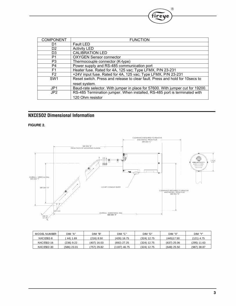
NXCESO2 Dimensional Information
FIGURE 2.
COMPONENT FUNCTIOND1 Fault LEDD2 Activity LEDD3 CALIBRATION LEDP1 OXYGEN Sensor connectorP3 Thermocouple connector (K-type)P4 Power supply and RS-485 communication portF1 Heater fuse. Rated for 4A, 125 vac; Type LFMX, P/N 23-231F2 +24V input fuse. Rated for 4A, 125 vac; Type LFMX, P/N 23-231
SW1 Reset switch. Press and release to clear fault. Press and hold for 10secs to reset system.
JP1 Baud-rate selector. With jumper in place for 57600. With jumper cut for 19200.JP2 RS-485 Termination jumper. When installed, RS-485 port is terminated with
120 Ohm resistor
MODEL NUMBER DIM "A" DIM "B" DIM "C" DIM "D" DIM "X" DIM "Y"NXCES02-8 ( 44) 1.69 (216) 8.50 (426) 16.75 (324) 12.75 (445)17.50 (121) 4.75NXCES02-16 (236) 9.22 (407) 16.03 (692) 27.25 (324) 12.75 (637) 25.06 (295) 11.63NXCES02-30 (586) 23.01 (757) 29.82 (1187) 46.75 (324) 12.75 (648) 25.50 (987) 38.87
4.70119.4
FROM FACE OF MOUNTING FLANGESEE DIM "B"
1.5038.10
SEE DIM "Y" OVERALL VERTICAL DIM
SEE DIM "A"
SEE DIM "D"
CLEARANCE REQUIRED TO REMOVE AND INSTALL. FROM FLUE.
SEE DIM "C"
CLEARANCE REQUIRED TO REMOVE AND INSTALL FROM FLUE .
SEE DIM "X"OVERALL HORIZONTAL DIM
FLUE GAS
1/2 NPT CONDUIT ENTRY

4
Recommended Oxygen Probe Mounting Positions
The O2 probe mounts in the stack using Fireye mounting flange kit 35-381-2. Refer to document133-750 for installation details.
The probe must be mounted in a manner that ensures that the flue gases pass into the gas tube at itsopen end and out of the tube at the flange end. Furthermore, if possible, the flange should be verticalwith the gas tube angled downwards to ensure that particulates do not build up within the sampletube. Probe mounting with the flange horizontal is acceptable. Inverted probe mounting is notacceptable.
OPERATION
The NXCESO2 is powered with 24 vdc supplied from the PPC4000. On systems that contain morethan 4 servos, it is recommended an external 24vdc supply be used for the O2 probe power. TheNXCESO2 contains 3 LED's located on its circuit board. These LED's indicate normal activity(blinking), fault, and calibration completed. The calibration completed LED will remain illuminateduntil the next power cycle.
The NXCESO2 reads the oxygen sensor 3 times per second and the stack temperature and ambienttemperature 1 time every second. This means for each 1 second interval there are 3 oxygen concen-tration readings, 1 stack temperature reading and 1 ambient temperature reading. The remaining timeis used to service modbus-RTU requests, monitor the internal power supply voltages, monitor theintegrity of the stack temperature, ambient temperature and oxygen sensor devices, execute internaldiagnostic tests on the CPU including ram tests, I/O tests, and program memory CRC tests, and tomonitor the internal temperature that will force the internal fan on and off as necessary. Any errorsare reported in the status register and transmitted via modbus to the host.
The wideband flue gas oxygen sensor consists of two parts: a Nernst reference cell and an oxygenpump cell, co-existing in a package that contains a reference chamber and heater element (used toregulate the temperature of the Nernst/pump).
O2 PROBE MOUNTED NOTE ORIENTATION RELATIVE TO FLUE GAS FLOW
FLUE GAS FLUE GASSIDE VIEW
VERTICAL FLUEPROBE MOUNTED ON SIDE 1
30°
FLUE GAS
FLUE GAS
SIDE VIEW
O2 PROBE MOUNTED NOTE ORIENTATION RELATIVE TO FLUE GAS FLOW
CLCLFLUEFLUE
TOP VIEW
SIDE VIEW
FLUE GAS FLUE GAS
CL
3
FLUE GAS
FLUE GAS
TOP VIEW
CLFLUE FLUE
FLUE GAS
SIDE VIEW
O2 PROBE MOUNTED NOTE ORIENTATION RELATIVE TO FLUE GAS FLOW
HORIZONTAL FLUEPROBE MOUNTED ON SIDE
2
HORIZONTAL FLUEPROBE MOUNTED UNDERNEATH
4HORIZONTAL FLUE
PROBE MOUNTED ON TOP
5
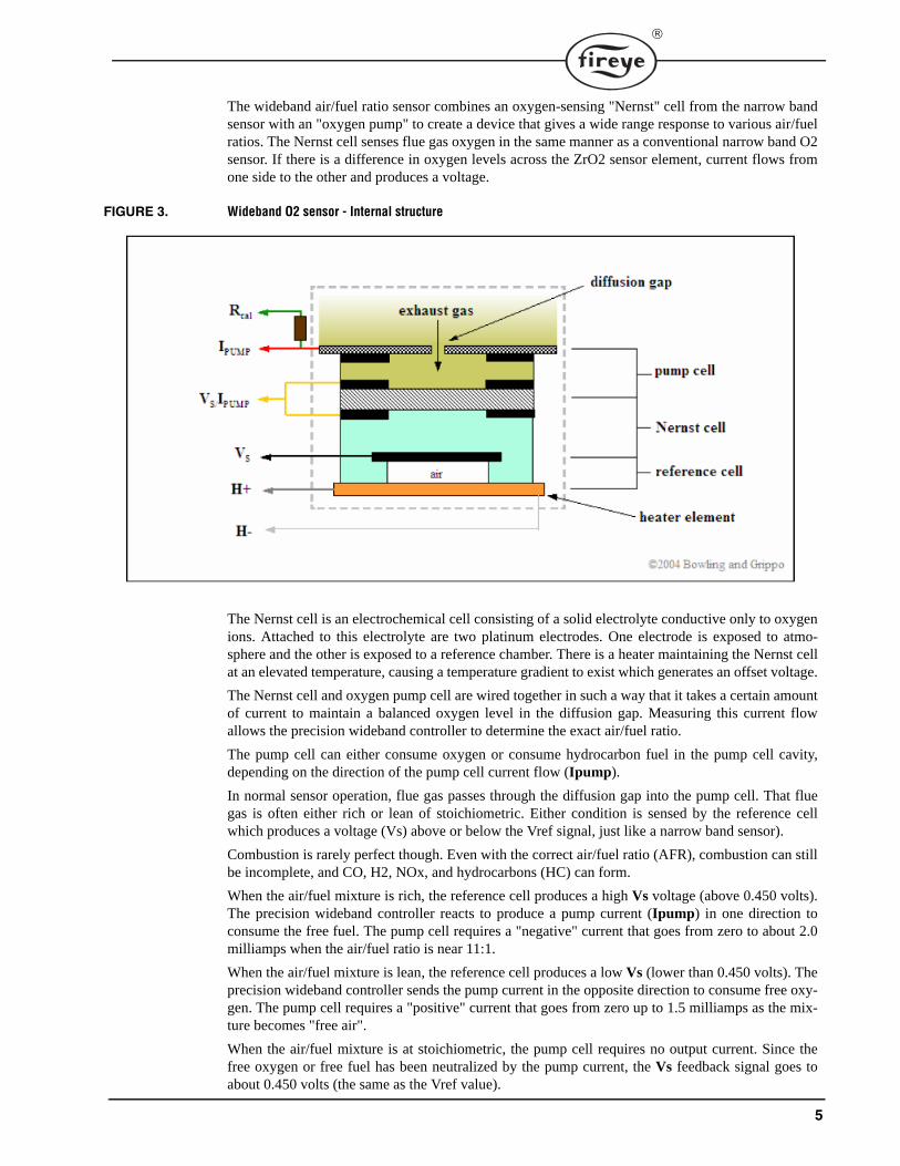
The wideband air/fuel ratio sensor combines an oxygen-sensing "Nernst" cell from the narrow bandsensor with an "oxygen pump" to create a device that gives a wide range response to various air/fuelratios. The Nernst cell senses flue gas oxygen in the same manner as a conventional narrow band O2sensor. If there is a difference in oxygen levels across the ZrO2 sensor element, current flows fromone side to the other and produces a voltage.
FIGURE 3. Wideband O2 sensor - Internal structure
The Nernst cell is an electrochemical cell consisting of a solid electrolyte conductive only to oxygenions. Attached to this electrolyte are two platinum electrodes. One electrode is exposed to atmo-sphere and the other is exposed to a reference chamber. There is a heater maintaining the Nernst cellat an elevated temperature, causing a temperature gradient to exist which generates an offset voltage.
The Nernst cell and oxygen pump cell are wired together in such a way that it takes a certain amountof current to maintain a balanced oxygen level in the diffusion gap. Measuring this current flowallows the precision wideband controller to determine the exact air/fuel ratio.
The pump cell can either consume oxygen or consume hydrocarbon fuel in the pump cell cavity,depending on the direction of the pump cell current flow (Ipump).
In normal sensor operation, flue gas passes through the diffusion gap into the pump cell. That fluegas is often either rich or lean of stoichiometric. Either condition is sensed by the reference cellwhich produces a voltage (Vs) above or below the Vref signal, just like a narrow band sensor).
Combustion is rarely perfect though. Even with the correct air/fuel ratio (AFR), combustion can stillbe incomplete, and CO, H2, NOx, and hydrocarbons (HC) can form.
When the air/fuel mixture is rich, the reference cell produces a high Vs voltage (above 0.450 volts).The precision wideband controller reacts to produce a pump current (Ipump) in one direction toconsume the free fuel. The pump cell requires a "negative" current that goes from zero to about 2.0milliamps when the air/fuel ratio is near 11:1.
When the air/fuel mixture is lean, the reference cell produces a low Vs (lower than 0.450 volts). Theprecision wideband controller sends the pump current in the opposite direction to consume free oxy-gen. The pump cell requires a "positive" current that goes from zero up to 1.5 milliamps as the mix-ture becomes "free air".
When the air/fuel mixture is at stoichiometric, the pump cell requires no output current. Since thefree oxygen or free fuel has been neutralized by the pump current, the Vs feedback signal goes toabout 0.450 volts (the same as the Vref value).
6
To sense a wide range of air/fuel ratios, the oxygen pump uses a heated cathode and anode to pullsome oxygen from the flue into a "diffusion" gap between the two components. The pump is drivenby two PWM or processor ports in opposite polarity (using either a H-bridge setup or direct proces-sor port drive), and the precision wideband controller measures the time when the reference cellpasses through 0.45 volts. It can then adjust the PWM timing to bracket this 0.45 volt stoichiometricflipping point.
Like a conventional narrow band sensor, the precision wideband controller circuit produces a low-voltage signal when the air/fuel ratio goes lean, and a high-voltage signal when the mixture is rich.But instead of switching abruptly at stoichiometric, it produces a proportional change in the voltage.It increases or decreases in proportion to the relative richness or leanness of the air/fuel ratio. With astoichiometric air/fuel ratio, the wide-band O2 sensor will produce a steady 0.450 volts. If the mix-ture goes a little richer or a little leaner, the sensor's output voltage will only change a small amountinstead of rising or dropping dramatically.
The result is a sensor element that can precisely measure air/fuel ratios (AFR) from very rich (10:1)to extremely lean (free air).
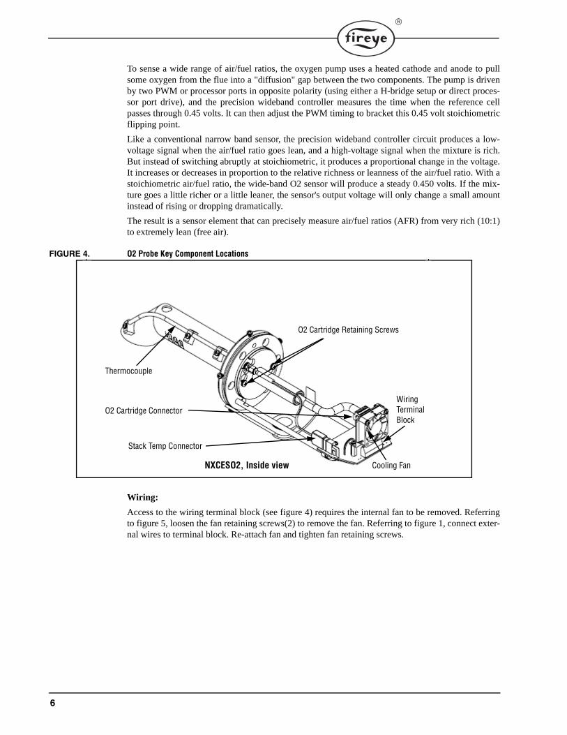
FIGURE 4. O2 Probe Key Component Locations
Wiring:
Access to the wiring terminal block (see figure 4) requires the internal fan to be removed. Referringto figure 5, loosen the fan retaining screws(2) to remove the fan. Referring to figure 1, connect exter-nal wires to terminal block. Re-attach fan and tighten fan retaining screws.
O2 Cartridge Retaining Screws
Thermocouple
Cooling Fan
O2 Cartridge Connector
Stack Temp Connector
NXCESO2, Inside view
WiringTerminalBlock

7
FIGURE 5. Flue Gas Flow through Probe
Replacement O2 Cartridge
FIGURE 6. NXCES02P42 Replacement Cartridges
To replace the cartridge the following steps are recommended:
1.Remove power from the O2 probe and allow O2 sensor heat to cool.2.Remove outside cover from O2 probe and set aside.
a.Loosen but do not remove the thumb screws and slide cover to rear and off. [At this time, if necessary, power to the probe can be disconnected at the terminal strip, pin 1]. The O2 probe should resemble the following:
Flue Gas Exit Direction
Flue Gas Inlet Direction
Fan Retaining Screws
Cartridge Retaining Screws
O2 Sensing Cartridge, NXCESP42
NOTE: Fireye has made various improvements to the NXCESO2 oxygen probe. Among the improvements is the connector on the end of the replacement cartridge and the mating shell located on the printed circuit board. The engineering code located on the cartridge unit label, shown below, can be used to determine which replacement cartridge is required. NXCESO2P42-1 can be used only with code 00 cartridges. NXCESO2P42replacement cartridges can be used to replace all other units with engineering code 01 and higher
6 pin connector 5 pin connector
Unit Label
NXCESO2P42NXCESO2P42-1
8
3.Locate the connector end of the O2 cartridge and remove from shell located on O2 printed circuit board.
4.Unplug fan connector located on O2 printed circuit board.5.Loosen and remove fan retaining screws (2) to remove fan and set aside.6.Loosen but do not remove O2 cartridge retaining screws (2).7.Rotate O2 cartridge counter-clockwise and withdraw from O2 probe flue pipe..8.Insert replacement cartridge into flue pipe passed retaining screws and rotate clockwise to seat
properly.9.Tighten screws to secure cartridge in place.10.Attach 5 pin connector on replacement cartridge to O2 printed circuit board.11.Re-install cooling fan to mounting standoffs and secure with 2 screws.12.Plug in fan connector to O2 printed circuit board.13.Install O2 probe cover and secure with thumb screws.
14.Apply power to system or O2 probe.
Operator Push Button, SW1
Referring back to Figure 1, the Operator Push Button, SW1 provides the installer\technician with theability to reset the Oxygen Probe, perform an Oxygen Calibration, or clear the Fault LED, D1. TheActivity LED, D2, is used as feedback to indicate to the installer\technician the status of the SW1timing for the desired function.
Manual Reset
If the Operator Push Button, SW1, is pressed after the Oxygen Probe has completed the power on orreset cycle (Oxygen Probe is in normal operation and Activity LED, D2, is blinking) then the Activ-ity LED will begin cycling on and off in half second intervals for five seconds or until the OperatorPush Button is released. If SW1 is held depressed through the five second interval, then the ActivityLED will turn on (not blink) indicating to the user that a release of SW1 will initiate an OxygenProbe Reset.
Fault LED Clear
If the Oxygen Probe is in normal operation with the Activity LED, D2, blinking, a press and releaseof the Operator Push Button, SW1, before the five second interval has completed then the FaultLED, D1, will be cleared.
Manual Calibration
With the NXCESO2 probe connected to the PPC4000, it is strongly recommended that calibration beperformed through the NXD410 User Interface.
Manual Calibration should only be performed while there is clean air (no stack gases) flowingthrough the Oxygen Probe sensor. If the Operator Push Button is pressed during a power cycle orafter a Manual Reset, then the Activity LED will begin cycling on and off in half second intervals forfive seconds or until the Operator Push Button is released. If SW1 is held through the five secondinterval, then the Activity LED will turn on steady indicating to the user that a release of the Opera-tor Push Button will initiate an Oxygen Calibration.
Care must be taken that if the Manual Calibration is performed after a Manual Reset, then immedi-ately after releasing the button to start the reset, the button has to be pressed again before the resetprocess has finished. This has to be within a quarter second from button release to button press. Therest of the procedure must be fallowed as described above.

9
Modbus memory map
The probe data is accessed using the modbus-RTU "Holding Register Read" request function (03).A single value can be read by performing a modbus holding register read request on only one of theregisters by using the register address and a register count of one. The values of a series of adjacentregisters can be accessed by using the address of the desired starting register and a count of the num-ber of subsequent registers to read.
The modbus address of the O2 probe is fixed at 11 (0xB).
The baud rate with JP1 in is 57600 baud.
The baud rate with JP1 cut is 19200 baud.
Register Number Register DescriptionHolding
register
Message
address
(Hex)40001 (0x00) Probe Status40002 (0x01) Stack Temperature40003 (0x02) Ambient Temperature40004 (0x03) Extended O2 Reading40005 (0x04) CO Expansion[0]40006 (0x05) CO Expansion[1]40007 (0x06) CO Expansion[2]40008 (0x07) CO Expansion[3]40009 (0x08) CO Expansion[4]40010 (0x09) CO Expansion[5]40011 (0x0A) Probe Firmware Rev40012 (0x0B) Probe ROM CRC40013 (0x0C) Stack Temperature Maximum Limit Configuration40014 (0x0D) Ambient Temperature Upper Limit Configuration40015 (0x0E) Ambient Temperature Lower Limit Configuration40016 (0x0F) Last Fault History Type40017 (0x10) Last Fault History Data40018 (0x11) 2nd to Last Fault History Type40019 (0x12) 2nd to Last Fault History Data40020 (0x13) 3rd to Last Fault History Type40021 (0x14) 3rd to Last Fault History Data40022 (0x15) 4th to Last Fault History Type40023 (0x16) 4th to Last Fault History Data40024 (0x17) 5th to Last Fault History Type40025 (0x18) 5th to Last Fault History Data40026 (0x19) 6th to Last Fault History Type40027 (0x1A) 6th to Last Fault History Data40028 (0x1B) 7th to Last Fault History Type40029 (0x1C) 7th to Last Fault History Data40030 (0x1D) 8th to Last Fault History Type40031 (0x1E) 8th to Last Fault History Data40032 (0x1F) 9th to Last Fault History Type40033 (0x20) 9th to Last Fault History Data40034 (0x21) 10th to Last Fault History Type40035 (0x22) 10th to Last Fault History Data40036 (0x23) Lambda (Disabled – when enabled value is supplied when Lambda < 8.512)40037 (0x24) Standard O2 (Disabled - when enabled value is supplied when Lambda ≥ 8.512)40038 (0x25) Battery Voltage (Disabled)

10
Probe Status Register
When reading the status register, the values are representative of a compound value and have the fol-lowing bit definitions…
Status Register Bit Positions
15 14 13 12 11 10 9 8 7 6 5 4 3 2 1 0Stack Ambient CPU Sensor Status BitsBits Value Latched Valid O2 Description
Bits 15-14 0 (b00) N/A Yes Stack Probe OK1 (b01) No Yes Stack Probe Disconnected Fault2 (b10) No Yes Stack Over Temperature Fault (default 900 ºF)3 (b11) No Yes Stack Read Fault (Temperature is at 0 degrees C)
Bits 13-12 0 (b00) N/A Yes Ambient Temperature OK1 (b01) No No Ambient Temperature Cannot Be Read Fault2 (b10) No No Ambient Over Temperature Fault3 (b11) No No Ambient Under Temperature Fault
Bits 11-8 0 (b0000) N/A Yes CPU OK1 (b0001) Yes No CPU CRC Fault2 (b0010) Yes No CPU RAM Fault3 (b0011) Yes No CPU Instruction Fault
Bits 7-0 0 (0x00) N/A Yes Sensor OK1 (0x01) No No Sensor 24 Volt Low Fault (not valid on older hdwr)2 (0x02) No No Sensor 24 Volt High Fault (not valid on older hdwr)3 (0x03) No No Sensor 12 Volt Open Fault (not valid on older hdwr)4 (0x04) No No Sensor 12 Volt Low Fault (not valid on older hdwr)5 (0x05) No No Sensor 12 Volt High Fault (not valid on older hdwr)6 (0x06) Yes No Sensor Unexpected Calibration Fault7 (0x07) Yes No Sensor Stuck Fault (Warm Up, Calibration, etc)8 (0x08) Yes No Sensor Calibration Needed9 (0x09) No No Sensor Heater Short Fault
10 (0x0A) No No Sensor Heater Open Fault11 (0x0B) No No Sensor Pump Short Fault12 (0x0C) No No Sensor Pump Open Fault13 (0x0D) No No Sensor Nernst Cell Short Fault14 (0x0E) No No Sensor Nernst Cell Open Fault15 (0x0F) No No Sensor Conversion Timeout Fault16 (0x10) No No Sensor Low Voltage Fault17 (0x11) No No Sensor Too Cold Fault18 (0x12) No No Sensor Too Hot Fault19 (0x13) No No Sensor Air Calibrating20 (0x14) No No Sensor Heater Calibrating21 (0x15) No No Sensor Comm. Busy22 (0x16) No No Sensor Comm. Fault32 (0x20) No No Sensor Warming Up33 (0x21) No No Sensor in standby

11
Probe Status Register Write
The Probe Status Register is also used to perform functions that modify the state of the O2 Probe.This is accomplished by writing a specific value to the status register using the Modbus Write Hold-ing Register function (function code 06).
Probe Status Register Calibrate
A sensor calibration is performed when the value 0xCACA (51914 decimal) is written to the statusregister. Note: This should be issued only when there is free air available.
Probe Status Register Standby On/Off
The sensor is placed into standby mode when the value 0xF0F0 (61680 decimal) is written to the sta-tus register. The sensor is taken out of standby by a system reset (User Button), a power cycle, or bywriting the value 0x0F0F (3855 decimal) to the register.
Note: When the sensor is placed into standby, the sensor status bits of the status register will indicatethe condition unless the register currently contains a higher priority fault.
Probe Status Register Fault LED Clear
If there is a new O2 Probe fault, Fault LED will be turned on. A clear fault is performed when thevalue 0xA5A5 (42405 decimal) is written to the status register. Clearing the fault only resets theFault LED and does not clear the status register nor does it reset the Fault History.
Stack Temperature Register
The stack temperature is read via the probes thermocouple and has a range from 0 to 1024°C (32 to1875°F ). This Modbus register data is refreshed every second. The register data requires conver-sion as shown in the following equation…
Ambient Temperature Register
The ambient temperature (to the sensor board) is read via the probes Ambient Temperature Modulethat has a range from -55 to 125°C (-67 to 257°F ). This Modbus register data is refreshed every sec-ond. The register data is a 2's compliment number and requires conversion as shown in the follow-ing equation…
Extended O2 Register
The Extended O2 Register is the direct 2's compliment value supplied by the sensor module whenthe status registers bits 8 to 11 is equal to 4. This Modbus register data is refreshed every 333 milli-seconds. The register data requires conversion as shown in the following equation…
CO Expansion Registers
These registers are reserved for future use.
Probe Firmware Revision Register
The Probe Firmware Revision Register contains 2 bytes where the upper byte is the major revisionnumber and the lower byte is the minor revision number. Both values are expressed as ASCII valuesand are, for unreleased versions, in the range of "A" to "Z" for the major revision number and "a" to
Temp(°C) =Register Value
4(decimal)
Temp(°C) =Register Value
16(decimal)
Oxygen(%) =Register Value100(decimal)

12
"z" for the minor revision number. Released versions of the firmware have the major and minor revi-sion number range of "0" to "9".
Probe CRC Register
The Probe CRC Register contains the stored CRC value of the code space. This is the value that isdetermined at build time and stored in a protected portion of the ROM space. If a CRC error isdetected (the run time CRC calculation of the code space does not match the stored CRC value), thenthe fault history is updated with a CRC error containing the calculated CRC value so that a faultdetermination can be made.
Stack Temp Max Limit Config Register
The stack temperature, under normal conditions, has a range of 0 to 1024°C (32 to 1875°F ). TheStack Temperature Limit Configuration register configures the upper limit alarm setting for the stackbits of the status register. The configured value can be changed by performing a "Holding RegisterWrite" to the register. The default limit is 482°C (900°F ). The allowed settings of this register arefrom 38 to 1024°C (100 to 1875°F ). The register data requires conversion as shown in the followingequation…
Register ValueUpper Limit = Upper Limit Temp (°C) * 4(decimal)
Ambient Temp Upper Limit Config Register
The ambient temperature, under normal conditions, has a range of -55 to 125°C (-67 to 257°F ). TheAmbient Temperature Upper Limit Configuration register configures the upper limit alarm settingfor the ambient bits of the status register. The configured value can be changed by performing a"Holding Register Write" to the register. The default limit is 85°C (185°F ). The allowed settings ofthis register are from 65 to 125°C (149 to 257°F ). The register data requires conversion as shown inthe following equation…
Register ValueUpper Limit = Upper Limit Temp (°C) * 16(decimal)
Ambient Temp Lower Limit Config Register
The Ambient Temperature Lower Limit Configuration register, as with the Ambient TemperatureUpper Limit Configuration register configures the lower limit alarm setting for the ambient bits ofthe status register. The configured value can be changed by performing a "Holding Register Write"to the register. The default limit is -25°C (-13°F ). The allowed settings of this register are from -15to -55°C (5 to -67°F ). The register data requires conversion as shown in the following equation…
Register ValueLower Limit = Lower Limit Temp (°C) * 16(decimal)
Fault History Registers
The Fault history is made up of the last ten recorded faults. Each record uses two registers and theregisters are updated when the fault is detected. The first register in each record is a compound reg-ister and has the following bit definitions…
The second register can contain the data that was tested to determine that the fault occurred and isdefined by the type of the detected fault.
Fault History ID Register Bit Positions15 14 13 12 11 10 9 8 7 6 5 4 3 2 1 0
Fault Module Bits Fault Type Bits Fault Sub Type Bits
Fault History Data Register Bits15 14 13 12 11 10 9 8 7 6 5 4 3 2 1 0
Fault Data Bits

13
The following table describes the purpose of each bit in each fault history record comprised of thefault history ID register and the fault history data register (all values are in hexadecimal)…
Fault History ID Register Fault History Data Register
Bits (0-15)
Fault Module
Bits (12-15)
Fault Type
Bits (8-11)
Fault Sub Type
Bits (0-7)1 (CPU) 0 (ROM CRC) N/A Calculated CRC
1 (Data Overwrite) N/A Test Reg 0, Test Reg 12 (RAM) RAM XOR test position RAM test position3 (Instruction) N/A Test Reg 0, Test Reg 14 (State) Current state N/A5 (Reset) Reset State 0x01 (HW Reset) Vdd Monitor State
Reset State 0x02 (Vdd Reset)Reset State 0x04 (Missed Clk)Reset State 0x08 (Watchdog)Reset State 0x10 (SFW Reset)Reset State 0x20 (CMP Reset)Reset State 0x40 (Flash Err)
2 (Stack Temp) 0 (Disconnect) N/A Stack Temp Data1 (Over Heat)2 (Low Temp)3 (Comms)
3 (Ambient Temp) 0 (No Convert) N/A Ambient Temp Data1 (Overheat)2 (Low Temp)3 (Comms)
4 (O2 Sensor) 0 (Sensor Device) 1 (Heater Short) Sensor Data2 (Heater Open)3 (Pump Cell Short)4 (Pump Cell Open)5 (Nernst Cell Short)6 (Nernst Cell Open)8 (Sensor Time Out)9 (Low Voltage)A (Cold Sensor)B (Sensor Overheat)
1 (Comms) 0 (Mode Query) Sensor Data1 (Mode Read)2 (Mode Set)3 (Read O2)4 (Read Lambda)5 (Read Battery Voltage)6 (Cal Command)7 (Cal Progress)
8 (Read Error)
2 (Operations) 0 (Unexpected Cal) Sensor Data1 (Cal Needed)
5 (Internal Comm) 0 (Comm Busy) 0 (Stack Device)1 (Ambient Device)2 (O2 Device)3 (Data Store Device)
Config, Control Register1 (Comm Collision)2 (Dev Not Ready)
6 (ModBus) 0 (Min size error) Last received byte Buffer size (bytes)1 (Max size error) Last received byte Buffer size (bytes)2 (CRC error) Buffer size (bytes) Calculated CRC3 (Comm Timeout) ModBus State Failed Fault Type Store
14
NOTICEWhen Fireye products are combined with equipment manufactured by others and/or integrated intosystems designed or manufactured by others, the Fireye warranty, as stated in its General Terms andConditions of Sale, pertains only to the Fireye products and not to any other equipment or to thecombined system or its overall performance.
WARRANTIESFIREYE guarantees for one year from the date of installation or 18 months from date of manufactureof its products to replace, or, at its option, to repair any product or part thereof (except lamps, elec-tronic tubes and photocells) which is found defective in material or workmanship or which otherwisefails to conform to the description of the product on the face of its sales order. THE FOREGOINGIS IN LIEU OF ALL OTHER WARRANTIES AND FIREYE MAKES NO WARRANTY OFMERCHANTABILITY OR ANY OTHER WARRANTY, EXPRESS OR IMPLIED. Except asspecifically stated in these general terms and conditions of sale, remedies with respect to any productor part number manufactured or sold by Fireye shall be limited exclusively to the right to replace-ment or repair as above provided. In no event shall Fireye be liable for consequential or special dam-ages of any nature that may arise in connection with such product or part.
FIREYE NXCESO2-10013 Manchester Road JUNE 6, 2013Derry, New Hampshire 03038 USA Supersedes October 20, 2011www.Fireye.com