Embed Size (px)
Citation preview
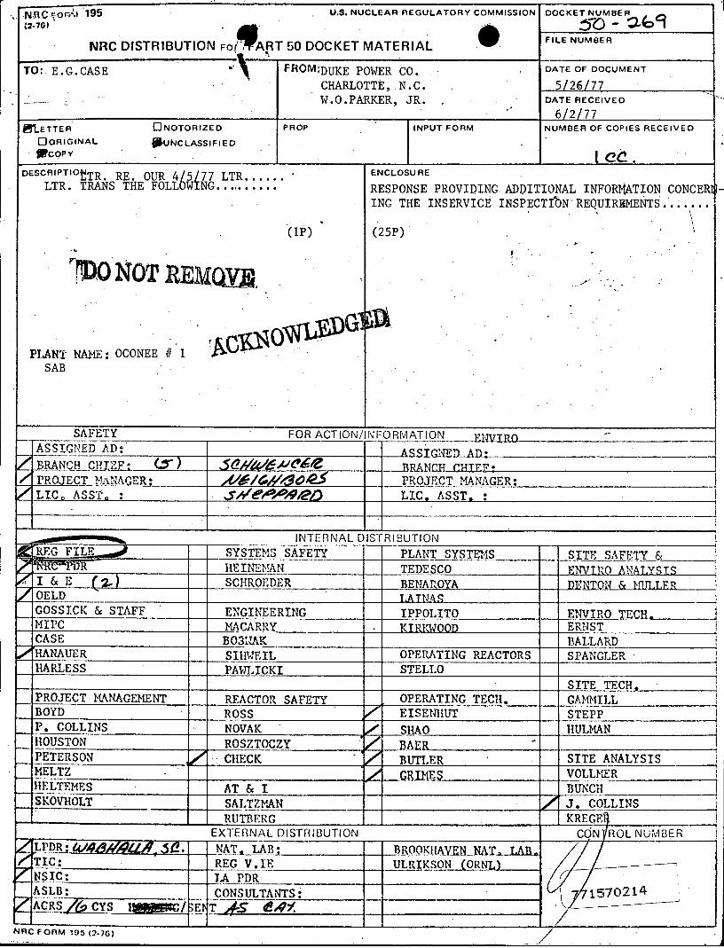
N.AC POW.I 195 U.S. NUCLEAR REGULATORY COMMISSION DOCKET NUMBER
(2-76) .- 01 NRC DISTRIBUTION For ART 50 DOCKET MATERIAL FILE NUMEA
TO: E.G.CASE * FROM:DUKE POWER CO.. . DATE OF DOCUMENT
CHARLOTTE, N.C. 5/26/77 W.O.PARKER, JR. . DATE RECEIVED
6/2/77
OnETTER . ONOTORIZED PROP INPUT FORM NUMBER OF COPIES RECEIVED
OORIGINAL #UNCLASSIFIED fpcory
DESCRIPTIOtTR. RE. OUR 4/5/77 LTR.... E RE. 45177ENCLOSURE
LTR. TRANS THE FOLLOWIG RESPONSE PROVIDING ADDITIONAL INFORMATION CONCERH
ING THE INSERVICE INSPECTIbN-REQUIREMENTS.......
(1p) (25P)
riDO NOT REM y
PLANT NAME: OCONEE #I 1 SAB
SAFETY FOR ACTIO NFORMATION ___,____
ASSIGNED AD: A 5__SSTNE_ __A- _ - _,RAN _ _____ &T____ 5a___wfve____xz___
r BRANCHILCIEi* _ PROJECT MANAGER: _____4 _______ PROJECT MANAGER:
LIC, ASST, i _a____p___ LIC, ASST, :
INTERNAL DISTRIBUTION RU.G FlL SYSTEMS SAFETY PLANT SYSTEMS SITE SAFET &
HEINEMAN TEDESCO ENVTRO ANALYSIS I & E (2) SCHROEDER BENAROYA DNTON & MTLLER OELD .ATNAS GOSSICK & STAFF ENGINEERING IPPOLITO ENVIROTECH
_MIPC MACARRY KTEKWOOD ERNST CASE BO3MAK BALLARD
_ HANAUER SIIIWEIL OPERATING REACTORS SPANGLER HARLESS PAWLICKI STELLO
SITE TECH,
PROJECT MANAGEMENT REACTOR SAFETY OPERATING TECH. GAMMILL BOYD ROSS EISENH1UT STEPP P. COLLINS NOVAK SHAO HULMAN HOUSTON ROSZTOCZY __BAER PETERSON 0 CHECK BUTLER SITE ANALYSIS MELTZ I / GRIMES VOLLMER
HELTEMES AT & I BUNCH
SKOVROLT SALTZMAN z4 J. COLLINS
RUTBERC I KREGE
EXTERNAL DISTRIBUTION CON ROL NUMBER
/'LPDR;&$ _ NAT.1AB: BROOKHANVEN NAL, TAB t TIC: -REG V.IE ULRIKSON (ORNL)
_ NSIC: _ TA PDR
ASLB: CONSULTANTS: 1570214
2 ACRS FALCYS Iggc/ENT , d4 BX:/
NRC FORM 195 (2.76)
DUKE POWER COMPANY
POWER BU .DING
422 Sour CRURcH STREET, GRARLOTTE, N. G. 28242
WILLIAM 0. PARKERJR. May 26, 1977 VtC:E PRESIENT T LEPoN:ARA 70
STEAM -PRODUCTION 3734033
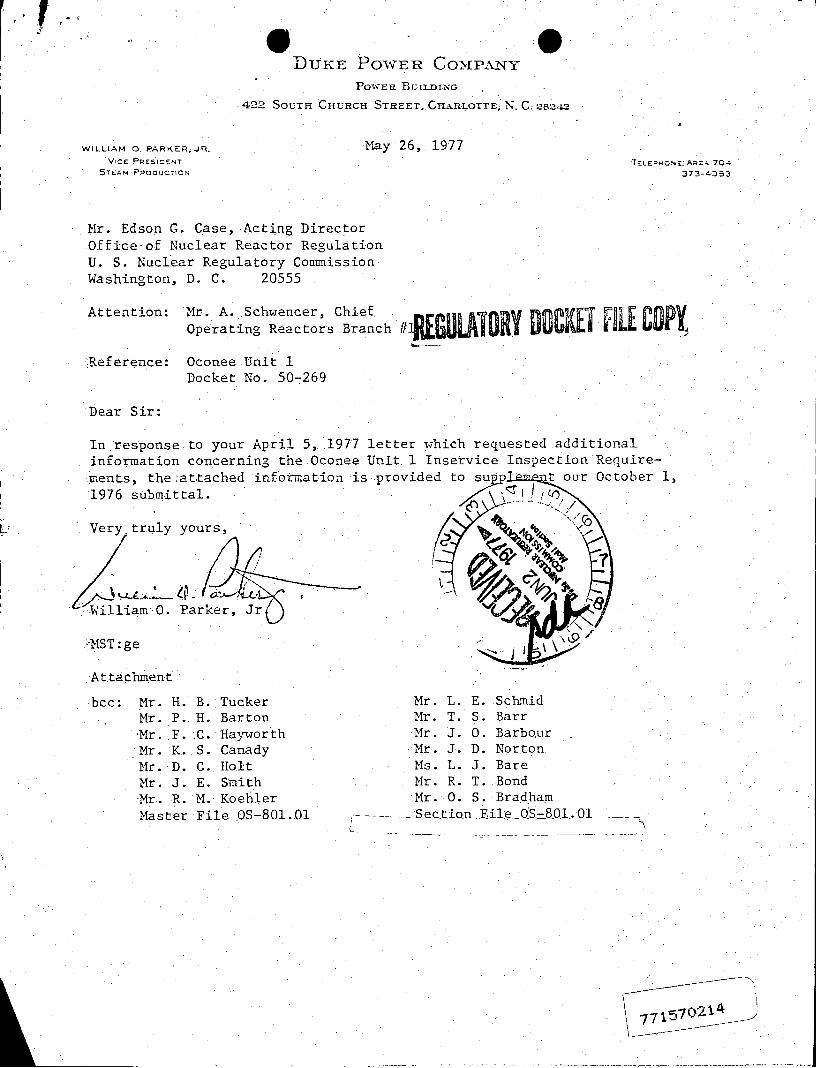
Mr. Edson G. Case, Acting Director Office-of Nuclear Reactor Regulation U. S. Nuclear Regulatory Commission Washington, D. C. 20555
Attention: 'Mr. A. Schwencer, Chief. Operating Reactors Branch IWUAOR UWCKLI PIEL COPY,
Reference: Oconee Unit 1 Docket No. 50-269
Dear Sir:
In response to your April 5, 1977 letter which requested additional information concerning the Oconee Unit 1 Inservice Inspection Require
ments, the attached information.is provided to su p t our October 1,
1976 submittal.
Very, truly yours,
Villiam 0. Parker, Jr
'iMST:ge
Attachment
bcc: 'Mr. H. B. 'Tucker .Mr. L. E. Schmid Mr. P. H. Barton Mr. T. S. Barr Mr. F. C. Hayworth Mr. J. 0. Barbour Mr. K. S. Canady Mr. J. D. Norton
Mr. D. C. Holt Ms. L. J. Bare Mr. J. E. Smith Mr. R. T. Bond 'Mr. R. M. Koehler Mr. 0. S. Bradham
Master File OS-801.O1 - Section EileOS801.0Ol.

RESPON 1TO REQUEST FOR ADDITIONAL INFO ION CONCERNINcMHE OCONEE 1 INSERVICE INSPECTION PROGRAM
ATTACMENT 1 - Conformance with-ASME SectionXIl, Inservice.Examination" Comments
QUESTION
1. Provide additional information using the letter from A. Schwencer, Chief, ORB 1 to W. 0. Parker, Jr., Vice President, Steam Production Duke Power Company, dated November 30, 1976, as guidance, to justify the request for relief from the inservice examination requirements specified in the 1974 -edition of the Section XI Code through the summer 1975 addenda for Code Class 1, .2 and 3 components.
.RESPONSE:
-Attachment 1 to our October. 1, 1976 submittal described those general ;exceptions which are.taken to the ASME Section XI Code due to anticipated impracticalities which was felt would arise during examination of certain Duke Class B and C components. Any portion for which.it is determined that relief from the code requirements is necessary will be submitted to the NRC in accordance with Appendix ?B of Mr.,.A. Schwencer 's letter to Mr. -W. 0. Parker.dated November 30, 1976. At this .time, the only component for which specific relief is requested is the examination of the reactor vessel nozzles. This request for relief is as follows:
1. Component for which relief -is requested:
a. Name and Number: Reactor Pressure Vessel; NRC Docket No. 50-269
b. Function: Reactor Core-SupportReactor Coolant Pressure Boundary
c. ASME Section III Code Class: Equivalent Class I per NRC Regulatory Guide 1.26, Revision2
d.. Valve.Category: Not Applicable
2. ASME Section XI requirement that has been determined to be impractical:
ASME Boiler and Pressure Vessel Code Section XI, 1974 Edition through -Summer 1975 Addenda. Paragraph ItEB-2411;.Subarticle ITB-2500; Table IWB-2500 Category B-D; Table IWB-2600 Item No. B1.4.
3. Basis .for Requesting -Relief:
The net effect of the above Code requirements is that four nozzles, of *a total of eight, must Ibe examined by the-end of 80-months of commercial operation. Dueto core support structures design of Oconee 1, only the two reactor coolant outlet nozzles are accessible without removing the core barrel, which in turn requires complete defueling. This requirement is, therefore, considered to be impractical.
-2
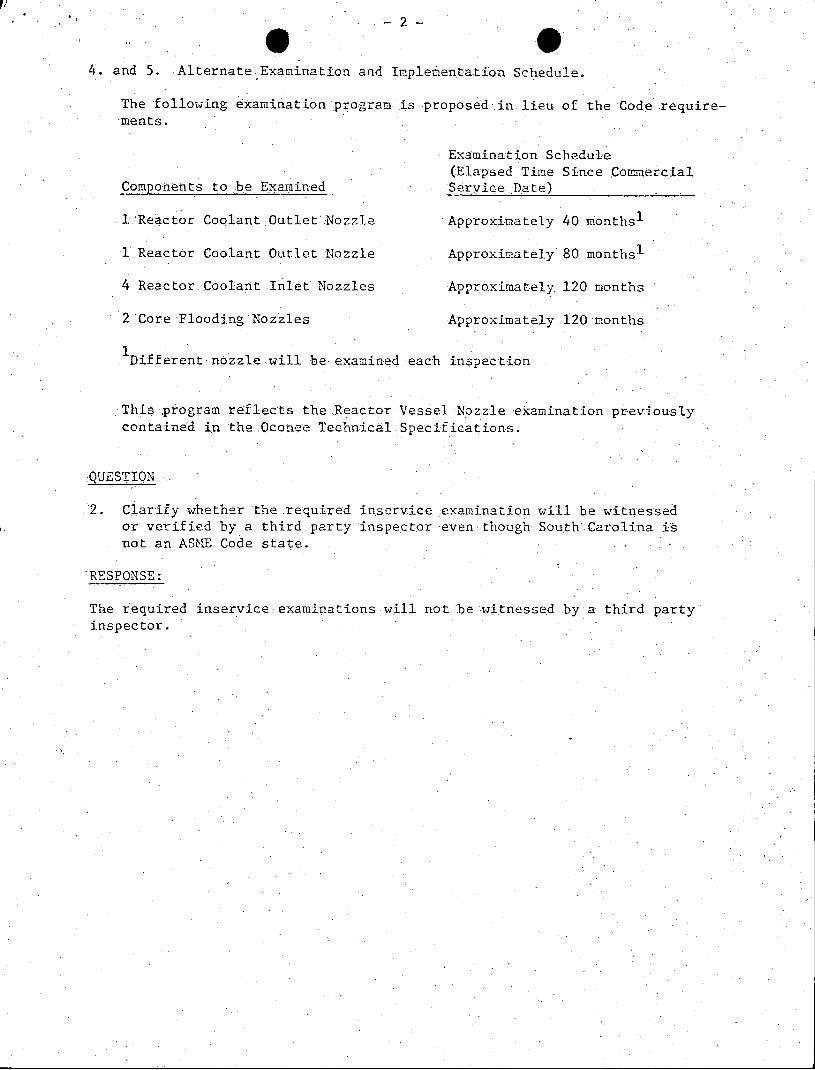
4. and 5. .Alternate Examination and Implementation Schedule.
The following examination program is proposed in lieu of the Code requirements.
Examination Schedule (Elapsed Time Since Commercial
Components to be Examined Service Date)
1 Reactor Coolant Outlet Nozzle Approximately 40 months1
1 Reactor Coolant Outlet Nozzle Approximately 80 months1
4 Reactor Coolant Inlet Nozzles Approximately 120 months
2 Core Flooding Nozzles Approximately 120 months
Different nozzle will be examined each inspection
This program reflects the Reactor Vessel Nozzle examination.previously contained in the ,Oconee Technical Specifications.
QUESTION
2. Clarify whether the .required inservice examination will be witnessed or verified by a third party inspector even though South Carolina is not an ASME Code state.
RESPONSE:
The required inservice examinations will not be witnessed by a third party inspector.
g -3
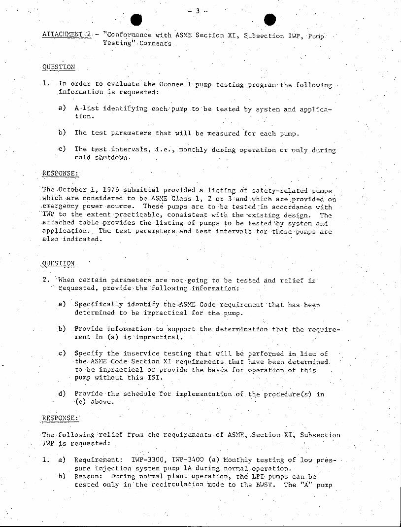
ATTACHMENT 2 - "Conformance with ASME Section XI, Subsection IWP, Pump Testing" Comments
QUESTION
1. In order to evaluate the Oconee 1 pump testing .program the following information is requested:
a) A list identifying each pump to be tested by system and application.
b) The test parameters that will be measured for each pump.
c) The test intervals, i.e., monthly during operation or only during cold shutdown.
RESPONSE:
The October.1, 197.6-submittal provided a listing of safety-related pumps which-are considered to beASME Class.1,.2 or 3.and whichare provided on emergency power source. These pumps are to be tested in accordance with IWP to the extent practicable, consistent .with. the-existing design. The attached table provides the listing of pumps to be tested by system and application. The test parameters and test intervals .for these pumps are also indicated.
QUESTION
2. When certain parameters are not going to be tested and relief is requested, provide the following information:
a) Specifically identify the-ASME Code requirement that has been determined to be impractical for the pump.
b) Provide information to support the determination that the requirement in (a) is impractical.
c) Specify the inservice testing that will be performed .in lieu.of the ASME Code Section XI requirements that have been determined to be impractical or provide the basis for operation of this pump without this ISI.
d) Provide the schedule for implementation-of the procedure(s) in (c) above.
RESPONSE:
Thefollowing relief from the requirements of ASME, Section XI, Subsection IWP.is requested:
1. a) Requirement: IWP-3300, DWP-3400 (a) Monthly testing of low pressure injection system pump lA during normal operation.
b) Reason: During normal plant operation, the LPI pumps can be tested only in the recirculation mode to the BWST. The "A" pump

can only be tested using a piping line-up which contains a 3.inch section of pipe. This restricts~flow to approximately 1150 to 1550 gpm. At this low flow, the installed flow and differential pressure instrumentation does not have sufficient accuracy.and the relatively flat pump head curve combines to prevent repeatability of this test.
c) Proposed Testing: During cold shutdowns (or monthly in the event of frequent shutdowns) the "A" pump can be fully tested in Decay Heat Removal model. During normal plant operation, the pump will be operated in recirculation mode monthly for.15 minutes or until vibration readings. are taken, 'whichevery is longer. Since this pump is used primarily during cold shutdown.operation, degradation is not expected during-periods .of power operation.
d) This schedule for testing has been implemented.
2. :a) Requirement: 1WP-3300 (Table IWP-3100-1) Flow Measurement. For Low Pressure Service Water (LPSW) pump "C".
b) -Reason: 'The LPSW pumps supply two headers, LPA And LPB. The LPB header contains only E.S. components which are equipped with flow transmitters. LPA supplies both ES components 'and a subheader which supplies Non-ES auxiliary equipment>which can be isolated only if both Units 1 and 2 are .at cold shutdown. The output of pumps A & B.may.be measured by isolating the two headers so that the entire output of the pump:being tested.,goes into "B".header while "C" pump supplies "A" header. However, "C" pump cannot be isolated from "A" header while operating.
c) Proposed Testing: All other parameters will be. tested on "C" pump. The. ability of "C" pump to supply the normal requirements of "A" header (which is approximately the same as the ES flow) will verify the general performance of the pump.
d) This testing procedure has been implemented.
3. a) Requirement: IWP-3300 (Table '1P-3100-1) Suction pressure measurement for Spent Fuel Pool Cooling, concentrated Boric Acid, and Low Pressure Boric Acid pump.
b) It is not.considered practical to perform these suction pressure measurements since the necessary instrumentation does not exist.
c) Proposed Testing: Level indications:.exist for .the poolttanks which supply these pumps. These levels, along with.known static head differences from reference levels to pump suctions will pro-vide an approximate indication of the pump suction pressure. Velocity losses should be relatively constant from test to test due to the-repeatability of flow rates and valve-positions for the test.
d) This test procedure has -been implemented.
4. a) Requirement:. IWP-3300 (Table IWP-3100-1) 'Flow for Concentrated Boric.Acid and Low Pressure Boric Acid Pumps.
b) Reason: It is not practical to perform these measurements since flow' measurement devices do not exist in 'these lines.
c) Proposed Testing: None possible 'for this parameter.

* -5
5. a) Requirement:- IWP-3300 (Table IWTP-3100-1 footnote 2), Inlet Pressure Pi, for all pumps which are in operation on a routine basis at the time the testis started.
b) Reason: Several systems are normally in operation with one or more pum ps running. Taking inlet pressure prior to pump -startup would require an additional transfer.to another pump. This (1.) increases the time required for the test, (2) causes additional wear.on thepumps due to extra starts, (3) on some systems this will.require additional tadiation dose during valve lineups prior to swap-over, and (4) presents additional opportunity for human error during transfers.
c) Proposed Testing: Inlet pressure will be taken prior to startup of any standby pumps. Since in most systems standby and operating pumps are alternated periodically, all pumps will 'be checked periodically. Also, on systems where the inlet piping is common, the operational pump will affect the inlet pressure of the standby pump so that operating pressure on one pump would be the same as pre-start pressure on the.standby pump.
d). This testing procedure has been implemented.
6. a) Requirement: IWP-3300 '(Table IWP-3100-1), Lube Oil Level for HPI, CBAT and LP Boric Acid Pumps.
b) Reason: 'No indication exists to. verify lube oil level without partial disassembly of the pump.
c) Proposed Testing: None on'this parameter.
7. a) Requirement: 'WP-3210, (Table 1tP-3200-2) Allowable Ranges of Test Quantities.
b) Reason: In reviewing Section IVP-4100, a general discrepancy was noticed. This is that IWP-4111 and Table IWP-4110-1lspecify that an instrument full scale range.may be four times the reference value-with nominal errors (in most cases) of + 2% of full scale. This permits an error range of + 8% of. the reference value. By Table ITP-3100-2, flow.and pressure readings are allowed to range only +2, -6% (flow) and +2, -7% (pressure). Therefore, a test could fail (exceeding the +3% required to enter the Required Action Range) entirely due to instrument error. -Even recalibration per IWP-3230(b) would not help if the instrument was still within its + 2% full'.scale accuracy.
c) Proposed Testing: Therefore, it is requested that per.IWP-3210 the'ranges'on flow and.pressure be'extended.as shown:
Alert Ranges Required Action Range Test Quantity Acceptable Range Low Values High Values Low Values High Values
AP .92 to 1.08APr .90 to .92APr 1.08 to 1.10APr <.90 Pr >l.10APr Q .92 -to 1.08 Qr .90 to .92 Qr 1.08 to 1.10 Or <.90 Qr >1.10 Qr
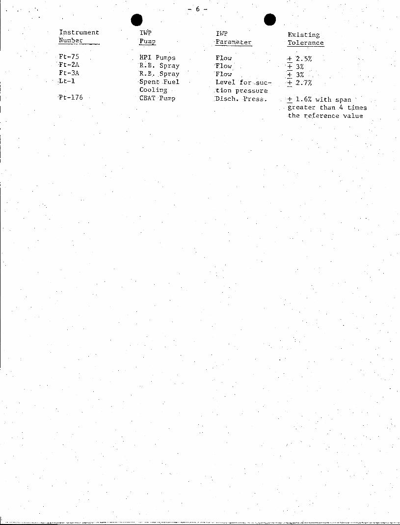
Also, it is requested that.relief from Table IWP-4110-1 be. granted for the installed plant instrumentation listed below which have nominal tolerances greater than + 2% of full scale:
-6
Instrument IVP IP Existing Number PumP Parameter Tolerance
Ft-75 lPI Pumps Flow + 2.5% Ft-2A R.B. Spray Flow + 3% Ft-3A R.B. Spray Flow + 3% Lt-1 Spent Fuel Level for suc- 2.7%
Cooling tion pressure Pt-176 CBAT Pump Disch. Press. 1.6% with span
greater than 4 times the reference value
n to a) 0
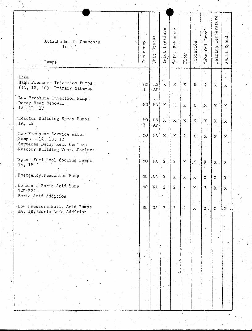
>. l U ) .cc) :0Attachment 2 Comments 1 av 0.
Itemo 1 41 * CU
C) *,) ,- - 0 .f 0 Cj Cu
Pumps
Item High Pressure Injection Pumps No HS X X X X 2 X X (lA, IB, IC) Primary Make-up 1 AP
Low Pressure Injection Pumps 2 Decav Heat Removal MO NA X X X X X X X lA, iB, 1C
'Reactor Building Spray:Pumps MO HS X X X X X X x lA, 1B 1 AP
Low Pressure Service Water MO NA X X 2 x X X X Pumps - 1A, 1B,.1C Services Decay Heat Coolers ,Reactor Building Vent. -Coolers
Spent Fuel Pool Cooling Pumps MO NA 2 2 X X X X X lA, 1B
Emergency.Feedwater Pump MO -NA X X X X x x x
Concent. Boric Acid Pump <MO NA 2 2 2 X 2 X X 1XD-P22 . Boric Acid Addition
Low Pressure-Boric Acid Pumps MO NA 2 2 2 X 2 X X 1A, IB, .-Boric Acid Addition

Notes:
.1. HPI and RB Spray pumps cannot be operated at cold shutdown. Therefore, per I P-3400 (a), they will be tested within 7 days after any cold shutdown which coincides with the due date of..the test.
2. See attached list of requested exemptions for exceptions.
-7
ATTACHMENT 3 - "Conformance with ASME Section XI, Subsection IWV, Valve Testing" Comments
QUESTION
1. Provide code class designations for all valves tested.
2. On your table identify each valve in ASME Section.XI Cat. A that will be leak tested during refueling outages.
3. Provide the test intervals for all valves to be tested. For check valves, identify those that will be exercised only during cold shutdown.
RESPONSE:
The October 1, 1976 submittal provided a listing of those safety-related ASHE Class 1, 2 and'3 valves for which testing is considered to..be required. This .listing was provided to meet the.requirements of .Section IWV-1400 which requires the owner 'to. identify the specific valves to 'be tested. Since no~differentiation in testing requirements exist for various ASHE class valves, the specific code class designation of each valve is unnecessary.
Valves which are-classified as ASME Section XI Category A valves are indicated-on the table of.valves provided in the October 1, .1976 submittal. All valves which require leak -tests will 'be tested annually, most probably during the refueling outage.
Valves.will be tested at the frequency required by.ASME Section XI, Subsection IWV unless.specifically identified on the valve table. Please note a corrected copy ofthe valve list is.attached.
With regard to check valves, the testing frequency will be at least quarterly unless indicated that it cannot be performed'during power operation. In these cases, pursuant to It'V-3520(b) these valves"will be exercised during each plant cold.shutdown but not more often than once every 9 months.
QUESTION
4. Where relief has been requested from certain requirements of the code, specify the inservice,testing that will be performed in lieu of the
ASME Code Section XI requirements that '.are impractical or provide the bases for operation of this valve without this ISI. Also provide the schedule for implementation of this testing.
RESPONSE:
The valve listing attached identifies those valves for which certain
requirements of the code are impractical. -Valves with a cormment code "1"
"are to be tested at time other than power operation as is permitted by Subsections. IV-3410 and I V-3520. Those valves with.a :comment code "2" are impractical to leak test due to the lack-of.appropriate test connections
or isolation valves. Those valves with a conment code "3" are impractical to exercise test. No testing will be performed in lieu of the ASME Code Sedtion.XI requirements that are impractical..
-8
The intent of 10CFR50.55a is to require that throughout the service life of.a nuclear facility the inservice inspection program shall meet:.the requirements of Section XI of editions of the ASME' Boiler and Pressure Vessel Code and Addenda. which become effective to the extent practical. It is our understanding that the code does not require upgrading of. the design of the facility, but rather where practical, to improve the inspection or testing criteria or methods. In the case of Subsection IV for valve testing, certain provisions of the code have been identified which are not practical to meet. These primarily are the results of insufficient test connections or isolation valves to enableleak tests to be performed; inappropriate piping configurations to permit exercise testing of check valves; or unaccessibility of components to verify operation of the valve to be tested. Continued operation without inservice inspection of these components is not considered to be detrimental to the public health and, safety over the "as licensed plant"' for the following reasons: 'Many of the valves are subjected to high system pressures during normal operation and unacceptable leakage.would b-e readily detected, e.g., core flood tank valves CF-3, CF-4, CF-19, CF-33, etc. Some valves which cannot be tested performcontainment isolation functions, however, the downstream piping is adequately designed for accident conditions, e.g.,'HP-20 reactor-coolant
pump seal return; many valves which cannot-be specifically tested are but one of two redundant isolation valves. Additionally, .all -systems are functionally tested during the periodic containment integrated leak rate test to.provide assurance of operability. In consideration of the burden which would ,be imposed to enable testing of these components in accordance with the code, it is not felt that 'the health and safety of the public would. be significantly improved.
Additionally, the following specific relief from the code is requested:
1. a) Requirement: IWV-3410(c) Power operated valves. b) Reason: Power operated valves which operate in very short time
periods (in the.order of one second) are difficult to accurately time. In these instances, thespecified limiting valve of the full stroke time will. generally be considerably greater than the actual full stroke-time. In accuracies in timing contribute to not being able to meet the acceptance criteria of INV-3410(c)(3).
c) :Proposed testing: If any valve with a previously measured stroke time less than or equal to one second is observed to. increase in stroke time to slower than 1.5 seconds, test frequency shall be increased to once each..month until corrective action is taken, at which time the original test frequency shall be resumed. In
any case, any abnormality or erratic action shall be reported."
QUESTION
5. Provide simplified piping diagrams of systems which must functionito
safely shutdown the plant or mitigate the consequences of an accident. Active components on. the above systems which must change position
should be identified. Also, provide..a narrative description of the
valve line-ups required of the systems.identified above each of their
safety functions.
-9
RESPONSE:
P & ID draings have been supplied for review. These drawings indicate active components and should provide adequate information for personnel familiar with operation of a B&W steam supply system to perform this review. If assistance is required in understanding the ophration .of these systems, this could more readily be resolved in verbal discussions than in the requested narrative descriptions.
QUESTION
6. In.addition to the above comments, we have found that in some cases, valves important to plant safety were omitted. Comments on these valves will be made by drawing number.
a) Dwg PI-100-A-1 -Only 2 of the three pressurizer relief valves listed. Valve #/ IRC-66 should be included.
b) Dwg PO--QlA-l - Valves listed on this drawing are containment isolation valves. Check valve iJP-194 should be included if possible to the test program.
c) Dwg PQ-102A-1 - Valves BS-3 and BS-4, Power.:operated valves on the suction lines to the'reactor building spray.pumps are omitted. They should be included or justification provided for not including them.
d) Dwg PQ-103A-1,2,3 - Check valves BS-14 and BS-19 are proposed to be tested every 5 years. A source of instrument air exists (according to the drawing) for spray nozzle testing.. The licensee should consider using the instrument air to test the check valves on a more.frequent schedule.
.e) Dwg PO-122A-1 - Only one of sixteen main steam safety reliefs is listed. Provide justification for not including the others.
f) Dwg.P0-127-B - We cannot locate N2 isolation valves lN-91 thru IN-94. These may be mis-numbered on.submittal. Theyshould be N-105, .106, and 107. Confirm and correct technical specification as required.
RESPONSE:
a) Valve lRC-66. is the power operated relief valve as distinguished from the other two code relief valves. This valve performs no specific safety function and does.not have specific leakage requirements other than.the Technical Specification primary coolant leakage requirements. It is not considered that this valve should require testing.
b) Check valve HP-194 has been included in the test program as indicated in the attached revised table.
c) Power.operated valves BS-2-and BS-4 have been included in the test program as indicated in the attached revised table.
- 10
d) The current OconeeTechnical Specifications require the testing of valves .BS-14 and .BS-19,at five year intervals. Due to the.difficulty in obtaining accessibility in verifying instrument air flow through the spray nozzles, it is considered that this test is not practical at more frequent intervals. .Since these valves are not subjected to liquids and are not in a corrosive atmosphere, it is considered that this test interval is-satisfactory.
e) All-sixteen main steam safety valves will be tested as indicated on the revised valve table.
f) Valves 1N-91 thru 1N-94 were included by error.. The correct valves should be 1N-106 and IN-107. Valve 1N-105 does not require .
testing as it performs no isolation function.

ATTACHMENT 4 - "Proposed Technical Specification Revision, Inservice Inspection" Comments
QUESTION
1. Because of difference-in the date of start of facility commercial operation for Oconee Units 1, 2 and 3, we recommend that separate Technical Specification be established for.each unit.
RESPONSE:
Oconee Unit 1 was required to conform to the provisions of 10CFR50.55a beginning November 15, 1977. Oconee Units 2 and 3 will be required to meet these criteria on January 9, 1978.and April 16, 1978, respectively. The October 1, 1976 submittal provided proposed Technical-Specifications amendments which were designed to separate the surveillance requirements of Oconee 1 and Oconee 2,3. In the future, after. Oconee 2 and 3 meet the criteria of lOCFR50.55a, the.Technical Specifications language should be general enough to permit common usage for all three Oconee units.
QUESTION
2. The language in the Technical Specifications 4.04 and 4 . 2 .1,is not acceptable. The sample technical specification language recommended in the :letterfrom R. A. Purple, Chief, Operating Reactors Branch #1, NRC to Duke Power Company, dated April 26, 1976 should be used, i.e., 4.2.1 - Inservice inspection of -ASME Code Class 1, 2 and 3 components shall be performed in accordance with Section XI of the ASME.Boiler and Pressure Vessel Code and applicable Addenda.as required by 1OCFR50, Section .50.55a(g), except where specific written relief has been :granted by the NRC pursuant to 10CFR50, Section.50.55a(g)(6)(i).
4.0..4 -Inservice testing of ASME Code Class 1, 2.and 3 pumps and valves.shall be performed in accordance with-Section Xl of the ASME Boiler andPressure Vessel Code-and applicable.Addenda as required by IOCFR50,..Section 50.55a(g), except where specific written relief has been granted by -the NRC pursuant to IOCFR50, Section 50.55a(g)(6)(i).
RESPONSE:
The .provisions of 10CFR50.55a(g)(i) require that Oconee 1 meet the inservice inspection requirements -of paragraphs (g)(4) and (g)(5) to the extent.practical. Paragraph (g)(4) requires that "components classified as ASME Code Class 1, 2.and 3 shall meet the requirements except design and access provisions and preservice examination-requirements ....... that become effective subsequent to editions......in paragraph (b) of this section to the extent practical within the limitations of design,. geometry and materials of
construction of the components".
Paragraph (g)(5)(i) requires the licensee to revise the inservice inspection program, as-necessary, to meet the provisions of paragraph (g)(4).
Paragraph (g) (5) (ii) requires that License Amendments -be submitted at least. six months before the start of a period if the revised inservice inspection program conflicts with the Technical Specifications of the facility.
- 12
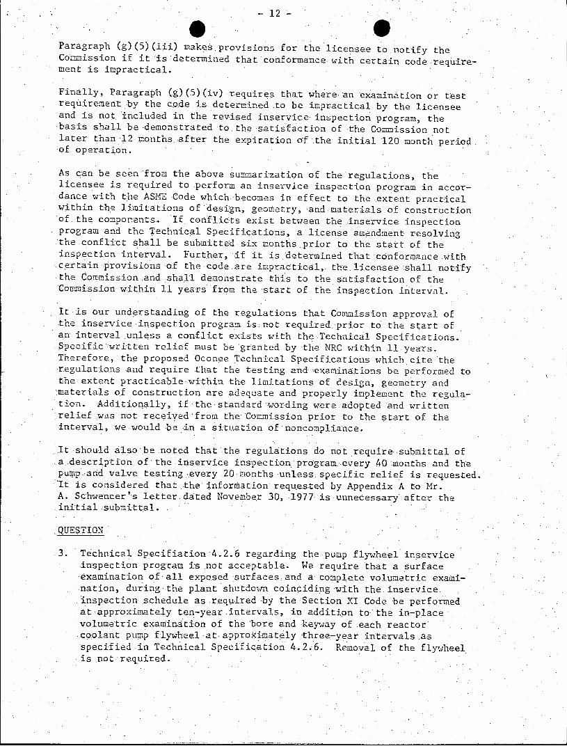
Paragraph (g)(5)(iii) makes.provisions for the licensee to notify the Commission if it ;is determined that'conformance with certain code requirement is impractical.
Finally, Paragraph (g)(5)(iv) requires that where an examination or test requirement by the code is.determined ..to be impractical by the licensee
..and is not included in the revised inservice inspection program, the basis shall be -demonstrated to the satisfaction of the Commission not later than 12 months.after the expiration of the initial 120 month period of. operation.
As can be .seen from the above summarization of the regulations, the licensee is required to perform an inservice inspection program in accordance with the ASME Code which becomes in effect to the extent practical within the limitations of design, geometry, and materials.of construction of.the components. If. conflicts exist between the inservice inspection program and the Technical Specifications, a license amendment resolving the.conflict shall be submitted six months.prior to the start of the inspection interval. Further, if it is determined that conformance with certain provisions of the code are impractical,. the.licensee shall notify the Commission and shall demonstrate this to the satisfaction of the Commission within 11 years from the start of the inspection interval.
It is our understanding of the regulations that Commission approval of the inservice inspection program is not required.prior to the start of an interval unless a conflict exists with the Technical Specifications. Specific written relief must be granted by the NRC within 11 years. Therefore, the proposed Oconee Technical Specifications which cite the regulations and require that the testing and examinations.be performed to the extent practicable-within the limitations of design, geometry and 'materials of construction are adequate and properly implement the regulation. Additionally, if the standard wording were adopted and written relief was not received from the Commission prior to the start of the interval, we would be in a situation of noncompliance.
It should also be noted that the regulations do not require submittal of .a..description of the inservice insoection program every 40 months and the pump aind valve testing every.20-months unless specific relief is requested It is considered that .the information requested by Appendix A to Mr. A. Schwencer's letter-dated November 30, 1977 is unnecessary after the initial submittal.
QUESTION
3. Technical Specifiation-4.2.6 regarding the pump flywheel inservice inspection program is not acceptable. We require that a surface -examination of all exposed surfaces and a complete volumetric examination, during-the plant shutdown coinciding with the inservice. inspection schedule as required -by the Section XI Code be performed at approximately ten-year.intervals, in addition to the in-place volumetric examination of the bore and keyway of .each reactor coolant pump flywheel at approximately -three-year intervals as specified in Technical Specification 4.2.6. Removal of the flywheel is not required.
- 13
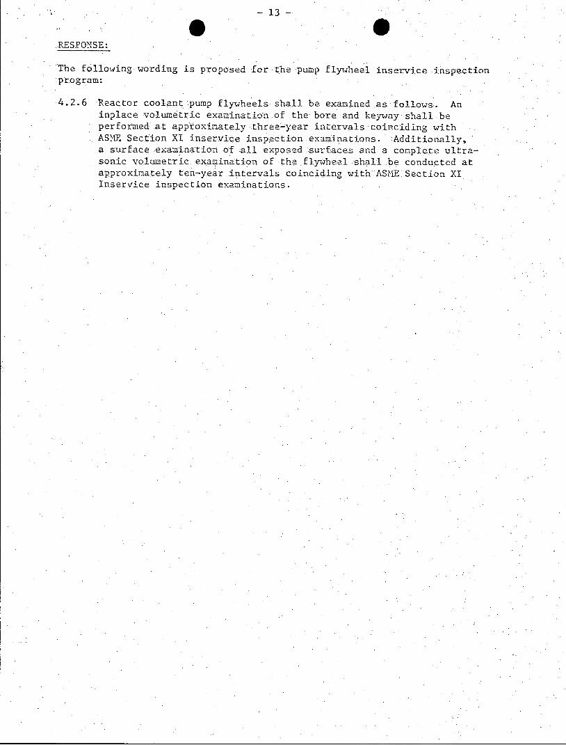
RESPONSE:
The following wording is proposed for the pump flywheel inservice inspection program:
4.2.6 Reactor coolant pump flywheels shall be examined as follows. An inplace volumetric examination of the bore and keyway shall be performed at approximately three-year intervals coinciding with ASME Section XI inservice inspection examinations. Additionally, a surface examination of all exposed surfaces and a complete ultrasonic volumetric examination of the flywheel shall be conducted at approximately ten-year intervals. coinciding with ASE. Section XI Inservice inspection examinations.

OCONEE UNIT 1 CONFORMANCE WITH ASME SECTION XI, SUBSECTION IWV
O *0 (D (n- Hfl 0D-t 771 O DRAWING NO. A -CDD CH r f0-gC 0 H P P 0 Cf'
VaIveNo. Valve Name M rU 7 C! (D < (D < C) 7 l 1< aL Comments
PO-100OA-1 1RC-67 Pressurizer Relief R C
1RC-68 Pressurizer Relief R X C
PO-101A-1 111P-24 A HPI Pump Suct. From BWST P X B 1HP-25 C HPI Pump Suet. From BWST P X B
1Hlp-101 A HPI Suct. Check Vlv. C X C 1 lIP-102 C HPI Suct. Check Viv. C X C 1 1HP-105 A HPI Disch. Check Vlv. C X C 1H{P-109 B HIPI Disch. Check Vlv. C :K C 111P-113 C H1PI Disch. Check Vlv. C X C lICA-85 BAIT to LDST C X C ICA-73 CBAST to LDST C X C 1HP-16 Makeup to LDST P X B 1LP-57 LPI to p C Train C X C 1 1LP-55 LPI to HPI B Train C X C 1
PO-101B-l 1H4P-3 A LD Cooler Outlet P X X A/B 1HP-4 B LD Cooler Outlet P X X A/B 1HP-5 LD Cooler Isolation P X X A/B 1HP-20 RC Pump Seal Return P X X A/B 1,2 1HP-21 RC Pump Seal Return P X X A/B 1 1HP-26 A Loop Injection P X B lIP-27 B Loop Injection P X B
IHP-188 B Loop Check Valve C X C 1 1HP-153 B Loop Check Valve C X C 1 1HP-152 B Loop Check Valve C X C 1 1HP-194 A Loop Check Valve C X C PO-102A-1 ICF-3 A CFT Sample/Drain. P X A 2 ICF-4 B CFT Saple/Drain P X A 2
-1-
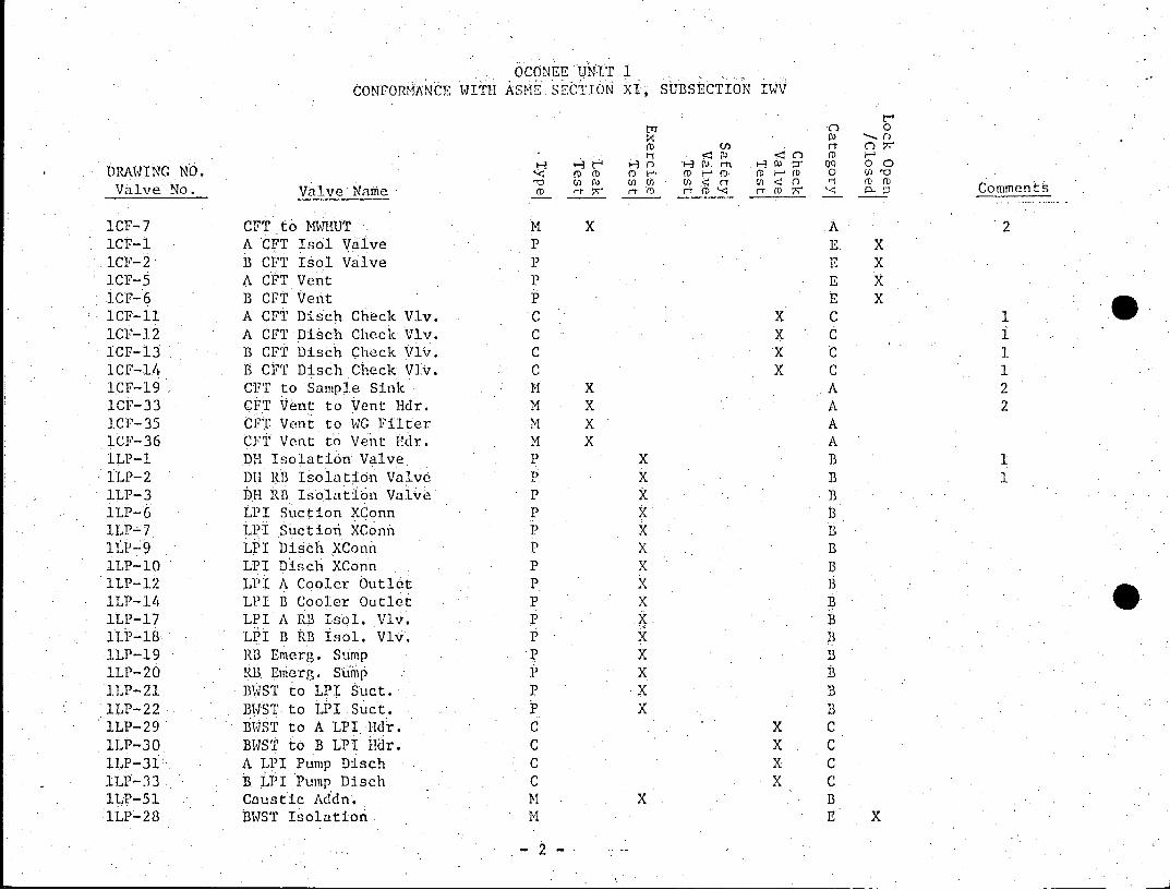
OCONEE UNLIT 1 CONFORMANCE WITH ASME SECTION XI, SUBSECTION IWV
0 r)
(0 0t 0~ H H~Hn H~ H0 on oo DRAWING NO. ((D (D F-D ( -o 0 h
Valve No. Valve Name D._ 0 f _ _ (_ '-< ::3 Comments
1CF-7 CFT to MWHUT M X A 2 ICF-1 A CFT Isol Valve P E X 1CF-2. B G'T Isol Valve P E X ICF-5 A CFT Vent P E X ICF-6 B CFT Vent P E X ICF-11 A CFT Disch Check Vlv. C X C 1CF-12 A CFT Disch Check Vlv. C X C ICF-13 B CPT Disch Check Vlv. C X C 1CF-14 B CFT Disch Check VIv. C X C 1CF-19 CFT to Sample Sink M X A 2 ICF-33 CFT Vent to Vent Edr. M X A 2 ICF-35 CFT Vent to WG Filter M X A ICF-36 CFT Vent to Vent Hdr. M X A lLP-1 DH Isolation Valve P X B ILP-2 DH RB Isolation Valve P X B ILP-3 DH RB Isolation Valve P X B 1LP-6 LPI Suction XConn P X B 1LP-7 LPI Suction XConn P X B 1LP-9 LPI Disch XConn P X B 1LP-10 LPI Disch XConn P X B 1LP-12 LPI A Cooler Outlet P X B lLP-14 LPI B Cooler Outlet P X B 1LP-17 LPI A RB Isol. Vlv. P X B lLP-18 LPI B RB Isol. Vlv. P X B 1LP-19 RB Emerg. Sump p X B lLP-20 RB Emerg. Sump P X B 1LP-21 B.ST to LPI Suct. P X B 1LP-22 BWST to LPI Suct. P X B lLP-29 BUST to A LPI Hidr. C X C 1LP-30 BWST to B LPI Hdr. C X C 1LP-31 A LPI Pump Disch C X C 1LP-33 B LPI Pump Disch C X C ILP-51 Caustic Addn. M X B 1LP-28 BUST Isolation M E X
-2-
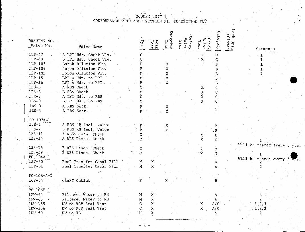
OCONEE UNIT 1 CONFORMANCE WITH ASME SEC'ION XI, SunSECTIO IV
ni 0
DRAWI G NO. tr F t74 H- 09 0o U) P3 ( (nCI w<r U)< M (D Valve No. Valve Nane < m D arr (D i- (C
Comments
1LP-47 A LPI 1-dr. Check Vlv. C X C 1 lLP-48 B LPI Hdr. Check Vlv. C X C 1 1LP-103 Boroh Dilution Vlv. P X B 1 lLP-104 Boron Diltuion Vlv. P X B 1 lLP-105 Boron Dilution Vlv. P X B 1 1LP-15 LPI A Hdr. to HPI P X B lLP-16 LPI A 11dr. to HPI P X B lBS-5 A RBS Check C X C 1BS-6 B RBS Check C X C 1BS-7 A LPI Ikr. to RBS C X C 1BS-9 B LPI Hdr. to RBS C X C lBS-3 A RBS Suct. P X B IBS-4 B RBS Suct. P X
PO-103A-1 1BS-1 A. RBS RB Isol. Valve P XB 1BS-2 B ISS RB Iso.. Valve P X B lBS-11 A RBS Disch. Check C.X C IBS-14 A RBS Disch. Check C X C1
Will be tested every 5 yrs. lBS-16 B RBS Disch. Check d X C lBS-19 B RBS Disch. Check C X C 1
roWA^1ill be tested every 5110. 1SP-60 Fuel Transfer Canal Fill M X A 2 lSF-61 Fuel Transfer Canal Fill M X A 2
PO-10 6-A-1 1CS-64 CBAST Outlet P X B
PO-106E-1 1FW-64 Filtered Water to RB M X A 2 1FW-65 Filtered Water to RB M X A 2 :1DW-155 DW to RCP Seal Vent C X X A/C IDW-156 DW to: RCP.Se:l Vent C X X A/C 1,2,3 1DW-59 DW to RB M X A 2
3-
OCONEE UNIT 1 CONFORMANCE WITH ASME SECTION XI, SUBSECTION IWV
C 0 fuI 0
DRAWING NO. c roo w o HW(D 0 o
ValveNo. Valve Name (D (_ D r ( Comments
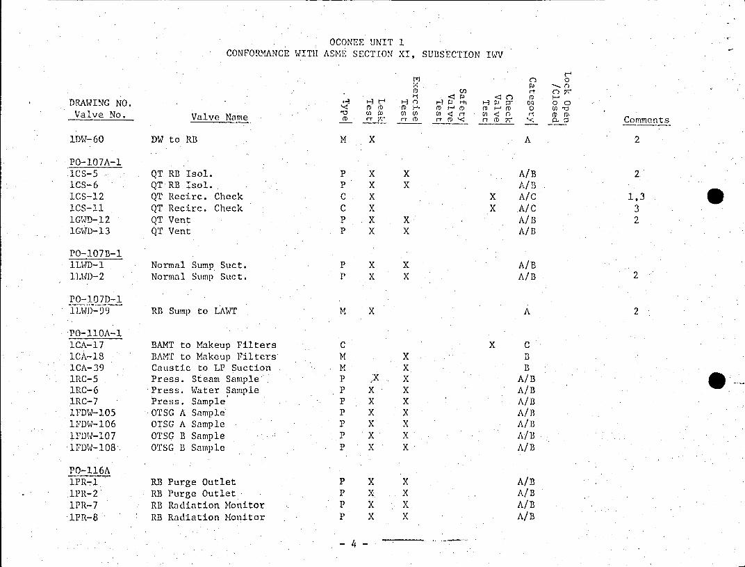
1DW-60 DW to RB M X A 2
PO-107A-1 ICS-5 QT RB Isol. P X X A/B 2 ICS-6 QT RB Isol. P X X A/B 1CS-12 QT Recirc. Check C X X A/C 1,3 ICS-11 QT Recirc. Check C X X A/C 3 1GWD-12 QT Vent P X X A/B 2 1GCD-13 QT Vent P X X A/B
PO-107B-1 1LWD-1 Normal Sump Suct. P X X A/B 1LWD-2 Normal Sump Suct. P X X A/B 2
PO-107D-1 ILWD-99 RB Sump to LAWT M X A 2
PO-11OA-1 ICA-17 BAMT to Makeup Filters C X C 1CA-18 BAMT to Makeup Filters M X B ICA-39 Caustic to LP Suction M X B 1RC-5 Press. Steam Sample P X X A/B 1RC-6 Press. Water Sample P X X A/B 1RC-7 Press. Sample P X X A/B 1FDW-105 OTSG A Sample P X X A/B 1FDW-106 OTSG A Sample P X X A/B 1FDW-107 OTSG B Sample P X X A/B IFDW-108 OTSG B Sample P X X A/B
PO-116A 1PR-1 RB Purge Outlet P X X A/B 1PR-2 RB Purge Outlet P X X A/B
1PR-7 RB Radiation Monitor P X X A/B 1PR-8 RB Radiation Monitor P X X A/B
-4-
OCONEE UNIT 1 CONFORMANCE WITH ASME SECTION XI, SUBSECTION IV
0r 0
DRAWING NO. He . n Hw wD : 0 0 0 M ~ ~ ~ ~ ' (D (DH DM D 0 U
Valve No. ValvNe Name M - A r D ( (2 Cort<enents
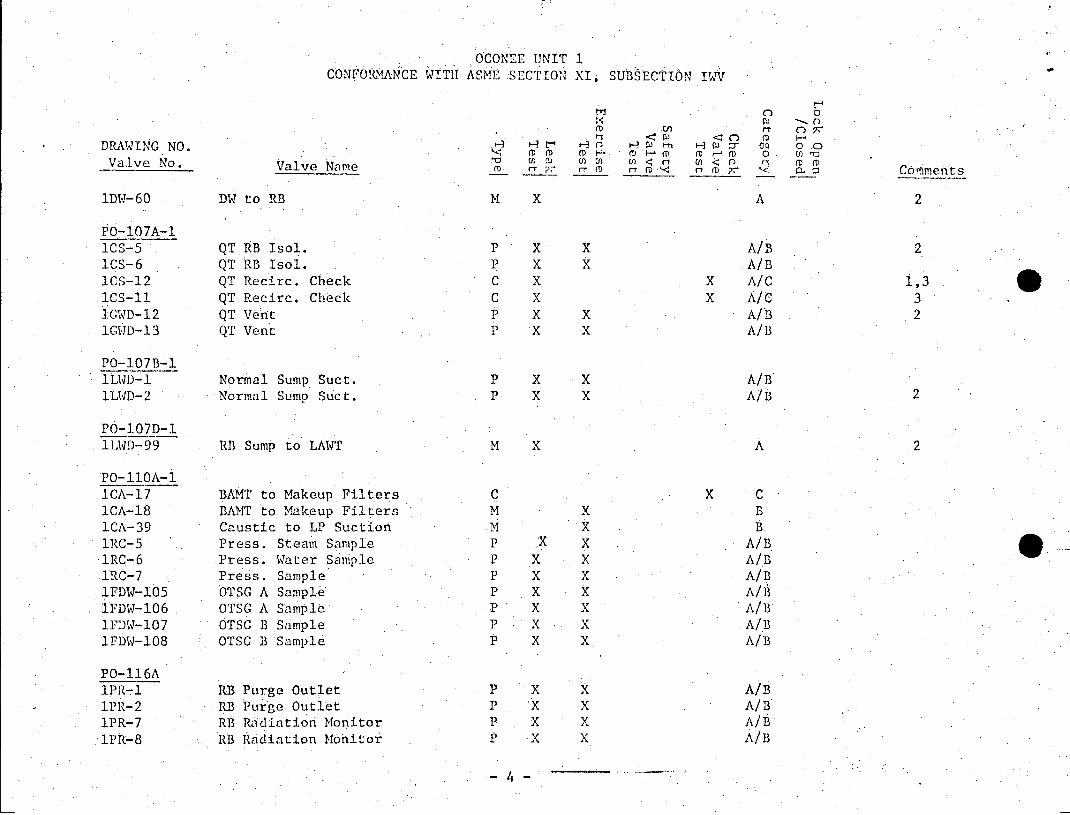
1DW-60 DW to RB M X A 2
PO-107A-1 1CS-5 QT RB Isol. P X X A/B 2 1CS-6 QT RB Isol. P X X A/B
1CS-12 QT Recirc. Check C X X A/C 1,3 .
ICS-1l QT Recirc. Check C X x A/c 3 IGWD-12 QT Vent P X X A/B 2 10D-13 QT Vent P X X A/1
PO-107B-1 1LVD-1 Normal Sump Suct. P X X A/B
1LWD-2 Norinal Sump Suct. P X X A/B 2
PO-107D-1 ILWD-99 RB Sump to LAWT M X A 2
PO-11OA-1 ICA-17 BAMT to Makeup Filters C X C 1CA-18 BAMT to Makeup Filters M X B 1CA-39 Caustic to LP Suction M- X B 1RC-5 Press. Steam Sample P X X A/B lRC-6 Press. Water Saniple P X X A/B 1RC-7 Press. Sample P X X A/B 1FDW-105 OTSG A Sample P X X A/B IFDW-106 OTSG A Sample P X X A/B 1FDW-107 OTSG B Sample P X X A/B 1FDW-108 OTSG B Sample P X X. A/B
PO-116A 1PR-1 RB Purge Outlet P X X A/B 1PR-2 RB Purge Outlet P X X A/B 1PR-7 RB Radiation Monitor P X X A/B
1PR-8 RB Radiation Moito . P X X A/B
-4-
OCONEE UNIT 1 CONFORMANCE WITH ASME SECTION XI, SUBSECTION IWV
O . 0 0
(D n r c 71
DRAWING NO. < t-1 H m-C 03 cD 0 o
Valve No. Va < 1 CD D Valve Name mD y r (D D rt (D p; __ Comments
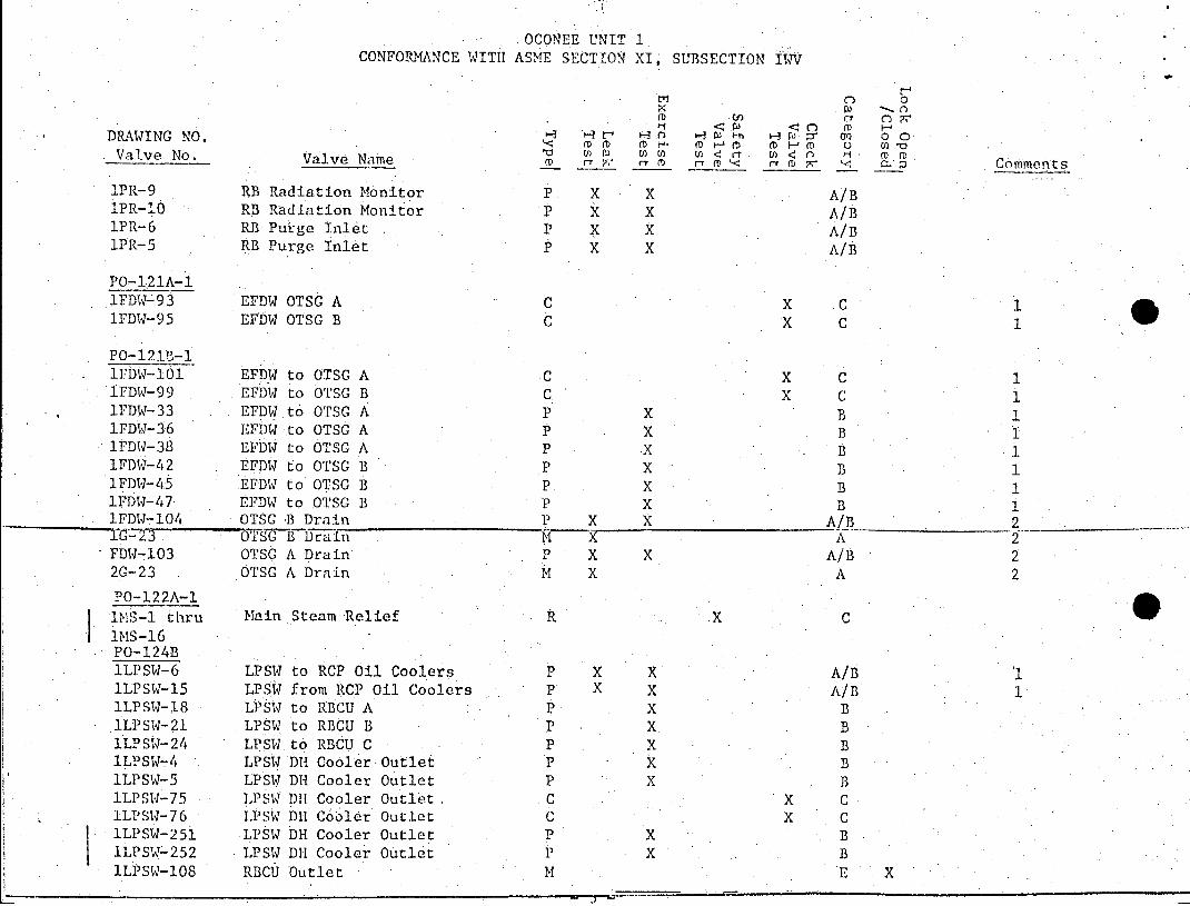
1PR-9 RB Radiation Monitor P X X A/B 1PR-10 RB Radiation Monitor 1 X X A/B 1PR-6 RB Purge Inlet P X X A/B 1PR-5 RB Purge Inlet P X X A/B
PO-121A-1 lFDW-93 EFDW OTSG A C X C 1FDW-95 EFDW OTSG B C X C 1
PO-121B-1 1FDW-101 EFDW to OTSG A C X C 1 IFDW-99 EFDW to OTSG B C X C 1FDW-33 EFDW to OTSG A P X B 1 IFDW-36 EFDW to OTSC A P X B 1FDW-38 EFDW to OTSG A P X B1 1FDW-42 EFDW to OTSG B P X B 1 1FDW-45 EFDW to OTSG B P X B 1 1FDW-47 EFDW to OTSG B P X B 1 1FDW-104 OTSG -B Drain P X X A/B 2 10-2 TSG B Drain M X A 2 FDW-103 OTSG A Drain P X X A/B 2 2G-23 OTSG A Drain M X A 2
PO-122A-1
IS-1 thru Main Steam Relief R X C 1MS-16 PO-124B lLPSW-6 LPSW to RCP Oil Coolers P X X A/B 1 lLPSW-15 LPSW from RCP Oil Coolers P X X A/B 1 1LPSW-18 LPSW to RBCU A 1 X B 1LPSW-21 LPSW to RBCU B P X B lLPSW-24 LPSW to RBCU C P X B lLPSW-4 LPSW DH Cooler Outlet P X B lLPSW-5 LPSW DH Cooler Outlet P X B lLPSW-75 LPSIA4 DH Cooler Outlet C X C 1LPSW-76 LPSW DR Cobler Outlet C X C lLPSW-251 LPSW DH Cooler Outlet P X B 1LPSW-252 LPSW DH Cooler Outlet P X B 1LPSW-108 RBCU Outlet M E X
OCONEE, UNIT 1 CONFORMANCE WITH ASME SECTION XI, SUBSECTION IV
0
on o (0 r- C 7',
DRAWING NO. o M ( Hm H D D M 0 0 M0 Cn0 W~l C rt En n f-1 (D rD
Valve No. ValveName aDn 217 a cComments
PO-127B
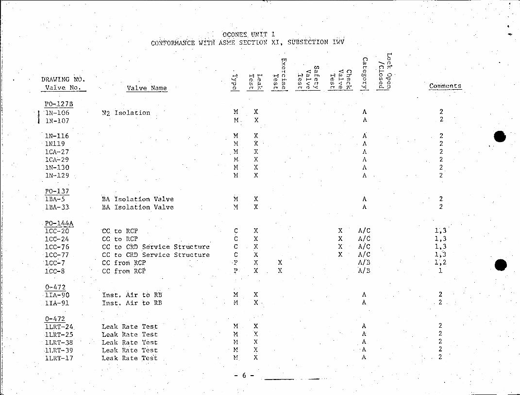
1N-106 N2 Isolation M X A 2
I1N-107 M X A 2
1N-116 M X A 2 IN119 M X A 2 ICA-27 M X A 2
ICA-29 M X A 2
IN-130 M X A 2 1N-129 M X A 2
PO-137 1BA-5 BA Isolation Valve M X A 2
IBA-33 BA Isolation Valve M X A 2
PO-144A ICC-20 CC, to RCP C X X A/C 1,3
1CC-24 CC. to RCP C X X A/C 1,3
ICC-76 CC to CRD Service Structure C X X A/C 1,3
ICC-77 CC to CRtD Service Structure C X X A/C 1,3
1CC-7 CC from RCP ? X X A/B 1,2
1CC-8 CC from RCP P X X A/B 1
0-472 lIA-90 Inst. Air to RB M X A 2 1IA-91 Inst. Air to RB M X A 2
0-472 1LRT-24 Leak Rate Test M X A 2
lLRT-25 Leak Rate Test M X A 2
lLRT-38 Leak Rate Test M X A 2
1LRT-39 Leak Rate Test M X A 2
lLRT-17 Leak Rate Test M X A 2
-6 -
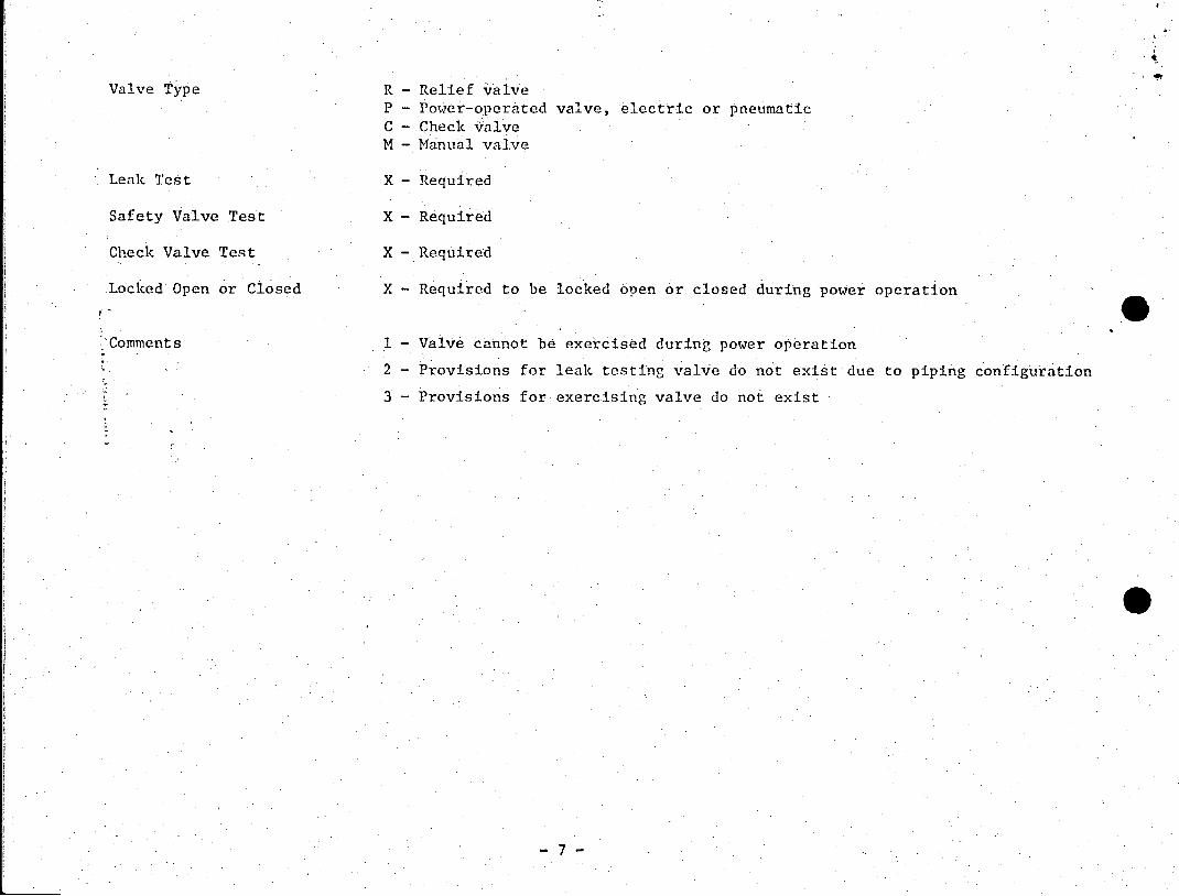
Valve Type R - Relief valve P - Power-operated valve, electric or pneumatic C - Check valve M - Manual valve
Leak Test X - Required
Safety Valve Test X - Required
Check Valve Test X - Required
Locked Open or Closed X - Required to be locked open or closed during power operation
Comments 1 - Valve cannot be exercised during power operation
2 - Provisions for leak testing valve do not exist due to piping configuration
3 - Provisions for exercising valve do not exist
-7-

RECEIVED 0OCtUME PROCES!% UIT