Embed Size (px)
Citation preview

OCT &%w ENGINEERING DATA TRANSMITTAL
N/A 14. Required Response Date:
P.0. 1 Of I 1. EDT
15.
8. Originator Remarks:
ATTACHED IS AN ACCEPTANCE TEST PLAN (ATP) FOR THE NEW PUMPING AND INSTRUMENTATION (PIC) SKIDS BEING FABRICATED BY SITE FABRICATION SERVICES.
1 1. Receiver Remarks: NONE
. . 11A. Design Baseline Document? @ Yes 0 No
(8) DocumenVDrawing No. No.
N/A 10. Sy&MMgfisdilty:
241-U 12. MajorAs.sm. Dwg. No.:
N/A 13. PermWPermit Application No.:
1 RPP-5055
~
4pprovai Designator (F)
16. ~~ ~ ~~~ ~ ~~
Reason for Transmittal (G) Disposition (H) 8 (I)
KEY I
I E S Q DORN/A 1. Ap roval 4. Review 1. Approved 4. Reviewed nolwmment (SbeLvkC-CM-3-5, I 2.
Regaoe 5. Post-Review 2. Approved w/wmment 5. Reviewed w/wmment Sec. 12.7) 3. Information 6. Dist. (Receipt Acknow. Required) 3. Disapproved w/wmment 6. Receipt acknowledged
Authorized Re resentative Date for Receiving grganization I 6 DisaDDroved w/mmments I
ID-7400-172-2 (10/97) BD.7400172-1

5 RPP-5055, Rev. 0
ACCEPTANCE TEST PROCEDURE FOR NEW PUMPING AND INSTRUMENTATION CONTROL SKID " L"
M. R. KOCH LOCKHEED MARTIN HANFORD CORPORATION Rlchland, WA 99352 US. Department of Energy Contract DE-AC06-96RL13200
EDTIECN: 624841 uc: OrgCode: 7 4 ~ 0 0 Charge Code: 103361 BaR Code: EW3120071 Total Pages: 5 7
& Keywords: PICS, SALT WELL, SKID, INTERIM STABILIZATION, TESTING
Abstract: This Acceptance Test Procedure (ATP) provides for the inspection and testing of the new Pumping and Instrumentation Control (PIC) skid designed as "L". The ATP will be performed after the construction of the PIC skid in the shop.
TRADEMARK DISCLAIMER. Reference herein to any speufic wmmeraal product, p~0o.u. or SONIC. by tnda name. tndurmrk, mmufadunr. or OthamiM, doer not nemsrariiy wnsldute or impiy Ib e n d o m n t . m o m n d a t b n . or hvorlng by the U n M Stater Government or any agency thereof or I$ contractor8 or rubcontradon.
Printed h the U n M Stater of America To obtain copies of this dowmenl mntad Document Control Se~icss, P.O. Box Ow, Malbbp H6-08. Richland WA 99352. Phons (509) 372-2420, Fax (509) 37M989.
Date
Approved For Public Release

RPP-5055 REVISION 0
TABLE OF CONTENTS
1.0 PURPOSE ............................................................................................................................... 1 2.0 INFORMATION ..................................................................................................................... 1
2.1 SCOPE ................................................................................................................................ 1 2.2 TERMS AND DEFINITIONS ............................................................................................ 2 2.3 RESPONSIBILITIES ......................................................................................................... 2 2.4 SAFETY ............................................................................................................................. 3 2.5 QUALITY ASSURANCE .................................................................................................. 3 2.6 GENERAL INFORMATION ............................................................................................. 3 2.7 LIMITS AND PRECAUTIONS ......................................................................................... 4
3.0 RECORDS .............................................................................................................................. 4 3.1 RECORD COPY ................................................................................................................. 4 3.2 TEST RESULTS ................................................................................................................. 4
4.0 PREREQUISITES .................................................................................................................. 5 4.1 DRAWING VERIFICATION ............................................................................................ 5 4.2 PRESSURE VESSEL INSPECTION .... ............................................................................ 6 4.3 NATIONAL ELECTRICAL CODE (NEC) INSPECTION ............................................... 6 4.4 SUPPLIES .......................................................................................................................... 7 4.5 PRESTART CONDITIONS ............................................................................................... 8
5.0 PROCEDURE ....................................................................................................................... 10 5.1 CONTINUITY CHECKS ................................................................................................. 10 5.2 MEGGERING OF POWER WIRES ................................................................................ 12 5.3 ELECTRICAL POWER CHECKS .................................................................................. 14 5.5 SKID ELECTRICAL POWER UP ................................................................................... 17 5.6 CALIBRATIONS ............................................................................................................. 18 5.7 PLCDTAM PROGRAMMING ....................................................................................... 18
5.9 SKID WATER DRIP SYSTEM ....................................................................................... 26 5.10 ANALOG INPUT SIGNALS TO THE PLC AND DTAM ............................................. 29 5.1 1 DISCRETE SIGNAL INPUTS TO PLC AND DTAM .................................................... 39 5.12 HEATERS AND AIR CONDITIONER ........................................................................... 43 5.13 LEAK DETECTION INTERLOCK CHECK .................................................................. 45 5.14 SKID SHUTDOWN AFTER ATP .................................................................................... 48 5.15 REDLINE INCORPORATION ........................................................................................ 50
5.8 SKID ELECTRICAL AND PROCESS AIR POWER-UP .............................................. 19
i
RPP-5055 REVISION 0
ACCEPTANCE TEST PROCEDURE FOR NEW PUMPING AND INSTRUMENTATION CONTROL SKID “L”
1.0 PURPOSE
This Acceptance Test Procedure (ATP) verifies proper construction per the design drawings and tests for proper functioning of the Pumping and Instrumentation Control (PIC) skid “L”. The Scope section lists the systems and functions to be checked. This ATP will be performed at the Site Fabrication Service’s (SFS) shop upon completion of construction of the PIC skid.
2.0 INFORMATION
2.1 SCOPE
This Acceptance Test Procedure verifies and/or tests the following systems:
2.1.1 Drawing verification (Prerequisites)
2.1.2Code inspections (Prerequisites)
2.1.3Instrument calibrations
2.1.4Continuity, megger and voltage checks
2.1.5PLC Programming
2.1.6Air system
2.1.7Water system
2.1.8PLC inputs and outputs
2.1.9 Heaters and air conditioner
2.1.10 Leak Detector Interlocks
1

RPP-5055 REVISION 0
2.2 TERMS AND DEFINITIONS
2.2.1 DOV - Diaphragm Operated Valve 2.2.2 GPM - Gallons Per Minute 2.2.3 IA - Instrument Air 2.2.4 LDE - Leak Detector Element 2.2.5 PRV - Pressure Relief Valve 2.2.6 SGT - Specific Gravity Transmitter 2.2.7 WFT - Weight Factor Transmitter 2.2.8 LT - Level Transmitter 2.2.9 WFIE - Weight Factor Instrument Enclosure 2.2.10 PLC - Programmable Logic Controller 2.2.1 1 DTAh4 - Data Table Access Module 2.2.12 PSPT - Pump Suction Pressure Transducer 2.2.13 PDPT - Pump Discharge Pressure Transducer 2.2.14 JFPT - Jumper Flush Pressure Transducer 2.2.15 RFPT - Recirculation Flush Pressure Transducer 2.2.16 PIC - Person In Charge
2.3 RESPONSIBILITIES
2.3.1 LMHC Quality Assurance is responsible for:
2.3.1.1
2.3.1.2
Engineering personnel are responsible for:
2.3.2.1 2.3.2.2 2.3.2.3 2.3.2.4 2.3.2.5 2.3.2.6 2.3.2.7
Witnessing and signing steps as identified in Acceptance Test Procedure. Verifying that the procedure sections were performed correctly.
2.3.2
Identifying the equipment needed for this procedure. Recording equipment status and data per this procedure. Conducting pre-job system walk down. Recording data, exceptions and other notes as required. Providing technical support during testing. Providing programming support during testing. Forcing data in Programmable Logic Controller program during testing.
2

RPP-5055 REVISION 0
2.4 SAFETY
Warning: when accessing PLC input/output terminals or the serial communication port. Observe appropriate electrical precautions as directed by HNF-PRO-088, Electrical Work Safety.
Warning: 120vac. Comply with HNF-PRO-088, Electrical Work Safety.
120 VAC energized circuits and leads will be encountered during test
Cabinets on the PIC skid contain circuits energized with 480vac and
2.5 QUALITY ASSURANCE
Ensure that the testing is performed per this procedure. The LMHC Quality Assurance Inspector shall sign and date each procedure section verifying the data obtained, and verifying that the procedure section has been performed correctly.
2.6 GENERAL INFORMATION
2.6.1
2.6.2
2.6.3
2.6.4
2.6.5
2.6.6
2.6.7
2.6.8
All data entries recorded in this procedure shall be made in black or blue ink. Editorial changes required to this ATP may be made by redlining the affected section by the engineer as long as the change does not impact personnel safety or the technical aspects of this procedure. These changes shall be recorded on the ATP log sheet. Unexpected results during testing shall be logged in the Acceptance Test Procedure “Exception Log” and documented on an Acceptance Test Procedure “Exception Record.” Technical changes to this test shall be logged as “Exceptions” and documented on the “Exception Record.” Do not perform any part of this procedure on faulty equipment. If faulty equipment is discovered, STOP the execution of that section of this procedure and resolve the problem OR continue with another section until the problem is repaired. If the performance of this procedure is suspended for any reason, ensure the equipment is left in a safe condition per direction of the test engineer and/or PIC.
This procedure DOES NOT contain separate datdverification sheets. Verification of procedural steps and validity of data is recorded in this procedure next to each step as required.
If performance of this procedure is suspended for any reason, ensure if necessary, any Lock and Tag system requirements are met before leaving the test site.
3

RPP-5055 REVISION 0
2.6.9 A Job Huard Analysis form shall be used in conjunction with the pre-job safety meeting form when any unusual hazards are identified. The pre-job meeting form shall be used to document all attendees.
performance such as each day’s testing activities.
safe equipment configuration during testing or suspension of testing. Configuration shall be noted so the equipment may be restored at resumption of testing.
engineer or PIC if specific instructions are not given in the test steps.
facilitate completion of this ATP.
2.6.10 An ATP log shall be used to record comments concerning ATP
2.6.1 1 The engineer or PIC may deviate from test steps if necessary to ensure
2.6.12 Alarms may be acknowledged during testing at the direction of the test
2.6.13 Sections 4.2,4.3 and 5.13 can be performed out of sequence in order to
2.7 LIMITS AND PRECAUTIONS
NONE
3.0 RECORDS
3.1 RECORDCOPY
The record copy of this procedure when completed shall be kept with the fabrication work package.
3.2 TEST RESULTS
A test report, RPP-5056 shall be issued with the final test results upon completion of this ATP.
4

RPP-5055 REVISION 0
4.0 PREREQUISITES
4.1 DRAWING VERIFICATION
A check of the constructed skid is to be compared to either the redlined drawings or the final unreleased skid drawings. Engineering and Quality Assurance shall verify the accuracy of the essential and support drawings. Engineering shall determine a resolution for all discrepancies by either correcting the drawings or changing the equipment.
The following drawings shall be walked down for verification of proper construction of the skid:
4.1.1 Wire terminations and wiring labeling on drawings H-14-103538, sheets 7 through 12 and H-14-103541, sheet 5.
4.1.2 Panel board arrangement on drawing H-14-103537. 4.1.3 Flow diagrams on drawings H-14-103538, sheet 5 and H-14-103543.
Drawing verification completed. (Final drawing release is not required to continue with this ATP.)
Cognizant Engineer Signature Date
Quality Assurance Inspector Signature Date
5

RPP-5055 REVISION 0
4.2 PRESSURE VESSEL INSPECTION
A pressure vessel inspection by a third party inspector is required for the air compressor, the air receiver tank and relief valves located in the air compressor cabinet and the water tank and relief valves in the water cabinet. The inspection is to verify that the equipment meets National Codes for pressure vessels. An outside-certified inspector will perform this inspection. (This inspection shall be completed prior to checking the air compressor and water systems.)
Pressure vessel inspection report received. (The ATP can continue before the report is received, but must be received prior to performing section 5.8.)
Report #
Quality Assurance Inspector Signature Date
4.3 NATIONAL ELECTRICAL CODE (NEC) INSPECTION
4.3.1 An NEC inspection shall be performed to verify compliance to NFPA 70, latest version.
4.3.2 Areas in particular to be inspected are 48Ovac and 12Ovac wiring and grounding.
4.3.3 An NEC inspection sticker is to be placed inside the panel board door upon the NEC inspector’s acceptance of the electrical portion of the skid.
The NEC inspection performed and an NEC inspection sticker placed on the panel board door. (This needs to be completed prior to the section 5.0 functional checks.)
Report #
Quality Assurance Inspector Signature Date
6

RF'P-5055 REVISION 0
4.4 SUPPLIES
The following supplies are required for this ATP: Note: Test sections may commence prior to assembly of all the test equipment. Engineer and/or PIC are to ensure test equipment available prior to the start of each section.
4.4.1 Volt/ohm meter (VOM): Portable, 0-6OOvac.
Calibration No. Exp. Date QA -
Calibration No. Exp. Date QA -
4.4.2 Transmation current (milliamp) simulator or equivalent
Calibration No. Exp. Date QA -
Calibration No. Exp. Date QA -
4.4.3 Manometer (capable of a minimum of 5 inches water gauge to a maximum of 20 inches water gauge for this ATP) must have a read out of variable test pressure.
Calibration No. Exp. Date QA -
Calibration No. Exp. Date QA ~
4.4.4 Megaohm meter, at least 5OOvac range.
Calibration No. Exp. Date QA -
4.4.5 - 48Ovac, 3 phase, 30-ampere power source for PIC skid. 4.4.6 - Selector switches (2 each) with at least one NO and one NC contact. 4.4.7 - Proximity switches (for simulating LS-1 and LS-2), 2 each. 4.4.8 - Leak detector probes (2 each), (Not required to be green tagged.) or
2 ON/OFF switches can be used to simulate leak detectors.
7

RPP-5055 REVISION 0
4.5 PRESTART CONDITIONS
4.5.1 -Fill the water tank at least one-third to half full of water.
4.5.2 - Ensure the PIC skid is grounded in preparation for ATP testing.
4.5.3 Ensure the following PIC skid valves in the WFIE cabinet are OPEN prior to starting this ATP.
-SALW-V-6035L (EQUALIZING) -SALW-V-6036L (EQUALIZING)
4.5.4 Ensure the following PIC skid valves are CLOSED prior to starting this - ATP.
Air Compressor cabinet:
-SALW-V-6025L -SALW-V-6026L -SALW-V-6034L -SALW-V-6043L -SALW-V-6044L -SALW-V-6046L -SALW-V-6047L -SALW-V-6048L -SALW-V-6049L
WFIE Cabinet:
Water cabinet:
SALW-V-6027L SALW-V-6028L SALW-V-6029L S ALW-V-6030L SALW-V-6031L SALW-V-6032L SALW-V-6037L
-SALW-V-6015L -SALW-V-6016L -SALW-V-6017L -SALW-V-6018L -SALW-V-6019L -SALW-V-6020L -SALW-V-6021L -SALW-V-6035L LOW -SALW-V-6035L HIGH -SALW-V-6036L LOW -SALW-V-6036L HIGH
8

RPP-5055 REVISION 0
4.5.5 Ensure the following PIC skid circuit disconnects, breakers and fuses are OPEN or OFF prior to starting this ATP.
-SALW-DS-6002L - SALW-DS-6003L -SALW-DS- 6004L -SALW-DS-6005L
The following breakers are in distribution panel SALW-DP-6001L:
-Breaker “MAIN” -Breaker 2 -Breaker 1 -Breaker 4 -Breaker 3 B r e a k e r 6 -Breaker 5 -Breaker 8 -Breaker 7 -Breaker 10 -Breaker 9 -Breaker 12 -Breaker 11 -Breaker 14 -Breaker 13
The following fuses are inside the Instrument Enclosure:
-Fuses FA/FB -Fuses FCFD -Fuses (Leak detectormeat trace)
4.5.6 Check for lose electrical connections at the following locations:
-Terminal boards in Instrument Enclosure -Motor starters and disconnect switches -Terminal board in junction box inside the WFIE cabinet -Terminal board in junction box for FGM outside WFIE cabinet -Terminal board in heat trace splice box outside WFIE cabinet -Distribution panel board -480vac power plug
4.5.7 - Ensure desiccant and filters are installed in the air compressor dryer and the before and after filters.
4.5.8 - All personnel initialing and/or signing this procedure shall enter their signature and initials on the Procedure Performer Signature Sheet on the last page of this document.
4.5.9 -A pre-job safety meeting has been held before starting section 5.0 of this ATP.
9

RPP-5055 REVISION 0
5.0 PROCEDURE
5.1 CONTINUITY CHECKS
Continuity checks shall be performed with a calibrated VOM. Perform the checks as identified below. Readings are to be less than 1 ohm. Record ohms reading on the line(s) provided. Out of tolerance readings must be corrected and rechecked prior to going to the next section. NOTE: NEC inspection must be completed prior to proceeding.
5.1.1 48Ovac main power plug to line side of main disconnect switch (SALW- DS-6002L). Check all three phases and ground.
-(RED) - (YELLOW) - (BLUE) ~ ( G W
5.1.2 Load side of main disconnect switch (SALW-DS-6002L) to line side of transformer disconnect switch (SALW-DS-6003L). Check all three phases and ground.
5.1.3 Load side of main disconnect switch (SALW-DS-6002L) to line side ofjet pump motor starter (SALW-DS-6005L). Check all three phases and ground.
-(RED) - (YELLOW) - (BLUE) - (GNW
5.1.4 Load side of main disconnect switch (SALW-DS-6002L) to line side of air compressor motor starter (SALW-DS-6004L). Check all three phases and ground.
5.1.5 Load side of transformer disconnect switch (SALW-DS-6003L) through primary of transformer (SALW-XFMR-6001L). Check between the two- phase wires going to the transformer.
-(continuity through transformer primary)
10

RPP-5055 REVISION 0
5.1.6 Line side of main breaker in panel board (SALW-DP-6001L) through secondary of transformer (SALW-XFMR-6001L). Check between the two phases and between each phase and neutral going to the transformer secondary.
-(Phase-A to phase-C, continuity through transformer secondary)
-(Phase-A to neutral, continuity through transformer secondary)
-(Phase-C to neutral, continuity through transformer secondary)
5.1.7 Load side ofbreakers in distribution panel (SALW-DP-6001L) to terminal point identified:
-Circuit 3 to TBlO in Instrument Enclosure -Circuit 5 to TB13 in Instrument Enclosure -Circuit 12 to Air Conditionerrneater receptacle in Instrument Enclosure -Circuit 6 to safe side terminal board in Intrinsic Safe Panel -Circuit 1 to terminal board in FGM power junction box -Circuit 11 to terminal board in FGM power junction box -Circuit 13 to terminal board in FGM power junction box -Circuit 14 to terminal board in FGM power junction box -Circuit 2 to terminal board in FGM heat trace splice box -Circuit 10 to terminal board in FGM heat trace splice box -Circuit 4 to receptacle in air compressor cabinet -Circuit 7 to receptacles in WFIE cabinet -Circuit 8 to receptacle in Water cabinet -Circuit 9 to outside receptacle below panel board
Section 5.1 completed and all recorded readings within tolerance.
Quality Assurance Inspector Signature Date
11

RPP-5055 REVISION 0
5.2 MEGGEFUNG OF POWER WIRES
The power wires shall be checked for resistance to ground and phase to phase. A 500- volt megger shall be used for this check. Minimum acceptable readings expected are greater than 1000 megaohm or infinity. Test the circuits listed below. Record readings on the lines provided. Out of tolerance readings must be corrected and rechecked before going to the next section.
5.2.1 Each of the three phases at the pins of the power plug to ground and phase to phase. (Ensure main disconnect SALW-DS-6002L is OPEN.)
A-GND-, ' B-GND-, . C-GND-; A-B -7 ' A-C-, ' B-C-
5.2.2 Each of the three phases at the load side of the main disconnect switch (SALW-DS-6002L) to ground and phase to phase. (Ensure switches SALW-DS-6003L, SALW-DS-6004L and SALW-DS-6005L are OPEN.)
A-GND-, ' B-GND-, ' C-GND-; A-B-, . A-C-, B-C-
5.2.3 Each of the two phases on the load side of the transformer disconnect switch (SALW-DS-6003L) to ground.
5.2.4 Each of the three phases on the load side of the air compressor motor to ground.
A-GND-, ' B-GND-, ' C-GND-
5.2.5
5.2.6 Each of the two phases and neutral to ground at the distribution panel.
A-GND -7 ' B-GND-, ' NEUTW-GND-
5.2.7 - Reconnect the ground to the neutral at the distribution panel.
5.2.8
Disconnect the neutral at the distribution panel from ground.
Disconnect the circuit 6 wire at the safe side terminal block in the intrinsic safe panel.
12

RPP-5055 REVISION 0
5.2.9 Megger each of the 14 circuits from the wire disconnected at the load side of the breaker to ground in the distribution panel.
NOTE: Disconnect each wire from the load side of the breaker prior to performing the megger check. Reconnect after meggering.
CKT.#I to GND-, ’ CKT.#2 to GND-, . CKT.#3 to GND-, . CKT.#4 to GND-, . CKT.#5 to GND-, . CKT.#6 to GND-, . CKT.#7 to GND-; CKT.#8 to GND-, ‘ CKT.#9 to GND-, . CKT.#10 to GND-, . CKT.#ll to GND-, ’ CKT.#12 to GND-, . CKT.#13 to GND-, . CKT.#14 to GND-;
5.2.10 - Ensure the load-side wire at each breaker is connected.
5.2.11 - Reconnect the circuit-6-wire to the safe side terminal board at the Intrinsic safe panel.
Section 5.2 completed and all recorded readings are within tolerance.
Quality Assurance Inspector Signature Date
13

RPP-5055 REVISION 0
5.3 ELECTRICAL POWER CHECKS
The voltage checks are to verify proper voltages throughout the skid at specific termination points. Voltages checked are 48Ovac, 3 phase; 120vac, single phase; and 24vdc. Out of tolerance readings must be corrected when found before going to the next step in this section.
5.3.1 - Ensure that all electrical connections are completed. Wires lifted during the megger checks are to be reconnected.
5.3.2 -Ensure all switches and breakers are open and the six fuses in the instrument cabinet are open.
5.3.3 - Ensure that all the fuses are in the two safety switches (SALW-DS- 6002L) (SALW-DS-6003L) and motor starters (SALW-DS-6004L) (SALW-DS-6OOSL) including the control transformers are installed.
5.3.4 - Connect the main power plug on the skid to a three phase, 48Ovac power source. Source to be protected by no greater than 30 amperes over current protection.
5.3.5 -Turn ON the power source to the skid.
5.3.6 - Verify 480vac +10vac/-20vac on the line side of the main disconnect switch (SALW-DS-6002L). Record the voltage.
vac A-B vac A-C vac B-C
5.3.7 -Close the main disconnect switch (SALW-DS-6002L).
5.3.8 - Verify 480vac +10vac/-20vac on the line side of the transformer disconnect switch (SALW-DS-6003L). Record the voltage.
vac A-C
5.3.9 - Verify 480vac +lOvac/-20vac on the line side of the air compressor motor starter (SALW-DS-6003L). Record the voltage.
vac A-B vac A-C vac B-C
14

RPP-5055 REVISION 0
5.3.10 - Verify 48Ovac +lOvac/-20vac on the line side of the pump motor vac A-B starter (SALW-DS-6005L). Record the voltage.
vac A-C vac B-C
5.3.11 - Remove the dead front on the panel board (SALW-DP-6001L) for access to the main breaker for a voltage measurement.
5.3.12 ~ Close the transformer disconnect switch (SALW-DS-6003L).
5.3.13 - Check for 24Ovac +lo/-20 at the line side of the main breaker. Record voltage. vac
5.3.14 ~ Open the transformer disconnect switch (SALW-DS-6003L).
5.3.15 -Replace the dead front on the panel board (SALW-DP-6001L).
5.3.16 - Close the transformer disconnect switch (SALW-DS-6003L).
5.3.17 - Close the 100 ampere main breaker in the panel board (SALW-DP- 6001L).
15
RPP-5055 REVISION 0
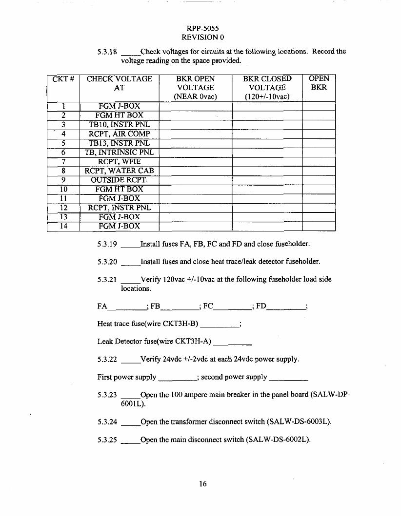
5.3.18 - Check voltages for circuits at the following locations. Record the voltage reading on the space provided.
5.3.19 - Install fuses FA, FB, FC and FD and close fuseholder.
5.3.20 - Install fuses and close heat trace/leak detector fuseholder.
5.3.21 - Verify 120vac +/-lOvac at the following fuseholder load side locations.
FA ; FB ; FC ; FD
Heat trace fuse(wire CKT3H-B)
Leak Detector fuse(wire CKT3H-A)
5.3.22 ~ Verify 24vdc +I-2vdc at each 24vdc power supply.
First power supply
5.3.23 ~ Open the 100 ampere main breaker in the panel board (SALW-DP-
; second power supply
6001L).
5.3.24 - Open the transformer disconnect switch (SALW-DS-6003L).
5.3.25 - Open the main disconnect switch (SALW-DS-6002L).
16

RPP-5055 REVISION 0
Voltage checks completed satisfactorily.
SWITCHOR Close Open Close Open Close Open Close BREAKER
Quality Assurance Inspector Signature Date
5.5 SKID ELECTRICAL POWER UP
open
During the following sections for instrument calibration and PLCDTAM programming, electrical power will be required to the skid. The following sequence can be used to power up and power down the skid. Record breakers closed or opened in table below. Only circuits required to be powered need to be Closed.
SALW-DS-6002L SALW-DS-6003L CKT. #1 CKT. #2
1 CKT. #3 I I I I I I I I
17

RPP-5055 REVISION 0
5.6 CALIBRATIONS
Instrumentation equipment on the skid requires calibration prior to the functional testing. Lockheed Martin procedures will be used for this calibration. The table below identifies the equipment requiring calibration and the procedure for performing the calibration.
INSTRUMENT SALW-PS-6004L SALW-WFT-6002L SALW-LT-6003L SALW-SGT-6001 L SALW-CONV-600 1L SALW-FQIT-6001L SALW-PI-6006L SALW-PI-6001L SALW-PI-6005L SALW-PI-6002L SALW-PI-6003L SALW-PI-6004L SALW-PI-6007L SALW-PI-6008L
LOCATION PROCEDURE INSTRU. AIR CAB. 6-PCD-508 WFIE CABINET 6-PCD-361 WATER CABINET 6-PCD-361 WFIE CABINET 6-PCD-361 WFIE CABINET 6-CVT-520 INSTRUMENT CAB. AIR COMPRS. CABINET 6-TF-509
Data sheet & Vendor Man.
WFIE CABINET 6-TF-509 WFIE CABINET 6-TF-509 WFIE CABINET 6-TF-509 WFIE CABINET 6-TF-509 WFIE CABINET 6-TF-509 AIR COMPRS. CABINET 6-TF-509 WATER CABINET 6-TF-509
Calibrations completed. Work package no.
Engineer Signature Date
5.7 PLC/DTAM PROGRAMMING
This section is where the programs for the PLC and DTAM will be entered. Power will be required at the instrument cabinet to power up the PLC and DTAM. Power will also be required to the GFCI receptacle for power to the laptop computer. Lockheed Martin Interim Stabilization engineering will perform the programming of the PLC and DTAM. The final software programs shall be documented as required by HNF-3828, section 3.4. This documentation is not part of this ATP, but will be tracked by the Acceptance for Beneficial Use (ABU) document.
PLCDTAM programmed.
Engineer Signature Date
18

RPP-5055 REVISION 0
5.8 SKID ELECTRICAL AND PROCESS AIR POWER-UP
NOTE: The Third Party Pressure Vessel inspection report must be received prior to proceeding with this section. Refer to section 4.2.
5.8.1- ENSURE the skid and remote equipment are connected before proceeding with the functional testing.
5.8.2- ENERGIZE the Pumping and Instrumentation Control Skid by CLOSING the following DISCONNECT SWITCHES in the order found below:
DISCONNECT SWITCH
19

RPP-5055 REVISION 0
5.8.3- ENERGIZE the Pumping and Instrumentation Control Skid by CLOSING the following Circuit Breakers located in SALW-DP-6001L “SALW SKID DIST PNL” in the order found below:
DISCONNECT SWITCH ENERGIZED (I/)
20

RPP-5055 REVISION 0
5.8.4- ACKNOWLEDGE any initial skid alarms.
5.8.5- OPEN valve SALW-V-6034L (located in the Air COMP Cabinet).
5.8.6- START air compressor SALW-CMP-6001L "SALW SKID IA COMP" by POSITIONING switch on the SALW-DS-6004L to the ON position.
5.8.7- V E R I N that Air Compressor starts and builds up pressure AND shuts off at 86 to 94 psig, as indicated by pressure gauge SALW-PI-6006L (AIR DRYER INLET PRESS). Record shut off pressure: psig
Engineer Signature Date
5.8.8 CHECK the tubing in the instrument air cabinet using a soap and water test to visually identify any air leaks. Repair as necessary. Deenergize the compressor motor and bleed off air as necessary to make repairs.
5.8.9 - BLEED off air by slowly opening valve SALW-V-6043L until the compressor restarts, then close the valve and note the restart pressure.
5.8.10 - VERIFY the air compressor restarts upon low pressure of 58 to 62 psig. Record pressure: p s i g
5.8.11 - VALVE in air to the PIC Skid Water Tank by SLOWLY PERFORMING the following (Refer to H-14-103543 Sheet 1):
5.8.12 CHECK for air leaks as each remaining step in this section is performed. Make repairs as necessary. Deenergize compressor motor and bleed off air pressure if necessary to make the repairs.
5.8.13 - SLOWLY OPEN valve SALW-V-6025L located in the air compressor cabinet.
5.8.14 __ SLOWLY OPEN valve SALW-V-6027L (located near the water tank).
5.8.15 - SLOWLY OPEN valve SALW-V-6028L (located near the water tank).
21

RPP-5055 REVISION 0
5.8.16 - ADJUST Pressure Regulator Valve SALW-PCV-6006L to 30 psi (t 3 psig) as indicated by pressure gauge SALW-PI-6008L (WTR TK PRESS).
5.8.17 - VALVE IN air to WFIE Cabinet by PERFORMING the following (Refer to H-14-103543 Sheet 1):
5.8.18 - SLOWLY OPEN valve SALW-V-6026L located in the Air Compressor Cabinet.
5.8.19 - SLOWLY OPEN valve SALW-V-6001L, located in the bottom of WFIE Cabinet. (NOTE: SALW-PRV-6002L may open if pressure through SALW-PCV-6001L is too high.)
5.8.20 - ADJUST pressure control valve SALW-PCV-6001L in WFIE Cabinet to 20 psi (. 2.5 psi) as indicated by the pressure gauge located on the face of the valve.
5.8.21 - SLOWLY OPEN valve SALW-V-6004L, located in the middle of WFIE Cabinet.
5.8.22 __ SLOWLY OPEN valve SALW-V-6003L, located in the middle of WFIE Cabinet.
CAUTION: The next three steps cause air to flow from ports on outside of WFIE
cabinet.
5.8.23 - SLOWLY OPEN valve SALW-V-6005L, located in the bottom left of WFIE Cabinet.
5.8.24 - SLOWLY OPEN valve SALW-V-6006L, located in the bottom left of WFIE Cabinet.
5.8.25 __ SLOWLY OPEN valve SALW-V-6007L, located in the bottom left of WFIE Cabinet.
5.8.26 - SLOWLY OPEN valve SALW-V-6020L, located in the middle left of WFIE Cabinet.
5.8.27 - SLOWLY OPEN valve SALW-V-602lL, located in the middle left of WFIE Cabinet.
5.8.28 - SLOWLY OPEN valve SALW-V-6019L, located in the middle left of WFIE Cabinet.
22

RPP-5055 REVISION 0
5.8.29 - ADJUST the air flow through the diptubes by PERFORMING the following:
5.8.30 - ADJUST flow to dip tubes to 1.5 CFH (i 0.5 CFH) as indicated by SALW-FIV-6002L.
~
Flow Engineer Signature Date
5.8.31 - ADJUST flow to dip tubes to 1.5 CFH (i 0.5 CFH) as indicated by SALW-FIV-6003L.
~
Flow E r Date
5.8.32 - ADJUST flow to dip tubes to 1.5 CFH (i 0.5 CFH) as indicated by SALW-FIV-6004L.
Flow Engineer Signature Date
5.8.33 - VALVE IN SALW-WFT-6002L AND SALW-SGT-6001L by PERFORMING the following:
5.8.34 __ ENSURE the LOW side AND HIGH side isolation valves, located on SALW-V-6036L in cabinet WFIE Cabinet are OPEN.
5.8.35 __ ENSURE SALW-WFT-6OO2L EQUALIZING valve on valve manifold SALW-V-6036L in cabinet WFIE Cabinet is CLOSED.
5.8.36 - ENSURE the LOW side AND the HIGH side isolation valves, located on SALW-V-6035L in cabinet WFIE Cabinet are OPEN.
5.8.37 - ENSURE SALW-SGT-6001L equalizing valve on valve manifold SALW-V-6035L in cabinet WFIE Cabinet is CLOSED.
5.8.38 - CONFIRM that a signal is present between WFIE Cabinet instruments and the Programmable Logic Controller by PERFORMING the following:
, 23

RPP-5055 REVISION 0
5.8.39 - VERIFY Weight Factor is approximately 0.0" (*OS'') Water Gauge as indicated by Data Table Access Module. If DTAM displays 'I<<<<"
indicating less than zero, verify continuity between the transmitter and the Programmable Logic Controller and proceed with the test.
Engineer Signature Date
5.8.41 - VERIFY Specific Gravity is approximately 0.0" (+0.5") Water Gauge as indicated by Data Table Access Module. If DTAM displays "<<<<" indicating less than zero, verify continuity between the transmitter and the Programmable Logic Controller and proceed with the test.
Engineer Signature Date
5.8.42 - OPEN valve SALW-V-6035L Equalizing.
5.8.43 - CLOSE valves SALW-V-6035L HI and LO.
5.8.44 ___ OPEN valve SALW-V-6036L Equalizing.
5.8.45 - CLOSE valves SALW-V-6036L HI and LO.
5.8.46 - CLOSE valves SALW-V-6019L, SALW-V-602lL and SALW-V- 6020L.
5.8.47 __ VERIFY all air leaks repaired.
Engineer Signature Date
24

RPP-5055 REVISION 0
5.8.48 Engineer to VERIFY that section 5.8 is complete by SIGNING below.
Engineer Signature Date
5.8.49 Quality Assurance Inspector to VERIFY that section 5.8 is complete by signing below.
Quality Assurance Inspector Signature Date
25

RPP-5055 REVISION 0
5.9 SKID WATER DRIP SYSTEM
5.9.1 -Provide a container to capture water expelled from the dip tubes and pressure relief valve SALW-PRV-6001L on the outside of the WFIE cabinet.
5.9.2- ACTUATE the Dip Tube Drip system by SLOWLY OPENING the following valves:
ddle of WFIE Cabinet SALW-V-6008L
CAUTION
Relief valve (SALW-PRV-6001L) will actuate and relieve pressure at 25 psig.
5.9.3- SLOWLY OPEN SALW-V-6018L WHILE CAREFULLY ADJUSTING Pressure Regulator SALW-PCV-6005L, located in the bottom of WFIE Cabinet to 20 psig (* 2 psig) as indicated by SALW-PI-6001L in the middle of WFIE Cabinet.
5.9.4- ADJUST valve SALW-V-6014L to allow APPROXIMATELY 2 drops/second as indicated by sight glass SALW-FG-6001L (. 1 dropkecond).
5.9.5- ADJUST valve SALW-V-6015L to allow APPROXIMATELY 2 drops/second as indicated by sight glass SALW-FG-6002K (i 1 drop/second).
26

RPP-5055 REVISION 0
5.9.6- VALVE OUT the dip tube drip water by SLOWLY CLOSING the following:
5.9.7- Ensure equalizing valve SALW-V-6035L is OPEN.
5.9.8- Ensure HI and LO isolation valves on SALW-V-6035L are CLOSED.
5.9.9- Ensure equalizing valve SALW-V-6036L is OPEN.
5.9.10 - Ensure HI and LO isolation valves on SALW-V-6036L are CLOSED.
5.9.11 - Ensure the following valves in the order listed: SALW-V-6019L, SALW-V-602 1 L, SALW-V-6020L, SALW-V-6007L, SALW-V-6006L, and SALW-V-6005L are CLOSED.
5.9.12 ___ SLOWLY open valve SALW-V-6044L in the Air Compressor Cabinet.
5.9.13 - Verify air flows from pressure regulator SALW-PCV-6007L outside Air Compressor Cabinet.
5.9.14 - CLOSE valve SALW-V-6044L in the Air Compressor Cabinet.
5.9.15 - SLOWLY open valve SALW-V-6048L in Air Compressor Cabinet.
5.9.16 - Verify air flows from pressure regulator SALW-PCV-6008L outside Air Compressor Cabinet.
5.9.17 __ CLOSE valve SALW-V-6048L in the Air Compressor Cabinet.
27

RPP-5055 REVISION 0
5.9.18 - SLOWLY crack open valve SALW-V-6046L in the Air Compressor Cabinet to VERIFY air flow at the fitting for the AOV, then RECLOSE SALW-V-6046L.
5.9.19 - SLOWLY crack open valves SALW-V-6047L and SALW-V- 6046L in the Air Compressor Cabinet to VERIFY air flow at the drain line.
5.9.20 ~ CLOSE valves SALW-V-6047L and SALW-V-6046L in the Air Compressor Cabinet.
5.9.21 - SLOWLY crack open valve SALW-V-6043L in the Air Compressor Cabinet to VERIFY air flow at the tank drain line.
5.9.22 __ CLOSE valve SALW-V-6043L in the Air Compressor Cabinet.
5.9.23 Engineer to VERIFY that section 5.9 is complete by SIGNING below.
Engineer Signature Date
5.9.24 Quality Assurance Inspector to VERIFY that section 5.9 is complete by signing below.
Quality Assurance Inspector Signature Date
28

RPP-5055 REVISION 0
5.10 ANALOG INPUT SIGNALS TO THE PLC AND DTAM
Water Tank Level Transmitter
5.10.1 - PREPARE the Water Tank Level Transmitter SALW-LT-6003L for test signals by PERFORMING the following:
5.10.2 - ENSURE valve SALW-V-6029L, located in the bottom of WATER TANK ENCL, is CLOSED.
5.10.3 - ENSURE valve SALW-V-6031L, located in the bottom of WATER TANK ENCL, is CLOSED.
5.10.4 - CONNECT 0-62" test Manometer pressure source to the HIGH PRESSURE vent/test port of the level transmitter SALW-LT-6003L.
5.10.5 - VERIFY the LOW PRESSURE venthest port of the level transmitter SALW-LT-6003L is OPEN to atmosphere.
5.10.6 - ADJUST the test Manometer on the SALW-LT-6003L to a pressure of 31" Water Gauge (i 1").
5.10.7 - RECORD the following:
NOTE - and 12.75" Water Gauge.
In the next step, the alarm should annunciate between 11.75"
5.10.8 - VERY SLOWLY DECREASE the Level Transmitter test Manometer pressure UNTIL the Data Table Access Module "PIC WATER LEVEL LOW" alarm (alarm 9) annunciates.
5.10.9 __ ACKNOWLEDGE the Water Tank Low Level alarm at the Data Table Access Module.
29

Rep-5055 REVISION 0
5.10.10-OBSERVE the Data Table Access Module AND RECORD the water tank level readings below:
5.10.1 1-SLOWLY INCREASE the Level Transmitter test Manometer pressure to 15.5” Water Gauge.
5.10.12-OBSERVE the Data Table Access Module AND RECORD the water tank level readings below:
5.10.13-VERIFY “PIC WATER is back to ‘‘norm’’ on DTAM.
5.10.14-REMOVE the test manometer from the SALW-LT-6003L high pressure venthest port, AND RE-INSTALL vent plugs.
5.10.15-RESTORE the Water Tank Level Transmitter SALW-LT-6003L by PERFORMING the following:
5.10.16-OPEN valve SALW-V-6029L, located in the bottom of WATER TANK ENCL.
5.10.17-OPEN valve SALW-V-603lL, located in the bottom of WATER TANK ENCL.
5.10.18-VERIFY “WATER TANK” on DTAM shows a value in inches.
30

RPP-5055 REVISION 0
WEIGHT FACTOR TEST
5.10.19-VEFUFT that NO Programmable Logic Controller input signals are FORCED and that the forcing function is DISABLED.
5.10.20-CONNECT the 0-500" Water Gauge test Manometer pressure source to the HIGH PRESSURE dip tube on the side of the "WFIE Cabinet."
5.10.21-ENSURE SALW-V-6001L is CLOSED.
5.10.22-ENSURE SALW-V-6OO5L is OPEN.
5.10.23-ENSURE SALW-V-6006L is OPEN.
5.10.24-ENSURE adjustment valves on SALW-FIV-6002L, SALW-FIV- 6003L, SALW-FIV-6004L are CLOSED.
5.10.25-ENSURE SALW-WFT-6002L EQUALIZING valve located on SALW-V-6036L 3-Valve Manifold in cabinet WFIE Cabinet is CLOSED.
5.10.26-ENSURE the LOW side and HIGH side isolation valves, located on SALW-V-6036L 3-Valve Manifold in cabinet WFIE Cabinet are OPEN.
5.10.27-SET the test Manometer to 125" Water Gauge.
5.10.28-OBSERVE Data Table Access Module AND RECORD the Weight Factor on the table below.
5.10.29-BLEED off pressure fiom the manometer.
5.10.30-CLOSE SALW-V-6006L.
5.10.31-OPEN SALW-WFT-6002L equalizing valve, located on SALW-V-6036L 3-Valve Manifold in cabinet WFIE Cabinet.
5.10.32-CLOSE the LOW side and HIGH side isolation valves, located on SALW-V-6036L 3-Valve Manifold in cabinet WFIE Cabinet.
31

RPP-5055 REVISION 0
SPECIFIC GRAVITY TEST
5.10.33-ENSURE SALW-V-6007L is OPEN.
5.10.34-ENSURE SALW-V-6005L is OPEN.
5.10.35-ENSURE the LOW side and the HIGH side isolation valves, located on SALW-V-6035L in cabinet WFIE Cabinet are OPEN.
5.10.36-CLOSE the Specific Gravity Transmitter equalizing valve located on SALW-V-6035L in cabinet WFIE Cabinet.
5.10.37-SET the test Manometer to 5" Water Gauge (i .3").
5.10.38-OBSERVE Data Table Access Module AND RECORD the Specific Gravity reading on the table below.
5.10.39-BLEED off pressure from the manometer.
5.10.40-DISCONNECT the test manometer pressure source.
5.10.41-CLOSE SALW-V-6007L.
5.10.42-CLOSE SALW-V-6005L.
5.10.43-OPEN SALW-SGT-6001L equalizing valve, located on SALW-V-6035L 3-Valve Manifold in cabinet WFIE Cabinet.
5.10.44-CLOSE the LOW side and HIGH side isolation valves, located on SALW-V-6035L 3-Valve Manifold in cabinet WFIE Cabinet.
FLOW METER TEST
5.10.45-IF necessary CONNECT the brain terminal to the SALW-FQIT-6001L (SUPERNATANT FLOW XMIT), located in cabinet Instrument Cabinet.
32

RPP-5055 REVISION 0
5.10.46-ENSURE SALW-FQIT-6001L is p simulated flow signals.
red and configured for
5.10.47-SIMULATE a flow signal of2.0 gpm (50% span) with the hand held calibrator, or from flowmeter face plate.
5.10.48-VERIFY the SALW-FQIT-6001L transmitter is operating properly by RECORDING the following:
TABLE ACCES SUPERNATANT FLOW UPERNATANT
(RANGE: 1.8 TO 2.2 SUPERN FLOW (RANGE: 1.8 TO 2.2 GPM)
5.10.49-RESTORE the SALW-FQIT-6001L (SUPERNATANT FLOW TRANSMITTER) to its original configuration.
SUCTION AND DISCHARGE PRESSURE SIGNAL
5.10.50-CONNECT a current source to PSPT+ and PSPT- at the intrinsic side terminal board in the Intrinsic Safe panel.
5.10.51-SET the current to 4mA and record the suction pressure on SALW-PI- 6012L in the table below. Reading is to be approximately zero.
5.10.52-SET the current source to 20mA and record the suction pressure in the table below. Reading is to be approximately 1OOpsi.
5.10.53-DISCONNECT the current source.
5.10.54-CONNECT a current source to PDPT+ and PDPT- at the intrinsic side terminal board in the Intrinsic Safe panel.
5.10.55-SET the current to 4mA and record the discharge pressures on SALW- PI-601 1L and on the DTAM in the table below. Readings are to be approximately zero.
33
UP-5055 REVISION 0
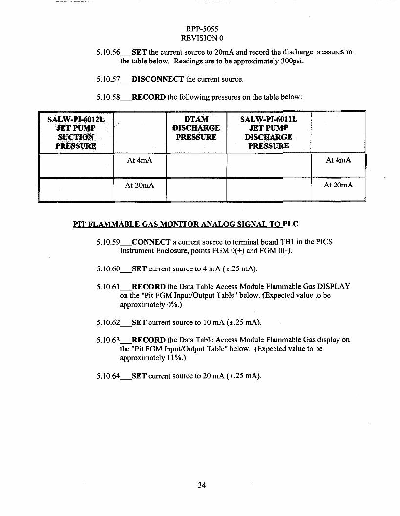
5.10.56-SET the current source to 20mA and record the discharge pressures in the table below. Readings are to be approximately 30Opsi.
5.1 0.57-DISCONNECT the current source.
5.10.58-RECORD the following pressures on the table below:
PIT FLAMMABLE GAS MONITOR ANALOG SIGNAL TO PLC
5.10.59-CONNECT a current source to terminal board TBl in the PICS Instrument Enclosure, points FGM O(+) and FGM 0(-).
5.10.60-SET current source to 4 mA (k.25 mA).
5.10.61-RECORD the Data Table Access Module Flammable Gas DISPLAY on the "Pit FGM Input/Output Table" below. (Expected value to be approximately O%.)
5.10.62-SET current source to 10 mA (?.25 mA).
5.10.63-RECORD the Data Table Access Module Flammable Gas display on the "Pit FGM Input/Output Table" below. (Expected value to be approximately 1 I%.)
5.10.64-SET current source to 20 mA (+.25 mA).
34

Rep-5055 REVISION 0
5.10.65-RECORD the Data Table Access Module Flammable Gas display on the "Pit FGM Input/Output Table" below. (Expected value to be approximately 30%.)
5.10.66-DISCONNECT the current source.
DOME SPACE FLAMMABLE GAS MONITOR ANAL,OG SIGNAL TO PLC
5.10.67-CONNECT a current source to terminal board TB1 in the PICS Instrument Enclosure, points FGM 1(+) and FGM 1(-).
5.10.68-SET current source to 4mA (+/- .25mA).
5.10.69-RECORD the Data Table Access Module Flammable Gas DISPLAY on the "Dome Space FGM Input/Output Table" below. (Expected value to be approximately O%.)
5.10.70-SET current source to 10 mA (t.25 mA).
5.10.71-RECORD the Data Table Access Module Flammable Gas display on the "Dome Space FGM InpuVOutput Table" below. (Expected value to be approximately 1 l%.)
5.10.72-SET current source to 20 mA (i.25 mA).
35

RPP-5055 REVISION 0
5.10.73-RECORD the Data Table Access Module Flammable Gas display on the "Dome Space FGM Input/Output Table" below. (Expected value to be approximately 30%.)
5.10.74-DISCONNECT the current source.
THERMOCOUPLE INPUTS TO PLC
5.10.75-WARM thermocouple SALW-TE-6004L, located in the Instrument Enclosure.
5.10.76-VERIFY Data Table Access Module displays a changed temperature.
Engineer Signature Date
5.10.77-VERIFY SALW-TE-6004L temperature decreases after heat source removed.
5.10.78-WARM thermocouple SALW-TE-6003L, located in INSTRUMENT AIR ENCLOSURE.
5 . 1 0 . 7 9 V E R I F Y Data Table Access Module displays a changed temperature.
Engineer Signature Date
5.10.80-VERIFY SALW-TE-6003L temperature decreases after heat source removed.
36

FWP-5055 REVISION 0
5.10.81-CONNECT a thermocouple probe to the intrinsic side of top thermocouple module (MTL 3081) in the Intrinsic Safe Panel. (This will simulate pump temperature.)
5.10.82-WARM the connected thermocouple probe.
5.10.83-VERIFY Data Table Access Module displays a changed temperature.
Engineer Signature Date
5.10.84-VERIFY the connected probe temperature decreases after heat source removed.
5.10.85-DISCONNECT the temperature probe.
5.10.86-CONNECT a thermocouple probe to the second thermocouple module in the Intrinsic Safe panel. (This will simulate jumper temperature.)
5.10.87-WARM the thermocouple probe.
5.10.88-VERIFY Data Table Access Module (screen 25)displays a changed temperature
Engineer Signature Date
5.10.89-VERIFY SALW-TE-6002L temperature decreases after heat source removed.
5.10.90-DISCONNECT the temperature probe.
RECIRCULATION FLUSH PRESSURE SIGNAL TO PLC
5.10.91-CONNECT a current source to points RFPT+ and RFPT- at the intrinsic side terminal board in the Intrinsic Safe panel. (Set the current source to “TRANSMITTER SIMULATE.”
5.10.92-SET the current source to 4mA.
5.10.93-SLOWLY increase the current output until an alarm on the DTAh4 for High Recirc. Flush Pressure(a1arm 9) occurs. (Approx. 12.5mA.)
37

RPP-5055 REVISION 0
5.10.94-ACKNOWLEDGE alarm.
5 . 1 0 . 9 5 V E R I F Y the pressure on the DTAM for RFPT is approximately 15psi.
5.10.96-DECREASE the current source to approximately 4mA.
5.10.97-VERIFY the High Recirc. Flush Pressure alarm clears on the DTAM.
5.10.98-DISCONNECT the current source.
5.10.99-VERIFY a “RFPT SIGNAL LOSS” alarm (14) occurs.
5.10.100 - ACKNOWLEDGE the alarm.
JUMPER FLUSH PRESSURE SIGNAL TO PLC
5.10.101 - CONNECT a current source to points JFPT+ and JFPT- at the intrinsic side terminal board in the Intrinsic Safe panel.
5.10.102 - SET the current source to 4mA.
5.10.103 - SLOWLY increase the current output until an alarm on the DTAM for High Flush Pressure(a1arm 3) occurs and the BLUE light on the instrument panel is ON. (Approx. 12.5mA.)
5.10.104 - ACKNOWLEDGE alarm.
5.10.105 - VERIFY the pressure on the DTAM for JFPT is approximately 1 5psi.
5.10.106 - DECREASE the current source to 4mA.
5.10.107 - VERIFY the High Flush Pressure alarm clears on the DTAM and the BLUE light turns OFF.
5.10.108 - DISCONNECT the current source.
5.10.109 - VERIFY a “JFPT SIGNAL LOSS’ alarm (16) occurs.
5.10.110 - ACKNOWLEDGE the alarm
38

RPP-5055 REVISION 0
5.10.1 11 Engineer VERIFY that section 5.10 is complete by SIGNING below.
Engineer Signature Date
5.10.1 12 Quality Assurance Inspector VERIFY that section 5.10 is complete by signing below.
Quality Assurance Inspector Signature Date
5.11 DISCRETE SIGNAL INPUTS TO PLC AND DTAM
NOTE: The DIP switches on the Intrinsic Safe Panel may require changing in order to get the proper responses for LS-I and LS-2.
JR-1 VALVE POSITION (LS-1LS-2) INPUT
5.11.1 __ CONNECT a normally closed transducer across the LS-1+ and LS- 1- and a normally open transducer across the LS-2+ AND LS-2- points on the intrinsic safe terminal board in the Intrinsic Safe panel.
5.11.2 - ACTUATE both transducers by placing a piece of steel in front of the each transducer face.
5.11.3 - VERIFY the JR-1 valve indicates "norm" at the Data Table Access Module.
5.11.4 - REMOVE the metal from in front of the LS-1 switch installed in the above step.
5.11.5 __ VERIFY the JR-1 valve indicates "NON-PROCESS" at the Data Table Access Module and address N20:32/0 is actuated on ladder 5 (rung 89).
5.11.6 - REMOVE the metal from in front of the LS-2 switch.
5.11.7 - VERIFY the JR-1 valve still indicates "NON-PROCESS" at the Data Table Access Module and address N20:32/1 is actuated on ladder 5 (rung 91).
5.11.8 - REPLACE the metal in front of the LS-2 and the LS-1 transducers.
39

RPP-5055 REVISION 0
5.11.9 - VERIFY the JR-1 valve indicates “ norm” at the Data Table Access Module and addresses N20:32/0 and N20:32/1 are clear on ladder 5 (rungs 89 and 91).
5.1 1.10-REMOVE the transducers.
LOW PRESSURE INTERLOCK (PS-1) INPUT
5.1 1.1 1-CONNECT a normally closed switch across points PS-I-NO and PS- I-1(H) at the intrinsic safe terminal board in the Intrinsic Safe panel.
5.1 1.12-VERIFY the GREEN light on the instrument panel is ON
5.1 1 . 1 3 A P P L Y software forces to allow the pump to start.
5.1 1.14-PRESS the pump start from DTAM.
5.1 1.15-VERIFY the RED light on the instrument panel is ON and the GREEN light is OFF.
5.11.16-OPEN the PS-1 switch.
5.1 1 .17-VERIFY that the amber light on the instrument panel turns ON immediately after the switch is open.
5.1 1.18-VERIFY a “XFR Pressure LOW’ alarm (alarm 1) occurs at the DTAM and a pump shutdown occurs indicated by the horn sounding, strobe flashing, shutdown alarm on the DTAM, the red light turning OFF, and the green light turning ON. ACKNOWLEDGE alarms at Data Table Access Module to verify the various alarms.
5.11.19-CLOSE the PS-1 switch to clear the “XFRPRESSURE LOW’ alarm and turn OFF amber light.
5.1 1.20-REMOVE the test switch.
5.1 1.21-LEAVE the forces in place for the high pressure test.
HIGH PRESSURE INTERLOCK (PS-1-1) INPUT 5.1 1.22-CONNECT a normally closed switch at points PS-1-NC and PS-1-
1(H) at the intrinsic safe terminal board in the Intrinsic Safe panel.
5.1 1.23-PRESS the pump start from DTAM.
5.11.24 -VERIFY the RED light on the instrument panel is ON and the GREEN light is OFF.
40

RPP-5055 REVISION 0
5.1 1.25-OPEN the switch across the PS-1-1 points.
5.1 1.26-VERIFY a “XFR Pressure HIGH’ alarm (alarm 2) at the DTAM, and a pump shutdown occurs indicated by the horn sounding, strobe flashing, shutdown alarm on the DTAM, the red light turning OFF, and the green light turning ON after a 3 second delay. ACKNOWLEDGE the alarms at the DTAM to verify the various alarms.
5.1 1.27-DISCONNECT the switch.
5.1 1.28-REMOVE the software forces.
DILUTION TANK NO FLOW INPUT
5.1 1.24-PLACE a normally closed switch across terminal points DIL-F and CKTSH-A on terminal board TB4 in the Instrument Cabinet.
5.1 1.25-VERIFY no dilution tank no flow alarm on the DTAM (alarm 35, screen 135).
5.1 1.26-OPEN the switch at TB4.
5.1 1.27-VERIFY a dilution tank no flow alarm on the DTAM.
5.1 1 .28ACKNOWLEDGE the alarm.
5.1 1.29-CLOSE the switch.
5.1 1.30-VERIFY alarm clears.
5.1 1.31-DISCONNECT the switch.
FLAMMABLE GAS MONITOR INPUT
5.1 1.32-CONNECT a normally closed switch to points FGM and CKTSH-A on terminal board TB 4 in the instrument cabinet.
5.1 1.33-VERIFY no FGM interlock alarm on the DTAM (alarm 22).
5.1 1.34-OPEN the switch
5.1 1.35-VERIFY an FGM alarm on the DTAM.
5.1 1.36-ACKNOWLEDGE the alarm.
41

RF'P-5055 REVISION 0
5.1 1.37-CLOSE the switch.
5.1 1.38-VERIFY the FGM alarm clears.
5.11.39 -LEAVE the switch connected for the Heat Trace check.
HEAT TRACE CONTROL FOR PUMP AND JUMPER
5.1 1.40-VERIFY that heat trace relays HT-1 and HT-2 are deenergized by checking for zero voltage across points 2 and 7 at each relay.
5.1 1.41-VERIFY zero voltage at TB12 between HT-I and CKT3-N.
5.1 1.42-TURN ON heat trace from DTAM to actuate relays HT-I and HT-2.
5.1 1.43-CHECK for 120vac at TB-12, points HT-I and CKT3-N.
5.1 1.44-OPEN the FGM switch.
5.1 1.45-VERIFY Ovac at TB-12, points HT-1 and CKT3-N.
5.1 1.46-TURN OFF heat trace from the DTAM.
5.1 1.47-REMOVE the switch.
5.1 1.48Engineer VERIFY that section 5.1 1 is complete by SIGNING below.
Engineer Signature Date
5.1 1.49Quality Assurance Inspector VERIFY that section 5.1 1 is complete by signing below.
Quality Assurance Inspector Signature Date
42

RPP-5055 REVISION 0
5.12 HEATERS AND AIR CONDITIONER
5.12.1 __ TURN the heater ON in the air compressor cabinet. Set the thermostat high enough to allow the unit to operate.
5.12.2 __ RESET the thermostat to approximately 40 degrees F to allow the unit to turn OFF.
5.12.3 __ TURN the fan thermostat switch low to allow the fan in the air compressor cabinet to run.
5.12.4 __ RESET the fan switch to approximately 90 degrees.
5.12.5 - TURN the heater ON in the WFIE cabinet. Set the thermostat high enough to allow the unit to operate.
5.12.6 - RESET the thermostat to approximately 40 degrees F to allow the heater to turn OFF.
5.12.7 - TURN the heater ON in the Water cabinet. Set the thermostat high enough to allow the unit to operate.
5.12.8 - RESET the thermostat to approximately 40 degrees F to allow the heater to turn OFF.
5.12.9 - TURN the heater ON in the Instrument cabinet. Set the thermostat high enough to allow the unit to operate.
5.12.10-RESET the thermostat to approximately 40 degrees F to allow the heater to turn OFF.
5.12.1 1-TURN ON the air conditioner in the Instrument cabinet. Ifnecessary, remove the front grill on the unit and adjust the temperature setting lower to get the unit to operate.
5.12.12-RESET the temperature setting to approximately 90 to 95 degrees.
43

RPP-5055 REVISION 0
5.12.13Engineer VERIFY that section 5.12 is complete by SIGNING below.
Engineer Signature Date
5.12.14Quality Assurance Inspector VERIFY that section 5.12 is complete by signing below.
Quality Assurance Inspector Signature Date
44

RPP-5055 REVISION 0
5.13 LEAK DETECTION INTERLOCK CHECK
5.13.1 - Set up two buckets for leak detector testing if leak detector probes are used for testing.
NOTE - during testing.
A supply of water needs to be available to pour into the buckets
- ATP.
Pump operation will be simulated during the remainder of the
Energized circuits and leads are contained inside the cabinet. Observe appropriate -088, ELECTRICAL WORK SAFETY to avoid
5.13.2 - PERFORM or VERIFY performed the CGI dedication for the leak detector relays per HNF-4275 and WTF-1-18 and WTF-30-16.
5.13.3 - CONNECT a leak detector probe to the primary leak detector terminals at TBll in the Instrument Cabinet, points SD-IA, SD-lB, SA- lA, and SA-1B and CONNECT a leak detector probe to leak detector #1 terminals at TBll in the Instrument Cabinet, points SD-2A, SD-2B, SA- 2A, and SA-2B. IF NECESSARY remove the jumpers from the terminal block for leak detector #I .
OR
-CONNECT a normally open switch to the primary leak detector terminals at TBll in the Instrument Cabinet, points SD-lA, SD-lB, SA- IA, and SA-1B and CONNECT a normally open switch to leak detector #1 terminals at TBl 1 in the Instrument Cabinet, points SD-2A, SD-2B, SA-2A, and SA-2B. (NOTE: Connect SD-LA and SA-LA wires to one pole of the switch and SD-LB and SA-LB wires to the other pole of the 'switch.) IF NECESSARY remove the jumpers from the terminal block for leak detector #I .
5.13.4 - VERIFY no primary leak detector alarms at the DTAM (alarms 6 and 7).
5.13.5 - PLACE the primary leak detector assembly in a bucket of water or close the test switch on the primary leak detector.
45
RPP-5055 REVISION 0
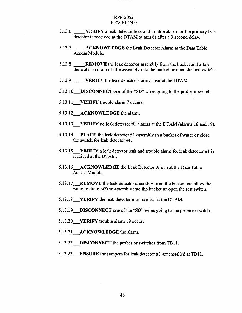
5.13.6 __ VERIFY a leak detector leak and trouble alarm for the primary leak detector is received at the DTAM (alarm 6) after a 3 second delay.
5.13.7 - ACKNOWLEDGE the Leak Detector Alarm at the Data Table Access Module.
5.13.8 - REMOVE the leak detector assembly from the bucket and allow the water to drain off the assembly into the bucket or open the test switch.
5.13.9 __ VERIFY the leak detector alarms clear at the DTAM.
5.13.10-DISCONNECT one of the “ S D wires going to the probe or switch.
5.13.1 1 V E R I F Y trouble alarm 7 occurs.
5.13.12-ACKNOWLEDGE the alarm.
5.13.13-VERIFY no leak detector #1 alarms at the DTAM (alarms 18 and 19).
5.13.14-PLACE the leak detector #1 assembly in a bucket of water or close the switch for leak detector #l .
5.13.15-VERIFY a leak detector leak and trouble alarm for leak detector #1 is received at the DTAM.
5.13.16-ACKNOWLEDGE the Leak Detector Alarm at the Data Table Access Module.
5.13.17-REMOVE the leak detector assembly from the bucket and allow the water to drain off the assembly into the bucket or open the test switch.
5.13.18-VERIFY the leak detector alarms clear at the DTAM.
5.13.19-DISCONNECT one of the “ S D wires going to the probe or switch.
5.13.20-VERIFY trouble alarm 19 occurs.
5.13.21-ACKNOWLEDGE the alarm.
5.13.22-DISCONNECT the probes or switches from TBl1.
5.13.23-ENSURE thejumpers for leak detector #1 are installed at TBl1.
46

RPP-5055 REVISION 0
5.13.24 Engineer VERIFY that section 5.13 is complete by SIGNING below.
Engineer Signature Date
5.13.25 Quality Assurance Inspector VERIFY that section 5.13 is complete by signing below.
Quality Assurance Inspector Signature Date
47

RPP-5055 REVISION 0
5.14 SKID SHUTDOWN AITER ATP
5.14.1 Drain water from water tank in the Water Cabinet by opening valve SALW-V-6030L. Catch water in a container or route to an appropriate drain.
5.14.2 Ensure the following PIC skid valves in the WFIE cabinet are OPEN,
-SAL W-V-603 5L (EQUALIZING) -SALW-V-6036L (EQUALIZING)
5.14.3 Ensure the following PIC skid valves are CLOSED.
Air Compressor cabinet: Water cabinet:
-SALW-V-6025L -SALW-V-6026L -SALW-V-6034L -SALW-V-6043L -SALW-V-6044L -SALW-V-6046L -SALW-V-6047L -SALW-V-6048L -SALW-V-6049L
WFIE Cabinet:
SALW-V-6027L SALW-V-6028L SALW-V-6029L SALW-V-6030L SALW-V-6031L SALW-V-6032L SALW-V-6037L
-SALW-V-6001 L -SALW-V-6015L -SALW-V-6002L -SALW-V-6016L -SALW-V-6003L -SALW-V-6017L -SALW-V-6004L -SALW-V-6018L -SALW-V-6005L -SALW-V-6019L -SALW-V-6006L -SALW-V-6020L -SALW-V-6007L -SALW-V-6021L -SALW-V-6008L -SALW-V-6035L LOW -SALW-V-6011L -SALW-V-6035L HIGH -SALW-V-6012L -SALW-V-6036L LOW -SALW-V-6013L -SALW-V-6036L HIGH -SALW-V-6014L
5.14.4 Ensure the following PIC skid circuit disconnects, breakers and fuses are OPEN or OFF.
-SALW-DS-6002L -SALW-DS-6003L -SALW-DS- 6004L __ SALW-DS-6OOSL
48

RF’P-5055 REVISION 0
The following breakers are in distribution panel SALW-DP-6001L:
-Breaker “MAIN” -Breaker 2 -Breaker 1 -Breaker 4 -Breaker 3 -Breaker 6 -Breaker 5 -Breaker 8 -Breaker 7 -Breaker 10 -Breaker 9 -Breaker 12 -Breaker 1 1 -Breaker 14 -Breaker 13
5.14.5 - DISCONNECT the power plug from the 48Ovac power source.
5.14.6 - ENSURE the power plug on the power cable is the correct model per H-14-103538, item 41.
5.14.7 Engineer VERIFY that section 5.14 is complete by SIGNING below.
Engineer Signature Date
5.14.8 Quality Assurance Inspector VERIFY that section 5.14 is complete by signing below.
Quality Assurance Inspector Signature Date
49

RPP-5055 REVISION 0
5.15 REDLINE INCORPORATION
5.15.1 VERIFY the redlines identified in the redline log in the Fabrication work package are incorporated into the revised drawings for skid "L".
NOTE: Redlines incorporation must meet the intent of the redline log. The redlines may not be exactly the same as marked on the working drawings. Example: If a part was added to a drawing and then it is discovered that the part already existed on the drawing, then the final incorporation may be to increase the quantity of the existing part. Drawing views may change from the redline version in order to meet drafting standards.
5.15.2 Engineer to VERIFY section 5.15 is completed by signing below.
Engineer Signature Date
5.15.3 Quality Assurance Inspector to VERIFY section 5.15 is completed by signing below.
Quality Assurance Inspector Signature Date
50

FWP-5055 REVISION 0
ACCEPTANCE TEST PROCEDURE
This page may be reproduced as necessary PAGE of-
51

RPP-5055 REVISION 0
ACCEPTANCE TEST PROCEDURE EXCEPTION LOG This page may be reproduced as necessary PAGE of-
ACCEPTANCE TEST PROCEDURE EXCEPTION LOG
Number 1 Date 1 Description
52

RPP-5055 REVISION 0
ACCEPTANCE TEST PROCEDURE EXCEPTION RECORD This page may be reproduced as necessary.
Resolution of Exception:
Date of Resolution:
Cognizant Engineer signature:
Quality Assurance signature: I
Design Authority:
53

RPP-5055 REVISION 0
ACCEPTANCE TEST PROCEDURE ACCEPTANCE RECORD
This Acceptance Test Procedure has been completed and the results, including red-line changes, exceptions, and exception resolutions, have been reviewed for compliance with the intent of the Purpose (Section 1 .O). The test results are accepted by the undersigned
~ ~~
Cognizant Engineer (Signature) (Print Name) Date
Quality Assurance (Signature) (Print Name) Date
54

RPP-5055 REVISION 0
PROCEDURE PERFORMER SIGNATURE SHEET
All personnel who will be performing, initialing and signing the procedure shall enter their printed name, signature and initials below.
55