Embed Size (px)
Citation preview

1 Octopus User Reference CE v5.00 1
Octopus User Reference
Updated: August 2017, for Community Edition version 5.00 and based onthe original Navigation Guide by.....
genoQs Machines, Stuttgart, Germany ©2009 v1.6203

2 Octopus User Reference CE v5.00 2
3 Octopus User Reference CE v5.00 3
Original Introduction
Welcome, and sincere congratulations to the purchase of your newsequencer, a genuine genoQs Machines Octopus!You now own one of the definitely finest MIDI instruments ever built. Weproudly put in your hands a device built to drive your creativity and provideyou joy for years to come.Octopus is conceived as a living instrument with long-lasting value, to helpyou search and discover new sonic territory, rewarding you with anunequalled haptics experience.We invite you to explore the capabilities of Octopus as you like and providethis manual as a start-up guide. Herein, you will recognize many knownterms and concepts. However, others may be used slightly differently fromwhat you would expect and some may be entirely puzzling.This is why we recommend that once you are over the first wave of pushingbuttons, flashing lights and turning knobs you read this guide end-to-endcarefully - and we are aware that no-one likes to read the manual.Taking a step back, we do appreciate the complexity that Octopus is able toprovide. Don't get intimidated! You will soon discover fast ways ofoperation to best suit your style and preference, the comfort zone where youare most productive.But remember that only few clicks away await things that you had neverthought of doing or achieving. This is what Octopus is about - at everystage and no matter what - you are encouraged to experiment, explore andpush the boundaries!
Gabriel Seher and Marcel AchimStuttgart, Germany 2009
Please check our web site regularly for latest news, software anddocumentationhttp://www.genoqs.net
4 Octopus User Reference CE v5.00 4
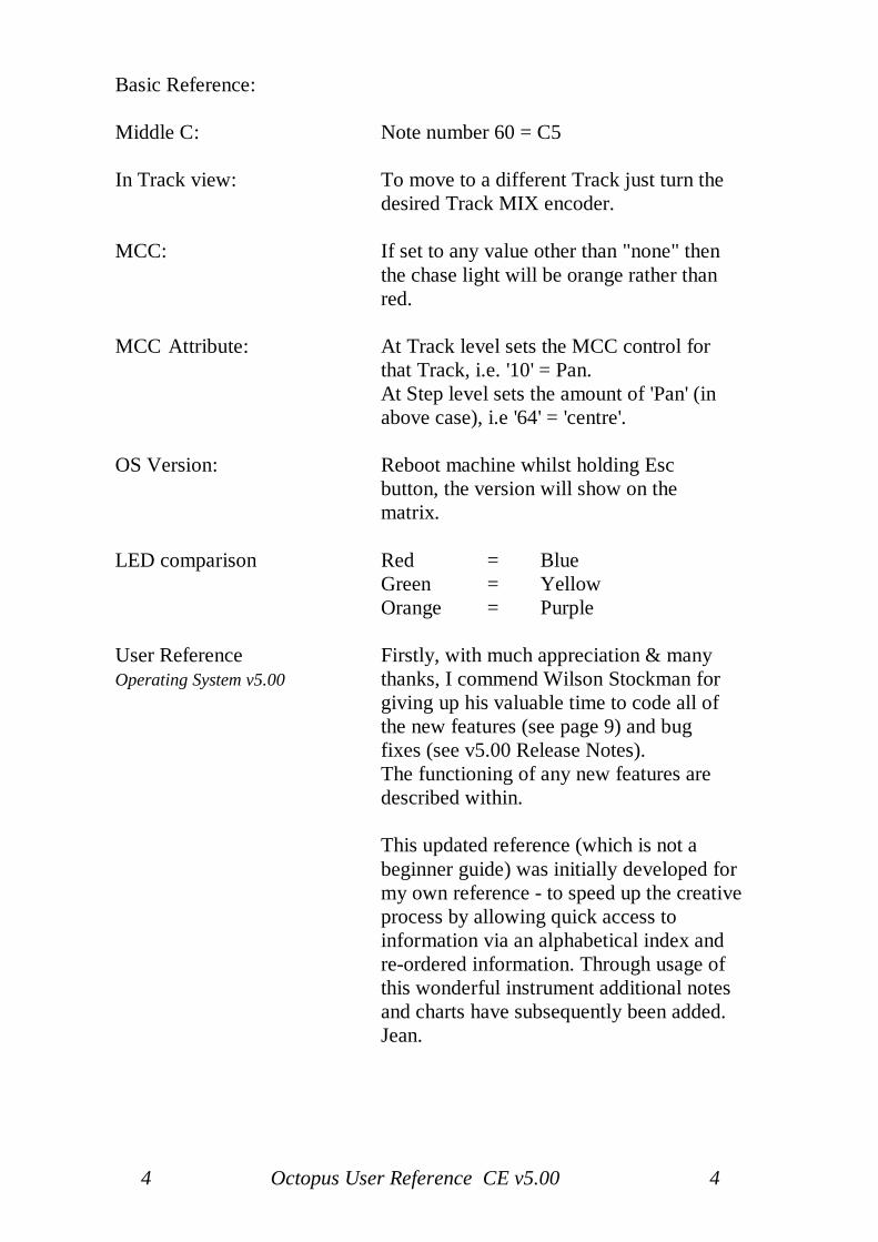
Basic Reference:
Middle C: Note number 60 = C5
In Track view: To move to a different Track just turn the desired Track MIX encoder.
MCC: If set to any value other than "none" then the chase light will be orange rather than red.
MCC Attribute: At Track level sets the MCC control for that Track, i.e. '10' = Pan.At Step level sets the amount of 'Pan' (in above case), i.e '64' = 'centre'.
OS Version: Reboot machine whilst holding Esc button, the version will show on the matrix.
LED comparison Red = BlueGreen = YellowOrange = Purple
User Reference Firstly, with much appreciation & manyOperating System v5.00 thanks, I commend Wilson Stockman for
giving up his valuable time to code all of the new features (see page 9) and bug
fixes (see v5.00 Release Notes).The functioning of any new features are described within.
This updated reference (which is not abeginner guide) was initially developed formy own reference - to speed up the creativeprocess by allowing quick access toinformation via an alphabetical index andre-ordered information. Through usage ofthis wonderful instrument additional notesand charts have subsequently been added.Jean.
5 Octopus User Reference CE v5.00 5
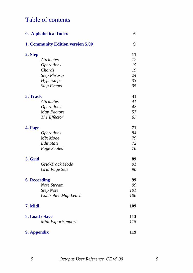
Table of contents
0. Alphabetical Index 6
1. Community Edition version 5.00 9
2. Step 11AttributesOperationsChordsStep PhrasesHyperstepsStep Events
121519243335
3. Track 41AttributesOperationsMap FactorsThe Effector
41485767
4. Page 71OperationsMix ModeEdit StatePage Scales
84797276
5. Grid 89Grid-Track ModeGrid Page Sets
9196
6. Recording 99Note StreamStep NoteController Map Learn
99101106
7. Midi 109
8. Load / Save 113Midi Export/Import 115
9. Appendix 119
6 Octopus User Reference CE v5.00 6
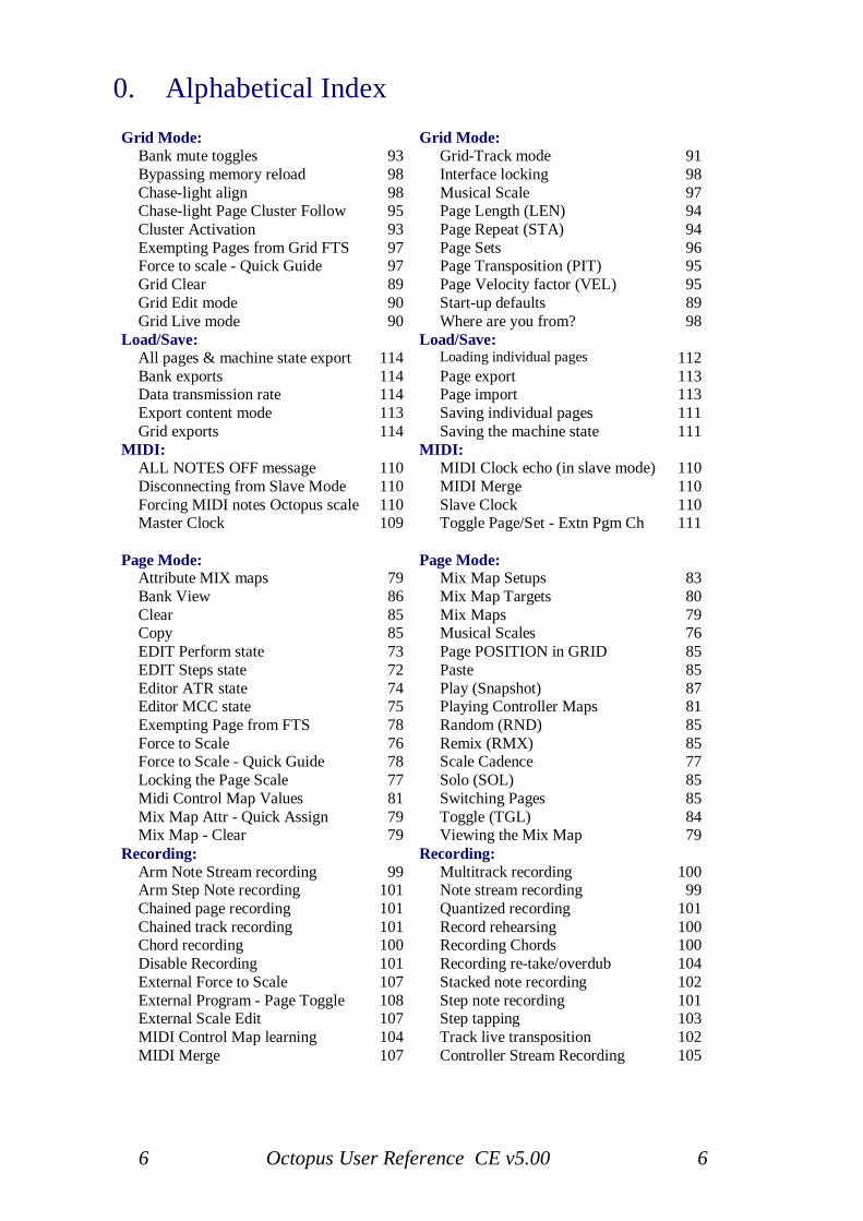
0. Alphabetical IndexGrid Mode: Grid Mode:
Bank mute toggles 93 Grid-Track mode 91Bypassing memory reload 98 Interface locking 98Chase-light align 98 Musical Scale 97Chase-light Page Cluster Follow 95 Page Length (LEN) 94Cluster Activation 93 Page Repeat (STA) 94Exempting Pages from Grid FTS 97 Page Sets 96Force to scale - Quick Guide 97 Page Transposition (PIT) 95Grid Clear 89 Page Velocity factor (VEL) 95Grid Edit mode 90 Start-up defaults 89Grid Live mode 90 Where are you from? 98
Load/Save: Load/Save:All pages & machine state export 114 Loading individual pages 112Bank exports 114 Page export 113Data transmission rate 114 Page import 113Export content mode 113 Saving individual pages 111Grid exports 114 Saving the machine state 111
MIDI: MIDI:ALL NOTES OFF message 110 MIDI Clock echo (in slave mode) 110Disconnecting from Slave Mode 110 MIDI Merge 110Forcing MIDI notes Octopus scale 110 Slave Clock 110Master Clock 109 Toggle Page/Set - Extn Pgm Ch 111
Page Mode: Page Mode:Attribute MIX maps 79 Mix Map Setups 83Bank View 86 Mix Map Targets 80Clear 85 Mix Maps 79Copy 85 Musical Scales 76EDIT Perform state 73 Page POSITION in GRID 85EDIT Steps state 72 Paste 85Editor ATR state 74 Play (Snapshot) 87Editor MCC state 75 Playing Controller Maps 81Exempting Page from FTS 78 Random (RND) 85Force to Scale 76 Remix (RMX) 85Force to Scale - Quick Guide 78 Scale Cadence 77Locking the Page Scale 77 Solo (SOL) 85Midi Control Map Values 81 Switching Pages 85Mix Map Attr - Quick Assign 79 Toggle (TGL) 84Mix Map - Clear 79 Viewing the Mix Map 79
Recording: Recording:Arm Note Stream recording 99 Multitrack recording 100Arm Step Note recording 101 Note stream recording 99Chained page recording 101 Quantized recording 101Chained track recording 101 Record rehearsing 100Chord recording 100 Recording Chords 100Disable Recording 101 Recording re-take/overdub 104External Force to Scale 107 Stacked note recording 102External Program - Page Toggle 108 Step note recording 101External Scale Edit 107 Step tapping 103MIDI Control Map learning 104 Track live transposition 102MIDI Merge 107 Controller Stream Recording 105
7 Octopus User Reference CE v5.00 7
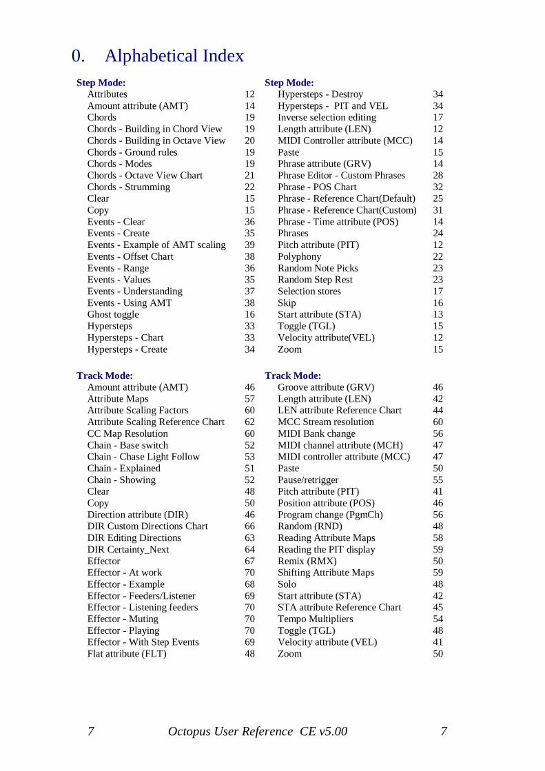
0. Alphabetical IndexStep Mode: Step Mode:
Attributes 12 Hypersteps - Destroy 34Amount attribute (AMT) 14 Hypersteps - PIT and VEL 34Chords 19 Inverse selection editing 17Chords - Building in Chord View 19 Length attribute (LEN) 12Chords - Building in Octave View 20 MIDI Controller attribute (MCC) 14Chords - Ground rules 19 Paste 15Chords - Modes 19 Phrase attribute (GRV) 14Chords - Octave View Chart 21 Phrase Editor - Custom Phrases 28Chords - Strumming 22 Phrase - POS Chart 32Clear 15 Phrase - Reference Chart(Default) 25Copy 15 Phrase - Reference Chart(Custom) 31Events - Clear 36 Phrase - Time attribute (POS) 14Events - Create 35 Phrases 24Events - Example of AMT scaling 39 Pitch attribute (PIT) 12Events - Offset Chart 38 Polyphony 22Events - Range 36 Random Note Picks 23Events - Values 35 Random Step Rest 23Events - Understanding 37 Selection stores 17Events - Using AMT 38 Skip 16Ghost toggle 16 Start attribute (STA) 13Hypersteps 33 Toggle (TGL) 15Hypersteps - Chart 33 Velocity attribute(VEL) 12Hypersteps - Create 34 Zoom 15
Track Mode: Track Mode:Amount attribute (AMT) 46 Groove attribute (GRV) 46Attribute Maps 57 Length attribute (LEN) 42Attribute Scaling Factors 60 LEN attribute Reference Chart 44Attribute Scaling Reference Chart 62 MCC Stream resolution 60CC Map Resolution 60 MIDI Bank change 56Chain - Base switch 52 MIDI channel attribute (MCH) 47Chain - Chase Light Follow 53 MIDI controller attribute (MCC) 47Chain - Explained 51 Paste 50Chain - Showing 52 Pause/retrigger 55Clear 48 Pitch attribute (PIT) 41Copy 50 Position attribute (POS) 46Direction attribute (DIR) 46 Program change (PgmCh) 56DIR Custom Directions Chart 66 Random (RND) 48DIR Editing Directions 63 Reading Attribute Maps 58DIR Certainty_Next 64 Reading the PIT display 59Effector 67 Remix (RMX) 50Effector - At work 70 Shifting Attribute Maps 59Effector - Example 68 Solo 48Effector - Feeders/Listener 69 Start attribute (STA) 42Effector - Listening feeders 70 STA attribute Reference Chart 45Effector - Muting 70 Tempo Multipliers 54Effector - Playing 70 Toggle (TGL) 48Effector - With Step Events 69 Velocity attribute (VEL) 41Flat attribute (FLT) 48 Zoom 50

8 Octopus User Reference CE v5.00 8
9 Octopus User Reference CE v5.00 9
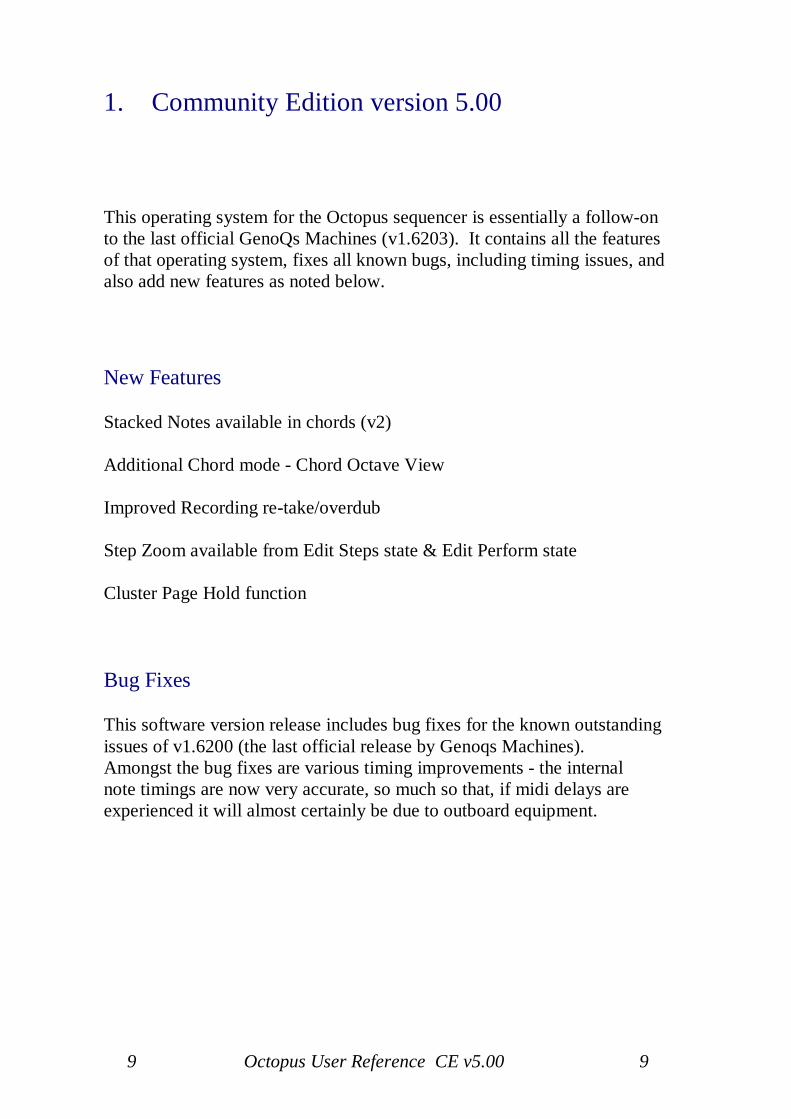
1. Community Edition version 5.00
This operating system for the Octopus sequencer is essentially a follow-onto the last official GenoQs Machines (v1.6203). It contains all the featuresof that operating system, fixes all known bugs, including timing issues, andalso add new features as noted below.
New Features
Stacked Notes available in chords (v2)
Additional Chord mode - Chord Octave View
Improved Recording re-take/overdub
Step Zoom available from Edit Steps state & Edit Perform state
Cluster Page Hold function
Bug Fixes
This software version release includes bug fixes for the known outstandingissues of v1.6200 (the last official release by Genoqs Machines).Amongst the bug fixes are various timing improvements - the internalnote timings are now very accurate, so much so that, if midi delays areexperienced it will almost certainly be due to outboard equipment.

10 Octopus User Reference CE v5.00 10
11 Octopus User Reference CE v5.00 11
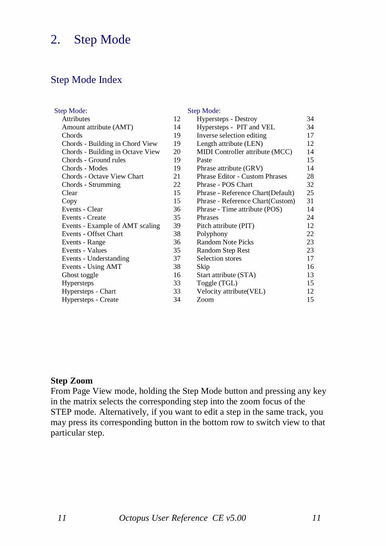
2. Step Mode
Step Mode Index
Step Mode: Step Mode:Attributes 12 Hypersteps - Destroy 34Amount attribute (AMT) 14 Hypersteps - PIT and VEL 34Chords 19 Inverse selection editing 17Chords - Building in Chord View 19 Length attribute (LEN) 12Chords - Building in Octave View 20 MIDI Controller attribute (MCC) 14Chords - Ground rules 19 Paste 15Chords - Modes 19 Phrase attribute (GRV) 14Chords - Octave View Chart 21 Phrase Editor - Custom Phrases 28Chords - Strumming 22 Phrase - POS Chart 32Clear 15 Phrase - Reference Chart(Default) 25Copy 15 Phrase - Reference Chart(Custom) 31Events - Clear 36 Phrase - Time attribute (POS) 14Events - Create 35 Phrases 24Events - Example of AMT scaling 39 Pitch attribute (PIT) 12Events - Offset Chart 38 Polyphony 22Events - Range 36 Random Note Picks 23Events - Values 35 Random Step Rest 23Events - Understanding 37 Selection stores 17Events - Using AMT 38 Skip 16Ghost toggle 16 Start attribute (STA) 13Hypersteps 33 Toggle (TGL) 15Hypersteps - Chart 33 Velocity attribute(VEL) 12Hypersteps - Create 34 Zoom 15
Step ZoomFrom Page View mode, holding the Step Mode button and pressing any keyin the matrix selects the corresponding step into the zoom focus of theSTEP mode. Alternatively, if you want to edit a step in the same track, youmay press its corresponding button in the bottom row to switch view to thatparticular step.
12 Octopus User Reference CE v5.00 12
Step attributesGoing over the front panel from left to right, you see all LEDs lit up in theSEL column.
Step velocity (VEL)The contents of the VEL row may look familiar - a number is representedhere, with the red LEDs counting the tens and the green LED pointing tothe ones value. This value may be changed in a more conventional fashionby simply turning the VEL knob.The step velocity offset may be a positive or negative number. Negativeoffsets are shown in the same manner as positive offsets, but additionallythe 3 LEDs in columns 14-16 are lit green.Please note that the total velocity of a step is determined by adding theindividual step velocity offset to the base Track velocity. This allows a widerange of velocities in a track while still giving you one place (the trackvelocity) to adjust them all up or down and still maintain the relationshipsset for each step.
Step pitch (PIT)As you may expect, the PIT row shows the pitch value for the step.The number displayed is really an offset that the step applies to the trackpitch. The combined pitch of the track and the step is shown in a musicalfashion in the inner circle.Turning the PIT knob will now cause the obvious - it will change the pitchfor the step, which you will hear once the step is played.Just as for velocity, step pitch may be a positive or negative offset relativeto the base track pitch. Negative offsets are shown in the same manner aspositive offsets, but additionally the 3 LEDs in columns 14-16 are lit green.
Step length (LEN)The same principles apply to all the other step attribute values in the page,except for the display of their values.Change the length on the step by turning its LEN knob. As you incrementthe value (turning the knob clock-wise) you will see a green dot advancingup to 11 after which the red value will be incremented.Each green increment corresponds to 1/192 of a note and each red valuecorresponds to 12/192 = 1/16 of a note.
13 Octopus User Reference CE v5.00 13
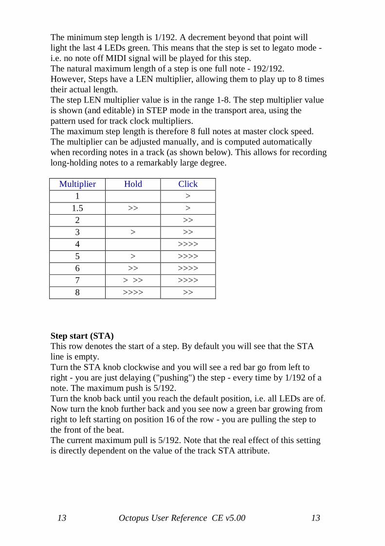
The minimum step length is 1/192. A decrement beyond that point willlight the last 4 LEDs green. This means that the step is set to legato mode -i.e. no note off MIDI signal will be played for this step.The natural maximum length of a step is one full note - 192/192.However, Steps have a LEN multiplier, allowing them to play up to 8 timestheir actual length.The step LEN multiplier value is in the range 1-8. The step multiplier valueis shown (and editable) in STEP mode in the transport area, using thepattern used for track clock multipliers.The maximum step length is therefore 8 full notes at master clock speed.The multiplier can be adjusted manually, and is computed automaticallywhen recording notes in a track (as shown below). This allows for recordinglong-holding notes to a remarkably large degree.
Multiplier Hold Click1 >
1.5 >> >2 >>3 > >>4 >>>>5 > >>>>6 >> >>>>7 > >> >>>>8 >>>> >>
Step start (STA)This row denotes the start of a step. By default you will see that the STAline is empty.Turn the STA knob clockwise and you will see a red bar go from left toright - you are just delaying ("pushing") the step - every time by 1/192 of anote. The maximum push is 5/192.Turn the knob back until you reach the default position, i.e. all LEDs are of.Now turn the knob further back and you see now a green bar growing fromright to left starting on position 16 of the row - you are pulling the step tothe front of the beat.The current maximum pull is 5/192. Note that the real effect of this settingis directly dependent on the value of the track STA attribute.
14 Octopus User Reference CE v5.00 14
Step amount (AMT)The next parameter in line would be AMT (amount). We will get into thedetails later, for now it is enough to mention that this indicates the amountto which an event programmed on this step will affect the current track.
Step phrasing (GRV)A Step may be enriched at playtime by a certain amount of notesdetermined by phrases that are pre-programmed into something we callphrases. There are three banks of 16 phrases, for a total of 48. They areroughly covering delays, rhythmic delays and note intervals respectively.As you turn the GRV encoder to the right you will see the phrase numberincrease from 1 to 16 (0 means no phrase is selected). Once 16 is reached ina bank, the colour of the pointer LED will switch to the next bank, as youcan tell from the colour.
Step phrase time compression (POS)The POS value will become visible as soon as a phrase is selected from thepool for the respective step and represents the time compression value forthe particular step phrase. A value of 8 is neutral.Values lower than 8 will speedup the playback of the phrase, while valuesgreater than 8 will slow down the playback.
Step MIDI continuous controller (MCC)The MCC value represents the amount of MIDI CC sent at this particularstep position. This of course only applies when the track is told to do so.*More on this in the TRACK view.The display uses a decimal representation similar to that used for VEL, withthe exception that is has a "void" value, indicated by 4 green LEDs in thelast positions of the track. This means that no value is sent out on that track- since 0 would be a valid value for a MIDI continuous controller.If set to any value other than "none" then the chase light will be orangerather than red.
*Attribute at Track level sets the MCC control for that Track,i.e. '10' = Pan.Attribute at Step level sets the amount of 'Pan' (in above case),i.e. '64' = 'centre'.
15 Octopus User Reference CE v5.00 15
Operations
Step toggle (TGL)Press the TGL mutator to turn the selected step on and off.
Step clear (CLR)Pressing this will recall the pre-set values for the attributes of the selectedstep and will also turn the step of, if it was turned on before.
The default Step attributes values are:VEL offset = 0PIT offset = 0LEN = 1/16STA offset = 0AMT = 0MCC = none
Step randomize (RND)This will assign most step attributes random values. The randomizationtakes place based on the actual Step value and using 50 as randomizationamount. The GRV and POS attributes that are not affected by this function.
Step zoom (ZOM)In STEP mode the LED is lit up in red. Pressing the ZOM key will exit theSTEP mode and return you back into the PAGE mode.
Step CopyWhen zoomed into a Step simply click the Copy button to copy all of thestep attributes.
Step PasteClicking the Paste button will paste the previously copied step at thecurrently selected step location. The paste operation is confirmed by thestep led which ceases to flash once the paste operation is complete.
16 Octopus User Reference CE v5.00 16
Step skipTo skip a step, press and hold the step button in question and click on theMUT button. You will see the step LED turn red. Repeat the procedure foras many steps as you would like.To un-skip a step and let it play again, just press it once and the red lightwill go off.It means that the chase-light will simply ignore the step and just move tothe next un-skipped one.
Ghost togglePress and hold pressed two or more step buttons placed in separate rows butin the same column. Let's use for instance the rows 3 and 4.Press a step in row 3 and at the same time a step in row 4 - and make sureyou do not release the buttons yet.Now toggle steps in row 3 - and you will see that the steps in the samecolumn of row 4 will be toggled as well. Or you may press steps in row 4and see the steps in row 3 toggle as well. We call this behaviour "ghosttoggle".
Exiting STEP modeIf you want to exit the STEP mode, you may press ESC anytime to findyourself back in the PAGE mode. Another option is to go back to thePAGE mode by pressing the PAGE mode button in the MODE selectorsection of the front panel.
17 Octopus User Reference CE v5.00 17
Working with step selections
Inverse step selection editingIn PAGE mode, active step selections are edited using the EDIT encodersfor the respective attribute.Additionally, when a step selection is active, the steps that are not selected,in the tracks that contain selected steps, may be edited as well,using the MIX encoders of the respective attribute.For example, assuming a step selection is active with steps selected intracks 2 and 4, the EDIT encoder PIT modifies all steps in the stepselection, while the MIX encoder will modify the pitch of all steps that arenot currently selected in the tracks 2 and 4.
Step selection storesIn PAGE mode, active step selections are stored for later recall in one of 5stores available per page. This allows to group steps and modify them atonce beyond track boundaries.The stores 1-5 are accessible while a step selection is active via the buttonslabelled 1,2,3,4,5 in the MIX TARGET row below the matrix.For example: To make a step selection hold the SEL button pressed andclick on at least one active step (green) in the page. You should see theselected step blink green and the current selection indicated by the blinkinglight in the MIX TARGET row. By default it should be 1.Now press the 2 key in the MIX TARGET area and the selection willdisappear. This is because step selection 2 is empty. Let's fill it. Press andhold the SEL button and select another step or more and watch them blink.Press the 1 in the MIX target area and you should see your previousselection blink active. You can toggle between your selections at will usingthe MIX TARGET buttons, and use the encoders to really bend yourmaterial.
A track selection occupies the same ‘virtual space’ as a step selection,however a track selection is ‘stored’ on the Sel button (Sel led red), and ifall tracks are de-selected the Sel led is off (no track selection stored). On theother hand, whilst holding the Sel button, Step Selections may be stored onlocations 1 to 5 – however, although these step selections may be de-selected they still remain in the allocated store location AND with that storelocation selected it is not possible to make a track selection!Therefore, it is important to not store step selections to all 1 - 5 locations,leave one empty, if the multiple track selection function is wanted on thatpage.

18 Octopus User Reference CE v5.00 18
Remove Step Selection StoreWith a step selection active, simply click the ESC button and the SELbutton will effectively be disengaged and the current step selection will bedeleted from the current store location.
Rebooting the sequencer will delete all step selection stores, whereas atrack selection is stored with the page.
19 Octopus User Reference CE v5.00 19
Step chords
Steps may play more than one pitch at a time, effectively forming chords.Chords can be directly programmed in, or directly recorded from, a MIDIkeyboard (see the section on MIDI IN Recording) into a step.The next section will assume we are working in STEP mode. To followalong, please make sure to enter STEP mode before we move on.To set the stage, while in STEP mode, notice the CHORD button block atthe bottom right of the front panel. By default the single note chord buttonshould be lit orange.
Chord ModesThere are two Chord modes, Chord View mode - which is the originalmode unchanged, and Octave View mode, they both display chord note databut in two different ways.As before, when zoomed into a step, holding any of the Chord buttons willdisplay the Chord notes in the inner circle - but now, the Select led isorange and clicking the Select button (whilst continuing to hold a Chordbutton), will switch to the new chord mode and the Select led will change toflashing orange - indicating you are now in chord “Octave View”- when in Chord View mode everything looks and works, as it did before- when in Octave View mode you can navigate between the chord octavelayers by clicking one of the 3 highlighted ‘octave’ buttons at the bottom ofthe inner circle, labelled MOD, SEL & CAD (default octave 1 selected)moving between 1-3 octaves respectively, the current octave will beflashing orange.Entering a Step Chord containing a note which is the same 2 or moreseveral octaves may only be done in Octave View mode.By default the original Chord View mode is shown when clicking a Chordbutton, however, it is possible to double-click any chord button to enterOctave View directly (make sure you continue to hold the Chord buttonafter the double-click). With a Chord button held its the Select button thatswitches between chord modes.
Chord ground rules for Chord View modeStep chords are formed of up to 7 notes which may range over up to threeoctaves. The chord is made up of the step pitch as the base and additionalnotes that are stacked “on top” and which are always higher than the basepitch. This means of course that changing the PIT offset of the step will alsotranspose the chord.
20 Octopus User Reference CE v5.00 20
The chord display should be read as follows: the base pitch of the stepblinks orange. Notes within one octave (12 semitones) of the base pitch willlight orange. Notes in the second octave up light green, and notes in thethird octave up light red.To toggle the notes manually in and out of the chord following togglesequence applies: off > orange > green > red > off.
Building chords in Octave View ModeIt should be noted that the note colour scheme is radically different inOctave View mode as much more information is being conveyed whenviewing the chords 'octave view'.Enter Octave View mode by double clicking (and continuing to hold) anyChord button, the Select led will flash orange. Assuming the step is turnedon and contains a single note, the root note will be flashing orange - also theMOD led will be flashing orange, the SEL & CAD leds will be lit green,this is telling you that you are view octave 1 of the chord. Other notes (inthis octave) may be turned on or off by clicking their respective buttons - ifturned on their led(s) will be orange.Now click the SEL button and its led will change to flashing orange - thismeans we are now looking at the octave above the root note (octave 2) andany notes that were entered in octave 1 will now be shown with red leds(the chord root note will be flashing red).The red led(s) simply means that the note exists in a different octave to theone you are currently viewing.Again steps can be toggled on and off, and again when turned on they willbe orange unless the note already exists in octave 1 in which case the noteled will turn green - signifying that the note is on in this octave and alsoanother octave.Now click the CAD button and its led will change to flashing orange - thismeans we are now looking at the next octave up (octave 3), which works insimilar matter to the previous octaves.The led of a note that exists in all three octave will Shine_Green and if theroot note exists in all three octave will Shine_Red.
See chart below for Octave View mode note signalling:-
21 Octopus User Reference CE v5.00 21
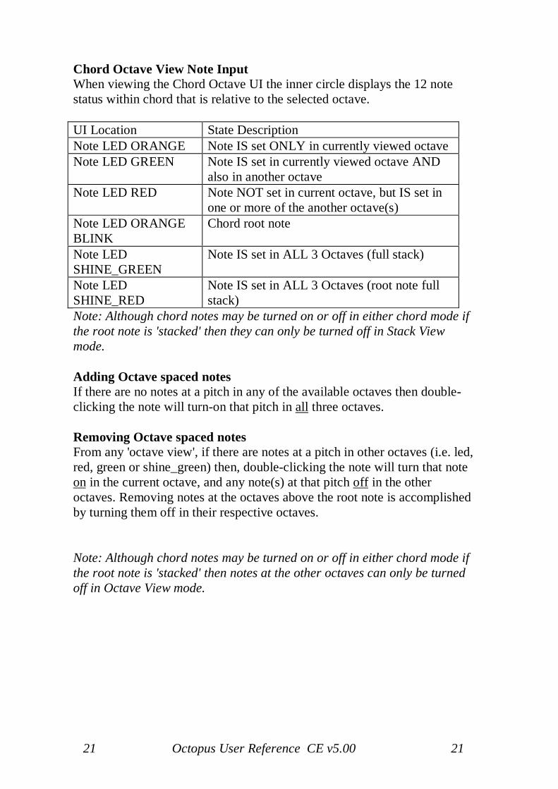
Chord Octave View Note InputWhen viewing the Chord Octave UI the inner circle displays the 12 notestatus within chord that is relative to the selected octave.
UI Location State DescriptionNote LED ORANGE Note IS set ONLY in currently viewed octaveNote LED GREEN Note IS set in currently viewed octave AND
also in another octaveNote LED RED Note NOT set in current octave, but IS set in
one or more of the another octave(s)Note LED ORANGEBLINK
Chord root note
Note LEDSHINE_GREEN
Note IS set in ALL 3 Octaves (full stack)
Note LEDSHINE_RED
Note IS set in ALL 3 Octaves (root note fullstack)
Note: Although chord notes may be turned on or off in either chord mode ifthe root note is 'stacked' then they can only be turned off in Stack Viewmode.
Adding Octave spaced notesIf there are no notes at a pitch in any of the available octaves then double-clicking the note will turn-on that pitch in all three octaves.
Removing Octave spaced notesFrom any 'octave view', if there are notes at a pitch in other octaves (i.e. led,red, green or shine_green) then, double-clicking the note will turn that noteon in the current octave, and any note(s) at that pitch off in the otheroctaves. Removing notes at the octaves above the root note is accomplishedby turning them off in their respective octaves.
Note: Although chord notes may be turned on or off in either chord mode ifthe root note is 'stacked' then notes at the other octaves can only be turnedoff in Octave View mode.
22 Octopus User Reference CE v5.00 22
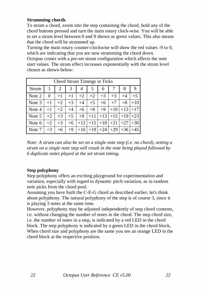
Strumming chordsTo strum a chord, zoom into the step containing the chord, hold any of thechord buttons pressed and turn the main rotary clock-wise. You will be ableto set a strum level between 0 and 9 shown as green values. This also meansthat the chord will be strummed up.Turning the main rotary counter-clockwise will show the red values -9 to 0,which are indicating that you are now strumming the chord down.Octopus comes with a pre-set strum configuration which affects the notestart values. The strum effect increases exponentially with the strum levelchosen as shown below:
Chord Strum Timings in TicksStrum 1 2 3 4 5 6 7 8 9Note 2 0 +1 +1 +2 +2 +3 +3 +4 +5Note 3 +1 +2 +3 +4 +5 +6 +7 +8 +10Note 4 +1 +2 +4 +6 +8 +9 +10 +13 +17Note 5 +2 +3 +5 +9 +11 +13 +15 +19 +23Note 6 +2 +3 +6 +12 +15 +18 +21 +27 +30Note 7 +3 +6 +9 +16 +19 +24 +29 +36 +45
Note: A strum can also be set on a single note step (i.e. no chord), setting astrum on a single note step will result in the note being played followed by6 duplicate notes played at the set strum timing.
Step polyphonyStep polyphony offers an exciting playground for experimentation andvariation, especially with regard to dynamic pitch variation, as in randomnote picks from the chord pool.Assuming you have built the C-E-G chord as described earlier, let's thinkabout polyphony. The natural polyphony of the step is of course 3, since itis playing 3 notes at the same time.However, polyphony may be adjusted independently of step chord contents,i.e. without changing the number of notes in the chord. The step chord size,i.e. the number of notes in a step, is indicated by a red LED in the chordblock. The step polyphony is indicated by a green LED in the chord block,When chord size and polyphony are the same you see an orange LED in thechord block at the respective position.
23 Octopus User Reference CE v5.00 23
Random note picks from chord poolA step whose polyphony and chord size are the same, will play a chord inthe traditional sense, as you would expect it.When step polyphony and chord size are different, the number of playedchord notes is always the smaller of the two values (i.e. chord size orpolyphony). Here the actual notes are chosen at random from a poolcomposed as follows:- When chord size is greater than polyphony, the note pool is made up byall notes that make up the chord.- When polyphony is greater than the chord size, the note pool is made upby the chord notes plus a number of rests ("empty" notes).The number of rests is given by the difference between the polyphony andthe chord size.For example: Chord is C-E-G, therefore chord size is 3 therefore:- A polyphony of 3 will consistently play the chord C-E-G.- A polyphony of 2 will play two elements picked at random from thepool {C, E, G}.- A polyphony of 5 will play 3 elements picked at random from thepool {C, E, G, rest, rest}.
Random note picks for random step restThe principle of Random note picks from chord pool can also be usedwithout a chord, i.e. on single notes, thus effectively giving the chance of anote or a rest on a specific step as follows:Zoom into a step with just one note and set the polyphony on the chordbuttons to 2, then effectively the step is {note, rest} and when playing thestep there is a 50% chance of a note being played & 50% chance of a rest,likewise if the polyphony is set to 4 the step is {note, rest, rest, rest} hencea 25% chance of the note being played.Note: Step GRV will not function as expected on a step set to random steprest.
24 Octopus User Reference CE v5.00 24
Step phrases
OverviewThere are the four main attributes (VEL, PIT, LEN, STA) of all 8 phrasenotes. In addition, there is phrase polyphony and phrase type.
The available phrase types are as follows:Type 1: Forward: notes are played in the order 1,2,3..Type 2: Reverse: notes are played in the order 8,7,6..Type 3: Random pitch programmed notes pitches are played in
random order, determined at playtime.Type 4: Random all: programmed note attributes played in
random combinations, determined at playtime.
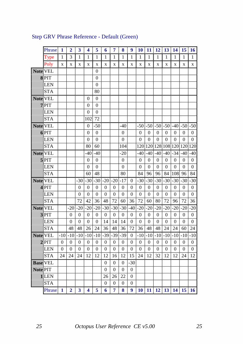
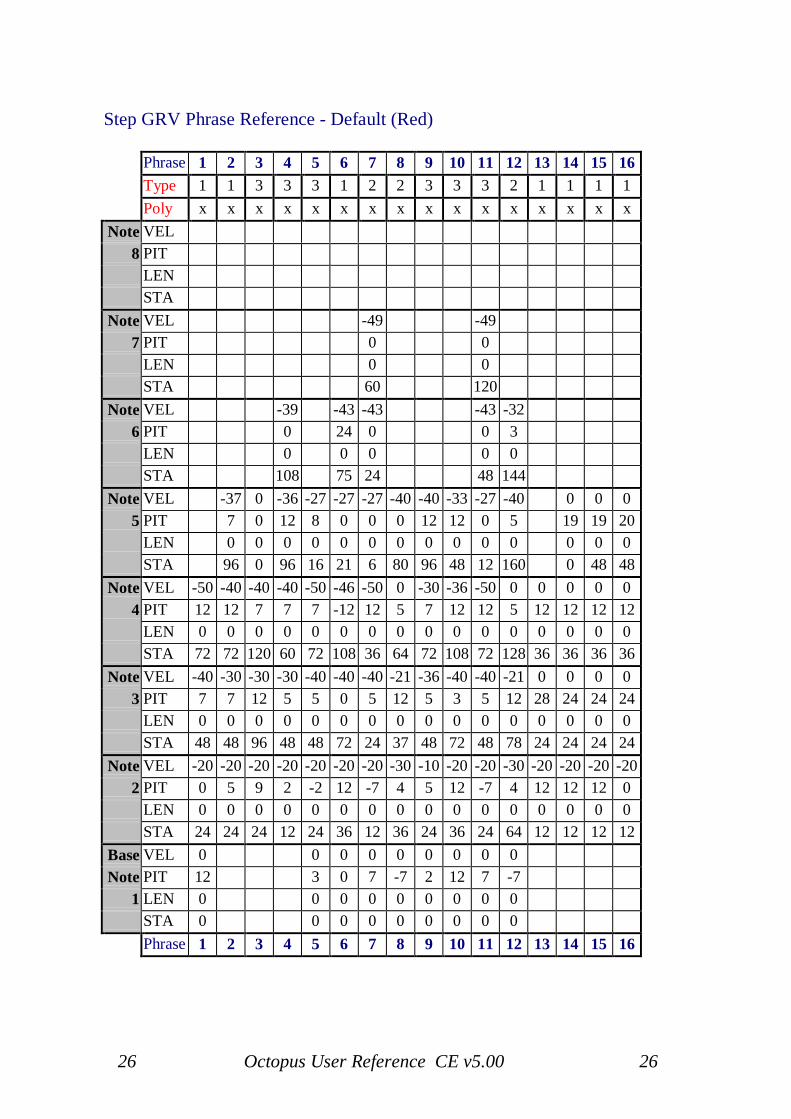
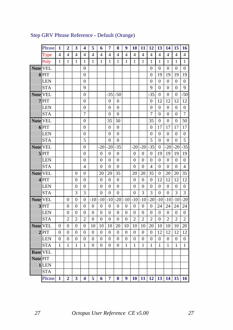
The Octopus default Step Phrases fall into the following categories:
Phrase's Green 1 to 16: Delays and rhythmic delaysPhrase's Red 1 to 16: Pitched delays and arpeggio'sPhrase's Orange 1 to 4: STA wobbles
5 to 8: VEL wobbles9 to 12: Combined STA & VEL wobbles13 to 16: Combined STA, VEL & PIT wobbles
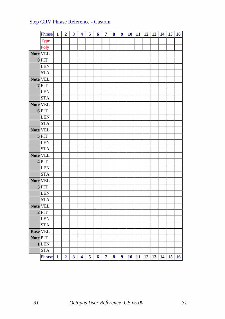
The charts below show the attributes values of each default Step Phrase. Ifthe Polyphony attribute is shown as 'x' then the phrase polyphony is notdefined, but still may be set at step level if desired.
25 Octopus User Reference CE v5.00 25
Step GRV Phrase Reference - Default (Green)
Phrase 1 2 3 4 5 6 7 8 9 10 11 12 13 14 15 16Type 1 3 1 1 1 1 1 1 1 1 1 1 1 1 1 1Poly x x x x x x x x x x x x x x x x
Note VEL 08 PIT 0
LEN 0STA 80
Note VEL 0 07 PIT 0 0
LEN 0 0STA 102 72
Note VEL 0 -50 -40 -50 -50 -50 -50 -40 -50 -506 PIT 0 0 0 0 0 0 0 0 0 0
LEN 0 0 0 0 0 0 0 0 0 0STA 80 60 104 120 120 128 108 120 120 120
Note VEL -40 -40 -20 -40 -40 -40 -40 -34 -40 -405 PIT 0 0 0 0 0 0 0 0 0 0
LEN 0 0 0 0 0 0 0 0 0 0STA 60 48 80 84 96 96 84 108 96 84
Note VEL -30 -30 -30 -20 -20 -17 0 -30 -30 -30 -30 -30 -30 -304 PIT 0 0 0 0 0 0 0 0 0 0 0 0 0 0
LEN 0 0 0 0 0 0 0 0 0 0 0 0 0 0STA 72 42 36 48 72 60 36 72 60 80 72 96 72 36
Note VEL -20 -20 -20 -20 -30 -30 -30 -40 -20 -20 -20 -20 -20 -20 -203 PIT 0 0 0 0 0 0 0 0 0 0 0 0 0 0 0
LEN 0 0 0 0 14 14 14 0 0 0 0 0 0 0 0STA 48 48 26 24 36 48 36 72 36 48 48 24 24 60 24
Note VEL -10 -10 -10 -10 -10 -39 -39 -39 0 -10 -10 -10 -10 -10 -10 -102 PIT 0 0 0 0 0 0 0 0 0 0 0 0 0 0 0 0
LEN 0 0 0 0 0 0 0 0 0 0 0 0 0 0 0 0STA 24 24 24 12 12 12 16 12 15 24 12 32 12 12 24 12
Base VEL 0 0 0 -30Note PIT 0 0 0 0
1 LEN 26 26 22 0STA 0 0 0 0Phrase 1 2 3 4 5 6 7 8 9 10 11 12 13 14 15 16
26 Octopus User Reference CE v5.00 26
Step GRV Phrase Reference - Default (Red)
Phrase 1 2 3 4 5 6 7 8 9 10 11 12 13 14 15 16Type 1 1 3 3 3 1 2 2 3 3 3 2 1 1 1 1Poly x x x x x x x x x x x x x x x x
Note VEL8 PIT
LENSTA
Note VEL -49 -497 PIT 0 0
LEN 0 0STA 60 120
Note VEL -39 -43 -43 -43 -326 PIT 0 24 0 0 3
LEN 0 0 0 0 0STA 108 75 24 48 144
Note VEL -37 0 -36 -27 -27 -27 -40 -40 -33 -27 -40 0 0 05 PIT 7 0 12 8 0 0 0 12 12 0 5 19 19 20
LEN 0 0 0 0 0 0 0 0 0 0 0 0 0 0STA 96 0 96 16 21 6 80 96 48 12 160 0 48 48
Note VEL -50 -40 -40 -40 -50 -46 -50 0 -30 -36 -50 0 0 0 0 04 PIT 12 12 7 7 7 -12 12 5 7 12 12 5 12 12 12 12
LEN 0 0 0 0 0 0 0 0 0 0 0 0 0 0 0 0STA 72 72 120 60 72 108 36 64 72 108 72 128 36 36 36 36
Note VEL -40 -30 -30 -30 -40 -40 -40 -21 -36 -40 -40 -21 0 0 0 03 PIT 7 7 12 5 5 0 5 12 5 3 5 12 28 24 24 24
LEN 0 0 0 0 0 0 0 0 0 0 0 0 0 0 0 0STA 48 48 96 48 48 72 24 37 48 72 48 78 24 24 24 24
Note VEL -20 -20 -20 -20 -20 -20 -20 -30 -10 -20 -20 -30 -20 -20 -20 -202 PIT 0 5 9 2 -2 12 -7 4 5 12 -7 4 12 12 12 0
LEN 0 0 0 0 0 0 0 0 0 0 0 0 0 0 0 0STA 24 24 24 12 24 36 12 36 24 36 24 64 12 12 12 12
Base VEL 0 0 0 0 0 0 0 0 0Note PIT 12 3 0 7 -7 2 12 7 -7
1 LEN 0 0 0 0 0 0 0 0 0STA 0 0 0 0 0 0 0 0 0Phrase 1 2 3 4 5 6 7 8 9 10 11 12 13 14 15 16
27 Octopus User Reference CE v5.00 27
Step GRV Phrase Reference - Default (Orange)
Phrase 1 2 3 4 5 6 7 8 9 10 11 12 13 14 15 16Type 4 4 4 4 4 4 4 4 4 4 4 4 4 4 4 4Poly 1 1 1 1 1 1 1 1 1 1 1 1 1 1 1 1
Note VEL 0 0 0 0 0 08 PIT 0 0 19 19 19 19
LEN 0 0 0 0 0 0STA 9 9 0 0 0 9
Note VEL 0 -35 -50 -35 0 0 0 -507 PIT 0 0 0 0 12 12 12 12
LEN 0 0 0 0 0 0 0 0STA 7 0 0 7 0 0 0 7
Note VEL 0 35 50 35 0 0 0 506 PIT 0 0 0 0 17 17 17 17
LEN 0 0 0 0 0 0 0 0STA 5 0 0 5 0 0 0 5
Note VEL 0 -20 -20 -35 -20 -20 -35 0 -20 -20 -355 PIT 0 0 0 0 0 0 0 19 19 19 19
LEN 0 0 0 0 0 0 0 0 0 0 0STA 4 0 0 0 0 0 4 0 0 0 4
Note VEL 0 0 20 20 35 20 20 35 0 20 20 354 PIT 0 0 0 0 0 0 0 0 12 12 12 12
LEN 0 0 0 0 0 0 0 0 0 0 0 0STA 3 3 0 0 0 0 3 3 0 0 3 3
Note VEL 0 0 0 -10 -10 -10 -20 -10 -10 -10 -20 -10 -10 -10 -203 PIT 0 0 0 0 0 0 0 0 0 0 0 24 24 24 24
LEN 0 0 0 0 0 0 0 0 0 0 0 0 0 0 0STA 2 2 2 0 0 0 0 0 2 2 2 0 2 2 2
Note VEL 0 0 0 0 10 10 10 20 10 10 10 20 10 10 10 202 PIT 0 0 0 0 0 0 0 0 0 0 0 0 12 12 12 12
LEN 0 0 0 0 0 0 0 0 0 0 0 0 0 0 0 0STA 1 1 1 1 0 0 0 0 1 1 1 1 1 1 1 1
Base VELNote PIT
1 LENSTAPhrase 1 2 3 4 5 6 7 8 9 10 11 12 13 14 15 16
28 Octopus User Reference CE v5.00 28
Editing step phrases
Enter The Phrase EditorTo enter the phrase editor, double click a step, and then double click theGRV button in the SEL column. The phrase editor mode is easilyrecognized, since all of the 7 chord note LEDs on the right are lit.Equally, you may access the phrase editor by entering track mode (doubleclick one of the track selectors), and then double click the GRV button onthe SEL column.
The bottom row (Row 0)The bottom row of the matrix (row 0) shows the index number of the phrasecurrently being edited, by a blinking LED of the corresponding colour. Ifyou see nothing shown there, you're looking at phrase #0, the default settingfor a step, and which has no effect, i.e. plays the step as is. Turn the main-or GRV rotary to change phrases and switch the view accordingly.The 7 green note LEDs are mostly there to tell you that they may bepressed: to set the optional phrase polyphony, press one of the note buttonsto make it blink orange. To restore the phrase to normal, full polyphony,press the blinking note button again, and the blink will disappear.
The MatrixThe matrix shows one of the four main attributes (VEL, PIT, LEN, STA) ofall 8 phrase notes together, one note per row. Row #1 shows the data forphrase note #1, row #2 shows note #2, etc.A green LED lit at the end of the row means that the phrase has a notedefined for that line. If you don't see any green LEDs lit on those lines, youknow the phrase has a zero note count. A red LED is shown there only forphrase #0, which is read-only.Top row always shows the phrase type coded as a number of orange LEDs.The available phrase types are as follows:
Type 1: Forward: notes are played in the order 1,2,3..Type 2: Reverse: notes are played in the order 8,7,6..Type 3: Random pitch programmed notes pitches are played in
random order, determined at playtime.Type 4: Random all: programmed note attributes played in
random combinations, determined at playtime.
For example, 4 orange LEDs means the phrase has type Random all, asdescribed above.
29 Octopus User Reference CE v5.00 29
MIXER BlockThe top four orange LEDs in the MIXER block indicate the attributesavailable for editing, which are VEL, PIT, LEN and STA in top-downorder. The currently active attribute is blinking orange. To select anotherattribute, simply press the associated button. This will change the contentshown in the matrix.The rotaries in the MIXER block are used to change the currently selectedattribute for the note on the matching row. The rotary of row #9 at the top isused to change the phrase type.
Mutator blockThe following buttons in the MUTATOR block are supported:
CLRThe CLR button will clear the whole phrase to empty, if the phrase was nonempty. When pressed again (in an empty phrase), it will restore to thefactory pre-set phrase.When pressed while grabbing one of the four orange attribute buttons in theMIXER block, CLR will only clear the data of the selected attribute.
RNDThe RND button will randomize the whole phrase. When pressed whilegrabbing one of the four orange attribute buttons in the MIX block, RNDwill randomize the data of the selected attribute.
CPY and PSTThe CPY and PST buttons will allow phrases to be copied and pastedbetween slots in the phrase pool. Note that phrase #0 can only be copiedfrom.
30 Octopus User Reference CE v5.00 30
EDIT Block
Some of the rotaries in the EDIT block are supported:
POSThe POS knob changes the groove of the current phrase in a very nice way.When turning to the right, it stretches the timing to the next availablestraight-, triad- or dotted version of the original, and when turned to the leftit does a similar thing by compressing the phrase tempo. This allows one totry a triad or dotted version of the phrase just by experimenting with theGRV knob.Note that if POS doesn't understand the timing of the current phrase, it usesa simple factor two multiply or division for the new groove. POS uses theSTA offset of the first non-zero phrase note to analyze the timing.
GRVThe GRV knob (like the main knob) selects another phrase from the poolfor editing.
Save Your WorkThe phrase pool is saved as part of the global Grid object, along with otherglobal data. The grid object is saved when the full machine state is saved.To save the full machine state do this:
1. Go to GRID mode.2. Stop the machine.3. Press GRID + Program.4. Wait for the progress lights to complete the circle.
Note: Best practice is to use GRV steps in a different Track to theun-GRVed steps. This will allow the GRV steps to be muted when changingthe settings.
Using Phrase Type 4 with a polyphony of 1 (or VEL of -127) will facilitateRandom Note picks when used with the PIT attribute and Random Steppick when used with the STA attribute.
31 Octopus User Reference CE v5.00 31
Step GRV Phrase Reference - Custom
Phrase 1 2 3 4 5 6 7 8 9 10 11 12 13 14 15 16TypePoly
Note VEL8 PIT
LENSTA
Note VEL7 PIT
LENSTA
Note VEL6 PIT
LENSTA
Note VEL5 PIT
LENSTA
Note VEL4 PIT
LENSTA
Note VEL3 PIT
LENSTA
Note VEL2 PIT
LENSTA
Base VELNote PIT
1 LENSTAPhrase 1 2 3 4 5 6 7 8 9 10 11 12 13 14 15 16
32 Octopus User Reference CE v5.00 32
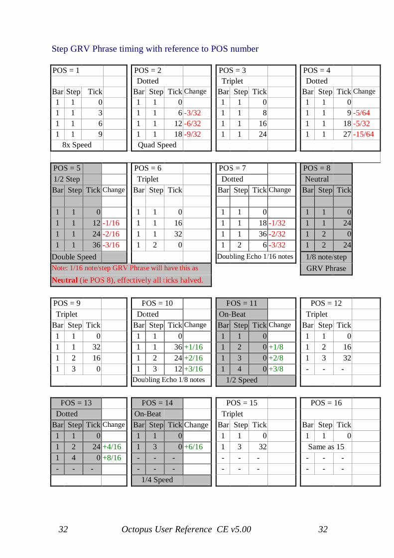
Step GRV Phrase timing with reference to POS number
POS = 1 POS = 2 POS = 3 POS = 4Dotted Triplet Dotted
Bar Step Tick Bar Step Tick Change Bar Step Tick Bar Step Tick Change1 1 0 1 1 0 1 1 0 1 1 01 1 3 1 1 6 -3/32 1 1 8 1 1 9 -5/641 1 6 1 1 12 -6/32 1 1 16 1 1 18 -5/321 1 9 1 1 18 -9/32 1 1 24 1 1 27 -15/64
8x Speed Quad Speed
POS = 5 POS = 6 POS = 7 POS = 81/2 Step Triplet Dotted NeutralBar Step Tick Change Bar Step Tick Bar Step Tick Change Bar Step Tick
1 1 0 1 1 0 1 1 0 1 1 01 1 12 -1/16 1 1 16 1 1 18 -1/32 1 1 241 1 24 -2/16 1 1 32 1 1 36 -2/32 1 2 01 1 36 -3/16 1 2 0 1 2 6 -3/32 1 2 24
Double Speed Doubling Echo 1/16 notes 1/8 note/stepNote: 1/16 note/step GRV Phrase will have this as GRV PhraseNeutral (ie POS 8), effectively all ticks halved.
POS = 9 POS = 10 POS = 11 POS = 12Triplet Dotted On-Beat Triplet
Bar Step Tick Bar Step Tick Change Bar Step Tick Change Bar Step Tick1 1 0 1 1 0 1 1 0 1 1 01 1 32 1 1 36 +1/16 1 2 0 +1/8 1 2 161 2 16 1 2 24 +2/16 1 3 0 +2/8 1 3 321 3 0 1 3 12 +3/16 1 4 0 +3/8 - - -
Doubling Echo 1/8 notes 1/2 Speed
POS = 13 POS = 14 POS = 15 POS = 16Dotted On-Beat Triplet
Bar Step Tick Change Bar Step Tick Change Bar Step Tick Bar Step Tick1 1 0 1 1 0 1 1 0 1 1 01 2 24 +4/16 1 3 0 +6/16 1 3 32 Same as 151 4 0 +8/16 - - - - - - - - -- - - - - - - - - - - -
1/4 Speed
33 Octopus User Reference CE v5.00 33
Hypersteps
Let's start with a short background, to help explain the idea of hyper- steps.Normally steps trigger notes in the following sense: they provide the start,the velocity, and the length (playtime) of the played note.
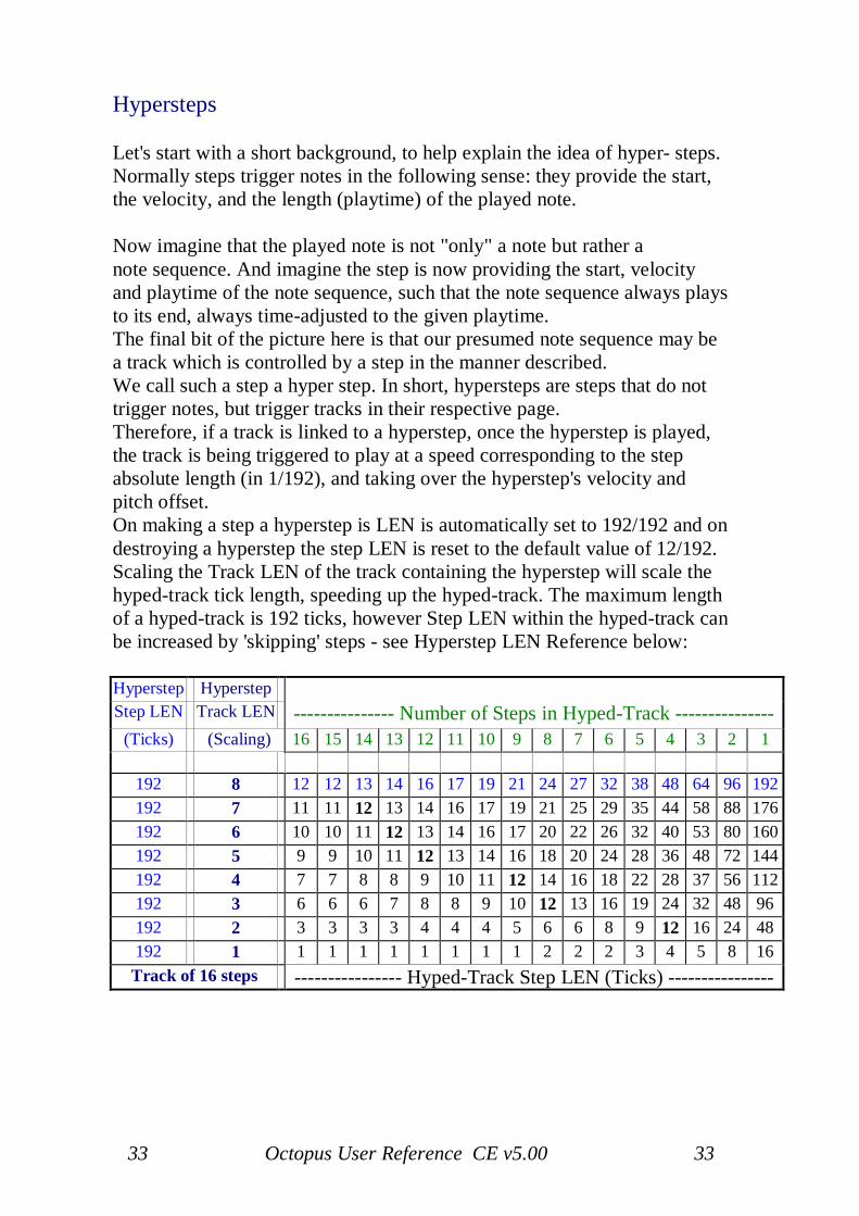
Now imagine that the played note is not "only" a note but rather anote sequence. And imagine the step is now providing the start, velocityand playtime of the note sequence, such that the note sequence always playsto its end, always time-adjusted to the given playtime.The final bit of the picture here is that our presumed note sequence may bea track which is controlled by a step in the manner described.We call such a step a hyper step. In short, hypersteps are steps that do nottrigger notes, but trigger tracks in their respective page.Therefore, if a track is linked to a hyperstep, once the hyperstep is played,the track is being triggered to play at a speed corresponding to the stepabsolute length (in 1/192), and taking over the hyperstep's velocity andpitch offset.On making a step a hyperstep is LEN is automatically set to 192/192 and ondestroying a hyperstep the step LEN is reset to the default value of 12/192.Scaling the Track LEN of the track containing the hyperstep will scale thehyped-track tick length, speeding up the hyped-track. The maximum lengthof a hyped-track is 192 ticks, however Step LEN within the hyped-track canbe increased by 'skipping' steps - see Hyperstep LEN Reference below:
Hyperstep HyperstepStep LEN Track LEN --------------- Number of Steps in Hyped-Track ---------------
(Ticks) (Scaling) 16 15 14 13 12 11 10 9 8 7 6 5 4 3 2 1
192 8 12 12 13 14 16 17 19 21 24 27 32 38 48 64 96 192192 7 11 11 12 13 14 16 17 19 21 25 29 35 44 58 88 176192 6 10 10 11 12 13 14 16 17 20 22 26 32 40 53 80 160192 5 9 9 10 11 12 13 14 16 18 20 24 28 36 48 72 144192 4 7 7 8 8 9 10 11 12 14 16 18 22 28 37 56 112192 3 6 6 6 7 8 8 9 10 12 13 16 19 24 32 48 96192 2 3 3 3 3 4 4 4 5 6 6 8 9 12 16 24 48192 1 1 1 1 1 1 1 1 1 2 2 2 3 4 5 8 16
Track of 16 steps ---------------- Hyped-Track Step LEN (Ticks) ----------------
34 Octopus User Reference CE v5.00 34
By 'Scaling' the Hyperstep Track LEN the Hyped-Track can be speeded up(8, neutral - 1, fastest). Scaling 9 - 12 will get the same result as 8 and 13- 16 will get the same result as 1 - 4 respectively.
Note: By muting steps in the hyperstep track the number of steps played inthe hyped-track is also reduced. However, this can also be manipulated byLEN scaling - either by changing the track LEN of the hyperstep track orchanging the note LEN of the hyperstep.
Hyperstep PIT and VELIn addition to a ‘Hypedtrack’ being controlled by the Hyperstep LEN, theHyperstep PIT and VEL also control the hypedtrack pitch and velocity.Therefore, the hypedtrack will assume both the pitch and the velocityvalues of the hyperstep.Changes to the hyperstep PIT and VEL will influence the hypedtrack inreal-time – hence changing the hyperstep PIT or VEL offsets will influencethe hypedtrack steps at the position of the chase light !
Engaging hyperstepsTo use hypersteps, go to PAGE mode, hold a track selector down, and at thesame time designate the hyperstep in the matrix, in a row other than thetrack's (by pressing it down as well). You will see that both the trackselector and the hyperstep start flashing between green & orange.There can be multiple hypersteps in one track (pointing to different hyped-tracks) but a hyped-track can only have one associated hyperstep.Hypersteps cannot be 'nested', i.e. it is not possible to have a hyperstepwithin a hyped-track.
Destroying hyperstepsTo disengage or destroy the hyperstep of a hyped track, hold the respectivetrack selector of the hyped track pressed and then press any step button inthe matrix row of the hyped track. The association between the step and thetrack will be removed.
35 Octopus User Reference CE v5.00 35
Step events
Steps may be used to generate so called events. Events are simplyautomated changes that happen at runtime. In general terms, an event is aprogrammed change of the attributes of a track and is attached to a step. Alltrack attributes may be modulated by events.The finer definition is however, that for the DIR, POS, and MCH events thetrack attribute value changes, while in the case of the other attributes, (VEL,PIT, LEN, STA, AMT, GRV, and MCC) what changes is really theattribute map factor of any steps having offsets from the track value.Please refer to the section on attribute maps for details.
Creating eventsTo create an event, double click on a step to zoom into it, and select one ofthe attributes in the SEL column. As discussed earlier, initially these are alllit, waiting to be selected. Once selected as an event, they will blink.You will notice that some are coloured orange, some green. The orangeattributes indicate that their events will influence the attribute map factor,while the events for the green ones will change the attribute value directly.
The step led of an event will be orange.
Note: If the 'Play' button is set to flashing orange (Play Mode) then theevents will not be retained when the sequencer is 'stopped'.
Set event valuesThe amount (AMT) value of the step determines the change in the trackattribute every time the step is played.In the case where the set amount is larger than the possible value range ofthe target, a modulo operation will be carried out to bring it into the range.Note that the changes can be positive or negative, according to the amountvalue.
Random event valuesRandom event values, via a non-zero value of the GRV attribute for the stepgenerating an event, is a disabled feature in version 1.6203 and later.
36 Octopus User Reference CE v5.00 36
Clearing eventsEvents may be cleared from a track by zooming into the step and pressingthe flashing SEL attribute button so it is solid orange or green again.
Event range settingsSometimes it makes sense to limit the range in which the event changeoccurs to a value below the size of its natural range. Those MAXIMUMvalues are 17 for each of the attribute map factors, 16 for DIR and 32 forMCH.POS Step Event changes the Track POS, not the Step POS(GRV)DIR Step Event will change on the following step (this is only relevantwhen using a custom DIR with multiple steps per slice).
To change the size of the interval used by events, proceed as follows:go into STEP mode, i.e. zoom into your respective step. Activate an eventand you should see the current size of the event interval for the selectedattribute displayed numerically in the numeric field of the outer circle. Usethe main rotary to adjust it to your desire.What you should notice is that the changes produced by the events will bebound between the base value of the track for that attribute and the sum ofthe base and the interval size.
Event executionAnother detail that may be of interest is that events will always executeexactly on the beat and not be influenced by the step's STA value to bepulled or pushed against the time line.
Step event offset resetFinally, a step AMT of 0 (zero) will discard the offset that was produced bya step event.
AMT eventsYou may have noticed that while the AMT value of a step determines theeffect an event has on its respective attribute, the AMT map factor may bemodified by events as well.By creating AMT events, you are effectively able to have dynamic changesin the actual amount of change that is being applied to an attribute mapfactor, so we will be seeing changes to the change rate!This is a powerful instrument to create evolving and to a large degreeunpredictable sequences.
37 Octopus User Reference CE v5.00 37
Understanding Step EventsStep offsets changed by Step Events are influenced by 3 things, TrackAttribute Scaling, Step Event Range and the Step Event AMT.Step Events will only influence steps whose attributes have been offset fromtheir respective track values.
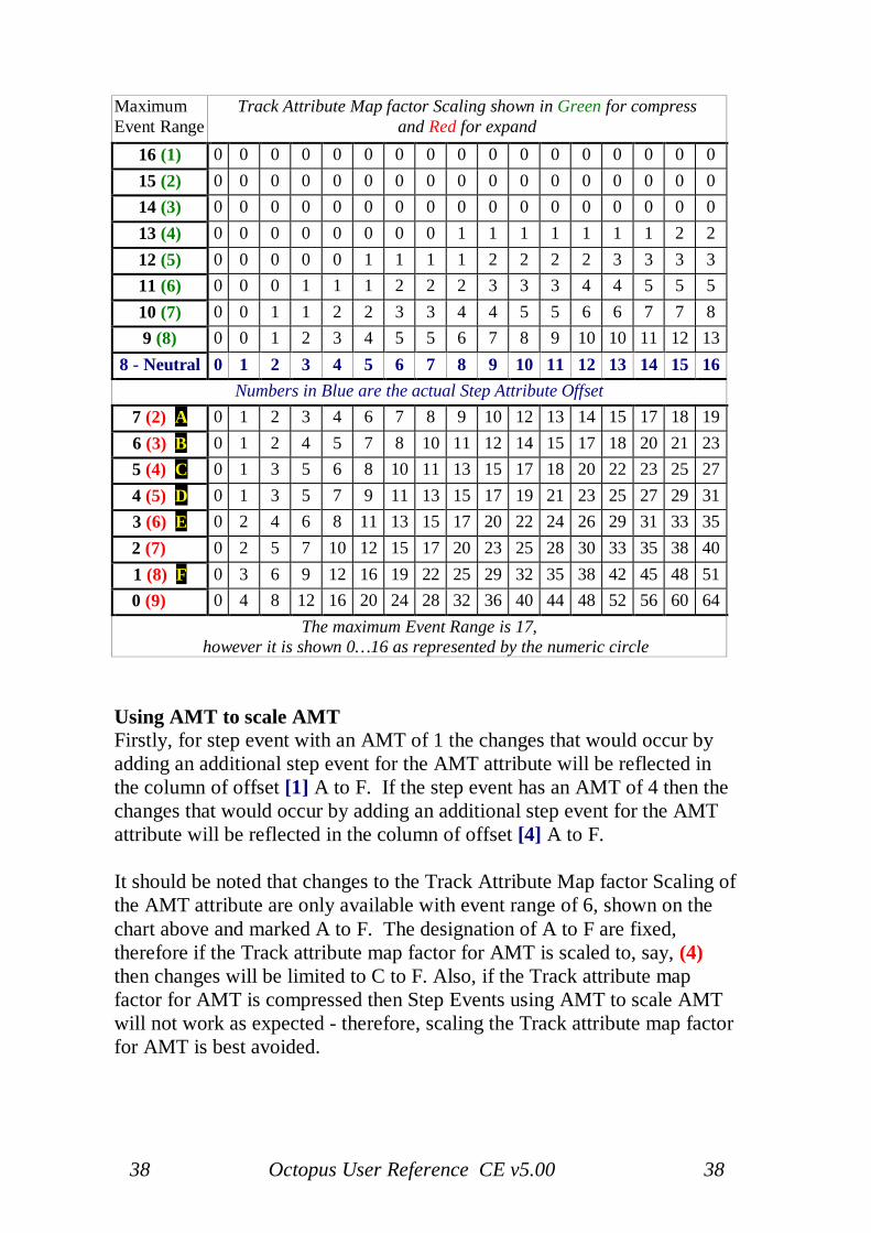
Track Attribute Scaling will affect the Step Event Range, the chart belowshows the actual step offset (in blue), the neutral value - which is the casewhen the Track Attribute has not been scaled - hence the maximum StepEvent Range will be 8 (7 to 0). If the Track Attribute has been expanded to,say, 4 (see section on Attribute maps) then effectively the 'neutral' line willbe at 5 (4) and in this case the maximum Step Event Range will be 5 (4 to0).The Track Attribute will have to be compressed to its maximum amount (1)for the full Step Event Range of 17 to be available.
Step Event Range is subordinate to Track Attribute Scaling, therefore if anattribute map has been scaling to the maximum (expanded ) amount thenstep events for that attribute will have no effect.Step Event Range sets the range by which a step event can change the trackattribute scaling.
Step Event AMT simply changes to Track Attribute Scaling (within theStep Event Range) each time the Step Event is executed.If Step Event AMT is greater than the Step Event Range then the AMT willbe divided by the Step Event Range and the remainder will be applied to theTrack Attribute Scaling amount.
Example for attributes (VEL, PIT, LEN, STA, GRV, AMT & MCC):Assume Track Attribute has not been scaled, and the Step Event Range isset to 3. With the Step Event AMT set to 0 the neutral values (shown blueon the chart below) will be applied to the attribute, if the Step Event AMTis set to +1 then the following occurs:The track attribute will be scaled by +1 each time the step event isexecuted, therefore the offset in row 7 (2) of the chart will now be applied,then row 6 (3) then row 5 (4) - as the Step Event Range is set to 3 the nextStep event will cause the offset in row 8 (neutral) to be applied. So in thisexample, if the initial step offset was '12' then the sequence of the stepoffsets would be 12, 14, 17, 20, 12, 14, 17, 20, 12 and so on.An AMT of -1 will result in the same offsets except the sequence will be inreverse order, thus, 12, 20, 17, 14, 12, 20, 17, 14, 12.
38 Octopus User Reference CE v5.00 38
MaximumEvent Range
Track Attribute Map factor Scaling shown in Green for compressand Red for expand
16 (1) 0 0 0 0 0 0 0 0 0 0 0 0 0 0 0 0 015 (2) 0 0 0 0 0 0 0 0 0 0 0 0 0 0 0 0 014 (3) 0 0 0 0 0 0 0 0 0 0 0 0 0 0 0 0 013 (4) 0 0 0 0 0 0 0 0 1 1 1 1 1 1 1 2 212 (5) 0 0 0 0 0 1 1 1 1 2 2 2 2 3 3 3 311 (6) 0 0 0 1 1 1 2 2 2 3 3 3 4 4 5 5 510 (7) 0 0 1 1 2 2 3 3 4 4 5 5 6 6 7 7 89 (8) 0 0 1 2 3 4 5 5 6 7 8 9 10 10 11 12 13
8 - Neutral 0 1 2 3 4 5 6 7 8 9 10 11 12 13 14 15 16Numbers in Blue are the actual Step Attribute Offset
7 (2) A 0 1 2 3 4 6 7 8 9 10 12 13 14 15 17 18 196 (3) B 0 1 2 4 5 7 8 10 11 12 14 15 17 18 20 21 235 (4) C 0 1 3 5 6 8 10 11 13 15 17 18 20 22 23 25 274 (5) D 0 1 3 5 7 9 11 13 15 17 19 21 23 25 27 29 313 (6) E 0 2 4 6 8 11 13 15 17 20 22 24 26 29 31 33 352 (7)..... 0 2 5 7 10 12 15 17 20 23 25 28 30 33 35 38 401 (8) F 0 3 6 9 12 16 19 22 25 29 32 35 38 42 45 48 510 (9)..... 0 4 8 12 16 20 24 28 32 36 40 44 48 52 56 60 64
The maximum Event Range is 17,however it is shown 0…16 as represented by the numeric circle
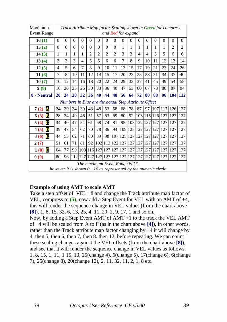
Using AMT to scale AMTFirstly, for step event with an AMT of 1 the changes that would occur byadding an additional step event for the AMT attribute will be reflected inthe column of offset [1] A to F. If the step event has an AMT of 4 then thechanges that would occur by adding an additional step event for the AMTattribute will be reflected in the column of offset [4] A to F.
It should be noted that changes to the Track Attribute Map factor Scaling ofthe AMT attribute are only available with event range of 6, shown on thechart above and marked A to F. The designation of A to F are fixed,therefore if the Track attribute map factor for AMT is scaled to, say, (4)then changes will be limited to C to F. Also, if the Track attribute mapfactor for AMT is compressed then Step Events using AMT to scale AMTwill not work as expected - therefore, scaling the Track attribute map factorfor AMT is best avoided.
39 Octopus User Reference CE v5.00 39
MaximumEvent Range
Track Attribute Map factor Scaling shown in Green for compressand Red for expand
16 (1) 0 0 0 0 0 0 0 0 0 0 0 0 0 0 0 015 (2) 0 0 0 0 0 0 0 0 1 1 1 1 1 1 2 214 (3) 1 1 1 1 2 2 2 2 3 3 4 4 5 5 6 613 (4) 2 3 3 4 5 5 6 6 7 8 9 10 11 12 13 1412 (5) 4 5 6 7 8 9 10 11 13 15 17 19 21 23 24 2611 (6) 7 8 10 11 12 14 15 17 20 23 25 28 31 34 37 4010 (7) 10 12 14 16 18 20 22 24 29 33 37 41 45 49 54 589 (8) 16 20 23 26 30 33 36 40 47 53 60 67 73 80 87 94
8 - Neutral 20 24 28 32 36 40 44 48 56 64 72 80 88 96 104 112Numbers in Blue are the actual Step Attribute Offset
7 (2) A 24 29 34 39 43 48 53 58 68 78 87 97 107 117 126 1276 (3) B 28 34 40 46 51 57 63 69 80 92 103 115 126 127 127 1275 (4) C 34 40 47 54 61 68 74 81 95 108 122 127 127 127 127 1274 (5) D 39 47 54 62 70 78 86 94 109 125 127 127 127 127 127 1273 (6) E 44 53 62 71 80 89 98 107 125 127 127 127 127 127 127 1272 (7)..... 51 61 71 81 92 102 112 122 127 127 127 127 127 127 127 1271 (8) F 64 77 90 103 116 127 127 127 127 127 127 127 127 127 127 1270 (9)..... 80 96 112 127 127 127 127 127 127 127 127 127 127 127 127 127
The maximum Event Range is 17,however it is shown 0…16 as represented by the numeric circle
Example of using AMT to scale AMTTake a step offset of VEL +8 and change the Track attribute map factor ofVEL, compress to (5), now add a Step Event for VEL with an AMT of +4,this will render the sequence change in VEL values (from the chart above[8]), 1, 8, 15, 32, 6, 13, 25, 4, 11, 20, 2, 9, 17, 1 and so on.Now, by adding a Step Event AMT of AMT +1 to the track the VEL AMTof +4 will be scaled from A to F (as in the chart above [4]), in other words,rather than the Track attribute map factor changing by +4 it will change by4, then 5, then 6, then 7, then 8. then 12, before repeating. We can countthese scaling changes against the VEL offsets (from the chart above [8]),and see that it will render the sequence change in VEL values as follows:1, 8, 15, 1, 11, 1 15, 13, 25(change 4), 6(change 5), 17(change 6), 6(change7), 25(change 8), 20(change 12), 2, 11, 32, 11, 2, 1, 8 etc.
40 Octopus User Reference CE v5.00 40
Considerations:
If the Velocity is 0 then the note is not transmitted.
When 'shifting' maps (Track POS) a step event will remain on its originalstep, it will not 'shift'.
Attributes DIR, POS & MCH are absolute, hence if DIR is 6 a Step Event of'+2' will change it to 8.
Step AMT of '0' will not reset POS, DIR or MCH values. These must bereset using the opposite amount of the values by which they were changed.
Track attribute AMT scales its own offset and is therefore best left at the'neutral' value.
DIR Step Event will change on the following step (this is only relevant whenusing a custom DIR with multiple steps per slice).
DIR will default to the Track attribute amount when the sequencer stopsand changes made using Step Events may be viewed as they occur in PageATR view and in Track Zoom.
MCH will also default to the Track attribute amount when the sequencerstops and but changes made using Step Events may only be viewed as theyoccur in Track Zoom.
POS does not restore to the start POS(ition) when stopping the sequencer.
POS Step Event changes the Track POS, not the Step POS(GRV).
41 Octopus User Reference CE v5.00 41
3. Track Mode
Track Mode Index
Track Mode: Track Mode:Amount attribute (AMT) 46 Groove attribute (GRV) 46Attribute Maps 57 Length attribute (LEN) 42Attribute Scaling Factors 60 LEN attribute Reference Chart 44Attribute Scaling Reference Chart 62 MCC Stream resolution 60CC Map Resolution 60 MIDI Bank change 56Chain - Base switch 52 MIDI channel attribute (MCH) 47Chain - Chase Light Follow 53 MIDI controller attribute (MCC) 47Chain - Explained 51 Paste 50Chain - Showing 52 Pause/retrigger 55Clear 48 Pitch attribute (PIT) 41Copy 50 Position attribute (POS) 46Direction attribute (DIR) 46 Program change (PgmCh) 56DIR Custom Directions Chart 66 Random (RND) 48DIR Editing Directions 63 Reading Attribute Maps 58DIR Certainty_Next 64 Reading the PIT display 59Effector 67 Remix (RMX) 50Effector - At work 70 Shifting Attribute Maps 59Effector - Example 68 Solo 48Effector - Feeders/Listener 69 Start attribute (STA) 42Effector - Listening feeders 70 STA attribute Reference Chart 45Effector - Muting 70 Tempo Multipliers 54Effector - Playing 70 Toggle (TGL) 48Effector - With Step Events 69 Velocity attribute (VEL) 41Flat attribute (FLT) 48 Zoom 50
Track attributes
Track pitch (PIT) and velocity (VEL)Pitch and Velocity values are displayed in the same manner we have seen inSTEP mode.The meaning of the values is interesting - they represent the base value andare to be seen in the context of the values pertaining to the steps in theparticular track.
Under the hoodWhen playing, the values of the steps in that track are added to the basetrack pitch or velocity. As a consequence, the baseline for a track is set by
42 Octopus User Reference CE v5.00 42
the track pitch and velocity. Step values are just offsets to this base.Octopus uses the convention that middle C (MIDI note #60 decimal) mapsto C5.The default Track PIT values for Tracks 9 - 0 are as follows:C3, D3, E3, G3, A3, C5, D5, E5, G5, and A5
Track LEN and STA factorsThe Length and Start rows show visually the values for the length and startfactors of a track. The STA and LEN factors are simply multipliers that areapplied to the STA and LEN offsets of the steps in a track.This means, that a high factor value will result in the effect of the STA orLEN offsets being amplified, while a low factor value will result in theeffect of the step offsets being diminished or voided altogether.In the middle setting of 8, the effect of the map is unchanged and thereforeplayed "through".In the zero setting, the STA and LEN step offsets will be ignored altogether,while in the 16 position the step offsets will be amplified by atotal factor of roughly 2.As an example, have a track play some default length notes, and simply turnthe LEN knob to the left. You will hear that the note lengths are decreasingas you go, and quite the opposite will happen as you turn the knob to theright.For the STA factor, use a track with notes playing of the beat (so you hearthe effect). Reducing the factor will play the notes closer to the "on thebeat" time, effectively quantizing the play, while increasing the factor willmove the steps further away from the on the beat position (see below).On a side note, in order to modify the actual length and start point ofa track, use the step skip option.
Note: If a Step STA is advanced (Pull), then the Step will not play if thepreceding step is skipped and a Track STA of less than 8 will have no effecton this behaviour.

43 Octopus User Reference CE v5.00 43
44 Octopus User Reference CE v5.00 44
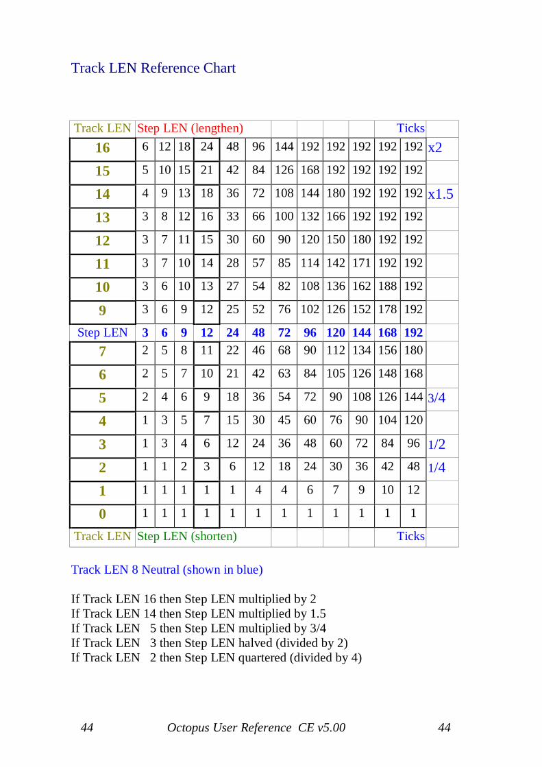
Track LEN Reference Chart
Track LEN Step LEN (lengthen) Ticks16 6 12 18 24 48 96 144 192 192 192 192 192 x215 5 10 15 21 42 84 126 168 192 192 192 192
14 4 9 13 18 36 72 108 144 180 192 192 192 x1.513 3 8 12 16 33 66 100 132 166 192 192 192
12 3 7 11 15 30 60 90 120 150 180 192 192
11 3 7 10 14 28 57 85 114 142 171 192 192
10 3 6 10 13 27 54 82 108 136 162 188 192
9 3 6 9 12 25 52 76 102 126 152 178 192
Step LEN 3 6 9 12 24 48 72 96 120 144 168 1927 2 5 8 11 22 46 68 90 112 134 156 180
6 2 5 7 10 21 42 63 84 105 126 148 168
5 2 4 6 9 18 36 54 72 90 108 126 144 3/44 1 3 5 7 15 30 45 60 76 90 104 120
3 1 3 4 6 12 24 36 48 60 72 84 96 1/22 1 1 2 3 6 12 18 24 30 36 42 48 1/41 1 1 1 1 1 4 4 6 7 9 10 12
0 1 1 1 1 1 1 1 1 1 1 1 1
Track LEN Step LEN (shorten) Ticks
Track LEN 8 Neutral (shown in blue)
If Track LEN 16 then Step LEN multiplied by 2If Track LEN 14 then Step LEN multiplied by 1.5If Track LEN 5 then Step LEN multiplied by 3/4If Track LEN 3 then Step LEN halved (divided by 2)If Track LEN 2 then Step LEN quartered (divided by 4)
45 Octopus User Reference CE v5.00 45
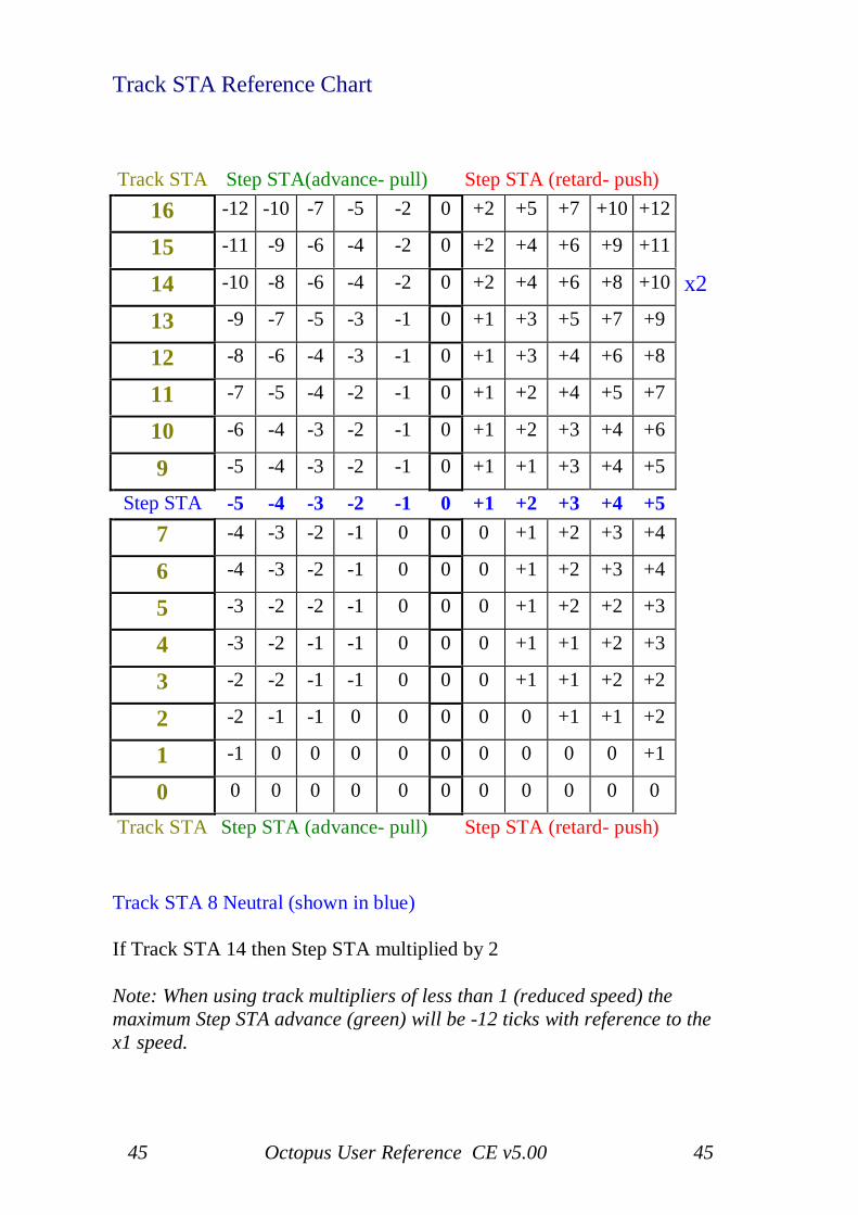
Track STA Reference Chart
Track STA Step STA(advance- pull) Step STA (retard- push)16 -12 -10 -7 -5 -2 0 +2 +5 +7 +10 +12
15 -11 -9 -6 -4 -2 0 +2 +4 +6 +9 +11
14 -10 -8 -6 -4 -2 0 +2 +4 +6 +8 +10 x213 -9 -7 -5 -3 -1 0 +1 +3 +5 +7 +9
12 -8 -6 -4 -3 -1 0 +1 +3 +4 +6 +8
11 -7 -5 -4 -2 -1 0 +1 +2 +4 +5 +7
10 -6 -4 -3 -2 -1 0 +1 +2 +3 +4 +6
9 -5 -4 -3 -2 -1 0 +1 +1 +3 +4 +5
Step STA -5 -4 -3 -2 -1 0 +1 +2 +3 +4 +57 -4 -3 -2 -1 0 0 0 +1 +2 +3 +4
6 -4 -3 -2 -1 0 0 0 +1 +2 +3 +4
5 -3 -2 -2 -1 0 0 0 +1 +2 +2 +3
4 -3 -2 -1 -1 0 0 0 +1 +1 +2 +3
3 -2 -2 -1 -1 0 0 0 +1 +1 +2 +2
2 -2 -1 -1 0 0 0 0 0 +1 +1 +2
1 -1 0 0 0 0 0 0 0 0 0 +1
0 0 0 0 0 0 0 0 0 0 0 0
Track STA Step STA (advance- pull) Step STA (retard- push)
Track STA 8 Neutral (shown in blue)
If Track STA 14 then Step STA multiplied by 2
Note: When using track multipliers of less than 1 (reduced speed) themaximum Step STA advance (green) will be -12 ticks with reference to thex1 speed.
46 Octopus User Reference CE v5.00 46
Track position (POS)The POS line will show the pattern of set steps in the track at hand.Turning the POS knob will shift the steps around, depending on the turndirection, modifying the contents of the play window, just to use the sameterms.
Track direction (DIR)This line indicates the chosen play direction for a track. Consider it as anindex into the following default mapping:1 - Forward play2 - Reverse play3 - Ping-Pong4 - Brownian, i.e. 2/3 probability forward, 1/3 probability reverse play5 - Random order6-16 - Same as 1, however: the track play directions 6-16 may also beindividually edited and changed as needed.
Track amount (AMT)AMT represents the amount of randomization applied to the track when theRMX function is called.
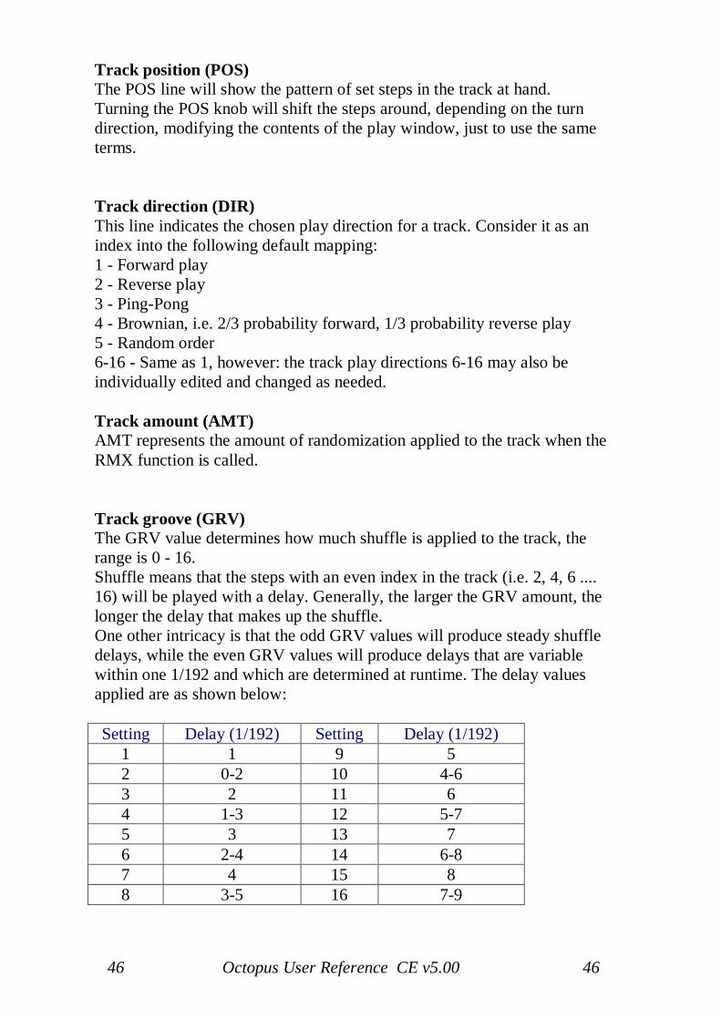
Track groove (GRV)The GRV value determines how much shuffle is applied to the track, therange is 0 - 16.Shuffle means that the steps with an even index in the track (i.e. 2, 4, 6 ....16) will be played with a delay. Generally, the larger the GRV amount, thelonger the delay that makes up the shuffle.One other intricacy is that the odd GRV values will produce steady shuffledelays, while the even GRV values will produce delays that are variablewithin one 1/192 and which are determined at runtime. The delay valuesapplied are as shown below:
Setting Delay (1/192) Setting Delay (1/192)1 1 9 52 0-2 10 4-63 2 11 64 1-3 12 5-75 3 13 76 2-4 14 6-87 4 15 88 3-5 16 7-9
47 Octopus User Reference CE v5.00 47
Track MIDI continuous controller (MCC)The MCC row determines whether or not this track sends MCC.The "none" flag is represented as four green LEDs in the positions 13- 16.The value range here is of course 0-127 and please keep in mind that avalue of 0 does indicate a valid controller value.Two exception are the BENDER and CHANNEL PRESSURE flags.The BENDER flag is shown as a red dot in position 16 of the MCC row andis indicating that the track will be sending MIDI pitch bend messagesaccording to the MCC values stored in that track's steps.The CHANNEL PRESSURE flag is indicated by two red dots in thepositions 15 and 16 of the MCC row, and is telling us that the track will besending CHANNEL PRESSURE messages according to the MCC valuesstored in that track's steps.If a track has an MCC parameter value other than "none" (i.e. the 4 greenLEDs in the positions 13-16), its chase light colour in the matrix will beorange, while the tracks whose MCC values are set to "none" have a redchase light.
Track MIDI channel (MCH)The MCH row indicates the MIDI channel for this track. Default value forall tracks is channel 1 on port 1. This is represented by a green light in the 1position.Now turn the MCH rotary encoder slowly to the right until you reach 16.Turning it once more to the right will light the LED in position 1 red. Thismeans that channel 1 on port 2 is now selected.Therefore, green 1-16 assigns a track to MIDI port 1 andred 1-16 to MIDI port 2.
Track pitch direct entryYou may have noticed that the pitch value is also indicated in the pitchinner circle on the right hand side, as you change it and otherwise. Pressingthe upper C key in the circle will transpose the track one octave up;pressing the low C key will first transpose it to the C, then one octavedown.
48 Octopus User Reference CE v5.00 48
Operations
SignalingA lit up mutator indicates that it is available. Please note that all mutatorfunctions described here are also available from the PAGE mode, as soon asa track is selected.
Track toggle (TGL)This simply toggles the track on or of. It is equivalent to muting or un-muting the track when in PAGE mode.
Track solo (SOL)Pressing the SOL button solo's the track within its page.Note that no other pages playing concurrently will be affected. Pressing itagain will un-solo the track in the page.
Track clear (CLR)CLR will recall the preset values for the selected track.Only the MIDI Channel assignment (MCH) will remain unchanged.The pitch is set to the default value of 60. Note that the factory pitchassignment can be recalled by calling the CLR mutator upon a PAGE. Ifyou are at the PAGE level and grab a Track and clear it, everything is reset.
Track randomize (RND)This will create a random step pattern in the track, not affecting the otherparameters in the track.
Track FLAT (FLT)The FLT function is used mainly to combine the pitch content of severaltracks into just one track in the same page.This function was conceived as a creative tool and not as a track space-saving feature, as it may appear at first sight. In some instances it may beuseful as such, but just in some. Please keep this in mind!FLT will only become available when you have selected two or more tracksin a page. There is a notion of a destination track, which is always the onefrom the selection with the lowest index.Applying FLT to the track selection will fill the destination track withcontent from the source tracks.
49 Octopus User Reference CE v5.00 49
For every active step in any of the source tracks, you will get thecorresponding step activated in the target track. Skipped steps will simplybe ignored.If more than one step is active in the same column across the selectedtracks, the lowest 7 pitches of active steps will get stacked to form a chordon the respective step in the destination track.Note that if source track steps contain chords already, only their base pitchwill be considered for FLT. The additional chord data in the source trackswill be ignored.The base pitch of the resulting chord will be the lowest pitch encountered inthe respective column, with the other found pitches being stacked on top.Another detail worth mentioning is the influence of FLT on the VEL, LENand STA values of the steps in the destination track. FLT always carriesover the VEL, LEN and STA attributes of the last encountered active stepfor a particular column/position inside the destination track.Also something to realize is that FLT is MIDI channel agnostic - you mayFLT different tracks playing on different channels, but the result willalways play on the MIDI channel of the destination track.With that in mind, let us suggest two best practice usage methods for FLT.Firstly, before you are applying FLT to your track selection, make sure thetarget track is muted.This way you do not get any double notes playing if the target track is set tothe same MIDI channel as any source tracks. You then can do a smoothblend-in of the new material, which may be useful when playing live forexample.Secondly, you may want to make sure the target track MIDI channel isdifferent from any of the source tracks before you apply FLT. This willeffect the obvious - the new material is going to sound fresh right away.And of course you can use both of these techniques combined to achievethe result that is best for you!
Step GRV is always reset to '0' when using FLT unless source anddestination tracks have the same GRV settings.
50 Octopus User Reference CE v5.00 50
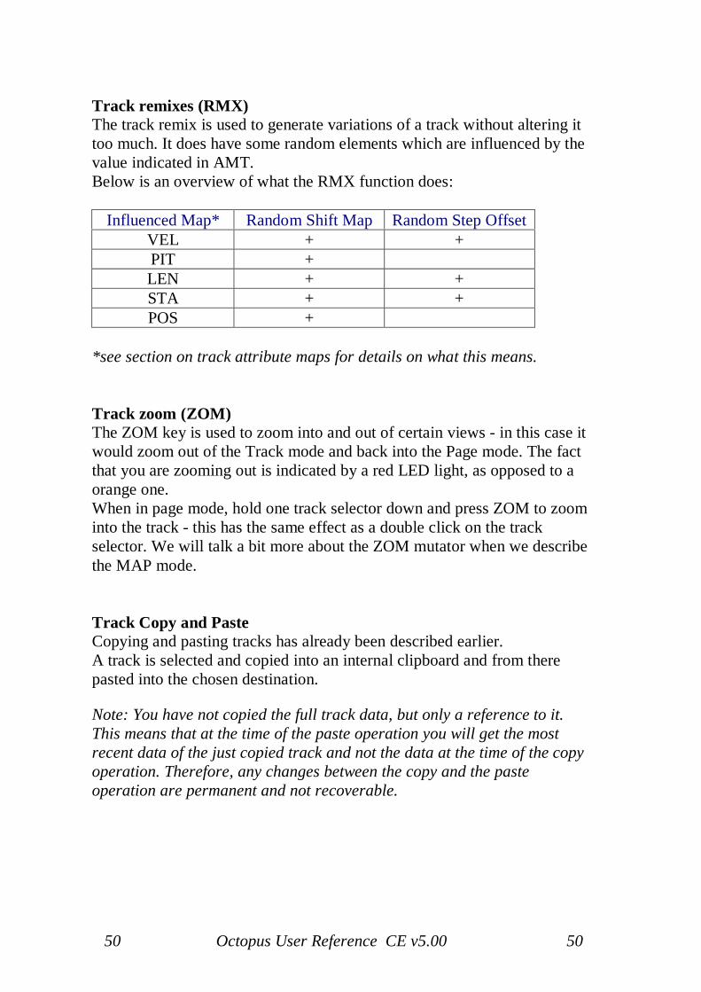
Track remixes (RMX)The track remix is used to generate variations of a track without altering ittoo much. It does have some random elements which are influenced by thevalue indicated in AMT.Below is an overview of what the RMX function does:
Influenced Map* Random Shift Map Random Step OffsetVEL + +PIT +LEN + +STA + +POS +
*see section on track attribute maps for details on what this means.
Track zoom (ZOM)The ZOM key is used to zoom into and out of certain views - in this case itwould zoom out of the Track mode and back into the Page mode. The factthat you are zooming out is indicated by a red LED light, as opposed to aorange one.When in page mode, hold one track selector down and press ZOM to zoominto the track - this has the same effect as a double click on the trackselector. We will talk a bit more about the ZOM mutator when we describethe MAP mode.
Track Copy and PasteCopying and pasting tracks has already been described earlier.A track is selected and copied into an internal clipboard and from therepasted into the chosen destination.
Note: You have not copied the full track data, but only a reference to it.This means that at the time of the paste operation you will get the mostrecent data of the just copied track and not the data at the time of the copyoperation. Therefore, any changes between the copy and the pasteoperation are permanent and not recoverable.
51 Octopus User Reference CE v5.00 51
Track chaining
Track chains explainedA track chain is simply a defined sequence of playing tracks from a page, ina given consecutive order. Track chains are always configured in PAGEmode and are useful in creating structures longer than 16 steps per page.
Playing considerationsChain configurations may or may not influence the set track parameters.Each track can be played as it is, or each track's steps may be played usingthe same set of track parameters as its base.While the pre-set chain modes were covered in the start-up section, we shallnow look closer at flexible track chain configurations.
Selecting chain membersWhile in PAGE mode, define first the group of tracks that you would like tochain by creating an appropriate selection.
Creating a track chainWhile the selection is active (blinking orange), press the 'X' (XXVIII)button to build the chain made up by these tracks.You will now see that they start playing in sequence. The play sequence isper default top to bottom (i.e. row 9 to row 0).There are cases when you will see this order changed as a result of somemore interaction with the chain structures inside a page. This has to do withthe way a chain is defined internally.
Under the hoodEvery chain has a head and a tail. The head is a track, while the tail may bemade of none, one or more other tracks.When you create a selection, the top track of a selection will be defined asthe head of the new chain, and the other selected tracks will make up thetail.Should any of the newly chained tracks have been part of a chain before(regardless if head or tail); they will be removed from their original chain(s)and added to the new one. The original chains will simply get reduced bythe tracks re-allocated to the new chain.
52 Octopus User Reference CE v5.00 52
Showing track chainsOnce a track chain has been created, you can also easily see how it is spreadacross the page.Simply select a track that is part of a chain, and you should see thefollowing information in the selector LED column.The track selected (one you have your finger on) is blinking orange.Other track members may be lit green and red. In red you can recognize thehead track of the chain, in green the other chain members that are not thehead.If the head and the selected track are the same, you will only see a blinkingorange LED.
Removing Track ChainsPress the Track button of the Track you wish to remove from the chain andclick the 'X' (XXVIII) button
What about pre-set chains?By now you may wonder, what about the pre-set chain configurations onoffer? Well, they are nothing more that pre-set chain configurations withshortcut buttons.
Track base switchYou can switch the track base of a chain from using individual track basevalues to using the track base values of the head track.Simply toggle the chain selection indicator between orange and red.orange means that tracks are being played in their natural state but inchained order.Red means that the tracks will be played taking over the values held in thehead track as a base reference.Note that this switch will work equally for pre-set and custom chainconfigurations.When changing the Track Base status any muted tracks on the page will beun-muted.
Muting chained tracksOne more thing to mention about the track base for a chain - in the contextof muting or un-muting tracks that are actually part of a chain. If the chainhead is the base of the chain, then the mute operation of any chain memberswill apply to all tracks in that chain. Note that it will be a toggle operation,so it will invert the mute pattern of the set of chained tracks.

53 Octopus User Reference CE v5.00 53
Track followThere is also an automated way of switching the track in the view - that isthe FOLLOW mode. When Follow is active and you are zoomed into atrack that is part of a chain, the view will always follow the chase light inthe respective track chain, in the sense that it will always show the trackthat is currently played by the chase-light.
Activate Follow by pressing the green follow button (XXVII) to turn it red.
Deactivate Follow by toggling it back to green.
Track tempo multipliers
54 Octopus User Reference CE v5.00 54
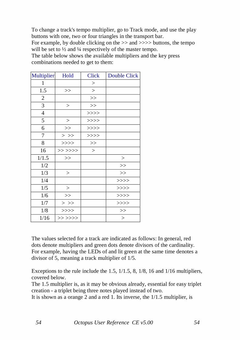
To change a track's tempo multiplier, go to Track mode, and use the playbuttons with one, two or four triangles in the transport bar.For example, by double clicking on the >> and >>>> buttons, the tempowill be set to ½ and ¼ respectively of the master tempo.The table below shows the available multipliers and the key presscombinations needed to get to them:
Multiplier Hold Click Double Click1 >
1.5 >> >2 >>3 > >>4 >>>>5 > >>>>6 >> >>>>7 > >> >>>>8 >>>> >>16 >> >>>> >
1/1.5 >> > 1/2 >> 1/3 > >> 1/4 >>>> 1/5 > >>>> 1/6 >> >>>> 1/7 > >> >>>> 1/8 >>>> >>
1/16 >> >>>> >
The values selected for a track are indicated as follows: In general, reddots denote multipliers and green dots denote divisors of the cardinality.For example, having the LEDs of and lit green at the same time denotes adivisor of 5, meaning a track multiplier of 1/5.
Exceptions to the rule include the 1.5, 1/1.5, 8, 1/8, 16 and 1/16 multipliers,covered below.The 1.5 multiplier is, as it may be obvious already, essential for easy tripletcreation - a triplet being three notes played instead of two.It is shown as a orange 2 and a red 1. Its inverse, the 1/1.5 multiplier, is
55 Octopus User Reference CE v5.00 55
shown as a orange 2 and a green 1.
The 8 multiplier is shown as a orange 4 and a red 2 LED. 1/8 is shown as aorange 4 and a green 2.
The 16 multiplier is shown as orange 4 and 2 plus a red 1, and 1/16 isindicated as a orange 4 and 2 and a green one.
Please note that during play, switching the clock multiplier is effectiveimmediately with no quantization with regard to the master tempo.Realignment of the tracks may always be done by using the ALNfunctionality available.Note that when the sequencer is playing, the changes of the track clockmultiplier are effective on the next 1/16th beat of the master clock and notimmediately. This provides better track alignment and improves the generalfeel of the sequence without the need to explicitly align after a track clockswitch.
Note: When using track multipliers of less than 1 (reduced speed) themaximum Step STA advance (green) will be 12 ticks with reference to the x1speed.
Track PauseA track can be paused by grabbing the track and pressing the Pausetransport button. Once a track is paused, hold the track button and click thePause button to advance the track by one step.To restart the track, hold the track button and click the Play button.
Note: If more than one track is paused any step advance, or restart, will beapplied to all paused tracks.
56 Octopus User Reference CE v5.00 56
Track program changes
MIDI program changeIn Track mode, you may have noticed that the Program LED is lit in orangeand the Select LED next to it is lit in green. Also, the numeric field is notshowing the global tempo value anymore, as it does in the PAGE mode.We are using that area to edit and send MIDI program changes to thechannel of the selected track.First, select the MIDI channel you would like to send the programchange on as the track MIDI channel.Next, dial in a program number, using the rotary encoder on the top right.Alternatively, you may want to key in the number of the program you wantto select. Once selected, press Program and you should hear / see theprogram change occur.A couple of side notes are necessary here. First, consider that not allsynthesizer manufacturers use the same numbering scheme for theirprograms, i.e. some start counting at 1, some at 0.However, the underlying values are always in the range 0-127.The Octopus convention is to display values in the range 0-128, wherea value of 0 means that no program change message is sent.Therefore, the program changes are numbered in the range 1-128.Secondly, a program change message will be sent every time the Programkey is pressed in TRACK mode, regardless of all other circumstances.However, if you keep the Program key pressed while turning the knob, theprogram change messages will get sent as you increase or decrease the PCnumber via the main knob.Furthermore, all program changes contained in the tracks of a page will besent (once) as soon as that page is enabled for play - either as part of acluster, or by manual intervention.
MIDI bank changesYou can also issue bank change messages. This is done simply by pressingthe Select button and turning it orange.In that case the number displayed will correspond to the bank number, andthe bank change message will get sent as soon as you press the Selectbutton again.
Bank change messages will be sent also when a page is activated for play,but not when you send program change messages from Track mode.
57 Octopus User Reference CE v5.00 57
Track attribute maps
Now that we have looked in some detail at the mutators while in TRACKmode, you may wonder what is going on to the left of the matrix - in theselector column.
The selector columnYou see that some of the LEDs are lit up, and some aren't. Each lit buttonrepresents something we call an attribute map for the track.There are attribute maps for the following attributes: VEL, PIT, LEN, STA,AMT, GRV, and MCC.
What is an attribute map?Simply put, an attribute map is a view of a particular step attribute for theentire track.Let's look at an example: the VEL map would be the view that shows youthe velocity offset of all steps of a track at once.This is true with one exception - that is the DIR line. In the case of DIR wedo not have a map per se, but rather the capability to edit the directionconfiguration for the sequencer. The details are explained in the chapterdealing with directions and we will disregard itin this section.
For example: Press VEL and you will notice that keeping it pressed willmake it blink orange and the mutator column will make CLR, RND andZOM available. Briefly - CLR and RND will affect the track VEL map andeither clear it to default value or pick a random value. Now the interestingone:
Showing attribute mapsWith the VEL selector still pressed, press the ZOM mutator to get to theMAP mode. What you now see is the VEL map of the track you areworking on.You can also enter MAP mode by double-clicking the attribute button (VELin this example).
58 Octopus User Reference CE v5.00 58
Working with attribute maps
The matrix display is built up starting at row 0 with the pattern of the trackunder consideration.Here you may toggle, select and skip steps as you would in PAGE mode, asalready described in the introductory section - also holding them andtweaking their parameters will work - but leave that for a moment to avoidconfusion.If the sequencer is playing, you also see a red chase-light in the row of thetrack currently being worked on.
Reading attribute mapsYou may think of the area made up by rows 1-9 as divided into 16 columns,one for each step represented in row 0.For each step, the column will display a bar corresponding to the value ofthe attribute whose map we are seeing. Remember that this is the attributevalue of the steps, before the steps are affected by any sort of track offset.
RepresentationFor values that can be negative or positive (VEL, PIT, STA), a zero value isrepresented by a line of LEDs on row 5. Positive values are above the lineand negative values are below.Now press any button in row 6 - as an example. You will see that the barfor the step in the column of your press will jump to the position of thebutton you have pressed.
Reading the real valuesThe real value of the step attribute offsets can be read out easily by holdingthe respective step pressed in row 0.For this purpose, you may also want to (temporarily?) use the previewmode (toggle the EDIT LED to flashing green or flashing orange), such asto not affect the toggle state of the steps you are viewing.The value is displayed in the numeric quadrant of the circle, and is alwaysshown as a sum of the track and step value for that particular attribute.Also note that while the meaning of the large circle value is changing, thepitch circle is always dedicated to showing the pitch. This is just a quick butvery powerful way of entering data for the steps of a particular track.Values may also be entered using the keys of the circle fields, i.e. entering avelocity value for a step is similar to entering a tempo value.You will see the new value reflected in the matrix display.
59 Octopus User Reference CE v5.00 59
Reading the pitch displayThe way to read the display is the following: the red dots will indicate theoctave and the green dot will indicate the note in that octave. For examplethree red dots starting at C and a green dot at G mean the pitch is G inoctave 3. Exception: two red dots starting at C and a orange dot at D meanthat the pitch is D in octave 3.
Entering pitchesEntering pitches is done by pressing the appropriate note. In order totranspose octaves use the left and right keys labelled "C".
Finding your way around the mapsThe selector column allows you to jump directly between the availabletrack maps. The mutator column allows you to use some functions on themap.CLR will restore default values, RND will choose random values for eachcolumn, and RMX allows you to call and actually observe what the RMXoperation is doing to your track parameters.ZOM, which is now lit red, will take you back to the track mode withoutun-selecting VEL, and pressing ZOM again from there will bring you againinto the map mode.
Shifting mapsThe POS knob in the Editor block is also assigned a function - turn it andyou will see your attribute map just shift around the track, without affectingthe step toggle states or the other attribute maps, but having certainlysurprising effects on your sequence.
Switching tracksYou may fetch any track into the map view by simply ticking (to the left orright - it doesn't matter) the mix encoder corresponding to the map youwant to fetch into the display.
60 Octopus User Reference CE v5.00 60
Track CC map resolution
Track CC maps have a specific property associated with them, and that isresolution.Per default, Track CC messages are sent on each step, according to therespective track and step MCC values. In addition, intermediate CCmessages may be sent between CC steps. This effectively increasesresolution of the CC stream, resulting in smoother controller flows.In MAP mode, with MCC as the selected attribute, the resolution for thecurrent track may be selected by using the chord button block.The minimum (and default) value is 1, meaning that one Track CC messageis sent per step.A value of 5 for example, denotes that 5 messages will be sent for this step.The first one right on the step, the other 4 distributed evenly across theinterval of time until the next step is triggered. The intermediate valuesautomatically create a linear slope to the next value.
Map factorsMaps are useful in the sense that we can see and edit a particular stepattribute for all steps at once.
Step attribute scalingThere is another advantage we get from maps - and that is the easyfactoring or scaling of step attribute effect on the play result.Using a scaling factor for each map of a track, we can now determine towhat degree a map is applied to the play data.
In fact, the track attributes LEN and STA themselves are really scalingfactors for the corresponding attribute maps.
Map factor settingIn all cases, the middle setting of the scaling factor will play the stepsunaffected, while tighter settings (lower values) will reduce the effect of theplayed map values. Looser settings will amplify the effect of a map on theplayed result.The value range for the map factors is numerically between 1...17, with 9being the neutral setting. Note that due to the way the display is set up, thevalues for LEN and STA shown in the TRACK mode are depicted as0.....16, with 8 being the neutral value.
61 Octopus User Reference CE v5.00 61
Lower than neutral values have a reducing effect, higher than neutral valueshave an amplifying effect.The neutral value is displayed as a orange 1, reducing values shown using agreen bar, and amplifying values shown using a red bar.
Working with map factorsIn order to view the scaling factor of a particular map, go to track mode,and press and hold the corresponding attribute selector. The numericquadrant in the outer circle will display the scaling factor.An orange dot at the 1 position indicates the middle setting. Turning themain rotary will either render a red bar up, or a green bar down, dependingon the turn direction.Note that the map factors may also be accessed directly from the MAPmode. Use the main rotary encoder to modify the respective value.
In UseThe Scaling Factor will only effect 'offsets', therefore steps that arenot offset from the Track attributes will not be changed - with theexception of DIR, POS and MCH.
In Use with Step EventsStep Events are changes to the Scaling Factor and again thescaling factor changes will only effect 'offsets'.
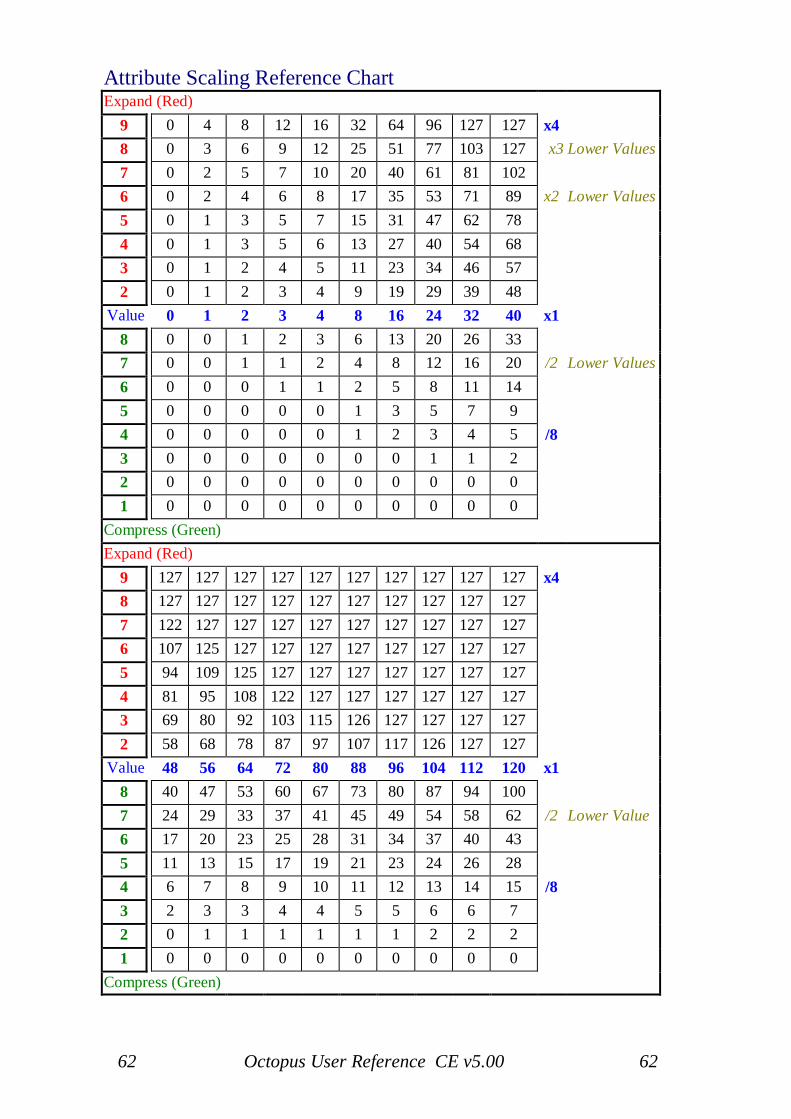
62 Octopus User Reference CE v5.00 62
Attribute Scaling Reference ChartExpand (Red)
9 0 4 8 12 16 32 64 96 127 127 x48 0 3 6 9 12 25 51 77 103 127 x3 Lower Values7 0 2 5 7 10 20 40 61 81 1026 0 2 4 6 8 17 35 53 71 89 x2 Lower Values5 0 1 3 5 7 15 31 47 62 784 0 1 3 5 6 13 27 40 54 683 0 1 2 4 5 11 23 34 46 572 0 1 2 3 4 9 19 29 39 48
Value 0 1 2 3 4 8 16 24 32 40 x18 0 0 1 2 3 6 13 20 26 337 0 0 1 1 2 4 8 12 16 20 /2 Lower Values6 0 0 0 1 1 2 5 8 11 145 0 0 0 0 0 1 3 5 7 94 0 0 0 0 0 1 2 3 4 5 /83 0 0 0 0 0 0 0 1 1 22 0 0 0 0 0 0 0 0 0 01 0 0 0 0 0 0 0 0 0 0
Compress (Green)Expand (Red)
9 127 127 127 127 127 127 127 127 127 127 x48 127 127 127 127 127 127 127 127 127 1277 122 127 127 127 127 127 127 127 127 1276 107 125 127 127 127 127 127 127 127 1275 94 109 125 127 127 127 127 127 127 1274 81 95 108 122 127 127 127 127 127 1273 69 80 92 103 115 126 127 127 127 1272 58 68 78 87 97 107 117 126 127 127
Value 48 56 64 72 80 88 96 104 112 120 x18 40 47 53 60 67 73 80 87 94 1007 24 29 33 37 41 45 49 54 58 62 /2 Lower Value6 17 20 23 25 28 31 34 37 40 435 11 13 15 17 19 21 23 24 26 284 6 7 8 9 10 11 12 13 14 15 /83 2 3 3 4 4 5 5 6 6 72 0 1 1 1 1 1 1 2 2 21 0 0 0 0 0 0 0 0 0 0
Compress (Green)
63 Octopus User Reference CE v5.00 63
Track direction editing
As we have seen in earlier sections, each Octopus track may be assigned itsown running direction. This is exciting, but neither new, nor spectacular.What may catch your attention though, is that on the Octopus you can notonly specify what direction a track should play, but in most cases also editthat direction to your particular gusto.Directions 1-5 are read-only, while directions 6-16 are user editable.To see how all this works, let's take a quick step back and realize a coupleof things. Then you will see how the pieces fall into place.
A general view on directionsTo begin, have a track run at the default forward direction (Direction 1). Letit run for a few cycles in the forward direction, then stop.Think about what you just saw: the forward direction is really "the sequenceof chaser light positions in each of 16 slices of time it takes to play all stepsin a track". Makes sense? Realizing this is the key to understanding howediting directions works.
Triggers and slicesEach of the 16 slices needed to play a track from end to end (no skips fornow) specifies its own chaser light position trigger. For the forwarddirection, in slice 1 we have a trigger for chaser light position 1, in slice 2 atrigger for position 2, etc.In simple terms, when a track is played, the chaser light will be movedaccording to the triggers specified by the slices that make up that particulardirection. For example, the reverse direction has the trigger sequence [16,15, 14... 1] assigned to its slices.
Full and empty slicesTo take it one level further, a slice is not restricted to holding only onetrigger, but may hold up to nine triggers. These nine triggers will be playedin sequence every time the respective slice is being played. This impliesthat a slice may take as long as nine times to play completely, because itfires up to nine triggers.So what do we get from empty slices, i.e. where no trigger is specified?Well, every time Octopus gets an empty slice, it will pick a trigger for youat random*, and play it normally.
64 Octopus User Reference CE v5.00 64
Certainty_nextThe sequence of slices is per default set to be a solid 1, 2, 3 ...16. But youcan change that. Each slice has an associated „certainty_next" parameter,which is expressed as a percentage.A setting of 100% means that the next slice will be the one followingnaturally (i.e. slice 3 will be followed by slice 4, etc.).A setting of 0% will specify that the next slice will be the naturally previousone (i.e. slice 3 will be followed by slice 2).Any value in-between will produce the obvious: for example, a setting of50% will mean that there is a 50/50 chance by which the next or theprevious slice will be called - and then its triggers played.Note that the certainty_next parameter applies to the switch between slices,but does not apply to the trigger set and sequence inside a particular slice.For example: Let's assume slice 4 has a certainty_next of 50% and a triggerset of 2, 5, and 8. Once started, the slice will first fire up its triggers (2, 5, 8)and then decide which slice to call next - slice 3 (previous one) or slice 5(next one).
Playing direction mapsSo now, how do you work with all of this? The answer is "Direction Maps".From Track Mode (of any track), select for that track the direction youwould like to program.Make sure to choose a direction between 6 and 16, since directions 1-5 areread-only and cannot be modified.After choosing the direction, double-click on the DIR attribute button toenter the direction map. In this view, you will see in row 0 a orange light,reminding you of the index of the position you are just about to edit.Press some of the keys in row 0 and you will see a green blinking lightfollowing your presses - the green blinking light is showing you the indexof the slice that you are just editing. When the blinking green and theorange light overlap, you will get a blinking orange light.
65 Octopus User Reference CE v5.00 65
Editing trigger setsThe area above row 0 (i.e. rows 1-9), will show none, one, or more redlights, which specify the triggers contained in the selected slice.You may select triggers at will by simply toggling them in the Matrix, butthere can be only one per row: the trigger sequence is naturally given by therows you select them in. Therefore, a row will only hold one trigger.Rows holding no trigger will simply be ignored at runtime. But remember,if all rows are empty, you will get a random* trigger to play in that slicebefore the next slice is called.
Editing Certainty_nextWhile editing, you may jump between trigger sets using the key of row 0 asyou like. Last thing to mention is the certainty_next probability.This is simply the number shown in the numeric field of the circle, in thetop left quadrant. The number is edited as expected, using the top rightrotary encoder, in addition to the buttons in the numeric quadrant.Here, some key combinations may be of interest: double clicking 5 willproduce a 50, clicking (simple) 100 will produce 100, and double clicking100 will produce a 0.For the rest, it is left as an exercise to the reader to look at how the fivedefault directions are programmed, in order to get the final clarification orconfirmation on having understood how the Octopus direction modelworks.Please also refer to the dedicated tutorial in the back section of this manualor available as a separate document on our web site.
RemarksThe direction map is no different to the other maps we have seen so far:press ESC at any time to return to the page mode, but be aware that anychange you make to the direction will be permanent, like any other changeon the Octopus. However, unlike with regular MIDI data, there is no"PLAY" capability for the directions. You may however use CLR to restorethe forward direction in slots 6-16. In fact, remember that directions 1-5 areread-only and not editable.Finally, when you need an inspiration boost, go into a direction mapand start using RND. That one may get you going.
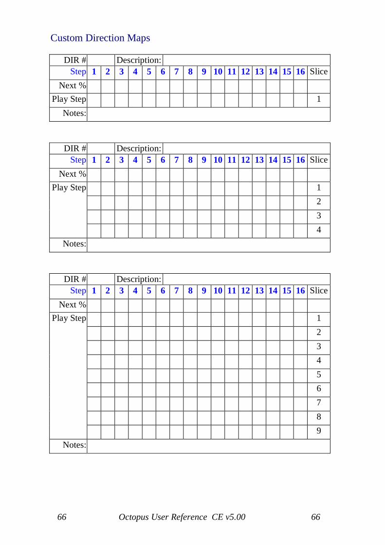
66 Octopus User Reference CE v5.00 66
Custom Direction Maps
DIR # Description:Step 1 2 3 4 5 6 7 8 9 10 11 12 13 14 15 16 Slice
Next %Play Step 1
Notes:
DIR # Description:Step 1 2 3 4 5 6 7 8 9 10 11 12 13 14 15 16 Slice
Next %123
Play Step
4Notes:
DIR # Description:Step 1 2 3 4 5 6 7 8 9 10 11 12 13 14 15 16 Slice
Next %12345678
Play Step
9Notes:
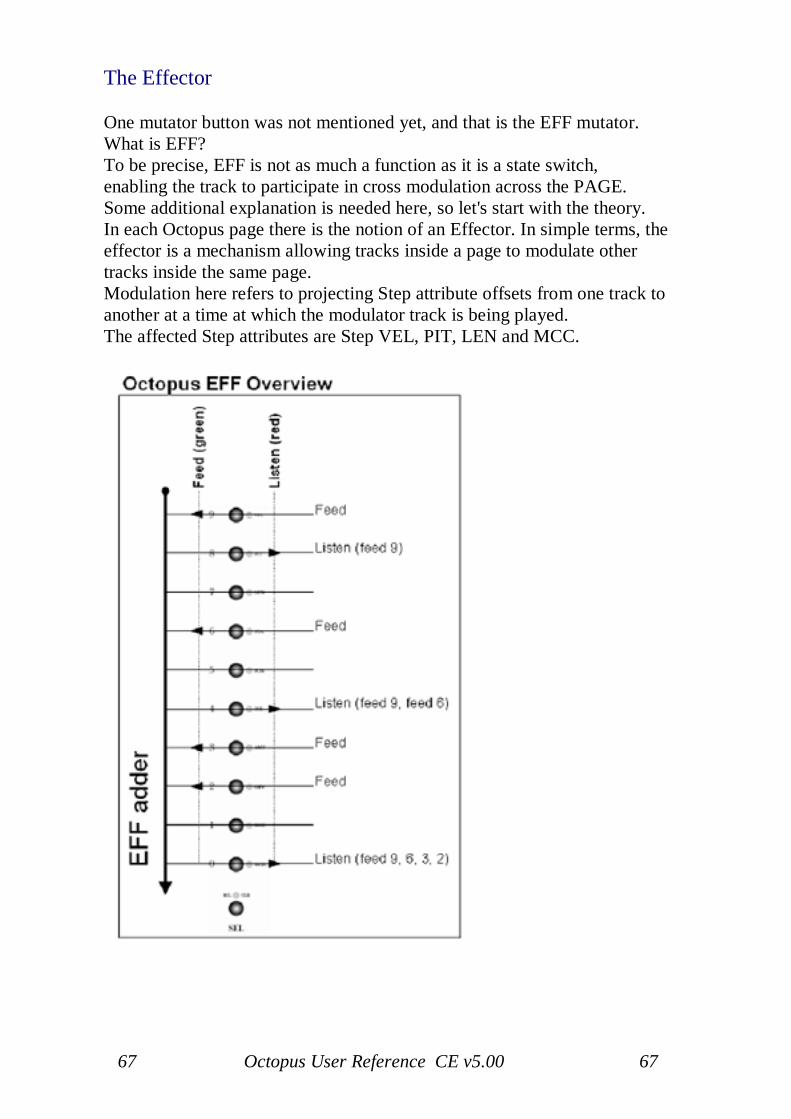
67 Octopus User Reference CE v5.00 67
The Effector
One mutator button was not mentioned yet, and that is the EFF mutator.What is EFF?To be precise, EFF is not as much a function as it is a state switch,enabling the track to participate in cross modulation across the PAGE.Some additional explanation is needed here, so let's start with the theory.In each Octopus page there is the notion of an Effector. In simple terms, theeffector is a mechanism allowing tracks inside a page to modulate othertracks inside the same page.Modulation here refers to projecting Step attribute offsets from one track toanother at a time at which the modulator track is being played.The affected Step attributes are Step VEL, PIT, LEN and MCC.
68 Octopus User Reference CE v5.00 68
The EFF mechanism
The modulation is always happening "top-down", i.e. upper tracks maymodulate lower tracks, but not vice-versa.Here "upper" and "lower" refers to the respective track index. For example,track 9 may modulate all other tracks but track 0 cannot modulate any othertrack.
Feeders, Listeners and Listening FeedersModulator tracks are called "feeders" and modulated tracks "listeners", for abetter distinction of terms.Because the effect of the feeder tracks is additive down the track indexes,you may picture the feeder tracks as feeding the effector and listener trackslistening to whatever is in the effector at their particular index slot.A track may also be both a listeners and a feeder, which we call a listeningfeeder. This means that if that track itself is playing notes, then theattributes of those notes are modulated, while the resulting values willmodulate the corresponding listeners below it.
Effector dry-runIn the example below, Track 9 is feeding its Step offsets for VEL, PIT andLEN into the effector.
This means that all listeners in the page may be modulated by those offsets.In this example we have set tracks 8, 4 and 0 as listeners, and therefore tobe modulated by track 9's offsets.Assuming that Track 9 is currently at a Step whose PIT offset is +3, andassuming no other feeders exist, the notes played in the tracks 8, 4, and 0will be played 3 semitones higher than defined in those tracks for thecurrent position.But: track 6 is also a feeder, and modulates all listeners below it,i.e. Tracks 4 and 0. Assuming that the current Step in track 6 has a PIToffset of -1, listener tracks below will see a total PIT modulation effect of+3 -1 = +2.Similarly, Tracks 3 and 2 are set as further feeders, which means that thelast listener, Track 0, is being modulated by four feeders: Tracks 9, 6, 3, and2.Assuming Tracks 3 and 2 each have a Step PIT offset of -2, this meansthat the net PIT offset for row 0 is: +3 -1 -2 -2 = -2.
69 Octopus User Reference CE v5.00 69
RemarksThe values fed into the effector are really the deltas between the actual stepoffset for a given attribute and the default value of that attribute. In theabove example the default step offset was always 0.The first remark here is that the offsets fed into the effector may obviouslybe both positive and negative.The second remark to make is that the attribute values fed into the effectorby both feeders and listening feeders will be influenced by the factor set forthat particular track.When using step events to scale both the feeder track and the listener track,the feeder offsets are only applied to the listener after the listener has itselfbeen scaled.
Using EFF with eventsThe effector may be used in conjunction with using events to modulate thetrack attribute map factors.We will not elaborate further on the possible results, and leave it as anexercise to the reader, but this does open quite new ways of crossmodulation among the page tracks.
Playing the Effector
FeedersOn to the operation of the Effector. Just as a reminder, the Effector is atrack specific attribute and as such it must be toggled either in TRACKmode, or from PAGE mode by grabbing the track and pressing the TGLbutton in the MUT column.Setting a track to be a feeder is done by pressing its EFF mutator andtoggling its EFF state to green.It is important to note that a Feeder track need not contain any active Steps,i.e. need not play any notes in order to act as a modulator for other tracks.
ListenersIn order to set a track to be a listener, click its EFF mutator to toggle it red.Pressing a red EFF button will toggle it orange, making the track a listeningfeeder.
70 Octopus User Reference CE v5.00 70
Listening feedersA listening feeder gets modulated first and then amplifies the incomingmodulation with its own effector feed.
Pressing the EFF button will toggle it off, with the track not participating inEffector modulation.
PlayingFor the Effector to work, it is merely the offsets of its Steps that count, andit is completely irrelevant whether those steps are generating MIDI notes ornot.However, if an effector feeder does contain active steps, these will beplayed regularly, as they would independent of the effector.
MutingIf a feeder track is muted, it will not have any effect on listener tracks.Toggling feeder tracks is a quick way to introduce changes to a track andthen to go back to the original sound.
The Effector at workDesignate a feeder track. Set step 1 in the feeder track and pitch it up ordown.Now select a track with an index smaller than the effector feeder (this isessential) and build a pattern into it involving lots (if not all) steps.Make sure that step 1 is set as part of the pattern and play the pattern.Now make this track listen to the effector by toggling its EFF mutator to redby double clicking on the EFF button.You should now hear that the step in column 1 of the listening track is nowplayed differently, with the PIT offset from the Feeder track applied to it.The popular thing to do now is to start changing the track lengths for feederand listener to get long-running modulation results.
Note: The Feeder steps will only pass a MCC value if the Feeder Track isset to an MCC (the step MCC is passed - not the track MCC), therefore, toavoid unexpected effects, set the Feeder track to a different MCH from thelistener(s).
If a Feeder step LEN attribute is set to legato then the listener track(s) willoutput their step LEN attribute at the minimum step length (not legato).
71 Octopus User Reference CE v5.00 71
4. Page Mode
Page Mode Index
Page Mode: Page Mode:Attribute MIX maps 79 Mix Map Setups 83Bank View 86 Mix Map Targets 80Clear 85 Mix Maps 79Copy 85 Musical Scales 76EDIT Perform state 73 Page POSITION in GRID 85EDIT Steps state 72 Paste 85Editor ATR state 74 Play (Snapshot) 87Editor MCC state 75 Playing Controller Maps 81Exempting Page from FTS 78 Random (RND) 85Force to Scale 76 Remix (RMX) 85Force to Scale - Quick Guide 78 Scale Cadence 77Locking the Page Scale 77 Solo (SOL) 85Midi Control Map Values 81 Switching Pages 85Mix Map Attr - Quick Assign 79 Toggle (TGL) 84Mix Map - Clear 79 Viewing the Mix Map 79
EDIT state
Octopus provides a quick way of previewing steps, in the sense that you canimmediately hear what they contain, and how they would play under thechase-light.This is particularly interesting of course when you are tweaking somethingto sound just right.
By default, in PAGE mode the EDIT LED button lights steady green. Clickon it once to toggle it to blinking orange.
When the EDIT LED is lit steady green, everything behaves as you know it:the step buttons toggle the step states. When turned to blinking orange youare in the EDIT state.To return to the default state (steady green), press the EDIT buttontwice (again - twice, and not double-click!).
72 Octopus User Reference CE v5.00 72
Editing Steps (Flashing Orange - Edit Realtime)
First make sure the EDIT LED is flashing orange.Now press some buttons in the matrix. You will notice that no steps will beset (as we have done it before), but that the MIDI data of the steps is playedout of the MIDI port as it is.Grab a step and now tweak its attributes, for example pitch, to take the mostobvious one: you will hear that with every click of the encoder the steps isre-triggered and played such that you can hear the change in real time.The step velocity is shown and editable in the numeric quadrant of the outercircle, the pitch in the inner circle.
In this mode the step length may also be adjusted in the matrix, by holdingthe step to be adjusted and pressing another button at a distance to denotethe length in 1/16th intervals or alternatively by holding the step to beadjusted and clicking a button in the same column(above or below) to setthe held step to a LEN of 192/192.
Editing TracksPressing the track selectors in preview mode will produce a result similar tothe steps buttons.The note played will basically reveal the tracks velocity and pitch settings,producing a result equivalent to having a non-modified step playing in thattrack.
73 Octopus User Reference CE v5.00 73
EDIT PERFORM state (Flashing Green - Berlin)
Use this mode for tweaking Steps.
An alternative and quite rewarding mode of working with a step sequence(depending on your style and preference) is that of tweaking a set sequenceof steps in realtime, while the sequence keeps playing.You can also do this to some degree without a special mode, but EDITPERFORM takes this to perfection.
EDIT PERFORM is actually similar to the EDIT state, with the exceptionthat no MIDI data is transmitted when you operate on the matrix. This isparticularly interesting for the Berlin School type of performances.
By default, in PAGE mode the EDIT LED button lights green. Click on itonce to toggle it to blinking orange, and once more to make it blink green.
Again, when the EDIT LED lights steady green, everything behaves as youknow it: the step buttons toggle the step states. When EDIT blinks orangeyou are in EDIT mode, and when EDIT blinks green you are in EDITPERFORM mode.
In this mode the step length may also be adjusted in the matrix, by holdingthe step to be adjusted and pressing another button at a distance to denotethe length in 1/16th intervals or alternatively by holding the step to beadjusted and clicking a button in the same column(above or below) to setthe held step to a LEN of 192/192.
74 Octopus User Reference CE v5.00 74
Editor ATR state
In Page mode, an ATR may be temporarily assigned to the EDIT knobgroup.
EngageThis is done by holding the selector of the respective attribute to select theattribute, and at the same time pressing the EDIT master button to make theactual assignment. The indicator for the Knob group will light orange,indicating activity.In this mode the EDIT knobs will behave just like another group of MIXknobs for the just selected attribute.
DisengagePressing the EDIT master button once will cancel the assignment and returnto the legacy mode of operation.
75 Octopus User Reference CE v5.00 75
Editor MCC state
The EDIT button has one more state - that is the MCC send state.This is used to make the editor knobs send MCC data.
Sending MCC dataThe MCC amounts sent will be on the MIDI channel and controller chosenin their corresponding tracks. See section on Track Attributes if you don'tremember the details for setting up Track MIDI CCs.
EngageTo activate the MCC state, double-click on the EDIT button turning it red.
DisengageTo deactivate the MCC state, just press the EDIT button once.
76 Octopus User Reference CE v5.00 76
Musical scales
Each page can be associated with a particular musical scale. Once thatassociation is done and a scale is active, all page notes are forced to play inthe chosen scale.
Force to scaleForce to scale for a page is enabled by going to PAGE mode and simplypressing the green lit SCALE SEL button. Coming from the default state,you will see its LED turn red and all scale notes light up, with the exceptionof upper C.Conversely, force to scale is disabled by pressing the red SCALE SELbutton, which indicates that force to scale is engaged.So, in general, the red LED of SCALE SEL is indicating that the pagepitches are forced into the scale, a green LED indicates that the page isplaying the pitches as they are.The lower C LED is also lit orange. What you see here is that all notes areselected in the scale, and that C is the base tone of this scale. Let's nowmodify the scale to get more interesting effects:
Composing scalesWhile having force to scale active as described above, press the Selectbutton (in the outer circle, button XIV) and it should blink orange, while theChr. scale LED (XX) is lit orange.This picture is telling us that the chromatic C scale is currently active, butthat we may select any notes in our current scale.The Select button you have just pressed is used to let you select the notesthat you would like to add to your scale. Now press any of the note keys inthe scale circle to toggle the corresponding notes into and out of the scale,putting together any scale you like.Once you are done selecting the scale notes, you may press SCALE MODagain, and now you can modify (again) the base pitch of the scale you havejust selected.Another way to select a scale is to press any of the scale buttons in the outercircle, to get the scale structure associated with their label, always on thebase tone indicated by the orange LED.
77 Octopus User Reference CE v5.00 77
Changing the scale baseIn order to change the base tone, press the SCALE MOD button to enter thescale modulation mode. Here you may select any of the current scales tonesas the new scale base.As you change the scale base you will see the scale signature carry over tothe new base as well.
Scale cadence modeAnother way of operating the Scale data is to combine it with the CADfunctionality. What this means is that any changes done to the scale willtranslate into immediate mappings onto the track pitches in the page athand.To activate the SCALE CAD, please activate force-to-scale if not alreadyactive, and then press CAD (so it blinks red indicating operation).In order to make the effect clearly visible (on top of audible) you may alsowant to select the MIX mode for the track pitches (double click on the ATRkey in the MIX TARGET field, then select PIT).Now modify the scale as described and you should see the changes to thetrack pitches as they materialize in the matrix.
Locking the page scaleYou may want to have your page notes forced to the selected scale, but notsee the details behind that and also prevent any unintended changes to thescale, essentially locking it.In that case, while in SCALE mode, press ESC to leave the page forced tothe scale, but to exit the SCALE mode. You will notice that the SCALESEL LED will blink orange, indicating that the page is forced to scale. Togo back into the scale edit mode, simply press the orange blinking SCALESEL LED.
The grid scaleThe GRID may be assigned a scale, in the same manner that a scale isassigned to a page, except the GRID scale will act globally.To operate the GRID scale, switch first to GRID mode. Use the SCALESEL button and proceed as already described in the section describing thePAGE Scale operation.
78 Octopus User Reference CE v5.00 78
Exempting pages from the grid scaleNote that by definition, the GRID scale is overruled by any other scalesactive in particular pages.Therefore, an easy way to exempt a page from the grid scale is to force thatpage to a chromatic scale. This may be particularly useful in the case ofpercussive material for example.
Force to Scale - Quick Guide
Scale SEL Lit Green - No Force to Scale.Scale SEL Lit Red (or flashing Orange) - Force to Scale Active.
Press Scale SEL to activate Force to Scale, LED turns Red then either selectscale with Outer Circle button (Maj, Min etc) or press Select (XIV) buttonand choose notes.
The Scale base note is shown in Orange, to change the base note press ScaleMOD button then choose a new base note - press Select (XIV) button againto go back to choosing scale notes.
Pressing Scale CAD will change Track default notes to the defined scale(not a good idea as this will change to default note octave also).
Pressing ESC will leave Force to Scale active and Scale SEL LED willflash Orange (notes of scale will no longer show).
79 Octopus User Reference CE v5.00 79
The Mixer block
Viewing the MIX mapDouble click the ATR button. This brings you to the MIX TARGETassignment, where a parameter can be assigned to the MIX encoder group.The Mix Target LEDs light all up, indicating the selected target in blinkingorange. Also, the matrix is showing in every row the value respective to thecorresponding track for the chosen attribute.This type of display is called a MIX map, showing the behaviour of thetracks with respect to a particular attribute, which can be adjusted using theMIX encoder block.As a matter of fact, clicking on any of the MIX target buttons will open aMIX map view, with the respective values showing, and ready to edit. Wewill describe this in the next sections in more detail.
Mix attribute quick assignA very quick way to assign an attribute to the MIXER BLOCK is to selectthe attribute (i.e. to select GRV, press and hold the selector of row 2), whilepressing the MIX button. Or vice versa - hold the MIX button pressed andpress the track selector corresponding to the wanted attribute.By pressing the MIX button you will notice that the selected attribute hasbeen changed - the current selected mix attribute is blinking orange in theselector column.
Working with Mix maps
While viewing MIX maps, you can work with a particular track attributevalue directly, for all tracks at once. You may tweak the value of any onetrack, or apply some functions to all tracks in the page.
ClearClear the MIX map using the CLR button - this will reset the MIX map todefault values for each track in the page, all at once.
RandomizeYou may randomize the displayed values using the RND button. This willassign random values to all tracks at once - for the selected attribute ofcourse.
Align
80 Octopus User Reference CE v5.00 80
Using the ALN function you may re-order the tracks in the page, sortingthem in the page by the values of the selected MIX MAP attribute. Thesorting will be done such that the track with the highest value will be placedon the top row. Try it out!
Copy / PasteFinally, if you have composed a page whose MIX map you would like toreplicate, you may use the CPY / PST functionality to replicate thatattribute assignment across the tracks.For example, assuming you have a page whose pitch structure creates acertain mood or harmony; you can apply the same mood to an entirelyunrelated page or pattern, by simply copying the PIT map from one page tothe other.
Mix map targets
Going back to editing, there are three classes of targets: attributes (ATR),preset MIDI CC's (any of VOL, PAN, MOD, EXP), and MIDI ControlMaps (MAP 0-5). Some explaining is due here.
AttributesIf the ATR type is selected by a double click, the SEL buttons will light upgreen, indicating that any of them may be selected. The already selectedattribute will blink orange.The matrix will show the value relevant for the respective rows.All rotary knobs act upon the same attribute on their respective track. Forexample if PIT (pitch) is selected, every rotary will change the pitch of itsassigned row.
Preset MIDI CC'sThe MIDI CC's behave the same as the ATR targets. The CC's used are:VOL (7), PAN (10), MOD (1), EXP (11).
MIDI Control MapsUsing a MIDI Controller Map, any MIX knob can be assigned an individualCC on a chosen MIDI channel.As an example, double click on MAP 0 to select MIDI Controller Map 0.You will notice that the AMT button will blink orange indicated that AMT
81 Octopus User Reference CE v5.00 81
is selected. The matrix shows the per-track AMT values, which is really theCC amount set on each of the tracks.Press the MCC button. Here the Matrix shows the actual Midi ContinuousController assigned to each of the tracks.You can modify the CC for every individual track using the MIX knobs.Remember that four green LEDs in positions 13, 14, 15, and 16 indicatethat no CC has been assigned.Now press the MCH button. This view allows you to assign the MIDIchannel on which the CC signal is sent.Note that this is not the MIDI channel of the Track - the track's MIDIchannel is an entirely independent parameter.Finally, the settings that you have just made are stored as a MIDI ControllerMap. There is a total of 6 MIDI Controller Maps, and they are global. Thisis useful because you can have MIDI map operate beyond the context of apage, as they fulfil a global function.
Playing MIDI Controller MapsMIDI Controller Maps may be edited and operated directly from both theGRID and the PAGE level.Select one of the MIDI Controller Maps, 0-5. You will see that the LED forthe corresponding map is lit orange to show that it is currently active.
TimeoutThe MIXER block may be used at any time during PAGE mode operation.In order to make the effects visible, once you operate any of the MIXencoders in PAGE mode you will see its value displayed briefly in thecorresponding matrix row.The value will disappear shortly after you have performed the last click, toclear the view for the regular contents of the track.
Midi Control Map ValuesThe AMT values are effectively the 'start point', turning the encoder willsend out the value + or - the Map AMT 'start-point' value.
Note: Once a Midi Control Map has been changed during a performancethe only way to reset to the stored map values is via a 'hard reset'.
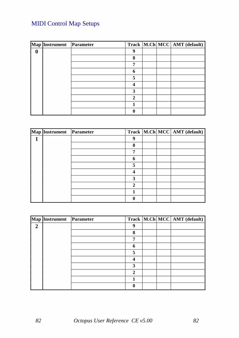
82 Octopus User Reference CE v5.00 82
MIDI Control Map Setups
Map Instrument Parameter Track M.Ch MCC AMT (default)0 9
876543210
Map Instrument Parameter Track M.Ch MCC AMT (default)1 9
876543210
Map Instrument Parameter Track M.Ch MCC AMT (default)2 9
876543210
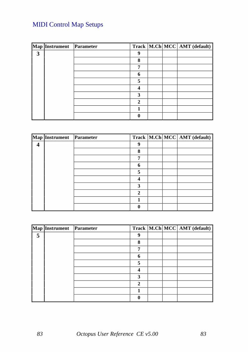
83 Octopus User Reference CE v5.00 83
MIDI Control Map Setups
Map Instrument Parameter Track M.Ch MCC AMT (default)3 9
876543210
Map Instrument Parameter Track M.Ch MCC AMT (default)4 9
876543210
Map Instrument Parameter Track M.Ch MCC AMT (default)5 9
876543210
84 Octopus User Reference CE v5.00 84
Page Operations
When in PAGE mode, holding the PAGE key pressed will make somemutator functions available for the page itself - the expected results shouldbe quite obvious. Applying them is a matter of pressing the appropriatemutator button.
TGLPressing TGL will toggle the page play status in the grid.
SOLPage will be solo-ed and un-solo-ed. When solo-ed, the Page LED in thecircle will blink green as opposed to orange
CLRUsing CLR on a page will reset the page to the default page values,including resetting the tracks to their forward moving direction.
RNDThis will fill the page with random step patterns on all tracks. Note that thetrack attributes are not affected, just the step patterns.
RMXAll tracks in the page will be applied the RMX function. See track mode fordetails.
CPYPage can be copied to the copy buffer. The copy operation will include thechain configuration local to the page at the time of copy.
PSTCopy buffer will be pasted into the present page position.
Page POSITION in GRIDAnother function available is jumping to another page of the grid. As youpress the PAGE key you will notice a orange LED blink in the Matrix. Thisindicates the position of the current page in the grid.

85 Octopus User Reference CE v5.00 85
Switching pagesHolding PAGE pressed and pressing a matrix key other than the oneblinking and in any row other than row 0 will take you directly to the pageassociated with that key in the grid.This is especially useful when you are working on musical structuresspanning several pages.Holding PAGE pressed, the current matrix Page will flash orange, whenpressing a new matrix Page the newly selected page will flash orange andthe previous Page will be green (as it is still the 'current' page playing) -now, whilst still holding the Page button press TGL and (at the end of theTrack the newly selected Page will turn green and the previously selectedPage will turn Red
86 Octopus User Reference CE v5.00 86
Bank view
When in PAGE mode, by default you see a green lit Select LED in the topright quadrant of the circle, along with the orange Tempo LED.
They indicate the two available modes for the main knob and the numericfield: one of them (default one) is to show master tempo in the numericfiled of the circle, the other one is what we call the bank view.
A bank is the set of 16 pages that live on the same Grid row, and which aremutually exclusive at playtime, meaning that only one page may play perbank, at any time.
Entering bank viewPressing Select will allow you to see in the numeric field the banks that arecurrently playing (i.e. contain a playing page) as green lit buttons.The orange blinking one is the bank currently in your matrix editor.Note that this says nothing about which column in the bank is currentlyplaying, as a bank only says something about the Grid row that a pageresides on.Pressing any of the green lit buttons will take you directly to the currentlyplaying page in that bank.Turning the main knob will incrementally take you through the playingpages.This is just a way of jumping between the (up to 9) concurrent pagesplaying.
Exiting bank viewPress the Tempo button to return to the standard Tempo display.
87 Octopus User Reference CE v5.00 87
Play mode
The PLAY mode provides the capability to try new things in a page, in anon-destructive manner.Activating the PLAY mode is equivalent to taking a snapshot of thecurrently playing page in a bank for later recall, in case the results of yourediting do not live up to your expectations. Notably, the play modesnapshots include track mute patterns of the respective pages.Also note that engaging the PLAY mode may be done from both page modeand from grid mode.
Engaging play modeTo activate the PLAY mode press the green PLAY button in the MODEblock and you should see it blink orange.Also you will notice that the Program button will be lit red.
Now make all the changes and editing that you need to make to your pageuntil you reach a point of satisfaction, or possibly slight regret.Use EDIT state PREFORM (flashing green)
Make changes permanentTo keep the page, simply press Program to make the changes permanent.
Discard changesTo discard the changes, press PLAY again, exiting the PLAY mode andrecalling the state of the page from just before you started.Note that upon stopping the sequencer you will also lose any changes madeduring PLAY mode.

88 Octopus User Reference CE v5.00 88
89 Octopus User Reference CE v5.00 89
5. Grid Mode
Grid Mode Index:
Grid Mode: Grid Mode:Bank mute toggles 93 Grid-Track mode 91Bypassing memory reload 98 Interface locking 98Chase-light align 98 Musical Scale 97Chase-light Page Cluster Follow 95 Page Length (LEN) 94Cluster Activation 93 Page Repeat (STA) 94Exempting Pages from Grid FTS 97 Page Sets 96Force to scale - Quick Guide 97 Page Transposition (PIT) 95Grid Clear 89 Page Velocity factor (VEL) 95Grid Edit mode 90 Start-up defaults 89Grid Live mode 90 Where are you from? 98
Operations
Grid Clear - Resetting to start-up defaultsPlease note that doing this will erase any changes you have made andpossibly want to keep, so use this with extreme caution!Press and hold the GRID mode button, while pressing the Clear button.Again, this only clears the RAM (volatile) memory contents and leaves thecontent of the FLASH (non-volatile) memory untouched.
Other OperationsIn Grid Edit modes to following operations are available, Page Clear, PageSolo, Page Copy, Page Paste & Page Remix. Simply hold the relevant Pagein the Matrix and click the required mutator.
90 Octopus User Reference CE v5.00 90
Grid Modes
Grid EDIT modeFurthermore, you should take quick notice of the EDIT LED. It should lightflashing orange to indicate that we are currently operating in Grid EDITmode.
Grid LIVE modeThe Grid live mode is more suited in the cases where you are playing yourmaterial live, hence the name. In Grid live mode the matrix buttons will actas toggles for the respective pages. This provides more immediate andintuitive handling of material in live situations.Switching to Grid live mode is quite easy if the EDIT LED is flashingorange (default state) press it once to turn it green.
Operating in Grid live mode is easily explained. In principle, the pagebuttons now act as page toggles, much similar to the way things work inpage mode, where buttons act as step toggles.For Example: Pressing a page button that is red (page is not playing), willturn that page on. Pressing the button of a playing page (green) will turnthat page off.There are two page switch modes, "on the beat" and "immediate". To togglebetween them simply press the Tempo button. "On the beat" is denoted by ared master clock indicator, "immediate" by a green one.
91 Octopus User Reference CE v5.00 91
Grid-Track mode
The GRID-TRACK mode may be imagined as a sub-mode of the GRIDMode. The GRID-TRACK mode provides most of the GRID functionalitydescribed above, al lowing a different vie w on your MIDI data.Here, matrix buttons represent tracks (as opposed to pages) and have thefunctionality of track selectors, as described for the PAGE Mode.We may refer to them as virtual track selectors.
Entering the Grid-Track modeTo enter the GRID-TRACK mode, enter the GRID mode first (by pressingGRID) and then press the green-lit TRACK button.The TRACK button will blink orange, and the GRID button will stay lit inorange. This indicates that you are in the GRID-TRACK mode.
Virtual track selectorsThe Matrix will slightly change its contents and some explanation isnecessary to what it now conveys.For each page playing in the GRID, you will see a lit bar of 10 LEDs, fromposition 4 to position 13, leaving three blank columns of buttons on eachside.Each lit button acts as virtual track selectors and the LEDs indicate thetoggle state of the corresponding track.
Hands-onAs an example, let's assume there is only one page playing in the GRID inbank 1 of the grid and no tracks are muted in that page. You should see abar of 10 green LEDs in row 1, positioned in the centre of the row (3 unlitLED's to each side of the 10-LED bar).
Working with tracksMoving from here is easy: press and hold any of the virtual track selectorsand you will see that two mutator functions become available:TGL and SOL.Also, the EDIT block indicator blinks orange, as you may use the encodersto modify the track selected via the virtual selectors.When exactly one track is selected in GRID-TRACK mode, the pitch ofthat track becomes visible and editable in the inner circle, just as we haveseen it in PAGE mode.
92 Octopus User Reference CE v5.00 92
Quick track toggleSometimes all you want to do in GRID-TRACK mode is to toggle tracks onthe fly. There is a quick way to do that by holding any button that belongsto columns 1-3 or 14-16 while pressing a virtual track selector. The virtualtrack selector now directly toggles the mute status of the respective track.
Zooming into tracksYou may do much lower-level editing of tracks, simply by double- clickinga virtual selector to enter TRACK mode for that track, i.e. zooming into thattrack. And you know your way around there already.To return from TRACK mode to GRID-TRACK mode simply press theGRID and TRACK mode buttons at the same time - this proved to workwell.
Grid-Track live modeThe GRID-TRACK live mode is much similar to the live mode in Gridmode. It is activated by pressing the EDIT button LED such that it is litgreen.When in live mode, the matrix buttons will act as toggles for the respectivetracks. This provides more immediate and intuitive handling of material inlive situations.
Leaving Grid-Track modeIn order to exit the GRID-TRACK mode, press either the GRID or theTRACK button. Both of them will simply take you back to GRID mode.
93 Octopus User Reference CE v5.00 93
Page Clusters
Building clustersIn order to play two or more pages consecutively they have to be situatednext to each other in the GRID. You can achieve this easily by using CPY /PST / CLR mutator functions in order to create what we shall call pageclusters.A page cluster is therefore a group of two or more adjacent pagessurrounded by either empty pages or grid margins.
Cluster activationCreate a page cluster consisting of three pages in a row of your choice.Once the cluster is built, make sure the sequencer is playing and toggle oneof the pages in the cluster to green (i.e. make it play).The page will keep on playing.Activate cluster play for the row in which the cluster exists by pressing theSEL button of that row once - toggling it from red to green.When green, you will notice that once the currently playing page is finishedplaying the next page in the cluster starts to play and so forth.
Cluster Page HoldWith an active Page Cluster any page can be made a 'hold page', clusterplay will not advance beyond the 'hold page' until the 'hold' is turned off -see Page Repeats (STA). When a Cluster Hold Page is playing it will beshown in the Grid as flashing green.
Bank mute togglesIn GRID mode, the buttons in the MUT column act as bank mute toggles.Pages in muted banks will continue playing in sync with all active ones, buttheir output will not be sent out to MIDI. This provides more immediateand intuitive handling of material in live situations.
94 Octopus User Reference CE v5.00 94
Page play parameters
Page repeats (STA)Page clustering can become even more fun, as you can set the number ofrepetitions individually for each page. For example, page A can play 4times, page B 2 times and page C 1 time. The number of repetitions can beany value between 0 and 16, where 1 is the default value.In order to set the repetition value for a page, simply keep it pressed andselect the number of repetitions in row 0 - for any number between 1 and16. You may press on a page's key and you will see the repetitions valuealong with the currently left number of repetitions for play (double-click toset value 0). Another way of modifying a page's number of repeats is tohold the page in the grid, while turning the STA knob in the edit block.Note: Page STA value of 0 is a special value that signifies a Cluster HoldPage, i.e. Cluster Page Play will not advance to the next Page until the'held' page STA is changed to a value other than 0.
Page length (LEN)When pages play, they are set per default to play 16 step positions, afterwhich they play another 16 steps and so on. These rather natural sixteen16th positions make up what we call the length of the page, i.e. how manypositions until the track "wraps around".However this value may be changed to a number higher or lower than thenatural 16. For example, assuming length 12 for a modified page playingalong with a reference page with length 16, the modified page will play itsfirst 12 positions, after which it will play once more its first 4 positions.After that it will start over from position 1 and so on.Let's see briefly how this may be used: As we have seen, clustering pages isa way to create structures spanning more than one page. If you have workedwith pages that contain tracks of different lengths and had these be part ofclusters, you may have wondered what determines the moment of switchingfrom one page to the next.To set the page length of a page, make sure you are in GRID mode, andfrom there press and hold the button of the page whose length you want toread or modify. When pressing the page button, notice that the SEL LED inrow 0 will be lit and can be pressed to change colours between red andgreen. Make sure to set it to green. The default is a red LED in the firstposition of row zero. This indicates that the page is playing a full 16-stepcycle. In order to change that, use the row zero buttons and click / double-click them to achieve the desired result. Note that the maximum length of apage can be set up to be 8 cycles, or 128 step lengths(at x1 speed).
95 Octopus User Reference CE v5.00 95
Page trigger behaviourPage lengths below 16 steps will cause the page to re-trigger every time astart is invoked. This is useful when you create chopped-up beats and thelike. If the page length is 16 or greater, the page will continue playing onnew starts and will not re-trigger.Hence, for Page STA with Page LEN values below 16 then the Page STAacts as a page repeat but when used with a Page LEN of 16 or more theneffectively Page STA acts as a Page LEN multiplier.A Page LEN of less than 16 will influence a Page whether or not it isactivated for cluster play.
Page transposition (PIT)When a page is selected in the grid, you may notice that the pitch circlelights up. It indicates the page's pitch offset and lets you modify it, in orderto transpose the entire page content in one place. Alternatively you may usethe PIT encoder to adjust it as well.To transpose the page by one full octave respectively, you may use theHigh C and Low C keys in the circle.
Page velocity factor (VEL)Similar to the factors we see in conjunction with the track attribute maps,there is a page velocity factor that may be adjusted from the grid mode. Thepage velocity factor is a master determinant of the velocity produced bynote content in a particular page. Assuming the patch on your sound sourceis velocity sensitive, you should be able to easily create fade-ins and fade-outs using this functionality.Select a page in the grid, and while selected, turn the VEL encoder. Therow 1 will display the factor value.
Page follow
At any time during play in GRID mode you may zoom into any page youwould like by the methods described already.If the page is part of a cluster and some page in the cluster other than thezoomed one is playing, you may want to see the position of the chase-lightin the cluster.Press the green Follow key to enable the follow page function, turning itred. You will notice that the matrix display will always switch to the pagethat is currently playing, essentiallyfollowing the chase-light as it moves forward through the pages of thecurrent bank.
96 Octopus User Reference CE v5.00 96
This is particularly useful when you are working on structures longer thanone page. Pressing the Follow button again will freeze the view on the pagecurrently showing.
An easy way to remember the colour coding could be:Red: stick to the red chase-light, Green: stick to the green steps.
Page sets
When you have a certain number of pages in the GRID, which you aretweaking and playing in various combinations, you will eventually findcombinations that you would like to recall quickly.
Concurrent page activationOctopus can store the pointers of all active pages at a given time in what weterm a Page Set. Activating or switching between Page Sets can then bedone by the press of a button at playtime.The operation is equivalent to and a shortcut to toggling a set of pages on -with all the rules that apply: only one page per bank will play, banksdetermine cluster behaviour, page length is determined in the pages.
Working with Page SetsSimply activate in the matrix the set of pages that you would like to storefor recall.Once they are all playing, press and hold the green SEL button, while youpress any of the 16 buttons in row 0. The buttons in row zero representmemory slots for storing your page sets.You will notice that once you have stored a set, into a slot, itscorresponding LED turns green - indicating that the set of that slot is nowplaying in the grid.Now press the button of an empty slot - you will see that all pages stopplaying, the slot LED lights orange (it is empty), and the previously savedslot is lit red - because it is not playing.Pressing the red slot button will recall the page combination you haddefined before for this particular slot.
Deleting a Page SetWith that Page Set selected toggle all pages to red(off) and the selectedPage Set LED will then flash orange. Now hold SEL and click the selectedPAGE Set button and the selected Page Set LED will flash green (empty).
97 Octopus User Reference CE v5.00 97
Grid Musical Scale
The grid scaleThe GRID may be assigned a scale, in the same manner that a scale isassigned to a page, except the GRID scale will act globally.To operate the GRID scale, switch first to GRID mode. Use the SCALESEL button and proceed as already described in the section describing thePAGE Scale operation.
Exempting pages from the grid scaleNote that by definition, the GRID scale is overruled by any other scalesactive in particular pages.Therefore, an easy way to exempt a page from the grid scale is to force thatpage to a chromatic scale. This may be particularly useful in the case ofpercussive material for example.
Force to Scale - Quick Guide
Scale SEL Lit Green - No Force to Scale.Scale SEL Lit Red (or flashing Orange) - Force to Scale Active.
Press Scale SEL to activate Force to Scale, LED turns Red then either selectscale with Outer Circle button (Maj, Min etc) or press Select (XIV) buttonand choose notes.
The Scale base note is shown in Orange, to change the base note press ScaleMOD button then choose a new base note - press Select (XIV) button againto go back to choosing scale notes.
Pressing Scale CAD will change Track default notes to the defined scale(take care, as this will change to default note octave also).
Pressing ESC will leave Force to Scale active and Scale SEL LED willflash Orange (notes of scale will no longer show).
98 Octopus User Reference CE v5.00 98
Utility functions
Chase-light alignThere are many reasons why your chase-light in a page may becomemisaligned in a visual sense. Sometimes that's what you want, butsometimes not.In order to line up all tracks in a page, simply press the ALN button. Thiswill re-synchronize all tracks to the Octopus global master-clock, asexplained in the section on the GRID mode.As a side comment, the chase-light will also be realigned whenever youStop and then play a sequence. Pause and Resume (pressing pause again)will not realign the chase-light
Interface lockingSometimes you may want to hide the Octopus from preying eyes or evenun-authorized button pressers.At any time, regardless of the playing status of the machine, you can engagethe interface lock by holding GRID and pressing ESC at the same time.The result will be that only the tempo LED will remain lit and blink at therate of the internal clock. All other LEDs will be turned of, and seeminglyall keys will be disabled. The only operating knob will be the tempo knob.In order to unlock the machine you may double click on the GRID modebutton to return to normal operation in GRID mode.
Bypassing memory reloadIf you hold the CLR button down while powering up the machine, Octopuswill not load the FLASH memory contents, but will simply start with thefactory defaults.The default Track PIT values for Tracks 9 - 0 are as follows:C3, D3, E3, G3, A3, C5, D5, E5, G5, and A5
Where are you from?If you press the PAGE key you will notice a orange LED blink in theMatrix. This indicates the position of the current page in the grid.
99 Octopus User Reference CE v5.00 99
6. Recording
Recording Index:
Recording: Recording:Arm Note Stream recording 99 Multitrack recording 100Arm Step Note recording 101 Note stream recording 99Chained page recording 101 Quantized recording 101Chained track recording 101 Record rehearsing 100Chord recording 100 Recording Chords 100Disable Recording 101 Recording re-take/overdub 104External Force to Scale 107 Stacked note recording 102External Program - Page Toggle 108 Step note recording 101External Scale Edit 107 Step tapping 103MIDI Control Map learning 104 Track live transposition 102MIDI Merge 107 Controller Stream Recording 105
Note stream recording
Octopus is capable of recording incoming MIDI note, MIDI controller,pitch bend and channel pressure data onto its tracks, at (sequencer) runtime.Note recording is polyphonic, meaning that chords may be recorded in froman external keyboard onto a track. Not only that, but you may also recordon more than one track at a time.Moreover, Octopus is capable of forcing MIDI input into its scale withoutactually recording the output, and a few tricks more.
Arm recordingTo record a track, got to PAGE mode, press the REC key to activate theRecording mode, and then simply hold a Track SEL button while pressingthe REC key again, to arm that track for recording.Press Play to start the sequencer if it was not playing, and you are ready tostart MIDI recording.Use any external MIDI controller to record MIDI data on the selected track.Note that with one track armed for recording the MIDI input isautomatically re-channelled to the channel of the armed track.While in stop mode this provides for a comfortable way to pre-listen towhat the tracks will output, or to trigger their connected MIDI destination.
100 Octopus User Reference CE v5.00 100
This is especially convenient as all data, including notes, pressure, pitchbend and CCs are being routed through.You can browse through the tracks in a page by selecting them one by oneand have the record selection state move along. Together with the noted re-channelling behaviour you can use a single MIDI keyboard to play and hearall tracks, in both Stop and Record mode.
Record rehearsingSometimes you may just want the re-channel capability described above butwithout the actual recording being done. This is useful when you want toplay along an instrument of a given track but do not want to record straightaway.
To enter record rehearsing, make sure all record activity is of (no track SELblinking red, the REC key is not blinking red). Now hold a track SELbutton pressed and click on the REC button.The Track SEL LED will blink red, indicating rehearse mode. Pressing theREC key again will finally enable recording for the armed track.
Multitrack recordingIn order to record on more than one channel at a time, you may make amulti-track selection and press the REC, just as above.However, note that in multitrack recording the MIDI source to be recordedneeds to send on the same MIDI channel as that of the destination tracks -i.e. the one you have just armed for recording. Also, make sure to send theMIDI data into the correct MIDI IN port on the Octopus, i.e. the one thatthe track is set to send on (IN 1 or 2).To cancel multitrack recording press a track selector in combination withthe Stop key to disable track record selection for all tracks in all pages. Thisbasically allows for record re-channelling the next time a track is armed forrecording.
Recording chordsA track will stack the note data input such that you can make up chords bysimply playing one note on top of another. Of course, you will need to begood on timing with this one. Playing chords directly on your keyboard willalso generate a chord on the Octopus step under the chase-light, making itvery easy.
101 Octopus User Reference CE v5.00 101
When stacking notes up to make up a chord, you will notice that the length,velocity and start value of the step will use the values of the last played notefor all notes in the chord.
Disable recordingTo disable recording for the track in question, simply press the blinkingREC button, to return to rehearse mode. From there press REC again toreturn to normal operation.
Step note recording
Octopus offers an alternative to note stream recording, and that what weterm step-note recording. Note that this is not the same as step recording inother sequencers, therefore the slightly different name.The idea is simple. Once a page is armed for recording, you hold down astep button, play a note on your keyboard (or whatever MIDI controlleryou're using), and voila! The step is entered. This only requires the page tobe armed for recording. Simple!
Arming a page for recordingWith no track selected, hold down the PAGE button and then press the RECkey, and you should see the REC LED blink orange. You have now armedthe page for recording, allowing you to perform step-note recording andmore.
Step-note recordingHolding a step on the matrix, and playing a key on your keyboard willassign the note data (including velocity) to the selected step.To record more than just one step in a take, simply keep playing on yourkeyboard and you should see the played notes fill in one after another. Theywill default to length 1/16 and will simply follow the flow of the respectivetrack.Also note that the recording of MIDI data will follow the pattern describedin the following.
102 Octopus User Reference CE v5.00 102
Fresh recordingIf you step-note record on a step that is turned of (i.e. you pressed it onceon, then of again and did not release the button yet), the step will be freshlyassigned the value of the incoming note.
Stacked recordingStep-note recording on a step that is turned on will stack the incoming pitchon top of the already existing data, letting you effectively create chords.
Chord recordingYou may record chords directly, in the same manner as simple notes. Youcan record chords stacking on top of what's there already, or starting fromscratch.
Track live transpositionFinally, if a track is selected while a page is armed for recording (a trackselection may also be locked in using the SEL button), you willdynamically and directly change the pitch assignment for that particulartrack effectively transposing it a playtime.With only one track selected, and holding the track selector pressed, youmay observe the change in pitch assignment directly in the pitch circle.
103 Octopus User Reference CE v5.00 103
Step real-time entry
There is a simple way to tap steps into a track in real time.Simply grab the track you would like to tap into - you will notice that theSTEP LED in the MODE block turns red.
Step tappingWhile the sequencer is playing, tap the STEP key as you go and you willsee that the steps under the chase-light get toggled on as you tap.In fact they are placed into the track at the precise position of the tap, withina 1/192 resolution, trying to reflect to the greatest extent possible what youhave entered.If you are less than satisfied with the results of your play, you may clean upthe mess by simply clearing the track as we have already seen before.
Quantized recordingIn the section on attribute map factors, we have described the workings ofthe factoring mechanism. One application is non-destructive quantization oftrack content, including recorded material as you record it during a livesession.In order to get quantized output, you may want to set the STA factor for thetrack to the lowest possible value, in which case the map is not in effect.Note that you may always increase the factor for the STA map in order togradually increase the amount by which steps are pulled or delayed duringplay.
Chained track recordingAt any time, only one track will be recorded into, and that will be therecording armed track of the current page.In order to record takes that are longer than 16 steps, simply build a trackchain and enable one of the chain tracks for recording.
Chained page recordingIn complement to the above, you may record takes longer than 128 stepstoo, by using the page clustering function.Simply cluster the necessary number of pages, set their track chainconfigurations, and enable in each of the pages the recording tracks.
104 Octopus User Reference CE v5.00 104
Generally, when a recording track is part of a chain, the recording "lock"(blinking red selector LED) will carry along with the chase-light in thattrack and move from one track of the chain to the next.Note that the Track DIR setting will be followed even during MIDIrecording.
Recording re-take/overdubIf you absolutely do not like what you have recorded you can always usethe Clear functionality, as we have seen it before.Alternatively, you may overdub to a track, and there are two other optionsas follows:- Whilst the sequencer running, clicking the Play button willdelete the track under the chase light - and, if recording to a track chain adouble-click of the Play button will delete all notes in the track chain.
Data intervalsThere is a limitation on the range of data that may be recorded.While the MIDI protocol allows for pitch and velocity values to be in therange 0...127, this range is constrained by the internal architecture ofOctopus.
105 Octopus User Reference CE v5.00 105
MIDI Controller stream recording
Generally, MIDI controller data is recorded as it is coming in, similar to anote stream. Arming and disabling tracks for recording works in exactly thesame way.Once you have set a track for recording, your controller movements will berecorded onto the recording track. Also, the description below appliesequally to recording pitch bend and channel pressure data.
Auto-sensingThe track's MIDI CC parameters are auto-sensing the controller and theassociated data and will perform the recording of the controller accordingly.A fun exercise may be to enter MAP mode and observe the MCC valueswhile turning a knob on your controller and watch the MIDI CC input beingrecorded as it comes in.Please note that tracks whose MCC value is other than "none" (i.e. 4 greenLEDs in the positions 13-16) will have an orange chase light in PAGEmode.
ConsiderationsRemember that a track may only play one controller at once.Therefore, if you have created a controller map for some controller and thenoperate some other controller, the map will play the controller data for thelast auto-sensed controller.This includes pitch bend and channel pressure, which are handled byOctopus in a similar fashion to a controller.Note that pitch bend data is recorded using two value bytes (as specified inthe MIDI protocol), essentially with an available resolution of 14 bits.However, when editing the MCC data you will currently only operate onthe most significant 7 bits of the value. This allows working with benderdata to fit the model of working with MIDI CC data.When clearing the Track CC map (CLR) note that also the least significant7 bits will be cleared.
106 Octopus User Reference CE v5.00 106
MIDI Control Map learning
While somewhat unrelated to what we have discussed so far, another aspectof MIDI recording is the ability to have a MIDI Control Map learn from theMIDI input.
Entering MIDI Control Map modeEnter the MIDI Control Map mode by first disabling any recording mode (ifnecessary), and double clicking on one of the MIDI Control Map selectors(0-5) at the bottom of the matrix field.
Arm MIDI Control Map learningWhile in MIDI Control Map edit mode, press the REC key to arm the learnmode. As soon as you press the REC key you will see that a red blinkinglight will appear in the selector column of the page.
Select targetPressing across the selector buttons will move the position of the red light,and effectively select the encoder for which we want to make theassignment.Per default you will see the amounts of the map displayed, and this is themost spectacular place to be: if you are turning knobs on an externalcontroller you will see the amounts of the learning encoder go up and downimmediately.However, note that the MIDI channel and the controller number arerecorded as well.
Disable MIDI Control Map learningSimply press the REC key again to exit MIDI Control Map learning mode,and you may switch the view of the MIDI Control Map accordingly, toverify your results.
107 Octopus User Reference CE v5.00 107
External force-to-scale
Forcing MIDI notes to an Octopus scaleWhile in page mode, with the page armed for recording (press and holdPAGE while clicking REC), your external MIDI input will be forced to thescale of the current page. Of course, this is assuming you have a scaleenabled for the respective page.This is especially interesting in performance situations, obviously.
MIDI mergeBy selecting a chromatic scale for your page you can effectively implementa MIDI merger functionality of the data your Octopus is producing and thedata that you provide on the MIDI in port.Note that this is only applying to note data, and not to other MIDI data,such as controllers.
External scale editing
In the chapter on scales we have explained how to build and modify a scale.We have used the Octopus pitch circle to select the notes of the scale, or thebase pitch of the scale accordingly.However, you may do the same changes using MIDI notes on the OctopusMIDI in port. These could be generated by a MIDI keyboard for example,oreven another sequencer - or the other Octopus MIDI port!
Arming external scale editTo do that, arm the page for recording (hold PAGE and press REC), thensimply enter scale mode by pressing SCALE SEL.All notes received on the MIDI IN will be interpreted in the same way thatkey presses in the pitch circle will be interpreted.
Disabling external scale editPress the REC button again to disable this mode. Or simply disable thescale by pressing SCALE SEL again.

108 Octopus User Reference CE v5.00 108
109 Octopus User Reference CE v5.00 109
7. MIDI
MIDI Index:
MIDI: MIDI:ALL NOTES OFF message 110 MIDI Clock echo (in slave mode) 110Disconnecting from Slave Mode 110 MIDI Merge 110Forcing MIDI notes Octopus scale 110 Slave Clock 110Master Clock 109 Toggle Page/Set - Extn Pgm Ch 111
MIDI clock synchronization
MIDI clock selectionPer default, Octopus does not send or react to MIDI Clock information.However, Octopus may act as a MIDI clock source in your setup, or willsynchronize to some other source.The MIDI clock state is selected and indicated by the button / LEDnumbered "200" in the top part of the outer circle.When Octopus is MIDI clock master, MIDI Clock signal will be sent out ofboth MIDI ports.When Octopus acts as MIDI clock slave, MIDI clock will be received on asingle port. The MIDI port that receives MIDI Clock will be automaticallydetected and requires no explicit selection by the user.The MIDI Clock state is remembered as part of the machine state, when themachine state is saved. See the "Instrument State Save" section on savingthe Octopus state.
MasterAn unlit clock indicator LED means that Octopus is not sending and notreceiving MIDI clock information.Pressing the clock selector turns it orange - indicating that Octopus issending MIDI Clock as well as associated transport commands out bothMIDI ports. Another press toggles it back to of (default mode).
110 Octopus User Reference CE v5.00 110
SlaveA double click turns it green or red (more on that below), meaning thatOctopus is now listening to the MIDI clock and that is acting as a MIDIslave.Change of clock selection (switching between master and slave mode) ispossible only in GRID and PAGE mode.
MIDI Clock echo (in slave mode)MIDI clock that is received while the machine is in MIDI slave mode canbe sent out to the MIDI out, so other devices can be slaved along the samechain.When switching to slave mode using the 200 key, the default colour of the200LED is green. Pressing it once toggles it to red, with a red settingmeaning that the clock information is passed through.
ALL NOTES OFF messageWhen the sequencer is not running but is defined as MIDI master or slave(the 200 LED is lit either orange or green), pressing the Stop button willsend out an ALL NOTES OFF message (controller 123) on each of the 32MIDI channels.
External force-to-scale
Forcing MIDI notes to an Octopus scaleWhile in page mode, with the page armed for recording (press and holdPAGE while clicking REC), your external MIDI input will be forced to thescale of the current page. Of course, this is assuming you have a scaleenabled for the respective page.If recording to a track, and even though the incoming notes will be forced-to-scale, the incoming note pitch will be recorded. Therefore, if force-to-scale is turned off then the actual recorded note pitches will play.
MIDI mergeBy selecting a chromatic scale for your page you can effectively implementa MIDI merger functionality of the data your Octopus is producing and thedata that you provide on the MIDI in port.Note that this is only applying to note data, and not to other MIDI data,such as controllers.
111 Octopus User Reference CE v5.00 111
External program change
Octopus allows external control of page toggle states via program changemessages. The program change messages received will be interpretedaccording to the channel they arrive on. The MIDI port however does notmatter.Note: External Program Change is only available if the Octopus is in SlaveClock mode.
Arming program change listeningTo activate program change listening, you need to go to grid mode, hold theGRID key pressed and then click the REC key. You will see the REC LEDblink orange. Pressing REC once again will switch the listening of again.
Grid set selectionProgram change messages received on channel 10 will trigger grid setselections in the GRID. It is equivalent to pressing a grid set selection keyin the matrix.The grid set index will be computed as a modulo function of the incomingprogram change message.For example, MIDI program changes 0-15 will select grid sets 1-16respectively. A MIDI program change message of 33 will select grid set 2,which is computed as follows: (33 % 16) + 1 = 1 + 1 = 2.
Page togglesProgram change messages received on MIDI channels 1-9 will act as togglesignals for pages in the respective banks.Let's take an example: a program change of 33 on MIDI channel 7 willtoggle page 2 of bank 7.If some page other than page 2 was playing in bank 7, page 2 will beactivated for play and the previously playing page will be muted.Similarly, if page 2 was indeed playing, it will get turned off and no otherpage in bank 7 will be playing.

112 Octopus User Reference CE v5.00 112
113 Octopus User Reference CE v5.00 113
8. Load/Save
Load/Save Index:
Load/Save: Load/Save:All pages & machine state export 116 Loading individual pages 114Bank exports 116 Page export 115Data transmission rate 116 Page import 115Export content mode 115 Saving individual pages 113Grid exports 116 Saving the machine state 113
Saving the instrument state
Octopus can save the full instrument state for later recall - all settings arestored to FLASH memory and automatically recalled upon power-on.Note that only one state may be saved to FLASH, replacing any previouslysaved machine state.Also note that in order to perform this operation the sequencer has to bestopped.
WARNING:Please make sure that Octopus is not turned of or reset during the saveoperation!
Saving the machine stateTo perform a save of the machine state go to GRID Mode and press andhold the GRID button.While you hold down the GRID key, the Program LED will start to flash.Pressing the Program key will start the save operation. Expect the saveoperation to take about 5-10 seconds.
Saving individual pagesOccasionally it may be useful to save individual pages only, as opposed tothe full instrument state. For this to work the machine has to be stopped,and you have to be in GRID mode.
114 Octopus User Reference CE v5.00 114
While in GRID mode, make sure that the EDIT LED is lit up flashingorange, otherwise press it once to make it light flashing orange.Now press and hold the matrix button corresponding to the page you areabout to save. This will reveal a red blinking Program button (amongothers).While holding the matrix button pressed, click on the red blinking Programbutton to save the respective page to memory.
Loading individual pages from flashTo recall an individual page from flash memory, go to PAGE mode of thepage you want to recall from flash first.Now press and hold the PAGE button, and press the green blinking ESCbutton. Note that this operation may be performed at playtime, i.e. thesequencer does not have to be stopped for this operation.
Save ProgressThe progress of the save operation is depicted in the note inner circle, andoperation completion is signalled by a complete circle.NOTE: If a save operation does not complete, the saved memory contentswill be irreversibly lost and the previously saved instrument state will likelybecome corrupted as well.
Things to rememberSome of this is repeating information, but it may be a good time toremember it.
You can always revert back to the last saved state by simply pressing thereset button found on the bottom pane of Octopus (just underneath theTempo knob).This will clear all changes made since the last save operation. If you powerup Octopus while holding the CLR button, you will start without loadingthe saved state from memory, starting of with a virtually fresh machine.
To completely clear the Octopus RAM memory back to the factory default,go into GRID mode, press and hold GRID, and then press the CLR Mutatorbutton. This does not affect the machine state saved in FLASH memory inany way.
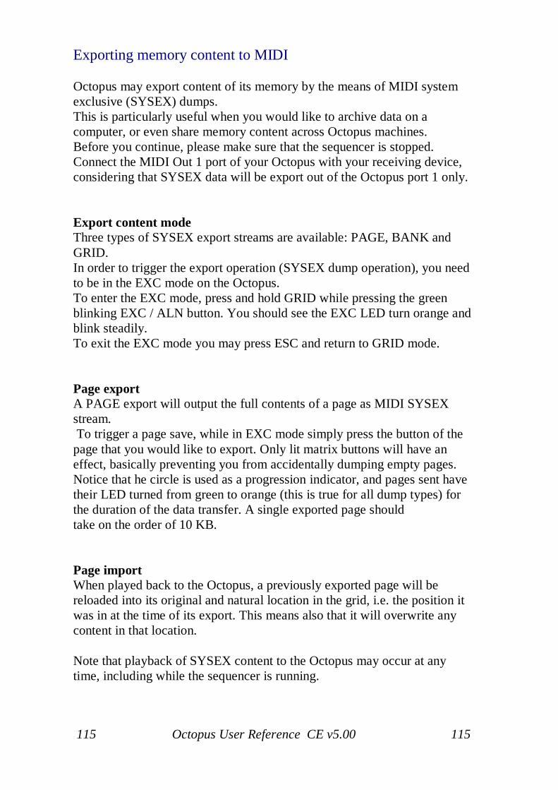
115 Octopus User Reference CE v5.00 115
Exporting memory content to MIDI
Octopus may export content of its memory by the means of MIDI systemexclusive (SYSEX) dumps.This is particularly useful when you would like to archive data on acomputer, or even share memory content across Octopus machines.Before you continue, please make sure that the sequencer is stopped.Connect the MIDI Out 1 port of your Octopus with your receiving device,considering that SYSEX data will be export out of the Octopus port 1 only.
Export content modeThree types of SYSEX export streams are available: PAGE, BANK andGRID.In order to trigger the export operation (SYSEX dump operation), you needto be in the EXC mode on the Octopus.To enter the EXC mode, press and hold GRID while pressing the greenblinking EXC / ALN button. You should see the EXC LED turn orange andblink steadily.To exit the EXC mode you may press ESC and return to GRID mode.
Page exportA PAGE export will output the full contents of a page as MIDI SYSEXstream. To trigger a page save, while in EXC mode simply press the button of thepage that you would like to export. Only lit matrix buttons will have aneffect, basically preventing you from accidentally dumping empty pages.Notice that he circle is used as a progression indicator, and pages sent havetheir LED turned from green to orange (this is true for all dump types) forthe duration of the data transfer. A single exported page shouldtake on the order of 10 KB.
Page importWhen played back to the Octopus, a previously exported page will bereloaded into its original and natural location in the grid, i.e. the position itwas in at the time of its export. This means also that it will overwrite anycontent in that location.
Note that playback of SYSEX content to the Octopus may occur at anytime, including while the sequencer is running.
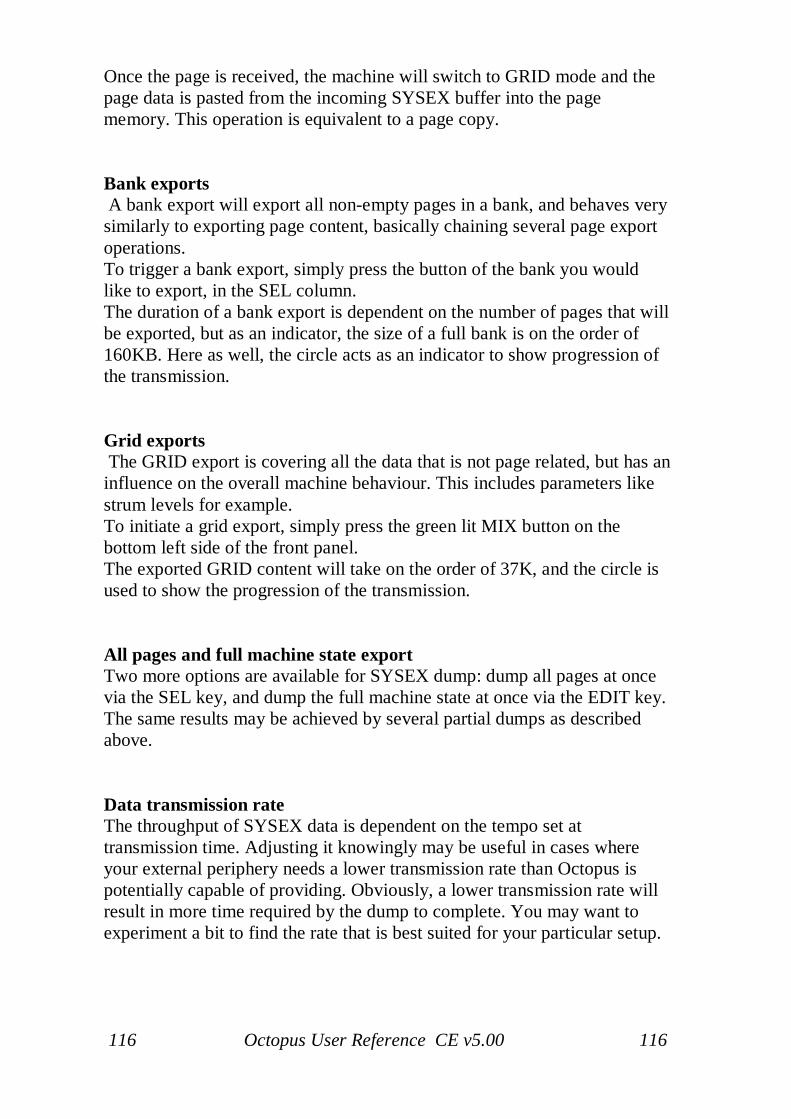
116 Octopus User Reference CE v5.00 116
Once the page is received, the machine will switch to GRID mode and thepage data is pasted from the incoming SYSEX buffer into the pagememory. This operation is equivalent to a page copy.
Bank exports A bank export will export all non-empty pages in a bank, and behaves verysimilarly to exporting page content, basically chaining several page exportoperations.To trigger a bank export, simply press the button of the bank you wouldlike to export, in the SEL column.The duration of a bank export is dependent on the number of pages that willbe exported, but as an indicator, the size of a full bank is on the order of160KB. Here as well, the circle acts as an indicator to show progression ofthe transmission.
Grid exports The GRID export is covering all the data that is not page related, but has aninfluence on the overall machine behaviour. This includes parameters likestrum levels for example.To initiate a grid export, simply press the green lit MIX button on thebottom left side of the front panel.The exported GRID content will take on the order of 37K, and the circle isused to show the progression of the transmission.
All pages and full machine state exportTwo more options are available for SYSEX dump: dump all pages at oncevia the SEL key, and dump the full machine state at once via the EDIT key.The same results may be achieved by several partial dumps as describedabove.
Data transmission rateThe throughput of SYSEX data is dependent on the tempo set attransmission time. Adjusting it knowingly may be useful in cases whereyour external periphery needs a lower transmission rate than Octopus ispotentially capable of providing. Obviously, a lower transmission rate willresult in more time required by the dump to complete. You may want toexperiment a bit to find the rate that is best suited for your particular setup.

117 Octopus User Reference CE v5.00 117
RemarksNote that you can use the export functionality only while the sequencer isstopped. This is a measure to ensure concurrent data integrity of the SYSEXdump and timing stability of the material played.You may however, receive SYSEX data while the sequencer is playing.This makes it particularly convenient to substitute memory content on thefly, during performance.

118 Octopus User Reference CE v5.00 118
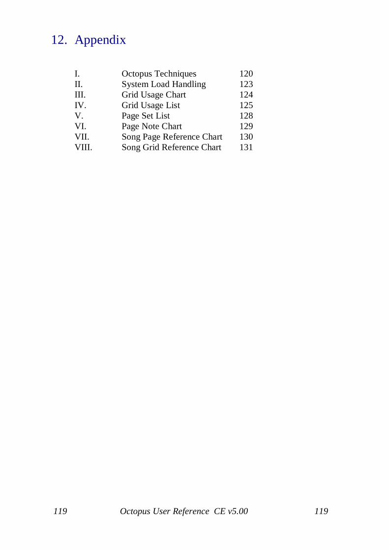
119 Octopus User Reference CE v5.00 119
12. Appendix
I. Octopus Techniques 120II. System Load Handling 123III. Grid Usage Chart 124IV. Grid Usage List 125V. Page Set List 128VI. Page Note Chart 129VII. Song Page Reference Chart 130VIII. Song Grid Reference Chart 131
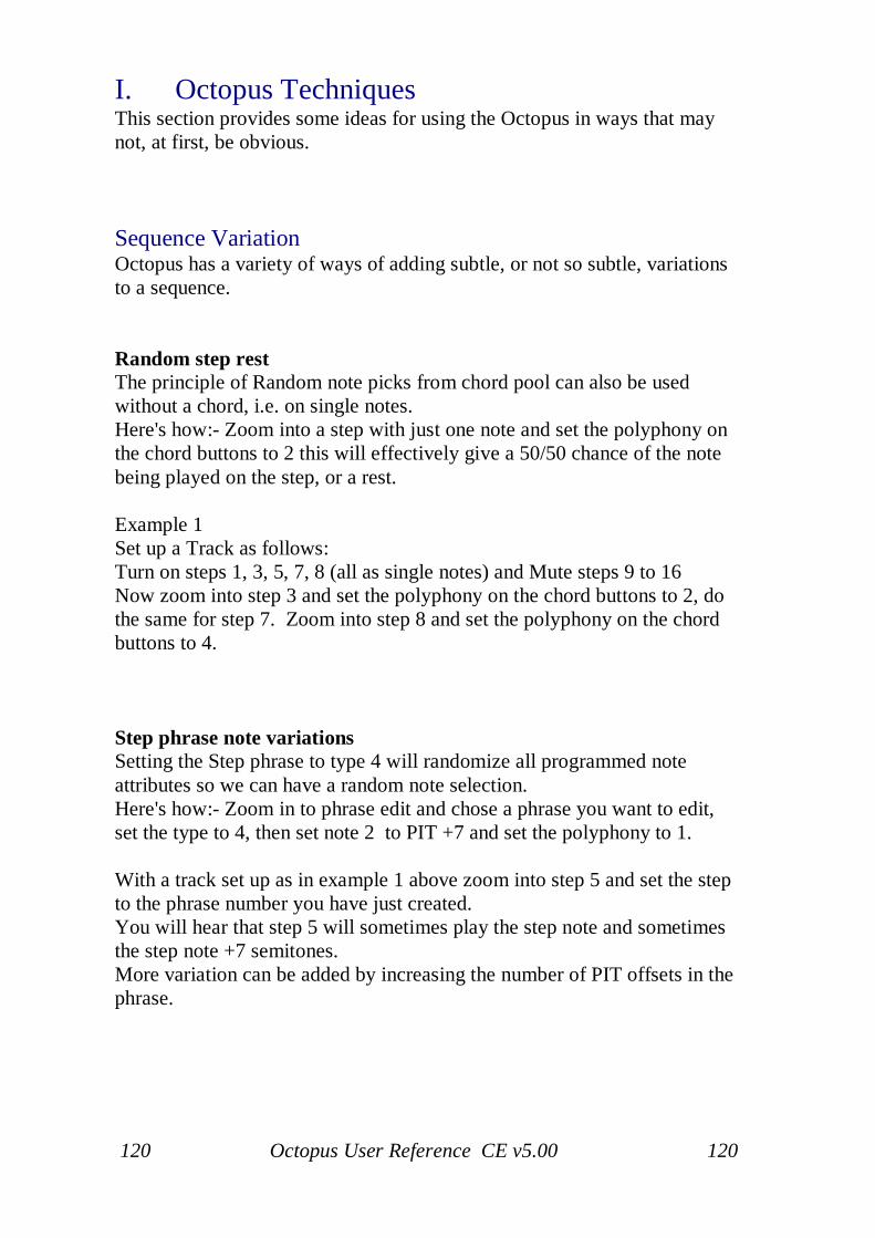
120 Octopus User Reference CE v5.00 120
I. Octopus TechniquesThis section provides some ideas for using the Octopus in ways that maynot, at first, be obvious.
Sequence VariationOctopus has a variety of ways of adding subtle, or not so subtle, variationsto a sequence.
Random step restThe principle of Random note picks from chord pool can also be usedwithout a chord, i.e. on single notes.Here's how:- Zoom into a step with just one note and set the polyphony onthe chord buttons to 2 this will effectively give a 50/50 chance of the notebeing played on the step, or a rest.
Example 1Set up a Track as follows:Turn on steps 1, 3, 5, 7, 8 (all as single notes) and Mute steps 9 to 16Now zoom into step 3 and set the polyphony on the chord buttons to 2, dothe same for step 7. Zoom into step 8 and set the polyphony on the chordbuttons to 4.
Step phrase note variationsSetting the Step phrase to type 4 will randomize all programmed noteattributes so we can have a random note selection.Here's how:- Zoom in to phrase edit and chose a phrase you want to edit,set the type to 4, then set note 2 to PIT +7 and set the polyphony to 1.
With a track set up as in example 1 above zoom into step 5 and set the stepto the phrase number you have just created.You will hear that step 5 will sometimes play the step note and sometimesthe step note +7 semitones.More variation can be added by increasing the number of PIT offsets in thephrase.
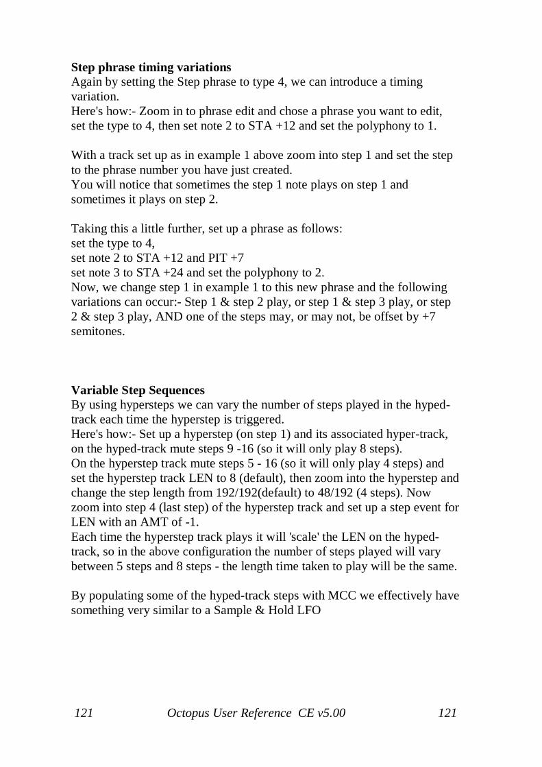
121 Octopus User Reference CE v5.00 121
Step phrase timing variationsAgain by setting the Step phrase to type 4, we can introduce a timingvariation.Here's how:- Zoom in to phrase edit and chose a phrase you want to edit,set the type to 4, then set note 2 to STA +12 and set the polyphony to 1.
With a track set up as in example 1 above zoom into step 1 and set the stepto the phrase number you have just created.You will notice that sometimes the step 1 note plays on step 1 andsometimes it plays on step 2.
Taking this a little further, set up a phrase as follows:set the type to 4,set note 2 to STA +12 and PIT +7set note 3 to STA +24 and set the polyphony to 2.Now, we change step 1 in example 1 to this new phrase and the followingvariations can occur:- Step 1 & step 2 play, or step 1 & step 3 play, or step2 & step 3 play, AND one of the steps may, or may not, be offset by +7semitones.
Variable Step SequencesBy using hypersteps we can vary the number of steps played in the hyped-track each time the hyperstep is triggered.Here's how:- Set up a hyperstep (on step 1) and its associated hyper-track,on the hyped-track mute steps 9 -16 (so it will only play 8 steps).On the hyperstep track mute steps 5 - 16 (so it will only play 4 steps) andset the hyperstep track LEN to 8 (default), then zoom into the hyperstep andchange the step length from 192/192(default) to 48/192 (4 steps). Nowzoom into step 4 (last step) of the hyperstep track and set up a step event forLEN with an AMT of -1.Each time the hyperstep track plays it will 'scale' the LEN on the hyped-track, so in the above configuration the number of steps played will varybetween 5 steps and 8 steps - the length time taken to play will be the same.
By populating some of the hyped-track steps with MCC we effectively havesomething very similar to a Sample & Hold LFO
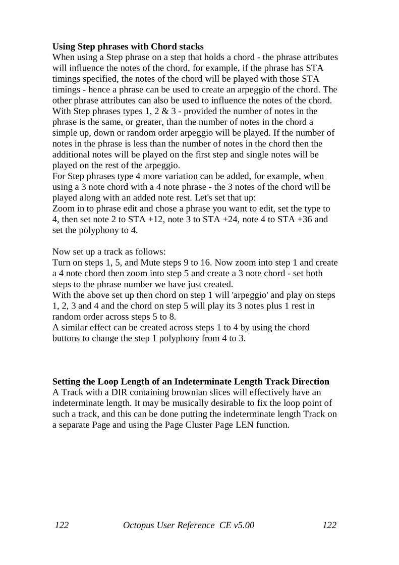
122 Octopus User Reference CE v5.00 122
Using Step phrases with Chord stacksWhen using a Step phrase on a step that holds a chord - the phrase attributeswill influence the notes of the chord, for example, if the phrase has STAtimings specified, the notes of the chord will be played with those STAtimings - hence a phrase can be used to create an arpeggio of the chord. Theother phrase attributes can also be used to influence the notes of the chord.With Step phrases types 1, 2 & 3 - provided the number of notes in thephrase is the same, or greater, than the number of notes in the chord asimple up, down or random order arpeggio will be played. If the number ofnotes in the phrase is less than the number of notes in the chord then theadditional notes will be played on the first step and single notes will beplayed on the rest of the arpeggio.For Step phrases type 4 more variation can be added, for example, whenusing a 3 note chord with a 4 note phrase - the 3 notes of the chord will beplayed along with an added note rest. Let's set that up:Zoom in to phrase edit and chose a phrase you want to edit, set the type to4, then set note 2 to STA +12, note 3 to STA +24, note 4 to STA +36 andset the polyphony to 4.
Now set up a track as follows:Turn on steps 1, 5, and Mute steps 9 to 16. Now zoom into step 1 and createa 4 note chord then zoom into step 5 and create a 3 note chord - set bothsteps to the phrase number we have just created.With the above set up then chord on step 1 will 'arpeggio' and play on steps1, 2, 3 and 4 and the chord on step 5 will play its 3 notes plus 1 rest inrandom order across steps 5 to 8.A similar effect can be created across steps 1 to 4 by using the chordbuttons to change the step 1 polyphony from 4 to 3.
Setting the Loop Length of an Indeterminate Length Track DirectionA Track with a DIR containing brownian slices will effectively have anindeterminate length. It may be musically desirable to fix the loop point ofsuch a track, and this can be done putting the indeterminate length Track ona separate Page and using the Page Cluster Page LEN function.
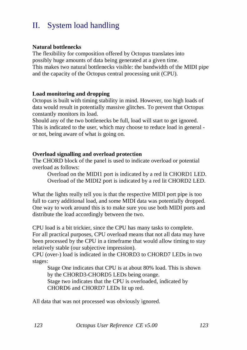
123 Octopus User Reference CE v5.00 123
II. System load handling
Natural bottlenecksThe flexibility for composition offered by Octopus translates intopossibly huge amounts of data being generated at a given time.This makes two natural bottlenecks visible: the bandwidth of the MIDI pipeand the capacity of the Octopus central processing unit (CPU).
Load monitoring and droppingOctopus is built with timing stability in mind. However, too high loads ofdata would result in potentially massive glitches. To prevent that Octopusconstantly monitors its load.Should any of the two bottlenecks be full, load will start to get ignored.This is indicated to the user, which may choose to reduce load in general -or not, being aware of what is going on.
Overload signalling and overload protectionThe CHORD block of the panel is used to indicate overload or potentialoverload as follows:
Overload on the MIDI1 port is indicated by a red lit CHORD1 LED.Overload of the MIDI2 port is indicated by a red lit CHORD2 LED.
What the lights really tell you is that the respective MIDI port pipe is toofull to carry additional load, and some MIDI data was potentially dropped.One way to work around this is to make sure you use both MIDI ports anddistribute the load accordingly between the two.
CPU load is a bit trickier, since the CPU has many tasks to complete.For all practical purposes, CPU overload means that not all data may havebeen processed by the CPU in a timeframe that would allow timing to stayrelatively stable (our subjective impression).CPU (over-) load is indicated in the CHORD3 to CHORD7 LEDs in twostages:
Stage One indicates that CPU is at about 80% load. This is shown by the CHORD3-CHORD5 LEDs being orange.Stage two indicates that the CPU is overloaded, indicated by CHORD6 and CHORD7 LEDs lit up red.
All data that was not processed was obviously ignored.
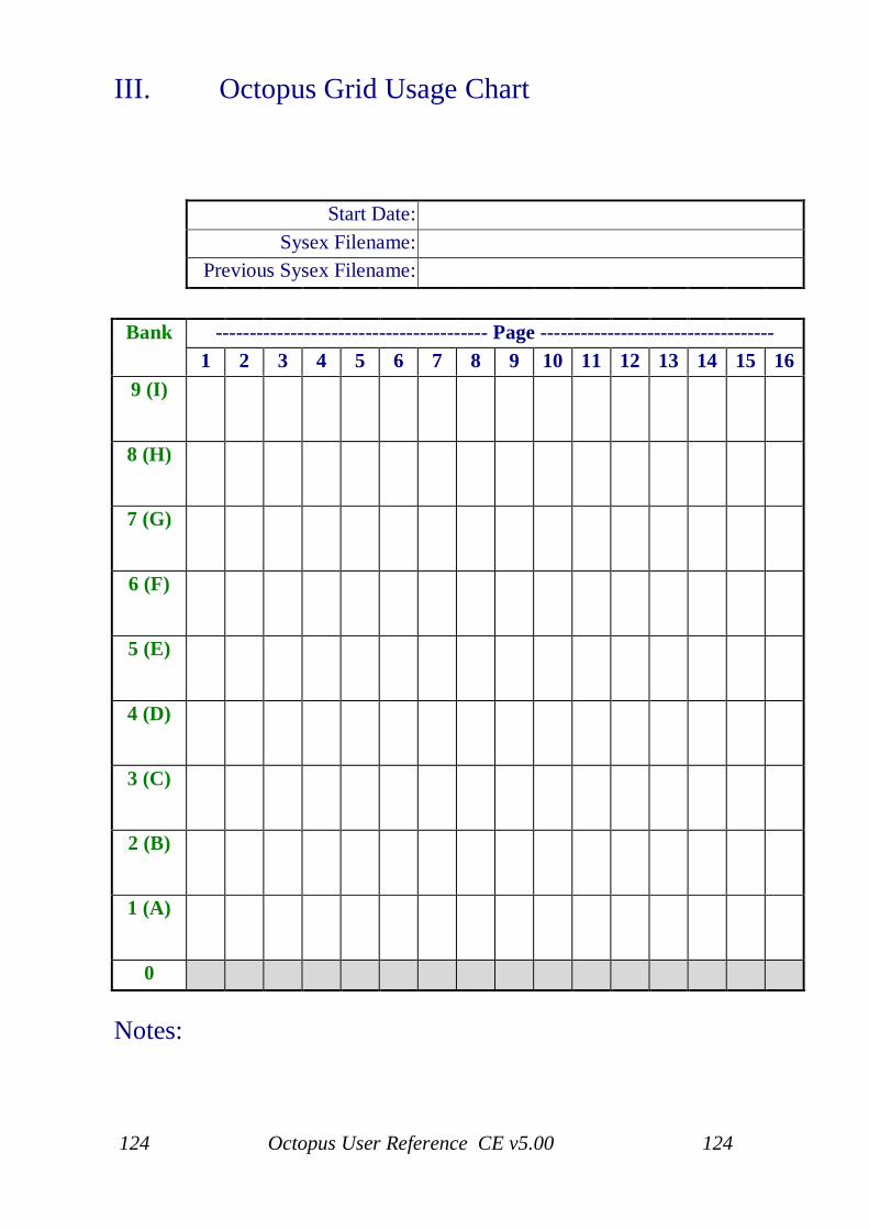
124 Octopus User Reference CE v5.00 124
III. Octopus Grid Usage Chart
Start Date:Sysex Filename:
Previous Sysex Filename:
---------------------------------------- Page -----------------------------------Bank1 2 3 4 5 6 7 8 9 10 11 12 13 14 15 16
9 (I)
8 (H)
7 (G)
6 (F)
5 (E)
4 (D)
3 (C)
2 (B)
1 (A)
0
Notes:
125 Octopus User Reference CE v5.00 125
IV. Octopus Grid Usage List
Bank Page Song / Instrument BPM Page Song / Instrument BPM
1 92 103 114 125 136 147 15
9 (I)
8 16
Bank Page Song / Instrument BPM Page Song / Instrument BPM
1 92 103 114 125 136 147 15
8 (H)
8 16
Bank Page Song / Instrument BPM Page Song / Instrument BPM
1 92 103 114 125 136 147 15
7 (G)
8 16
126 Octopus User Reference CE v5.00 126
IV. Octopus Grid Usage List (cont.)
Bank Page Song / Instrument BPM Page Song / Instrument BPM
1 92 103 114 125 136 147 15
6 (F)
8 16
Bank Page Song / Instrument BPM Page Song / Instrument BPM
1 92 103 114 125 136 147 15
5 (E)
8 16
Bank Page Song / Instrument BPM Page Song / Instrument BPM
1 92 103 114 125 136 147 15
4 (D)
8 16
127 Octopus User Reference CE v5.00 127
IV. Octopus Grid Usage List (cont.)
Bank Page Song / Instrument BPM Page Song / Instrument BPM
1 92 103 114 125 136 147 15
3 (C)
8 16
Bank Page Song / Instrument BPM Page Song / Instrument BPM
1 92 103 114 125 136 147 15
2 (B)
8 16
Bank Page Song / Instrument BPM Page Song / Instrument BPM
1 92 103 114 125 136 147 15
1 (A)
8 16
128 Octopus User Reference CE v5.00 128
V. Page Set List
Page Set ----------- Bank / Page (A1-I16) ---------- Song Name1
2
3
4
5
6
7
8
9
10
11
12
13
14
15
16
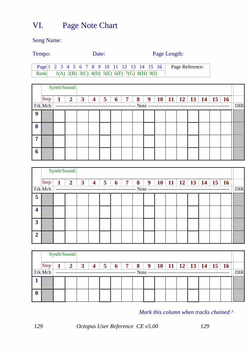
129 Octopus User Reference CE v5.00 129
VI. Page Note Chart
Song Name:
Tempo: Date: Page Length:
Page 1 2 3 4 5 6 7 8 9 10 11 12 13 14 15 16Bank 1(A) 2(B) 3(C) 4(D) 5(E) 6(F) 7(G) 8(H) 9(I)
Page Reference:
Synth/Sound:
Step 1 2 3 4 5 6 7 8 9 10 11 12 13 14 15 16Trk Mch ------------------------------------------------ Note ------------------------------------------------ DIR
9
8
7
6
Synth/Sound:
Step 1 2 3 4 5 6 7 8 9 10 11 12 13 14 15 16Trk Mch ------------------------------------------------ Note ------------------------------------------------ DIR
5
4
3
2
Synth/Sound:
Step 1 2 3 4 5 6 7 8 9 10 11 12 13 14 15 16Trk Mch ------------------------------------------------ Note ------------------------------------------------ DIR
1
0
Mark this column when tracks chained ^
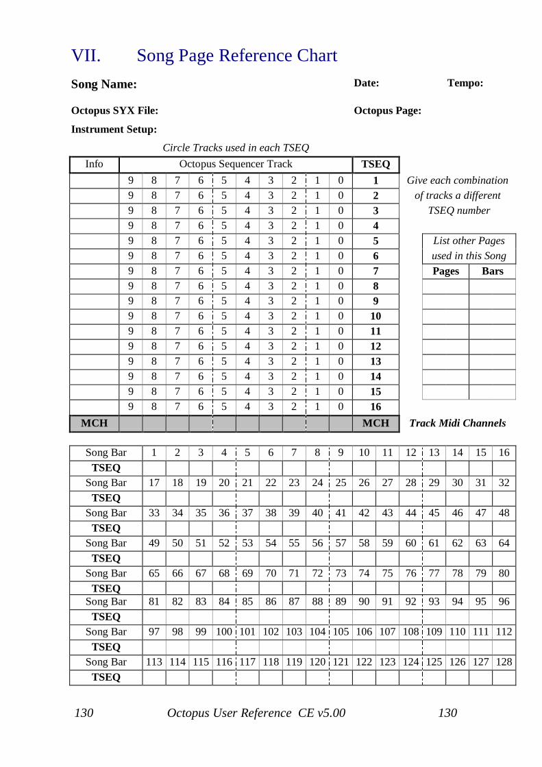
130 Octopus User Reference CE v5.00 130
VII. Song Page Reference ChartSong Name: Date: Tempo:
Octopus SYX File: Octopus Page:
Instrument Setup:
Circle Tracks used in each TSEQInfo Octopus Sequencer Track TSEQ
9 8 7 6 5 4 3 2 1 0 1 Give each combination9 8 7 6 5 4 3 2 1 0 2 of tracks a different9 8 7 6 5 4 3 2 1 0 3 TSEQ number9 8 7 6 5 4 3 2 1 0 49 8 7 6 5 4 3 2 1 0 5 List other Pages9 8 7 6 5 4 3 2 1 0 6 used in this Song9 8 7 6 5 4 3 2 1 0 7 Pages Bars9 8 7 6 5 4 3 2 1 0 89 8 7 6 5 4 3 2 1 0 99 8 7 6 5 4 3 2 1 0 109 8 7 6 5 4 3 2 1 0 119 8 7 6 5 4 3 2 1 0 129 8 7 6 5 4 3 2 1 0 139 8 7 6 5 4 3 2 1 0 149 8 7 6 5 4 3 2 1 0 159 8 7 6 5 4 3 2 1 0 16
MCH MCH Track Midi Channels
Song Bar 1 2 3 4 5 6 7 8 9 10 11 12 13 14 15 16TSEQ
Song Bar 17 18 19 20 21 22 23 24 25 26 27 28 29 30 31 32TSEQ
Song Bar 33 34 35 36 37 38 39 40 41 42 43 44 45 46 47 48TSEQ
Song Bar 49 50 51 52 53 54 55 56 57 58 59 60 61 62 63 64TSEQ
Song Bar 65 66 67 68 69 70 71 72 73 74 75 76 77 78 79 80TSEQ
Song Bar 81 82 83 84 85 86 87 88 89 90 91 92 93 94 95 96TSEQ
Song Bar 97 98 99 100 101 102 103 104 105 106 107 108 109 110 111 112TSEQ
Song Bar 113 114 115 116 117 118 119 120 121 122 123 124 125 126 127 128TSEQ
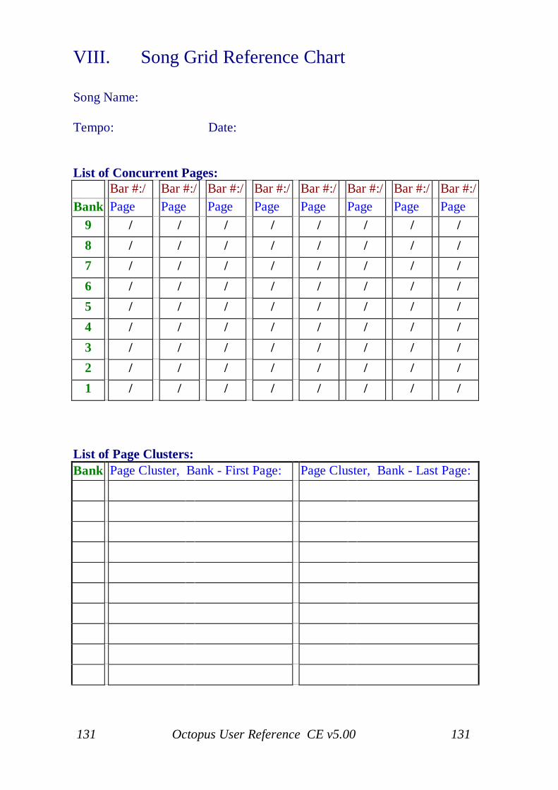
131 Octopus User Reference CE v5.00 131
VIII. Song Grid Reference Chart
Song Name:
Tempo: Date:
List of Concurrent Pages:Bar #:/ Bar #:/ Bar #:/ Bar #:/ Bar #:/ Bar #:/ Bar #:/ Bar #:/
Bank Page Page Page Page Page Page Page Page9 / / / / / / / /8 / / / / / / / /7 / / / / / / / /6 / / / / / / / /5 / / / / / / / /4 / / / / / / / /3 / / / / / / / /2 / / / / / / / /1 / / / / / / / /
List of Page Clusters:Bank Page Cluster, Bank - First Page: Page Cluster, Bank - Last Page:

132 Octopus User Reference CE v5.00 132