Embed Size (px)
Citation preview
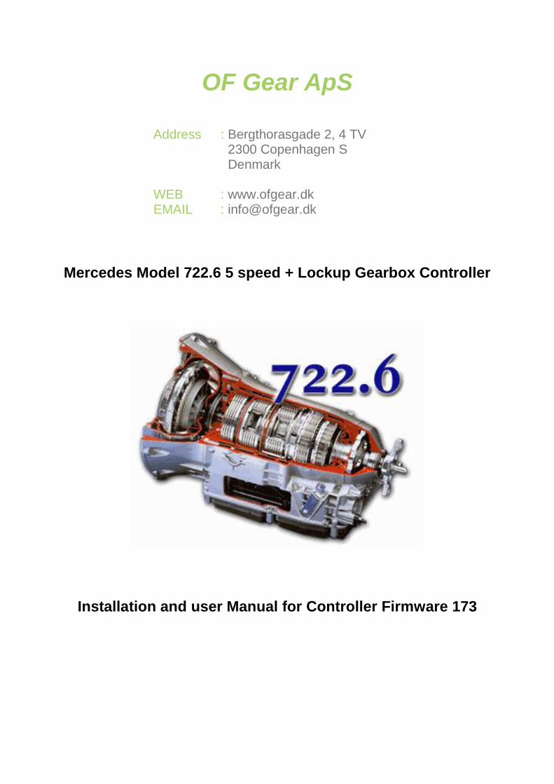
OF Gear ApS
Address : Bergthorasgade 2, 4 TV
2300 Copenhagen S
Denmark
WEB : www.ofgear.dk EMAIL : [email protected]
Mercedes Model 722.6 5 speed + Lockup Gearbox Controller
Installation and user Manual for Controller Firmware 173
1. Product introduction ..................................................................................................... 4
2. Installation of the system .............................................................................................. 5 2.1 Identifying the controller components .............................................................................. 5 2.2 External Parts needed ......................................................................................................... 6
TPS Sensor ............................................................................................................................. 6 Gear Lever and plug................................................................................................................ 6 722.6 Gearbox ........................................................................................................................ 7
2.3 Installing the controller ..................................................................................................... 10 Controller pin-out diagram .................................................................................................................. 11 Connecting the TPS sensor ................................................................................................................ 13
Connecting the controller for gearbox control ........................................................................ 14 Connecting the Gear Lever Connection 10 PIN MB plug to 14 Controller plug ................................. 14 Connecting the 24 Pin Gearbox Plug to the controller plug ............................................................... 15 Connecting Tiptronic (Optional) or paddle shift .................................................................................. 16 Connecting Reverse Ligth (Those 2 pin it shorted when i R for Reverse Ligth) ................................ 16 Connecting Starter Lockout (Optional) ............................................................................................... 17
Connecting the controller for boost control ............................................................................ 18 Vacuum actuator for vacuum actuated turbos .................................................................................... 18 Connecting the boost and EGP sensor .............................................................................................. 18
2.4 Initial Quick Setup ............................................................................................................. 20 Caibrate the TPS ................................................................................................................... 20 Setup the Gear Lever ............................................................................................................ 20 Define the Load ..................................................................................................................... 20 Setup the how to define RPM and Speed .............................................................................. 21 Setup the shift firmness ......................................................................................................... 21
3. User manual for gearbox control................................................................................ 22 3.1 Controller Menu ................................................................................................................. 22 3.2 Live Data Dashboards ....................................................................................................... 23
Live Data Dashboard 1 .......................................................................................................... 23 Live Data Dashboard 2 .......................................................................................................... 24 Live Data Dashboard 3 .......................................................................................................... 24
3.3 Manual Shift ....................................................................................................................... 24 3.4 Setup Parameters .............................................................................................................. 25
Setup TPS ............................................................................................................................. 25 LOAD – TPS Boost; Boost part load ...................................................................................... 25 Converter Lockup; Converter Unlock; Lockup 2-4 gear ......................................................... 26 TPS Speed 25%; TPS Speed 50%; TPS Speed 75% ............................................................ 26 Volt reg 100%........................................................................................................................ 26 Temp reg +/- ......................................................................................................................... 26 Kickdown at %TPS ................................................................................................................ 26 Fail Handling ......................................................................................................................... 26 Max speed fail ....................................................................................................................... 26 Slow upshift ........................................................................................................................... 26 PWM N->D P->R ................................................................................................................... 26 PWM 3-4 N-D/P .................................................................................................................... 26 RPM INT/EXT; Adjust ext RPM ............................................................................................. 27 Speed in/EXT; EXT Speed %; INT Speed % ......................................................................... 27 Delay 3-4 ............................................................................................................................... 27 Reset km ............................................................................................................................... 27 Lockup Soft/hard ................................................................................................................... 27 Use Paddle ........................................................................................................................... 28 Start up display ..................................................................................................................... 28 Lever setup ........................................................................................................................... 28 Idle RPM <500 no ................................................................................................................. 28 Time bet M shift ..................................................................................................................... 28
LineRegTime ........................................................................................................................ 28l PresTegTime......................................................................................................................... 28 ShiftValve Time ..................................................................................................................... 28 1-2 Soft high RPM ................................................................................................................. 28 Tacho out .............................................................................................................................. 28
3.4 Shift Speeds ...................................................................................................................... 31 3.5 Shift Firmness ................................................................................................................... 32 3.6 Rate Last Shift MENU ........................................................................................................ 36
4. User manual for boost control .................................................................................... 37
5. Using a laptop with your controller ............................................................................ 46 Updating firmware ................................................................................................................... 46 Setting up the controller using a Laptop ............................................................................... 48
6. Troubleshooting........................................................................................................... 51
LEFTOVER CONTENT TO PROCESS ............................................................................. 52
1. Product introduction The OF Gear kit is able to function as a controller for the Mercedes 722.6 gearbox and can function as a
boost controller for specific VNT turbos. The system is not intended for on road use. Be advised that the
system will produce changes in the drivability of your vehicle. If installed, setup or used incorrectly, your
engine and transmission can get permanently damaged, or worse. This product comes with no warranties or
guarantees of any kind. Both installation and use of this system in any vehicle is done at the risk of the owner
/ operator of the vehicle.
This document provides an overview of how this system has been used in the past, however installation of
the system of your specific application is your full responsibility and might be different from what is
described in this document. All references made refer to the latest firmware for the gen 3 controllers.
The developer of this system cannot be held responsible for any loss; damages or injury caused either directly
or indirectly by the installation or use of this system.
2. Installation of the system
2.1 Identifying the controller components
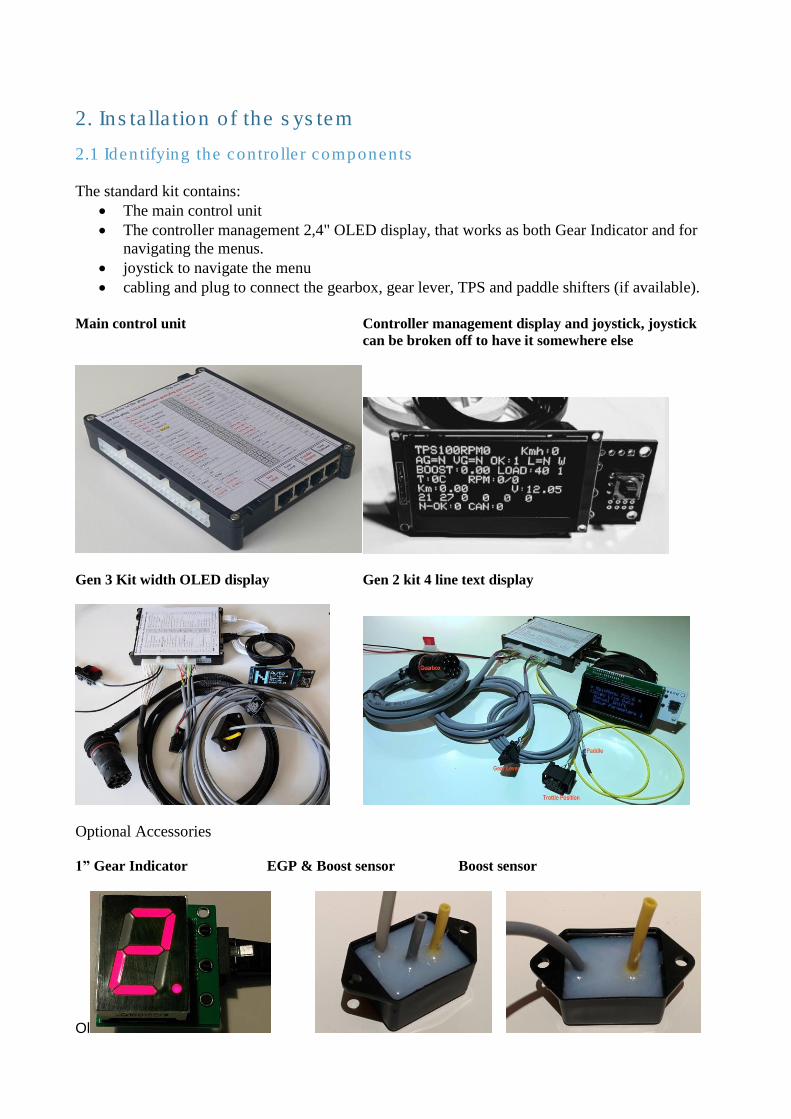
The standard kit contains:
• The main control unit
• The controller management 2,4" OLED display, that works as both Gear Indicator and for
navigating the menus.
• joystick to navigate the menu
• cabling and plug to connect the gearbox, gear lever, TPS and paddle shifters (if available).
Main control unit Controller management display and joystick, joystick
can be broken off to have it somewhere else
Gen 3 Kit width OLED display Gen 2 kit 4 line text display
Optional Accessories 1” Gear Indicator EGP & Boost sensor Boost sensor
Ol
The pressure sensors are professional type supplied by www.Mouser.com. A gel coating protects them
from harsh environments and they measure max 3 bar boost/EGP over environmental pressure.
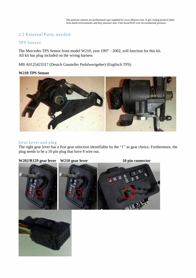
2.2 External Parts needed
TPS Sensor
The Mercedes TPS Sensor from model W210, year 1997 – 2002, will function for this kit.
All kit has plug included on the wiring harness
MB A0125423317 (Deutch Gassteller Pedalwertgeber) (Englisch TPS)
W210 TPS Sensor
Gear Lever and plug The right gear lever has a first gear selection identifiable by the “1” as gear choice. Furthermore, the
plug needs to be a 10 pin plug that have 8 wire out.
W202/R129 gear lever W210 gear lever 10 pin connector
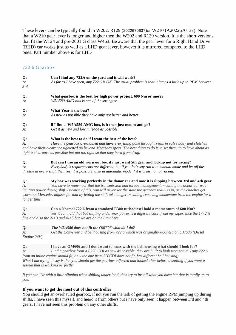
These levers can be typically found in W202, R129 (2022670637)or W210 (A2022670137), Note
that a W210 gear lever is longer and higher then the W202 and R129 version. It is the short versions
that fit the W124 and pre-2001 G class W463. Be aware that the gear lever for a Right Hand Drive
(RHD) car works just as well as a LHD gear lever, however it is mirrored compared to the LHD
ones. Part number above is for LHD
722.6 Gearbox Q: Can I find any 722.6 on the yard and it will work? A: As far as I have seen, any 722.6 is OK. The usual problem is that it jumps a little up in RPM between
3-4 Q: What gearbox is the best for high power project. 600 Nm or more? A: W5A580 AMG box is one of the strongest. Q: What Year is the best? A: As new as possible they have only got better and better. Q: if I find a W5A580 AMG box, is it then just mount and go? A: Get it as new and low mileage as possible Q: What is the best to do if i want the best of the best? A: Have the gearbox overhauled and have everything gone through; seals in valve body and clutches
and have their clearance tightened up beyond Mercedes specs. The best thing to do is to set them up to have about as
tight a clearance as possible but not too tight so that they burn from drag. Q: But can I use an old worn out box if i just want 5th gear and lockup not for racing? A: Everybody’s requirements are different, but if you let’s say run it in manual mode and let off the
throttle at every shift, then yes, it is possible, also in automatic mode if it is cruising not racing. Q: My box was working perfectly in the donor car and now it is slipping between 3rd and 4th gear. A: You have to remember that the transmission had torque management, meaning the donar car was
limiting power during shift. Because of this, you will never see the state the gearbox really is in, as the clutches get
worn out Mercedes adjusts for that by letting the shift take longer, meaning removing momentum from the engine for a
longer time. Q: Can a Normal 722.6 from a standard E300 turbodiesel hold a momentum of 600 Nm? A: Yes it can hold that but shifting under max power is a different case, from my experience the 1->2 is
fine and also the 2->3 and 4->5 but we are on the limit here. Q: The W5A580 does not fit the OM606 what do I do? A: Get the Converter and bellhousing from 722.6 which was originally mounted on OM606 (Diesel
Engine 24V) Q: I have an OM606 and I dont want to mess with the bellhousing what should I look for? A: Find a gearbox from a E270 CDI as new as possible, they are built to high momentum. (Any 722.6
from an inline engine should fit, only the one from 320CDI does not fit, has different bell housing) What I am trying to say is that you should get the gearbox adjusted and looked after before installing if you want a
system that is working perfectly. If you can live with a little slipping when shifting under load, then try to install what you have but that is totally up to
you.
If you want to get the most out of this controller You should get an overhauled gearbox, if not you run the risk of getting the engine RPM jumping up during
shifts, I have seen this myself, and heard it from others but i have only seen it happen between 3rd and 4th
gears. I have not seen this problem on any other shifts.

If you want to shift gear under 100% load I am just preparing you that you can see a jump in RPM between
3rd and 4th gears.
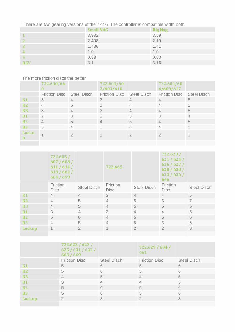
There are two gearing versions of the 722.6. The controller is compatible width both.
Small NAG Big Nag
1 3.932 3.59
2 2.408 2.19
3 1.486 1.41
4 1.0 1.0
5 0.83 0.83
REV 3.1 3.16
The more friction discs the better
722.600/660
722.601/602/603/610
722.604/606/609/617
Friction Disc Steel Disch Friction Disc Steel Disch Friction Disc Steel Disch
K1 3 4 3 4 4 5
K2 4 5 3 4 4 5
K3 3 4 3 4 4 5
B1 2 3 2 3 3 4
B2 4 5 4 5 4 5
B3 3 4 3 4 4 5
Lockup
1 2 1 2 2 3
722.605 / 607 / 608 / 611 / 614 / 618 / 662 / 664 / 699
722.665
722.620 / 621 / 624 / 626 / 627 / 628 / 630 / 633 / 636 / 666
Friction Disc
Steel Disch Friction Disc
Steel Disch Friction Disc
Steel Disch
K1 4 4 3 4 4 5
K2 4 5 4 5 6 7
K3 4 5 4 5 5 6
B1 3 4 3 4 4 5
B2 5 6 4 5 5 6
B3 4 5 4 5 5 6
Lockup 1 2 1 2 2 3
722.622 / 623 / 625 / 631 / 632 / 663 / 669
722.629 / 634 / 661
Friction Disc Steel Disch Friction Disc Steel Disch
K1 5 6 5 6
K2 5 6 5 6
K3 4 5 4 5
B1 3 4 4 5
B2 5 6 5 6
B3 5 6 5 6
Lockup 2 3 2 3

2.3 Installing the controller
1. Gearbox: Connect the large, round, multi-pin plug directly to the gearbox
2. Gear lever: Connect the rectangular gear level plug to the gear lever
3. TPS: Connect the TPS sensor plug to the TPS sensor
4. Connecting Power
• Black to ground makes sure you have a good connection.
• Red to a 12V supply that becomes live when the ignition is switched on. Use an 8 Amp fuse
on this wire.
Example of Gen 2 kit connected
Boost solenoid / EGP sensor / boost sensor. Only needed if used as boost
controller
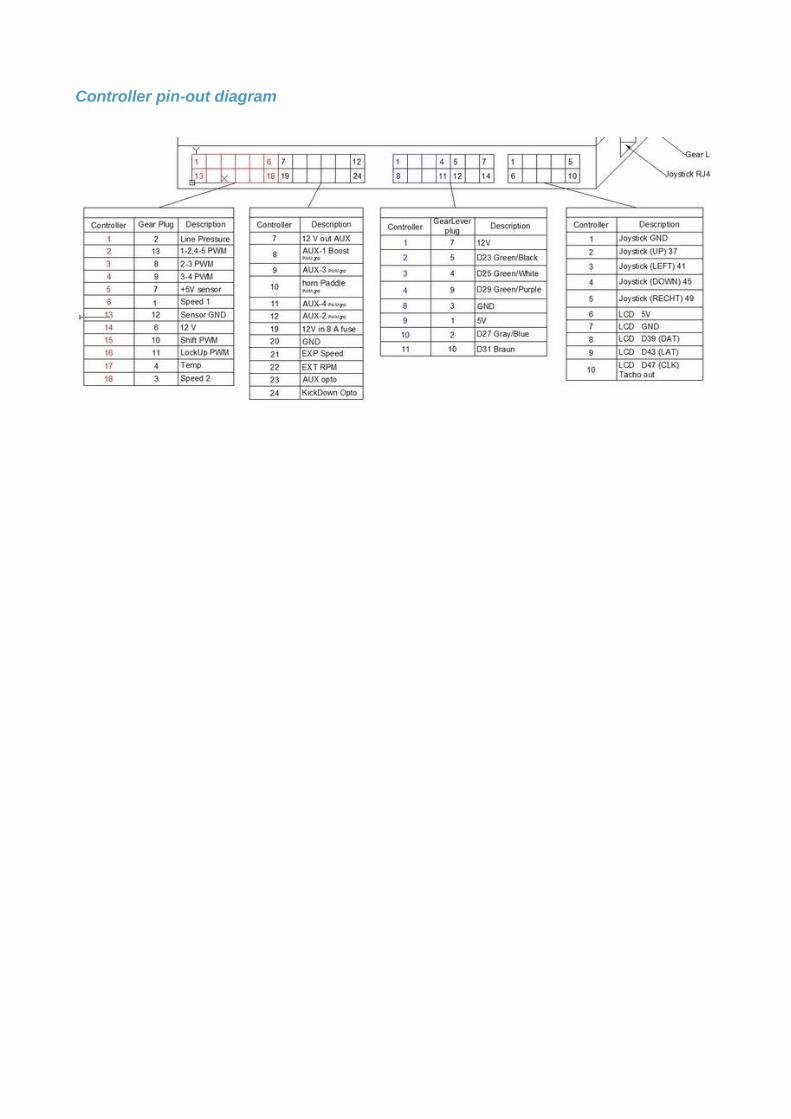
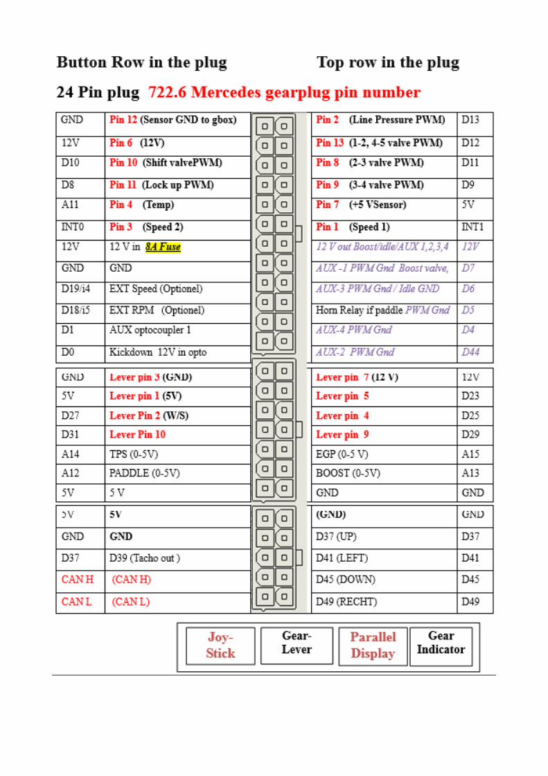
Controller pin-out diagram
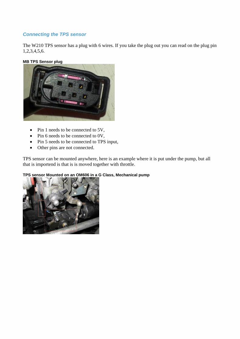
Connecting the TPS sensor
The W210 TPS sensor has a plug with 6 wires. If you take the plug out you can read on the plug pin
1,2,3,4,5,6.
MB TPS Sensor plug
• Pin 1 needs to be connected to 5V,
• Pin 6 needs to be connected to 0V,
• Pin 5 needs to be connected to TPS input,
• Other pins are not connected.
TPS sensor can be mounted anywhere, here is an example where it is put under the pump, but all
that is importend is that is is moved together with throttle.
TPS sensor Mounted on an OM606 in a G Class, Mechanical pump
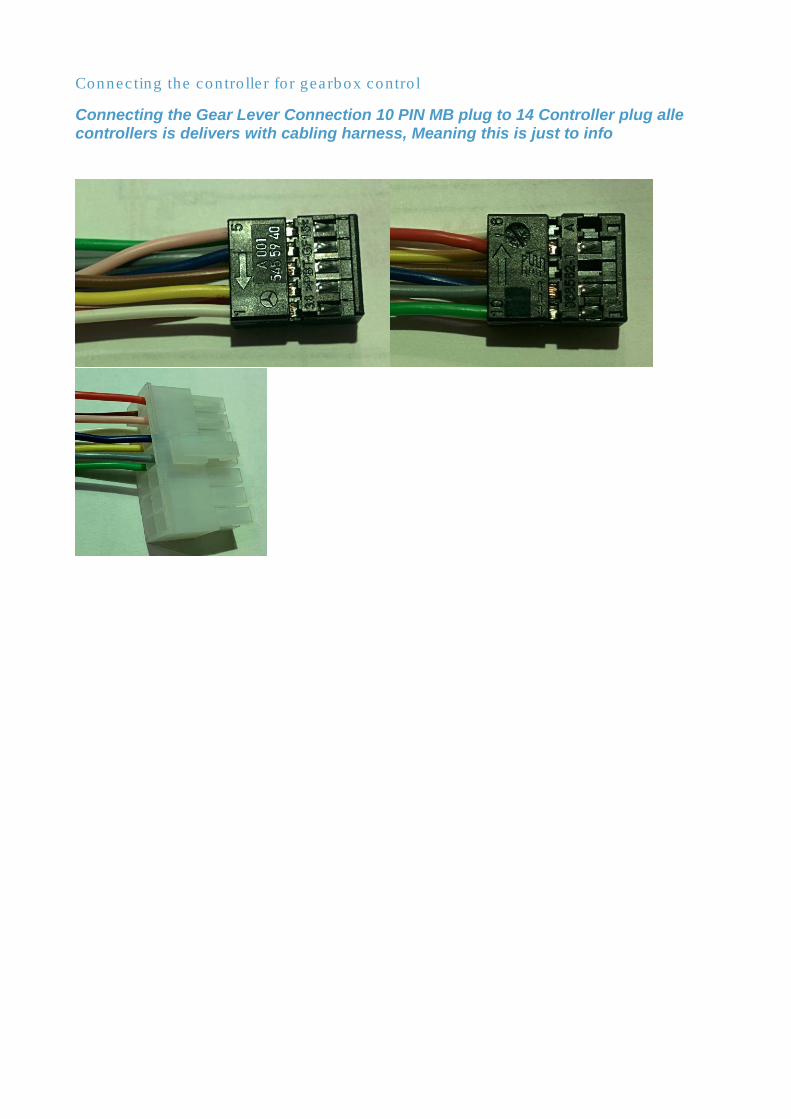
Connecting the controller for gearbox control
Connecting the Gear Lever Connection 10 PIN MB plug to 14 Controller plug alle controllers is delivers with cabling harness, Meaning this is just to info
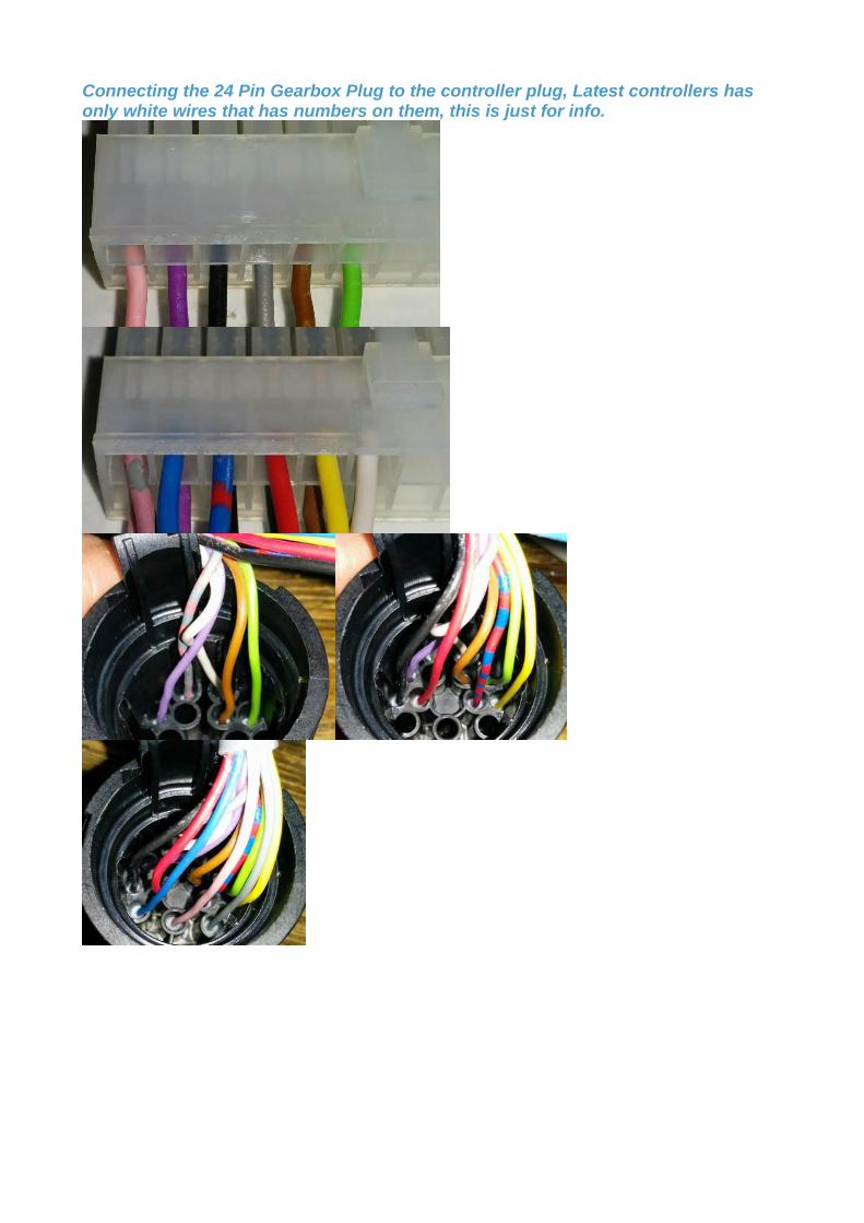
Connecting the 24 Pin Gearbox Plug to the controller plug, Latest controllers has only white wires that has numbers on them, this is just for info.
Connecting Tiptronic (Optional) or paddle shift I can NOT talk to the Tiptronic shifter, if you want to use that, it is fine but you then have no switch
for W/S but that can be any switch.
And I can only tell from the gearbox if you are in P/N od R/D but that is fine but the function width
hold in 4, 3 2, 1, and so on are not working.
If you want to use +/- You have to add some micro switch to switch to ground when you press + or
- and then connect to PADDLE input, that’s it.
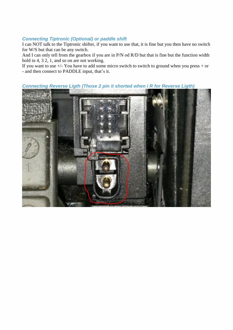
Connecting Reverse Ligth (Those 2 pin it shorted when i R for Reverse Ligth)
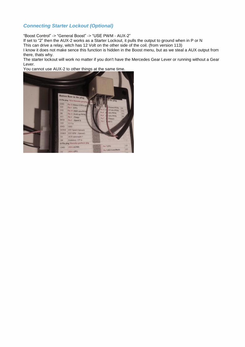
Connecting Starter Lockout (Optional) “Boost Control” -> “General Boost” -> “USE PWM - AUX-2” If set to “2” then the AUX-2 works as a Starter Lockout, it pulls the output to ground when in P or N This can drive a relay, witch has 12 Volt on the other side of the coil. (from version 113) I know it does not make sence this function is hidden in the Boost menu, but as we steal a AUX output from there, thats why. The starter lockout will work no matter if you don't have the Mercedes Gear Lever or running without a Gear Lever. You cannot use AUX-2 to other things at the same time.
Connecting the controller for boost control
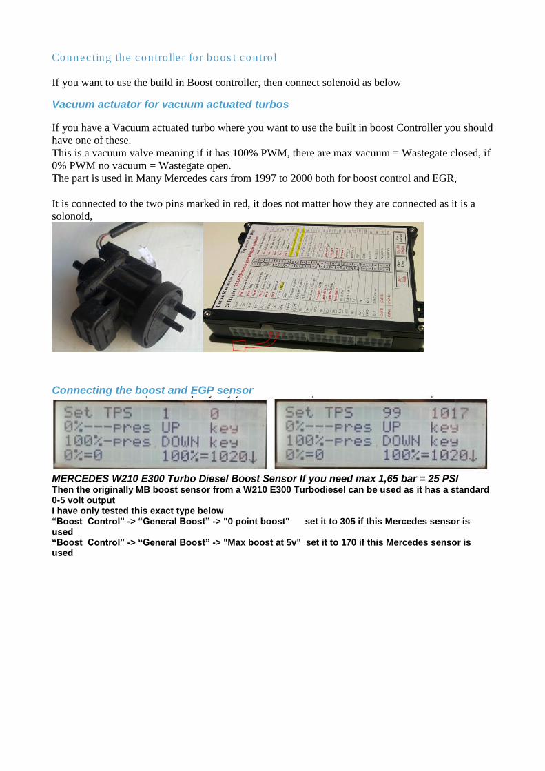
If you want to use the build in Boost controller, then connect solenoid as below
Vacuum actuator for vacuum actuated turbos
If you have a Vacuum actuated turbo where you want to use the built in boost Controller you should
have one of these.
This is a vacuum valve meaning if it has 100% PWM, there are max vacuum = Wastegate closed, if
0% PWM no vacuum = Wastegate open.
The part is used in Many Mercedes cars from 1997 to 2000 both for boost control and EGR,
It is connected to the two pins marked in red, it does not matter how they are connected as it is a
solonoid,
Connecting the boost and EGP sensor
MERCEDES W210 E300 Turbo Diesel Boost Sensor If you need max 1,65 bar = 25 PSI Then the originally MB boost sensor from a W210 E300 Turbodiesel can be used as it has a standard 0-5 volt output I have only tested this exact type below “Boost Control” -> “General Boost” -> "0 point boost" set it to 305 if this Mercedes sensor is used “Boost Control” -> “General Boost” -> "Max boost at 5v" set it to 170 if this Mercedes sensor is used
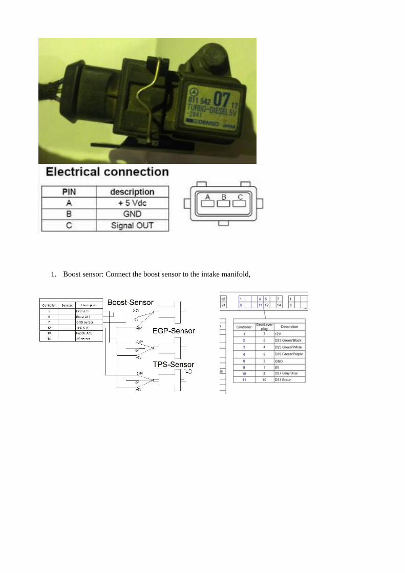
1. Boost sensor: Connect the boost sensor to the intake manifold,
2.4 Initial Quick Setup
The below steps will allow you to control the gearbox, but it is NOT adequate to make it shift
properly. For proper working of the controller, a detailed setup is required for your car (weight,
power, gear ratios) and your driving style by adjusting and fine-tuning all the options provided.
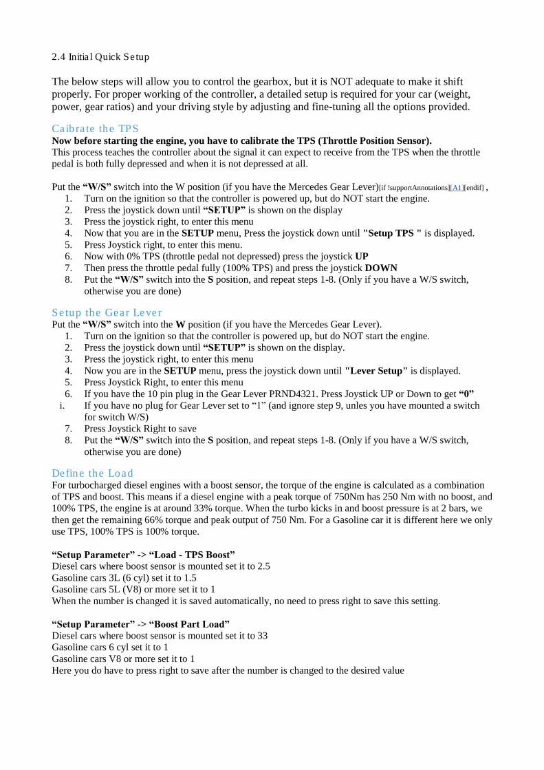
Caibrate the TPS Now before starting the engine, you have to calibrate the TPS (Throttle Position Sensor). This process teaches the controller about the signal it can expect to receive from the TPS when the throttle
pedal is both fully depressed and when it is not depressed at all.
Put the “W/S” switch into the W position (if you have the Mercedes Gear Lever)[if !supportAnnotations][A1][endif] ,
1. Turn on the ignition so that the controller is powered up, but do NOT start the engine.
2. Press the joystick down until “SETUP” is shown on the display
3. Press the joystick right, to enter this menu
4. Now that you are in the SETUP menu, Press the joystick down until "Setup TPS " is displayed.
5. Press Joystick right, to enter this menu.
6. Now with 0% TPS (throttle pedal not depressed) press the joystick UP
7. Then press the throttle pedal fully (100% TPS) and press the joystick DOWN
8. Put the “W/S” switch into the S position, and repeat steps 1-8. (Only if you have a W/S switch,
otherwise you are done)
Setup the Gear Lever Put the “W/S” switch into the W position (if you have the Mercedes Gear Lever).
1. Turn on the ignition so that the controller is powered up, but do NOT start the engine.
2. Press the joystick down until “SETUP” is shown on the display.
3. Press the joystick right, to enter this menu
4. Now you are in the SETUP menu, press the joystick down until "Lever Setup" is displayed.
5. Press Joystick Right, to enter this menu
6. If you have the 10 pin plug in the Gear Lever PRND4321. Press Joystick UP or Down to get “0”
i. If you have no plug for Gear Lever set to “1” (and ignore step 9, unles you have mounted a switch
for switch W/S)
7. Press Joystick Right to save
8. Put the “W/S” switch into the S position, and repeat steps 1-8. (Only if you have a W/S switch,
otherwise you are done)
Define the Load For turbocharged diesel engines with a boost sensor, the torque of the engine is calculated as a combination
of TPS and boost. This means if a diesel engine with a peak torque of 750Nm has 250 Nm with no boost, and
100% TPS, the engine is at around 33% torque. When the turbo kicks in and boost pressure is at 2 bars, we
then get the remaining 66% torque and peak output of 750 Nm. For a Gasoline car it is different here we only
use TPS, 100% TPS is 100% torque.
“Setup Parameter” -> “Load - TPS Boost” Diesel cars where boost sensor is mounted set it to 2.5
Gasoline cars 3L (6 cyl) set it to 1.5
Gasoline cars 5L (V8) or more set it to 1
When the number is changed it is saved automatically, no need to press right to save this setting.
“Setup Parameter” -> “Boost Part Load” Diesel cars where boost sensor is mounted set it to 33
Gasoline cars 6 cyl set it to 1
Gasoline cars V8 or more set it to 1
Here you do have to press right to save after the number is changed to the desired value
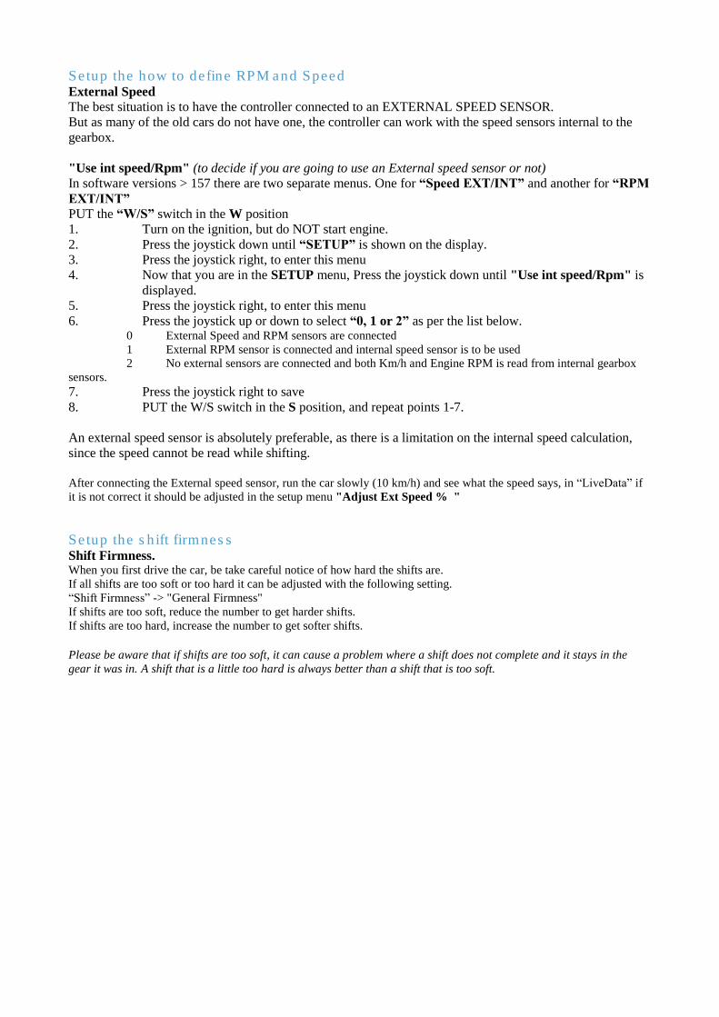
Setup the how to define RPM and Speed External Speed
The best situation is to have the controller connected to an EXTERNAL SPEED SENSOR.
But as many of the old cars do not have one, the controller can work with the speed sensors internal to the
gearbox.
"Use int speed/Rpm" (to decide if you are going to use an External speed sensor or not)
In software versions > 157 there are two separate menus. One for “Speed EXT/INT” and another for “RPM
EXT/INT” PUT the “W/S” switch in the W position
1. Turn on the ignition, but do NOT start engine.
2. Press the joystick down until “SETUP” is shown on the display.
3. Press the joystick right, to enter this menu
4. Now that you are in the SETUP menu, Press the joystick down until "Use int speed/Rpm" is
displayed.
5. Press the joystick right, to enter this menu
6. Press the joystick up or down to select “0, 1 or 2” as per the list below. 0 External Speed and RPM sensors are connected 1 External RPM sensor is connected and internal speed sensor is to be used 2 No external sensors are connected and both Km/h and Engine RPM is read from internal gearbox
sensors. 7. Press the joystick right to save
8. PUT the W/S switch in the S position, and repeat points 1-7.
An external speed sensor is absolutely preferable, as there is a limitation on the internal speed calculation,
since the speed cannot be read while shifting.
After connecting the External speed sensor, run the car slowly (10 km/h) and see what the speed says, in “LiveData” if
it is not correct it should be adjusted in the setup menu "Adjust Ext Speed % "
Setup the shift firmness Shift Firmness. When you first drive the car, be take careful notice of how hard the shifts are. If all shifts are too soft or too hard it can be adjusted with the following setting. “Shift Firmness” -> "General Firmness" If shifts are too soft, reduce the number to get harder shifts. If shifts are too hard, increase the number to get softer shifts. Please be aware that if shifts are too soft, it can cause a problem where a shift does not complete and it stays in the
gear it was in. A shift that is a little too hard is always better than a shift that is too soft.
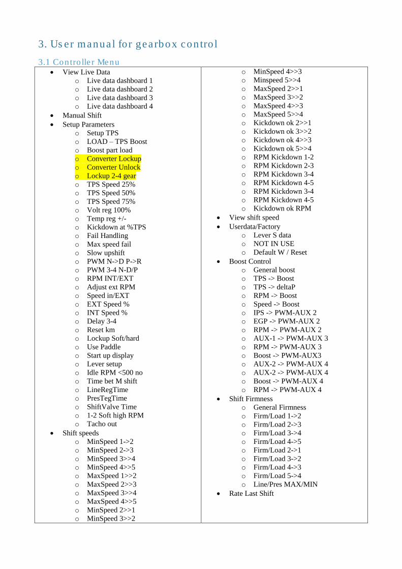
3. User manual for gearbox control
3.1 Controller Menu • View Live Data
o Live data dashboard 1
o Live data dashboard 2
o Live data dashboard 3
o Live data dashboard 4
• Manual Shift
• Setup Parameters
o Setup TPS
o LOAD – TPS Boost
o Boost part load
o Converter Lockup
o Converter Unlock
o Lockup 2-4 gear
o TPS Speed 25%
o TPS Speed 50%
o TPS Speed 75%
o Volt reg 100%
o Temp reg +/-
o Kickdown at %TPS
o Fail Handling
o Max speed fail
o Slow upshift
o PWM N->D P->R
o PWM 3-4 N-D/P
o RPM INT/EXT
o Adjust ext RPM
o Speed in/EXT
o EXT Speed %
o INT Speed %
o Delay 3-4
o Reset km
o Lockup Soft/hard
o Use Paddle
o Start up display
o Lever setup
o Idle RPM <500 no
o Time bet M shift
o LineRegTime
o PresTegTime
o ShiftValve Time
o 1-2 Soft high RPM
o Tacho out
• Shift speeds
o MinSpeed 1->2
o MinSpeed 2->3
o MinSpeed 3>>4
o MinSpeed 4>>5
o MaxSpeed 1>>2
o MaxSpeed 2>>3
o MaxSpeed 3>>4
o MaxSpeed 4>>5
o MinSpeed 2>>1
o MinSpeed 3>>2
o MinSpeed 4>>3
o Minspeed 5>>4
o MaxSpeed 2>>1
o MaxSpeed 3>>2
o MaxSpeed 4>>3
o MaxSpeed 5>>4
o Kickdown ok 2>>1
o Kickdown ok 3>>2
o Kickdown ok 4>>3
o Kickdown ok 5>>4
o RPM Kickdown 1-2
o RPM Kickdown 2-3
o RPM Kickdown 3-4
o RPM Kickdown 4-5
o RPM Kickdown 3-4
o RPM Kickdown 4-5
o Kickdown ok RPM
• View shift speed
• Userdata/Factory
o Lever S data
o NOT IN USE
o Default W / Reset
• Boost Control
o General boost
o TPS -> Boost
o TPS -> deltaP
o RPM -> Boost
o Speed -> Boost
o IPS -> PWM-AUX 2
o EGP -> PWM-AUX 2
o RPM -> PWM-AUX 2
o AUX-1 -> PWM-AUX 3
o RPM -> PWM-AUX 3
o Boost -> PWM-AUX3
o AUX-2 -> PWM-AUX 4
o AUX-2 -> PWM-AUX 4
o Boost -> PWM-AUX 4
o RPM -> PWM-AUX 4
• Shift Firmness
o General Firmness
o Firm/Load 1->2
o Firm/Load 2->3
o Firm/Load 3->4
o Firm/Load 4->5
o Firm/Load 2->1
o Firm/Load 3->2
o Firm/Load 4->3
o Firm/Load 5->4
o Line/Pres MAX/MIN
• Rate Last Shift
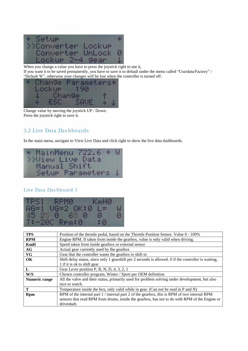
When you change a value you have to press the joystick right to use it, If you want it to be saved permanently, you have to save it to default under the menu called “Userdata/Factory” /
“Default W”, otherwise your changes will be lost when the controller is turned off.
Change value by moving the joystick UP / Down. Press the joystick right to save it.
3.2 Live Data Dashboards
In the main menu, navigate to View Live Data and click right to show the live data dashboards.
Live Data Dashboard 1
TPS Position of the throttle pedal, based on the Throttle Position Sensor. Value 0 - 100%
RPM Engine RPM. If taken from inside the gearbox, value is only valid when driving.
KmH Speed taken from inside gearbox or external sensor
AG Actual gear currently used by the gearbox
VG Gear that the controller wants the gearbox to shift to
OK Shift delay status, since only 1 gearshift per 2 seconds is allowed. 0 if the controller is waiting,
1 if it is ok to shift gear
L Gear Lever position P, R, N, D, 4, 3, 2, 1
W/S Chosen controller program, Winter / Sport per OEM definition
Numeric range All the valve and their status, primarily used for problem solving under development, but also
nice to watch.
T Temperature inside the box, only valid while in gear. (Can not be read in P and N)
Rpm RPM of the internal part 1 / internal part 2 of the gearbox, this is RPM of two internal RPM
sensors that read RPM from drums, inside the gearbox, has not to do with RPM of the Engine or
driveshaft.
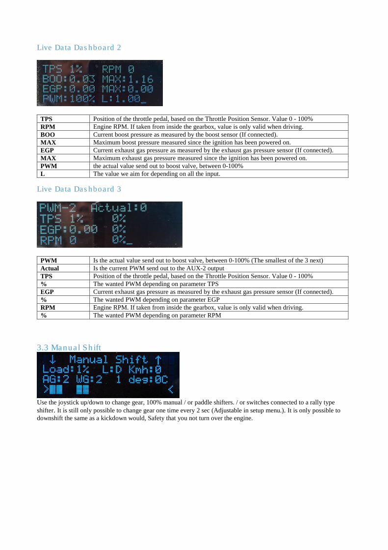
Live Data Dashboard 2
TPS Position of the throttle pedal, based on the Throttle Position Sensor. Value 0 - 100%
RPM Engine RPM. If taken from inside the gearbox, value is only valid when driving.
BOO Current boost pressure as measured by the boost sensor (If connected).
MAX Maximum boost pressure measured since the ignition has been powered on.
EGP Current exhaust gas pressure as measured by the exhaust gas pressure sensor (If connected).
MAX Maximum exhaust gas pressure measured since the ignition has been powered on.
PWM the actual value send out to boost valve, between 0-100%
L The value we aim for depending on all the input.
Live Data Dashboard 3
PWM Is the actual value send out to boost valve, between 0-100% (The smallest of the 3 next)
Actual Is the current PWM send out to the AUX-2 output
TPS Position of the throttle pedal, based on the Throttle Position Sensor. Value 0 - 100%
% The wanted PWM depending on parameter TPS
EGP Current exhaust gas pressure as measured by the exhaust gas pressure sensor (If connected).
% The wanted PWM depending on parameter EGP
RPM Engine RPM. If taken from inside the gearbox, value is only valid when driving.
% The wanted PWM depending on parameter RPM
3.3 Manual Shift
Use the joystick up/down to change gear, 100% manual / or paddle shifters. / or switches connected to a rally type
shifter. It is still only possible to change gear one time every 2 sec (Adjustable in setup menu.). It is only possible to
downshift the same as a kickdown would, Safety that you not turn over the engine.
3.4 Setup Parameters
Setup TPS
Setup TPS allows you to calibrate the TPS (Throttle Position Sensor). This process teaches the controller
about the signal it can expect to receive from the TPS when the throttle pedal is both fully depressed and
when it is not depressed at all.
Put the “W/S” switch into the W position (if you have the Mercedes Gear Lever),
1. Turn on the ignition so that the controller is powered up, but do NOT start the engine.
2. Press the joystick down until “SETUP” is shown on the display
3. Press the joystick right, to enter this menu
4. Now that you are in the SETUP menu, Press the joystick down until "Setup TPS " is displayed.
5. Press Joystick right, to enter this menu.
6. Now with 0% TPS (throttle pedal not depressed) press the joystick UP
7. Then press the throttle pedal fully (100% TPS) and press the joystick DOWN
8. Put the “W/S” switch into the S position, and repeat steps 1-8. (Only if you have a W/S switch,
otherwise you are done)
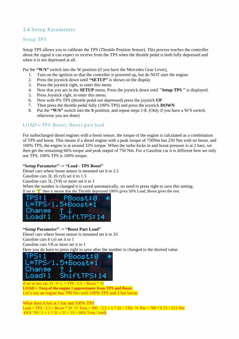
LOAD – TPS Boost; Boost part load For turbocharged diesel engines with a boost sensor, the torque of the engine is calculated as a combination
of TPS and boost. This means if a diesel engine with a peak torque of 750Nm has 250 Nm with no boost, and
100% TPS, the engine is at around 33% torque. When the turbo kicks in and boost pressure is at 2 bars, we
then get the remaining 66% torque and peak output of 750 Nm. For a Gasoline car it is different here we only
use TPS, 100% TPS is 100% torque.
“Setup Parameter” -> “Load - TPS Boost” Diesel cars where boost sensor is mounted set it to 2.5
Gasoline cars 3L (6 cyl) set it to 1.5
Gasoline cars 5L (V8) or more set it to 1
When the number is changed it is saved automatically, no need to press right to save this setting. If set to “2” then it means that the Throttle depressed 100% gives 50% Load, Boost gives the rest.
“Setup Parameter” -> “Boost Part Load” Diesel cars where boost sensor is mounted set it to 33
Gasoline cars 6 cyl set it to 1
Gasoline cars V8 or more set it to 1
Here you do have to press right to save after the number is changed to the desired value
If set to lets say 33 L = TPS / 2.5 + Boost * 33 LOAD = Torq of the engine I approximate from TPS and Boost.
Let’s say an engine has 700 Nm with 100% TPS and 2 bar boost.
What does it has at 1 bar and 100% TPS Load = TPS / 2.5 + Boost * 33 Torq = 100 / 2.5 + 1 * 33 = 73% Nm = 700 * 0.73 = 511 Nm EKS “50 / 2 + 1 * 33 = 25 + 33 = 68% Torq / load}
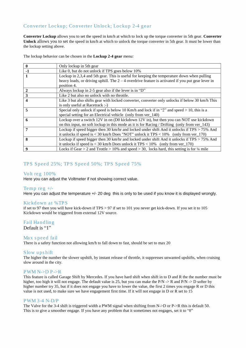
Converter Lockup; Converter Unlock; Lockup 2-4 gear Converter Lockup allows you to set the speed in km/h at which to lock up the torque converter in 5th gear. Converter
Unlock allows you to set the speed in km/h at which to unlock the torque converter in 5th gear. It must be lower than
the lockup setting above. The lockup behavior can be chosen in the Lockup 2-4 gear menu:
0 Only lockup in 5th gear -1 Like 0, but do not unlock if TPS goes below 10%
1 Lockup in 2,3,4 and 5th gear. This is useful for keeping the temperature down when pulling
heavy loads, or driving uphill. The 2 – 4 overdrive feature is activated if you put gear lever in
position 4.
2 Always lockup in 2-5 gear also if the lever is in “D”
3 Like 2 but also no unlock with no throttle. 4 Like 3 but also shifts gear with locked converter, converter only unlocks if below 30 km/h This
is only useful at Racetrack :-)
5 Special only unlock if speed is below 10 Km/h and lock if in “2” and speed > 10, this is a
special setting for an Electrical vehicle (only from ver_140)
6 Lockup over a switch 12V in on (D0 kickdown 12V in), but then you can NOT use kickdown
on this input, no soft lockup in this mode as it is for Racing / Drifting (only from ver_143) 7 Lockup if speed bigger then 30 km/hr and locked under shift And it unlocks if TPS > 75% And
it unlocks if speed is < 30 km/h Does "NOT" unlock it TPS < 10% (only from ver_170)
8 Lockup if speed bigger then 30 km/hr and locked under shift And it unlocks if TPS > 75% And
it unlocks if speed is < 30 km/h Does unlock it TPS < 10% (only from ver_170)
9 Locks if Gear > 2 and Trottle > 10% and speed > 30, locks hard, this setting is for ¼ mile
TPS Speed 25%; TPS Speed 50%; TPS Speed 75%
Volt reg 100% Here you can adjust the Voltmeter if not showing correct value.
Temp reg +/- Here you can adjust the temperature +/- 20 deg this is only to be used if you know it is displayed wrongly.
Kickdown at %TPS if set to 97 then you will have kick-down if TPS > 97 if set to 101 you never get kick-down. If you set it to 105
Kickdown would be triggered from external 12V source.
Fail Handling Default is “1”
Max speed fail There is a safety function not allowing km/h to fall down to fast, should be set to max 20
Slow upshift The higher the number the slower upshift, by instant release of throttle, it suppresses unwanted upshifts, when cruising
slow around in the city.
PWM N->D P->R This feature is called Garage Shift by Mercedes. If you have hard shift when shift in to D and R the the number must be
higher, too high it will not engage. The default value is 25, but you can make the P/N -> R and P/N -> D softer by
higher number try 35, but if it does not engage you have to lower the value, the first 2 times you engage R or D this
value is not used, to make sure we have engagement first time. If it will not engage in D or R set to 15
PWM 3-4 N-D/P The Valve for the 3-4 shift is triggered width a PWM signal when shifting from N->D or P->R this is default 50. This is to give a smoother engage. If you have any problem that it sometimes not engages, set it to “0”
RPM INT/EXT; Adjust ext RPM Use internal RPM from gearbox, or external RPM. The internal RPM will always show 0 if car is stationary, and engine
is running as the converter is slipping, this is normal.
The external RPM signal can be adjusted if the value is not showing the correct RPM, only use if you use external
engine RPM. The default value in the Adjust ext RPM is 36. If RPM is too high, lower this number. In Software > 157 there is two separate menu One for
Speed in/EXT; EXT Speed %; INT Speed % The best situation is to have the controller connected to an external speed signal. Since many older cars do
not have one, the controller can work with the speed sensors internal to the gearbox as well. This allows the
car to drive, but has a significant downside as well. During shift, there is a short timeframe where the speed
can not be calculated. In case of a significant speed increase (powerful engine) or speed decrease (emergency
brake during shift), the speed signal can fluctuate too much and the controller will stop shifting to prevent
potential damage.
Use internal/external speed (to decide if you are going to use an External speed sensor or not)
PUT the “W/S” switch in the W position
1. Turn on the ignition, but do NOT start engine.
2. Press the joystick down until “SETUP” is shown on the display.
3. Press the joystick right, to enter this menu
4. Now that you are in the SETUP menu, Press the joystick down until "Use int
speed/Rpm" is displayed.
5. Press the joystick right, to enter this menu
6. Press the joystick up or down to select “0, 1 or 2” as per the list below.
7. Press the joystick right to save
8. PUT the W/S switch in the S position, and repeat points 1-7.
After connecting the choosing the way to calculate speed, the speed needs to be checked for accuracy. To do
so, run the car slowly (10 km/h) and see what the speed says in “LiveData”. If it is not correct it should be
adjusted in the setup menu "Adjust Ext Speed %" or INT Speed %, depending if you are using an internal or
an external speed signal.
Delay 3-4 The 722.6 gearbox has a delay when shifting from 3 -> 4. This delay can be an issue with high powered cars
or when towing. This option allows you to adjust the shifting behavior to match the health of your gearbox
and the power / usage of your car. Only if you have problem with slip in 3-4, start with 5 and 1 up at the
time, until it goes away, do not go over 15 since then you have a bad box.
If you set it to exact “-1” the 3 -> 4 shift only happens if TPS is below 45% that is great as you let of the TPS
when you want the shift, and it shift smooth.
If you set it to “-1 to -9” the 3 -> 4 shift only happens if TPS is below -1 = 10% and -9 = 90% that is great as
you let of the TPS when you want the shift, and it shift smooth.
Reset km Press Right This will reset to Total Km to “0” Km
Press Up this will add 1000 Km at each press
Press Down This will subtract 100 Km, that mean you can adjust to a precision of 100 km.
Lockup Soft/hard "Lockup Soft / Hard"
Use Paddle
Start up display
Lever setup
Put the “W/S” switch into the W position (if you have the Mercedes Gear Lever).
1. Turn on the ignition so that the controller is powered up, but do NOT start the engine.
2. Press the joystick down until “SETUP” is shown on the display.
3. Press the joystick right, to enter this menu
4. Now you are in the SETUP menu, press the joystick down until "Lever Setup" is displayed.
5. Press Joystick Right, to enter this menu
6. If you have the 10 pin plug in the Gear Lever PRND4321. Press Joystick UP or Down to get “0”
i. If you have no plug for Gear Lever set to “1” (and ignore step 9, unles you have mounted a switch
for switch W/S)
7. Press Joystick Right to save
8. Put the “W/S” switch into the S position, and repeat steps 1-8. (Only if you have a W/S switch,
otherwise you are done)
Idle RPM <500 no Only used in some cases, if components is mounted. and only if there is external RPM-signal as the calculated RPM
signal will always be 0 at stationary car. it has to be set higher then 500 RPM, to get an output. From ver 123 If set to exatly “510” something special will happen it will adjust idle to 800 when Gearoil temp is below 45 deg, and to
650 when hotter.
Time bet M shift
LineRegTime
PresTegTime
ShiftValve Time
1-2 Soft high RPM
Tacho out
"Temp Line -20deg "
Adjust the line pressure at cold "Temp Line 120deg "
Adjust the line pressure at Hot "Temp Pres -20deg "
Adjust the shift pressure at cold "Temp Pres 120deg "
Adjust the shift pressure at hot "Use Paddle shift " Use paddles on analog 9, 0 = disable 1 = Read the value for testing 2 = Read the value and activates the horn output 3 = Paddle shift activated 4 = Paddle shift activated, and if in main menu, and paddle is pressed it shift to manual instant, and goes back to auto if
you drive very slow in high gear, (only in SW 95 or higher) "Time bet shift " = time between shifts Used to change the minimum time between shift, if set to 1000 mS then you can shift from 1 to 2 then you have to wait
1 sec to shift 2 to 3, This time is also used in automatic mode but here is added 500 mS this means that when the time is set to 1500 mS
“Standard ” it is 2000 mS in automatic. "0 point boost " Moved to Boost menu where the boost sensor has 0 bar on the 0 - 1024 scale if it is a 3 bar sensor it would propably hav a range from -1,5 bar
to 3,5 bar 0 - 5 v and the value here should propably be set to 300.it can be tested on the 2. live data page,
where you press right on the live data, you can press right to get the second page. you should adjust until
you just see a little boost when engine not running. "Max boost at 5v " Moved to Boost menu This is the max boost your sensor can handle. A 3 bar boost sensor has 3 bar at 4,5 volt, 3,5 bar at 5 volt, this value has
to be set to 350 “mBar at 5 volt” “Show on Display at Startup”
in live data, you can change what to display on line 3 0 = Normal, just main menu
1 = Boost menu, Live Data (This is if you just use the controller as Boost Controller. and want to have live data all the
time) 2 = Start up in Manual mode, (RACEMODE or if you just want Manual all the time.) 3 = Live Data
“VNT Boost/EGP” ( Moved to Boost menu)
Boost controller is used 1, 2, 3, 4 is for VNT Turbos 4 different algorithm to adjust boost 5 is for Normal Turbo 6 is for Normal Turbo more aggressive limit 7 is for Normal Turbo even more aggressive limit 8,9,..................... 20 extreme aggressive limit.
“Lever setup” 0 = MB standard lever 1 = No lever, N, P and R & D can be detected but not 4-3-2-1 2 = Special For a special gearbox having a 120 OHM output when in “R” (gives reverseligth output on
AUX-3)
“Limit Engine Power under shift” (Not in this setup menu, but i think you would try to find it here) Under “GeneralBoost” goto Use PWM - AUX-4,
The following happens for different value
2, you get instant 200 mS 100% PWM
3, you get instant 300 mS 100% PWM
12 you get 100 mS delayed 200 mS 100% PWM (1 is 100mS delay the 2 is 200-100 = 100 mS
signal) 25 you get 200 mS delayed 500 mS 100% PWM (2 is 200mS delay the 5 is 500-200 = 300 mS
signal) By the way Engine limit only works at TPS > 20% (prevent stop engine at low RPM) If you want to Limit Power on Mercedes Gasolin car, where before a 722.3 was From Switch S65 on Gearbox width 1K Ohm resistor Pin 1 and Pin 2 width a relay
3.4 Shift Speeds
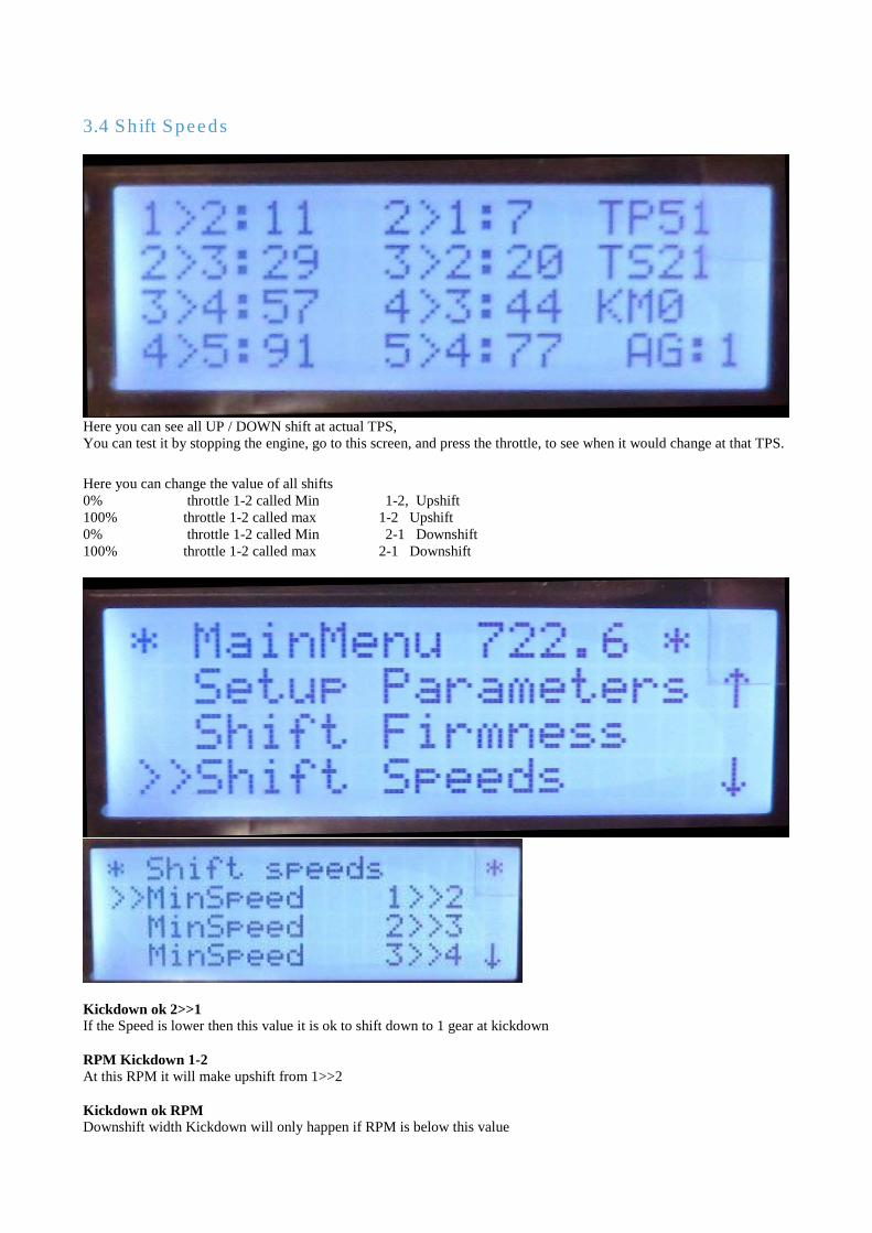
Here you can see all UP / DOWN shift at actual TPS, You can test it by stopping the engine, go to this screen, and press the throttle, to see when it would change at that TPS.
Here you can change the value of all shifts 0% throttle 1-2 called Min 1-2, Upshift 100% throttle 1-2 called max 1-2 Upshift 0% throttle 1-2 called Min 2-1 Downshift 100% throttle 1-2 called max 2-1 Downshift
Kickdown ok 2>>1 If the Speed is lower then this value it is ok to shift down to 1 gear at kickdown RPM Kickdown 1-2 At this RPM it will make upshift from 1>>2 Kickdown ok RPM Downshift width Kickdown will only happen if RPM is below this value
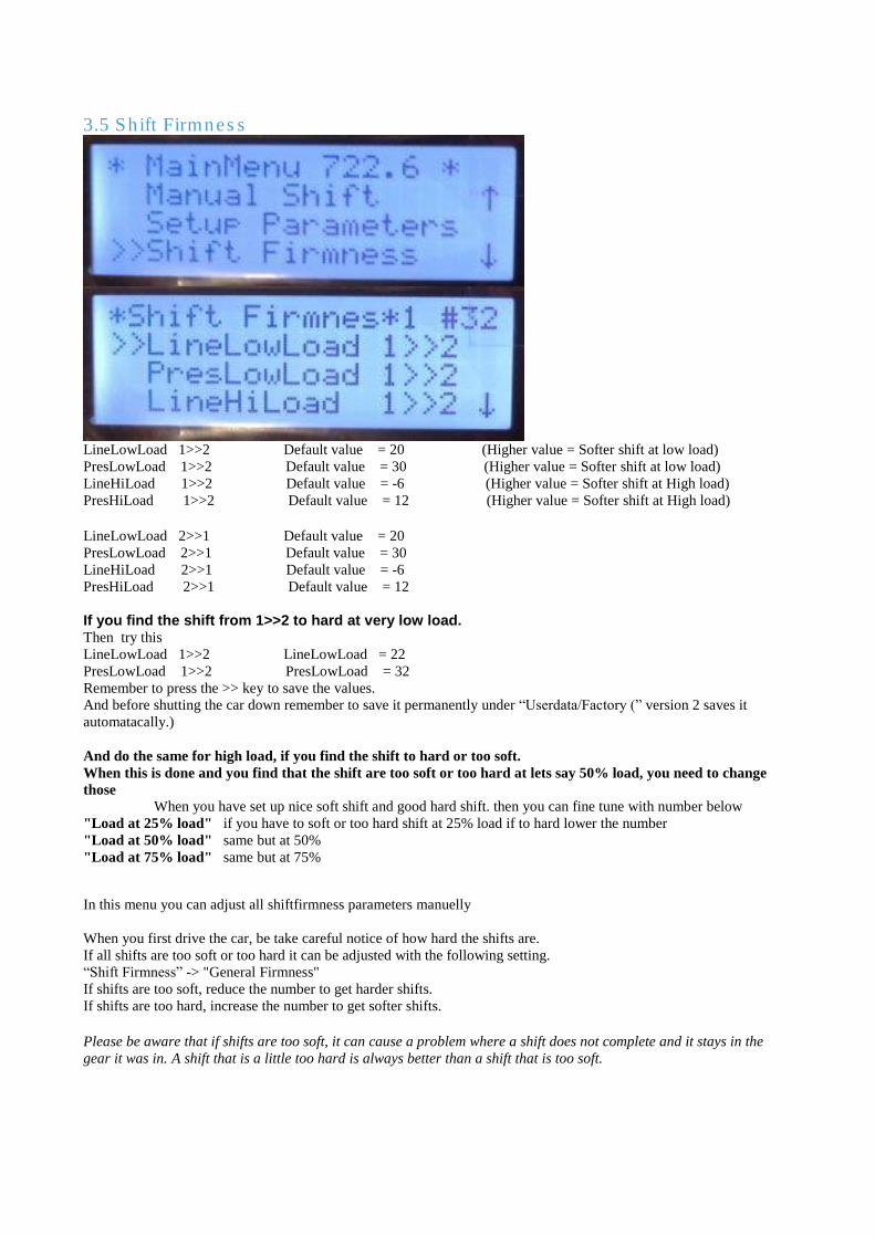
3.5 Shift Firmness
LineLowLoad 1>>2 Default value = 20 (Higher value = Softer shift at low load) PresLowLoad 1>>2 Default value = 30 (Higher value = Softer shift at low load) LineHiLoad 1>>2 Default value = -6 (Higher value = Softer shift at High load) PresHiLoad 1>>2 Default value = 12 (Higher value = Softer shift at High load) LineLowLoad 2>>1 Default value = 20 PresLowLoad 2>>1 Default value = 30 LineHiLoad 2>>1 Default value = -6 PresHiLoad 2>>1 Default value = 12 If you find the shift from 1>>2 to hard at very low load. Then try this LineLowLoad 1>>2 LineLowLoad = 22 PresLowLoad 1>>2 PresLowLoad = 32 Remember to press the >> key to save the values. And before shutting the car down remember to save it permanently under “Userdata/Factory (” version 2 saves it
automatacally.) And do the same for high load, if you find the shift to hard or too soft. When this is done and you find that the shift are too soft or too hard at lets say 50% load, you need to change
those When you have set up nice soft shift and good hard shift. then you can fine tune with number below
"Load at 25% load" if you have to soft or too hard shift at 25% load if to hard lower the number "Load at 50% load" same but at 50% "Load at 75% load" same but at 75%
In this menu you can adjust all shiftfirmness parameters manuelly
When you first drive the car, be take careful notice of how hard the shifts are. If all shifts are too soft or too hard it can be adjusted with the following setting. “Shift Firmness” -> "General Firmness" If shifts are too soft, reduce the number to get harder shifts. If shifts are too hard, increase the number to get softer shifts. Please be aware that if shifts are too soft, it can cause a problem where a shift does not complete and it stays in the
gear it was in. A shift that is a little too hard is always better than a shift that is too soft.
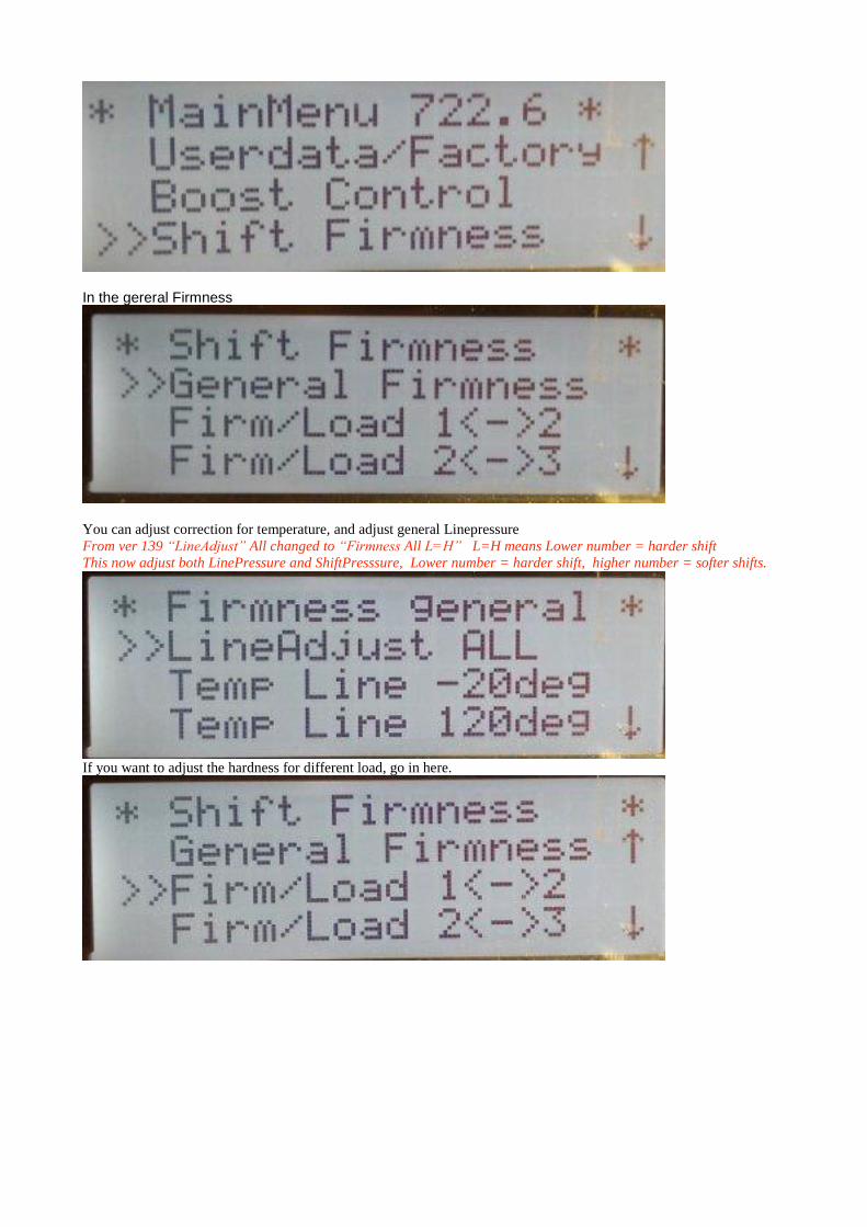
In the gereral Firmness
You can adjust correction for temperature, and adjust general Linepressure From ver 139 “LineAdjust” All changed to “Firmness All L=H” L=H means Lower number = harder shift This now adjust both LinePressure and ShiftPresssure, Lower number = harder shift, higher number = softer shifts.
If you want to adjust the hardness for different load, go in here.
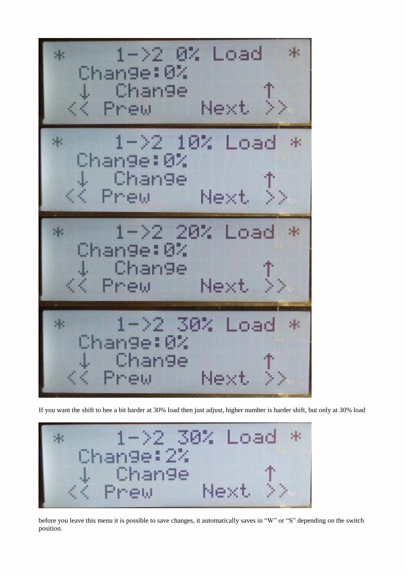
If you want the shift to bee a bit harder at 30% load then just adjust, higher number is harder shift, but only at 30% load
before you leave this menu it is possible to save changes, it automatically saves in “W” or “S” depending on the switch
position.
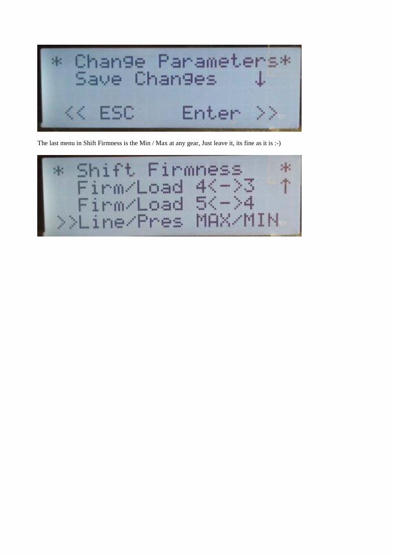
The last menu in Shift Firmness is the Min / Max at any gear, Just leave it, its fine as it is :-)
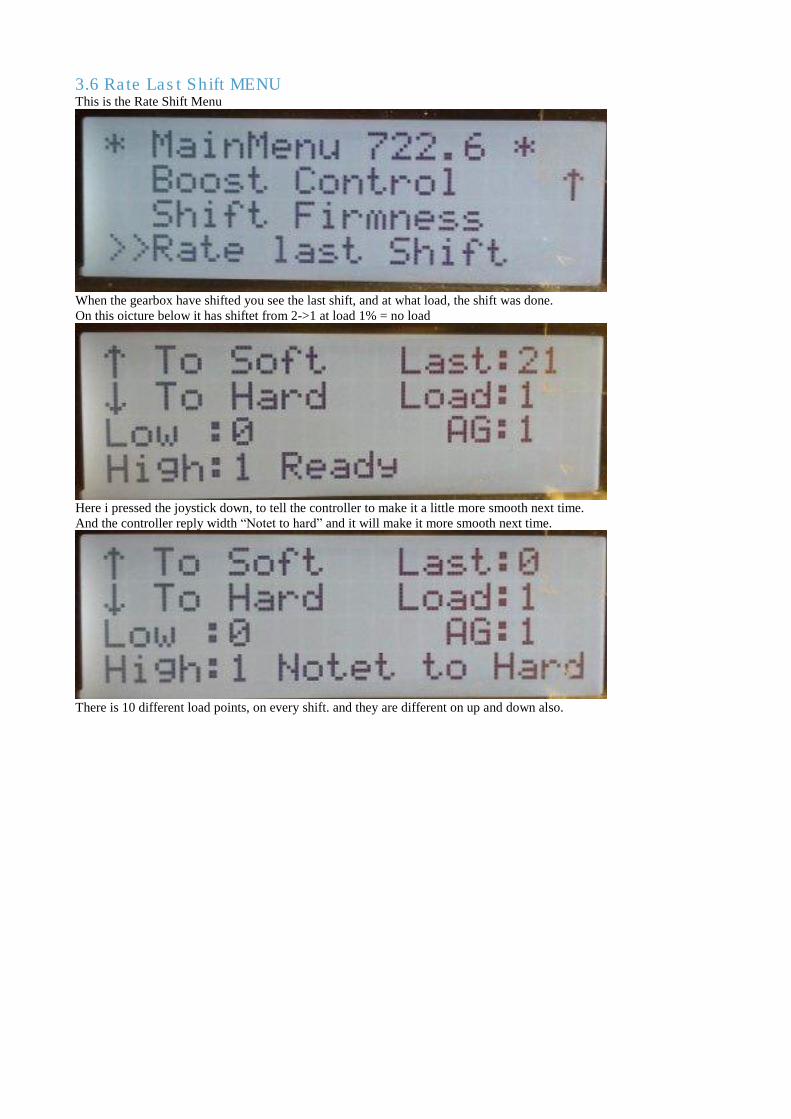
3.6 Rate Last Shift MENU This is the Rate Shift Menu
When the gearbox have shifted you see the last shift, and at what load, the shift was done. On this oicture below it has shiftet from 2->1 at load 1% = no load
Here i pressed the joystick down, to tell the controller to make it a little more smooth next time. And the controller reply width “Notet to hard” and it will make it more smooth next time.
There is 10 different load points, on every shift. and they are different on up and down also.
4. User manual for boost control
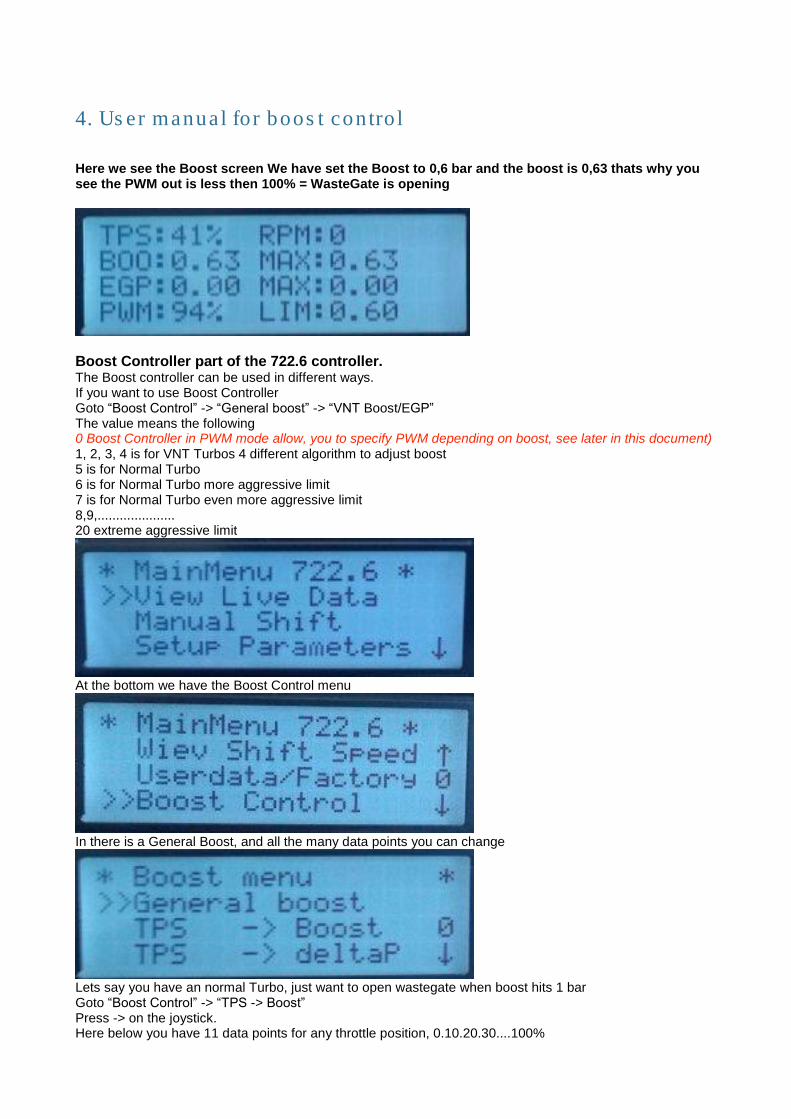
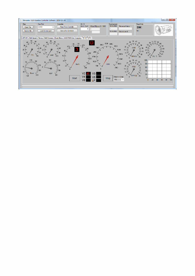
Here we see the Boost screen We have set the Boost to 0,6 bar and the boost is 0,63 thats why you see the PWM out is less then 100% = WasteGate is opening
Boost Controller part of the 722.6 controller. The Boost controller can be used in different ways. If you want to use Boost Controller Goto “Boost Control” -> “General boost” -> “VNT Boost/EGP” The value means the following 0 Boost Controller in PWM mode allow, you to specify PWM depending on boost, see later in this document) 1, 2, 3, 4 is for VNT Turbos 4 different algorithm to adjust boost 5 is for Normal Turbo 6 is for Normal Turbo more aggressive limit 7 is for Normal Turbo even more aggressive limit 8,9,..................... 20 extreme aggressive limit
At the bottom we have the Boost Control menu
In there is a General Boost, and all the many data points you can change
Lets say you have an normal Turbo, just want to open wastegate when boost hits 1 bar Goto “Boost Control” -> “TPS -> Boost” Press -> on the joystick. Here below you have 11 data points for any throttle position, 0.10.20.30....100%
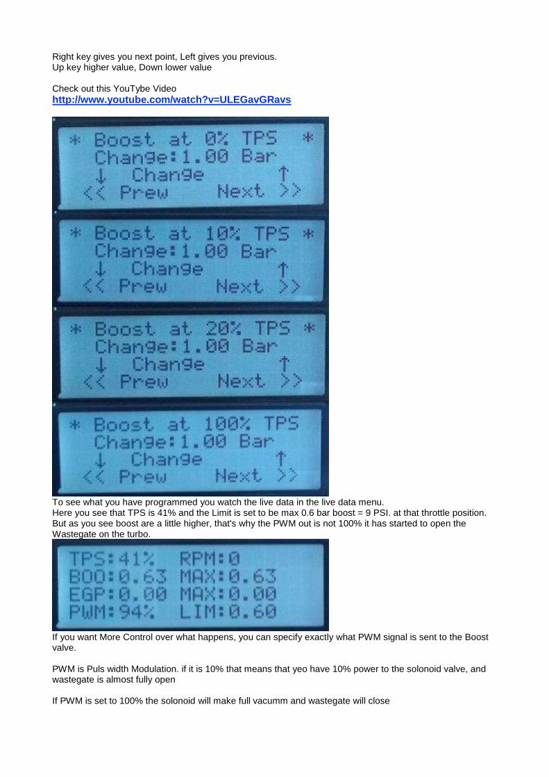
Right key gives you next point, Left gives you previous. Up key higher value, Down lower value Check out this YouTybe Video http://www.youtube.com/watch?v=ULEGavGRavs
To see what you have programmed you watch the live data in the live data menu. Here you see that TPS is 41% and the Limit is set to be max 0.6 bar boost = 9 PSI. at that throttle position. But as you see boost are a little higher, that's why the PWM out is not 100% it has started to open the Wastegate on the turbo.
If you want More Control over what happens, you can specify exactly what PWM signal is sent to the Boost valve. PWM is Puls width Modulation. if it is 10% that means that yeo have 10% power to the solonoid valve, and wastegate is almost fully open If PWM is set to 100% the solonoid will make full vacumm and wastegate will close
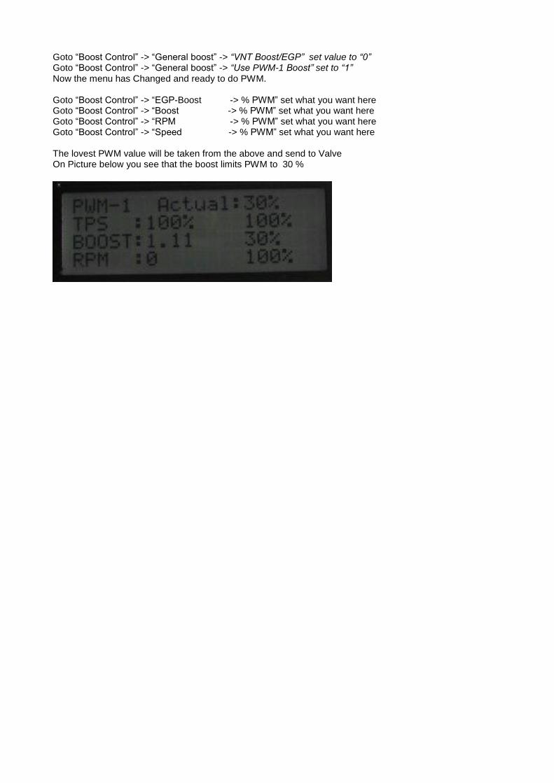
Goto “Boost Control” -> “General boost” -> “VNT Boost/EGP” set value to “0” Goto “Boost Control” -> “General boost” -> “Use PWM-1 Boost” set to “1” Now the menu has Changed and ready to do PWM. Goto “Boost Control” -> “EGP-Boost -> % PWM” set what you want here Goto “Boost Control” -> “Boost -> % PWM” set what you want here Goto “Boost Control” -> “RPM -> % PWM” set what you want here Goto “Boost Control” -> “Speed -> % PWM” set what you want here The lovest PWM value will be taken from the above and send to Valve On Picture below you see that the boost limits PWM to 30 %
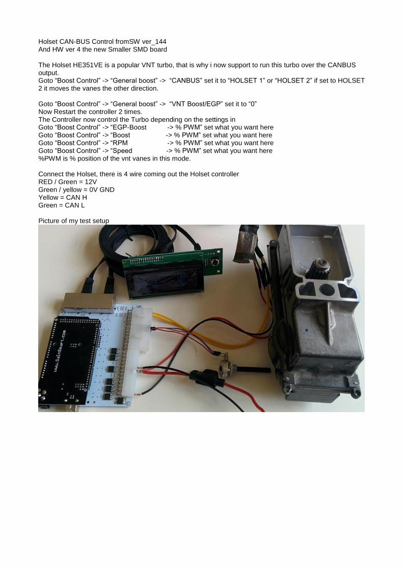
Holset CAN-BUS Control fromSW ver_144 And HW ver 4 the new Smaller SMD board The Holset HE351VE is a popular VNT turbo, that is why i now support to run this turbo over the CANBUS output. Goto “Boost Control” -> “General boost” -> “CANBUS” set it to “HOLSET 1” or “HOLSET 2” if set to HOLSET 2 it moves the vanes the other direction. Goto “Boost Control” -> “General boost” -> “VNT Boost/EGP” set it to “0” Now Restart the controller 2 times. The Controller now control the Turbo depending on the settings in Goto “Boost Control” -> “EGP-Boost -> % PWM” set what you want here Goto “Boost Control” -> “Boost -> % PWM” set what you want here Goto “Boost Control” -> “RPM -> % PWM” set what you want here Goto “Boost Control” -> “Speed -> % PWM” set what you want here %PWM is % position of the vnt vanes in this mode. Connect the Holset, there is 4 wire coming out the Holset controller RED / Green = 12V Green / yellow = 0V GND Yellow = CAN H Green = CAN L Picture of my test setup
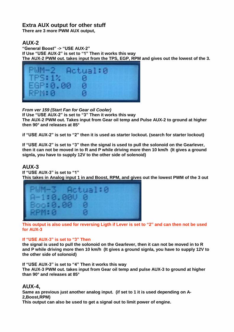
Extra AUX output for other stuff There are 3 more PWM AUX output,
AUX-2
“General Boost” -> “USE AUX-2” If Use “USE AUX-2” is set to “1” Then it works this way The AUX-2 PWM out. takes input from the TPS, EGP, RPM and gives out the lowest of the 3.
From ver 159 (Start Fan for Gear oil Cooler) If Use “USE AUX-2” is set to “3” Then it works this way The AUX-2 PWM out. Takes input from Gear oil temp and Pulse AUX-2 to ground at higher then 90° and releases at 85° if “USE AUX-2” is set to “2” then it is used as starter lockout. (search for starter lockout) If “USE AUX-2” is set to “3” then the signal is used to pull the solonoid on the Gearlever, then it can not be moved in to R and P while driving more then 10 km/h (It gives a ground signla, you have to supply 12V to the other side of solenoid)
AUX-3 If “USE AUX-3” is set to “1” This takes in Analog input 1 in and Boost, RPM, and gives out the lowest PWM of the 3 out
. This output is also used for reversing Ligth if Lever is set to “2” and can then not be used for AUX-3 If “USE AUX-3” is set to “3” Then the signal is used to pull the solonoid on the Gearlever, then it can not be moved in to R and P while driving more then 10 km/h (It gives a ground signla, you have to supply 12V to the other side of solonoid) If “USE AUX-3” is set to “4” Then it works this way The AUX-3 PWM out. takes input from Gear oil temp and pulse AUX-3 to ground at higher than 90° and releases at 85°
AUX-4, Same as previous just another analog input. (if set to 1 it is used depending on A-2,Boost,RPM) This output can also be used to get a signal out to limit power of engine.
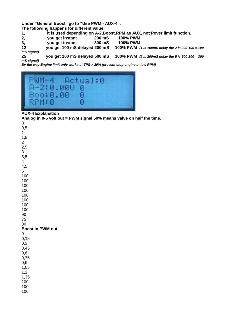
Under “General Boost” go to “Use PWM - AUX-4”, The following happens for different value 1, it is used depending on A-2,Boost,RPM as AUX, not Pover limit function. 2, you get instant 200 mS 100% PWM 3, you get instant 300 mS 100% PWM 12 you get 100 mS delayed 200 mS 100% PWM (1 is 100mS delay the 2 is 200-100 = 100
mS signal) 25 you get 200 mS delayed 500 mS 100% PWM (2 is 200mS delay the 5 is 500-200 = 300
mS signal) By the way Engine limit only works at TPS > 20% (prevent stop engine at low RPM)
AUX-4 Explanation Analog in 0-5 volt out = PWM signal 50% means valve on half the time. 0 0,5 1 1,5 2 2,5 3 3,5 4 4,5 5 100 100 100 100 100 100 100 100 90 75 30 Boost in PWM out 0 0,15 0.3 0,45 0,6 0,75 0,9 1,05 1,2 1,35 100 100 100
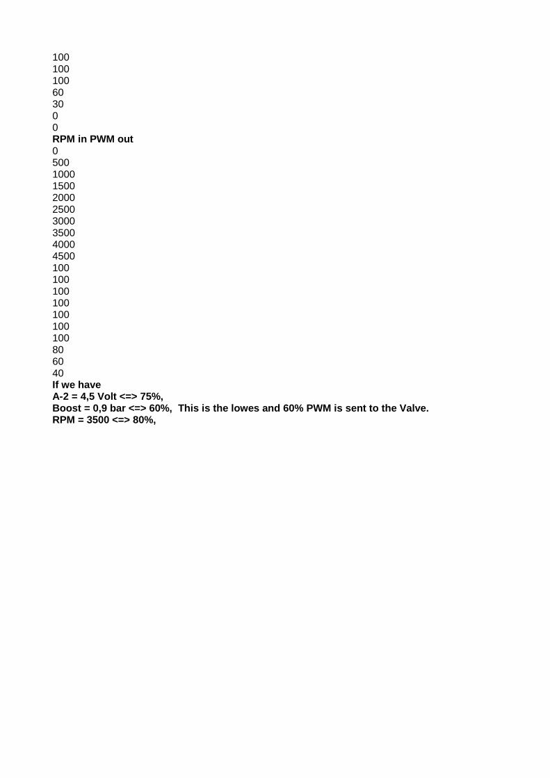
100 100 100 60 30 0 0 RPM in PWM out 0 500 1000 1500 2000 2500 3000 3500 4000 4500 100 100 100 100 100 100 100 80 60 40 If we have A-2 = 4,5 Volt <=> 75%, Boost = 0,9 bar <=> 60%, This is the lowes and 60% PWM is sent to the Valve. RPM = 3500 <=> 80%,
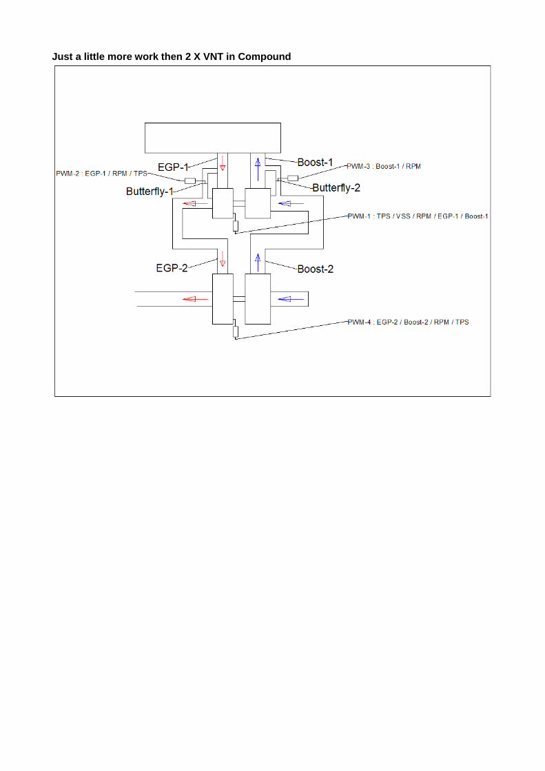
Just a little more work then 2 X VNT in Compound

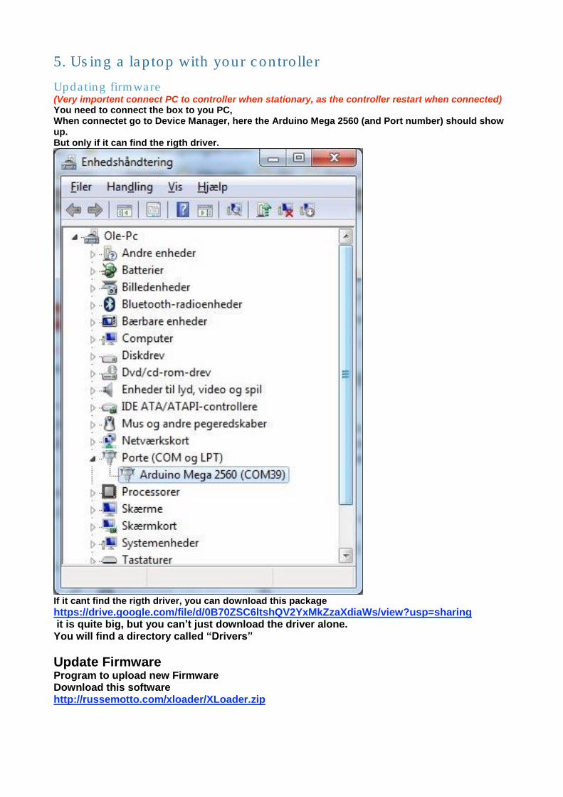
5. Using a laptop with your controller
Updating firmware (Very importent connect PC to controller when stationary, as the controller restart when connected) You need to connect the box to you PC, When connectet go to Device Manager, here the Arduino Mega 2560 (and Port number) should show up. But only if it can find the rigth driver.
If it cant find the rigth driver, you can download this package https://drive.google.com/file/d/0B70ZSC6ltshQV2YxMkZzaXdiaWs/view?usp=sharing it is quite big, but you can’t just download the driver alone. You will find a directory called “Drivers”
Update Firmware
Program to upload new Firmware Download this software http://russemotto.com/xloader/XLoader.zip
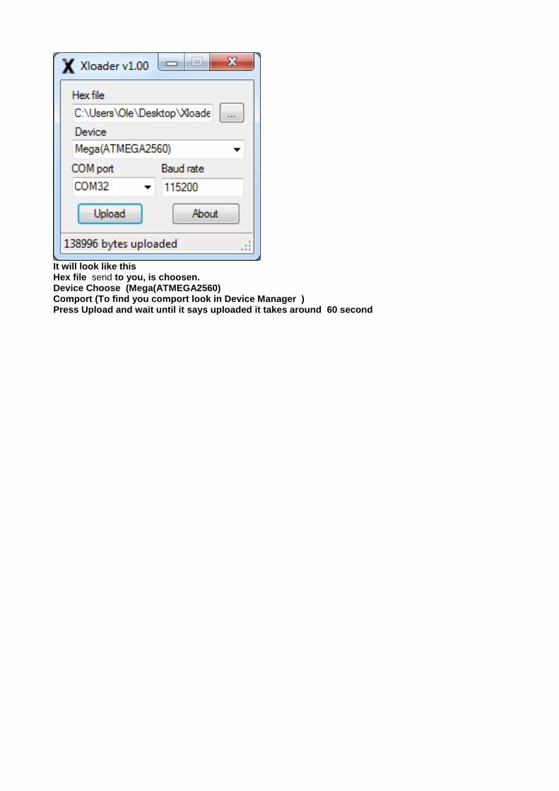
It will look like this Hex file send to you, is choosen. Device Choose (Mega(ATMEGA2560) Comport (To find you comport look in Device Manager ) Press Upload and wait until it says uploaded it takes around 60 second
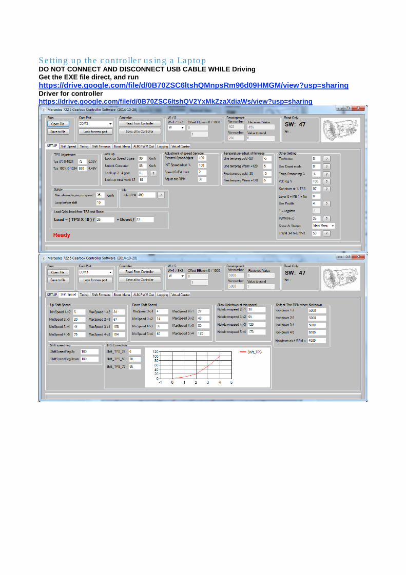
Setting up the controller using a Laptop DO NOT CONNECT AND DISCONNECT USB CABLE WHILE Driving Get the EXE file direct, and run https://drive.google.com/file/d/0B70ZSC6ltshQMnpsRm96d09HMGM/view?usp=sharing Driver for controller https://drive.google.com/file/d/0B70ZSC6ltshQV2YxMkZzaXdiaWs/view?usp=sharing
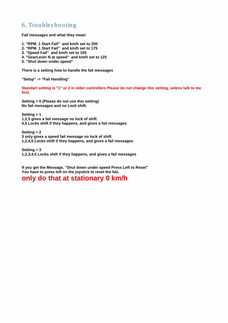
6. Troubleshooting Fail messages and what they mean 1. "RPM_1 Start Fail" and km/h set to 200 2. "RPM_1 Start Fail" and km/h set to 175 3. "Speed Fail" and km/h set to 150 4. "GearLever N at speed" and km/h set to 125 5. "Shut down under speed" There is a setting how to handle the fail messages "Setup" -> "Fail Handling" Standart setting is "1" or 2 in older controllers Please do not change this setting, unless talk to me first. Setting = 0 (Please do not use this setting) No fail messages and no Lock shift. Setting = 1 1,2,3 gives a fail message no lock of shift 4,5 Locks shift if they happens, and gives a fail messages Setting = 2 3 only gives a speed fail message no lock of shift 1,2,4,5 Locks shift if they happens, and gives a fail messages Setting = 3 1,2,3,4,5 Locks shift if they happens, and gives a fail messages If you get the Message, "Shut down under speed Press Left to Reset" You have to press left on the joystick to reset the fail,
only do that at stationary 0 km/h
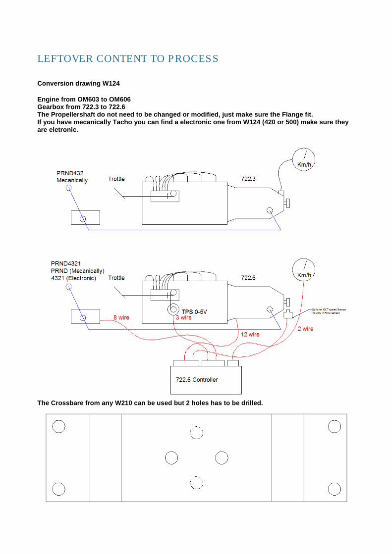
LEFTOVER CONTENT TO PROCESS Conversion drawing W124 Engine from OM603 to OM606 Gearbox from 722.3 to 722.6 The Propellershaft do not need to be changed or modified, just make sure the Flange fit. If you have mecanically Tacho you can find a electronic one from W124 (420 or 500) make sure they are eletronic.
The Crossbare from any W210 can be used but 2 holes has to be drilled.
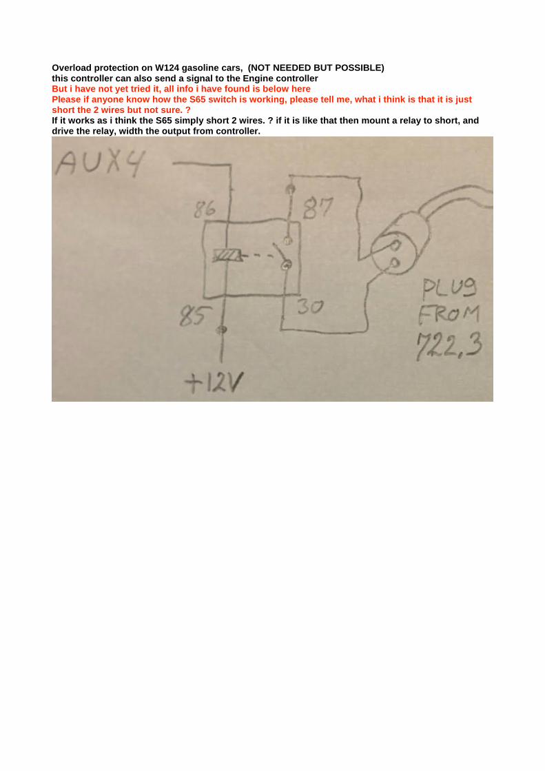
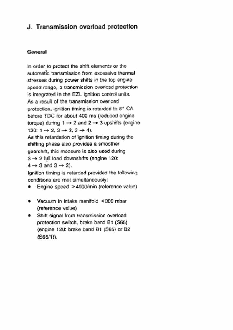
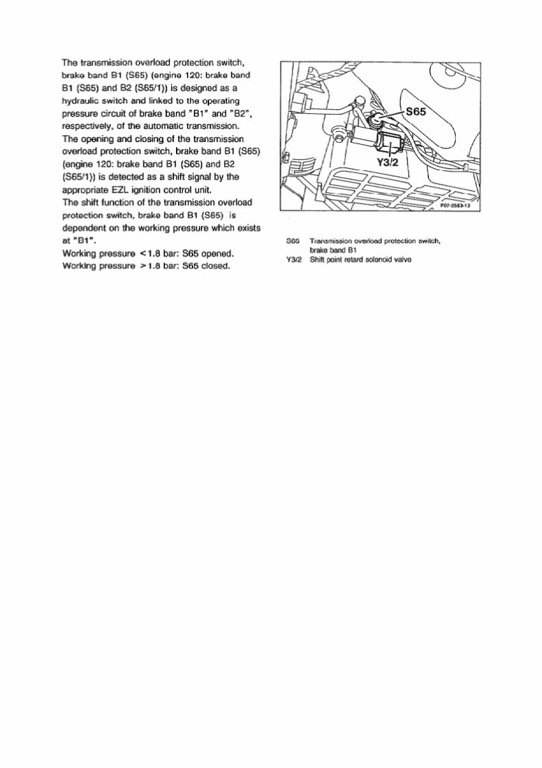
Overload protection on W124 gasoline cars, (NOT NEEDED BUT POSSIBLE) this controller can also send a signal to the Engine controller But i have not yet tried it, all info i have found is below here Please if anyone know how the S65 switch is working, please tell me, what i think is that it is just short the 2 wires but not sure. ? If it works as i think the S65 simply short 2 wires. ? if it is like that then mount a relay to short, and drive the relay, width the output from controller.
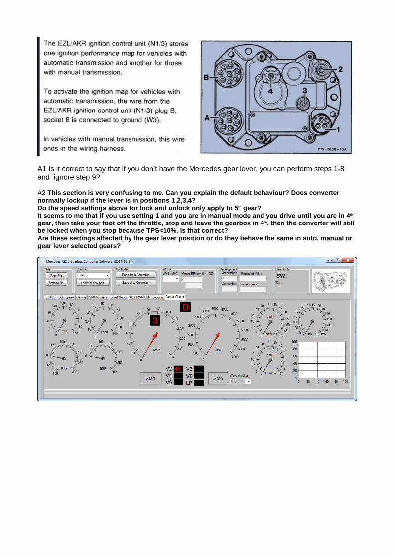
A1 Is it correct to say that if you don’t have the Mercedes gear lever, you can perform steps 1-8 and ignore step 9? A2 This section is very confusing to me. Can you explain the default behaviour? Does converter normally lockup if the lever is in positions 1,2,3,4? Do the speed settings above for lock and unlock only apply to 5th gear? It seems to me that if you use setting 1 and you are in manual mode and you drive until you are in 4th gear, then take your foot off the throttle, stop and leave the gearbox in 4th, then the converter will still be locked when you stop because TPS<10%. Is that correct? Are these settings affected by the gear lever position or do they behave the same in auto, manual or gear lever selected gears?

GearOil It is very important that the gear Oil level is correct in the 722.6 but if you don't have a dipstick here is how you can make you own. as the 722.6 newer has a dipstick from new. Mercedes Part number : 140589152100
http://autoimport.dk/mercedes_webcatalog/search/?q=KA-6953
http://mbspecialist.com/mercedes_webcatalog/search/?q=KA-6953&search-button.x=0&search-button.y=0
Here is a link to discussion of Oil Level http://www.benzworld.org/forums/w210-e-class/1565510-w210-homemade-dipstick-722-6-transmission-2.html

SpeedoMeter Great Link to keep speedo working on old cars from here http://www.peachparts.com/shopforum/diesel-discussion/308791-380sl-diesel-conversion-project-15.html FROM the link But I figured out how to move the internal VR trigger wheel to the driveshaft and keep the tailcone with the manual speedo on the 722.4. Here's a diagram of the strategy. (The full thread on this topic,
including images of the proof-of-concept test is here - Mechanical to Electronic Speedometer
Conversion )
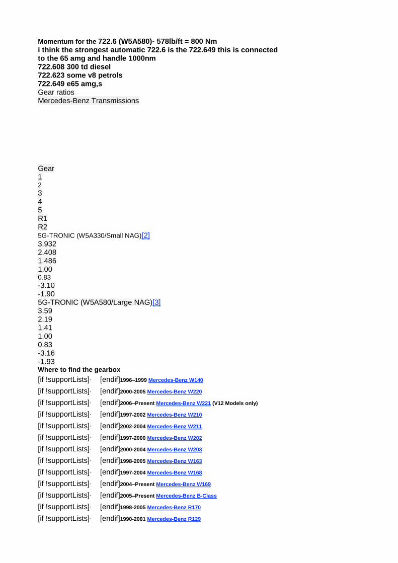
Momentum for the 722.6 (W5A580)- 578lb/ft = 800 Nm i think the strongest automatic 722.6 is the 722.649 this is connected to the 65 amg and handle 1000nm 722.608 300 td diesel 722.623 some v8 petrols 722.649 e65 amg,s Gear ratios Mercedes-Benz Transmissions
Gear 1 2 3 4 5 R1 R2 5G-TRONIC (W5A330/Small NAG)[2] 3.932 2.408 1.486 1.00 0.83 -3.10 -1.90 5G-TRONIC (W5A580/Large NAG)[3] 3.59 2.19 1.41 1.00 0.83 -3.16 -1.93 Where to find the gearbox
[if !supportLists]· [endif]1996–1999 Mercedes-Benz W140
[if !supportLists]· [endif]2000-2005 Mercedes-Benz W220
[if !supportLists]· [endif]2006–Present Mercedes-Benz W221 (V12 Models only)
[if !supportLists]· [endif]1997-2002 Mercedes-Benz W210
[if !supportLists]· [endif]2002-2004 Mercedes-Benz W211
[if !supportLists]· [endif]1997-2000 Mercedes-Benz W202
[if !supportLists]· [endif]2000-2004 Mercedes-Benz W203
[if !supportLists]· [endif]1998-2005 Mercedes-Benz W163
[if !supportLists]· [endif]1997-2004 Mercedes-Benz W168
[if !supportLists]· [endif]2004–Present Mercedes-Benz W169
[if !supportLists]· [endif]2005–Present Mercedes-Benz B-Class
[if !supportLists]· [endif]1998-2005 Mercedes-Benz R170
[if !supportLists]· [endif]1990-2001 Mercedes-Benz R129
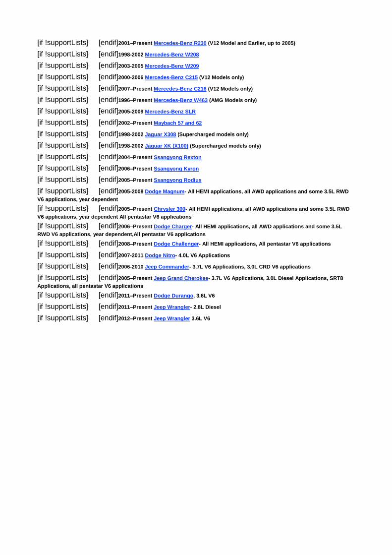
[if !supportLists]· [endif]2001–Present Mercedes-Benz R230 (V12 Model and Earlier, up to 2005)
[if !supportLists]· [endif]1998-2002 Mercedes-Benz W208
[if !supportLists]· [endif]2003-2005 Mercedes-Benz W209
[if !supportLists]· [endif]2000-2006 Mercedes-Benz C215 (V12 Models only)
[if !supportLists]· [endif]2007–Present Mercedes-Benz C216 (V12 Models only)
[if !supportLists]· [endif]1996–Present Mercedes-Benz W463 (AMG Models only)
[if !supportLists]· [endif]2005-2009 Mercedes-Benz SLR
[if !supportLists]· [endif]2002–Present Maybach 57 and 62
[if !supportLists]· [endif]1998-2002 Jaguar X308 (Supercharged models only)
[if !supportLists]· [endif]1998-2002 Jaguar XK (X100) (Supercharged models only)
[if !supportLists]· [endif]2004–Present Ssangyong Rexton
[if !supportLists]· [endif]2006–Present Ssangyong Kyron
[if !supportLists]· [endif]2005–Present Ssangyong Rodius
[if !supportLists]· [endif]2005-2008 Dodge Magnum- All HEMI applications, all AWD applications and some 3.5L RWD
V6 applications, year dependent
[if !supportLists]· [endif]2005–Present Chrysler 300- All HEMI applications, all AWD applications and some 3.5L RWD
V6 applications, year dependent All pentastar V6 applications
[if !supportLists]· [endif]2006–Present Dodge Charger- All HEMI applications, all AWD applications and some 3.5L
RWD V6 applications, year dependent,All pentastar V6 applications
[if !supportLists]· [endif]2008–Present Dodge Challenger- All HEMI applications, All pentastar V6 applications
[if !supportLists]· [endif]2007-2011 Dodge Nitro- 4.0L V6 Applications
[if !supportLists]· [endif]2006-2010 Jeep Commander- 3.7L V6 Applications, 3.0L CRD V6 applications
[if !supportLists]· [endif]2005–Present Jeep Grand Cherokee- 3.7L V6 Applications, 3.0L Diesel Applications, SRT8
Applications, all pentastar V6 applications
[if !supportLists]· [endif]2011–Present Dodge Durango, 3.6L V6
[if !supportLists]· [endif]2011–Present Jeep Wrangler- 2.8L Diesel
[if !supportLists]· [endif]2012–Present Jeep Wrangler 3.6L V6