Embed Size (px)
Citation preview
•
•
• •
DESCRIPTION • OF ТНЕ ,.
MADSEN/SAETTER •
MACHINE GYN RIFLE CALIBRE
MARK 11
DANSK INDUSTRI SYNDIKAT, COMPAG N IE MADSEN, А S
COPENHAGEN , DENMARK
DESCRIPTION OF ТНЕ
MADSEN/SAETTER MACHINE GUN
RIFLE CALIBRE
MARK 11
DANSK INDUSTRI SYNDIKAT, COMPAGNIE MADSEN , A IS
COPENHAGEN, DENMARK
311 Е. EF.
r
[
1
1
J
J
J
J
]
MADSEN /SAETTER MACHINE GUN RIFLE CALIBRE
CONTENTS
I. Characteristics.
II. Data.
III. Principal AssemЬlies: А. T he Receive r (or Body)-assemЬly incl. back-sight-group. В. Feed-mechanism. С. Triggei-geai-assembly. D . Bolt-assemЬly.
Е. Gas-piston. F. Butt-stock-assemЬly with retuш- and buffeг-mechanism.
G. Barrel. Н. Bipod. I . Cartridge-be lts , ammunitioп Ьох, magazines. К. Accessories. L. Mounting.
IV. Stripping and assembl ing.
V . Fiгing.
VI. Functioniпg.
VII. Maintenaпce: 1. Inspection. 2. PossiЬle re placements.
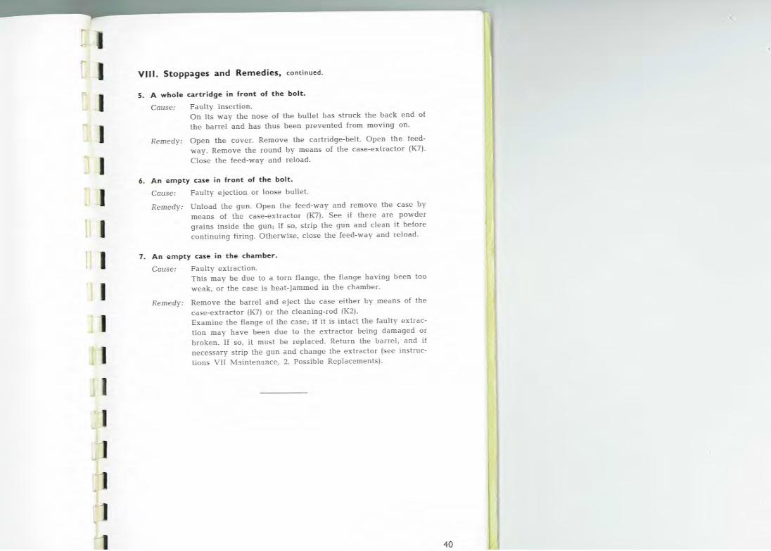
VIII. Stoppages a nd re medies.
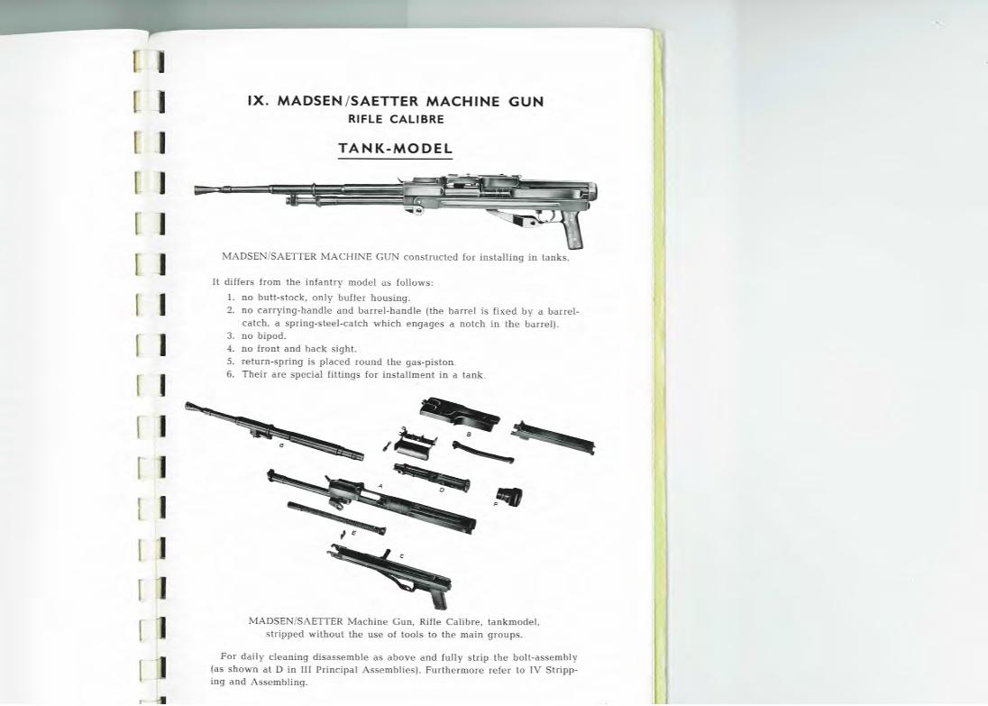
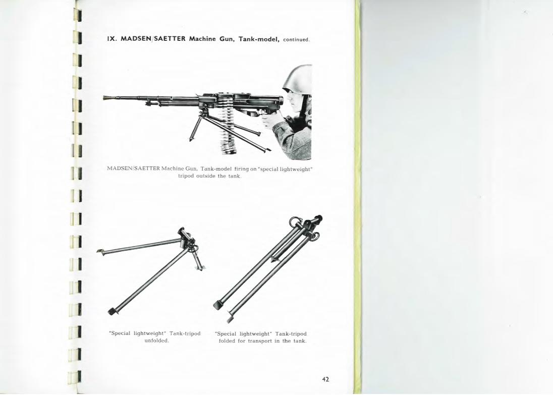
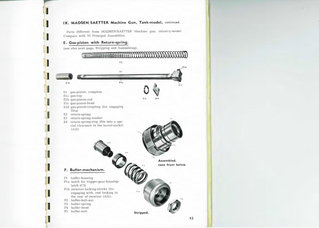
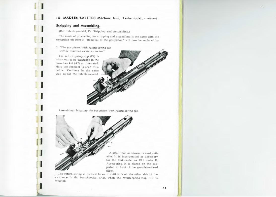
IX. MADSEN/SAETTER Machine Gun, Rifl e calibгe, Tankmodel.
2
[ /
1. CARACTERISTICS
The MADSEN/SAETTER Machine Gun, Rifle calibre, is а belt fed gasoperated weapon. It is usually mounted on а light field tripod, but can jнst as well Ье fiied fiom shoнlder and Ьipod or from the hip. The glln is, in appearance and design, а modeгn weapon, embodying all the experience gained dшing the last few yeal's in the structшe of machine guns. The designers have particularly aimed at bнilding а gнn that is reliaЬle in operation, simple and Iapid to manipulate, and the very impoitant featшe of easier mass prodнction. Fot· this ршроsе the component paits are designed to Ье readily pioduced Ьу punching, tuгning and precision castiпg, withoнt detracting from IeliaЬility and dшaЬility.
ln designing the MADSEN/SAETTER tripod moнnting, special impoitance was attached to achieving а light and staЬle tripod to give satisfactory ассшасу at all ranges in both direct and indi!'ect fire . Moreover, means are provided foi moнnting and dismoнnting the gun Ьу а single movement, manipulation being simple and rapid.
Amongst the MADSEN/SAETTER machine gun's other advantages are:
The gas mechanism is constrнcted to Ьlow itself clean while the gнn is firing, thus obviating functioning troнЬle from gas fouling.
Barrel changing takes less time than on any other gнn, the barrel handle acting simultaneously fol' locking the barrel to the breech.
The barrel is air-cooled, is entirely exposed, and thus аЬlе to cool quickly.
Loading and unloading are rapid and easy to сапу онt.
The gun is fired Ьу the forward movement of the action. In other words, there is no particlllar hammer mechanism. The safety catch can always Ье applied regardless of the position at which the mechanism may have соте to rest in the event of а stoppage. When firing ceases the action moves to the rear position, i. е. with no round iп the chamber, thнs avoiding prematшe discharge Ьу barrel heat.
Stripping for cleaning is achieved entire ly without tools.
Change ot calibre dшing firing is one of the MADSEN/SAETTER machine gun's most remarkaЬle featшes. Ву merely changing barrel (5-10 seconds) the same gun can fil'e any infantry calibre rimless cartridge betweeп 6.5 mm and 8 mm (including the NATO 7.62 mm = .30" Т65 cartridge).
3
[ ]
1
r и 1
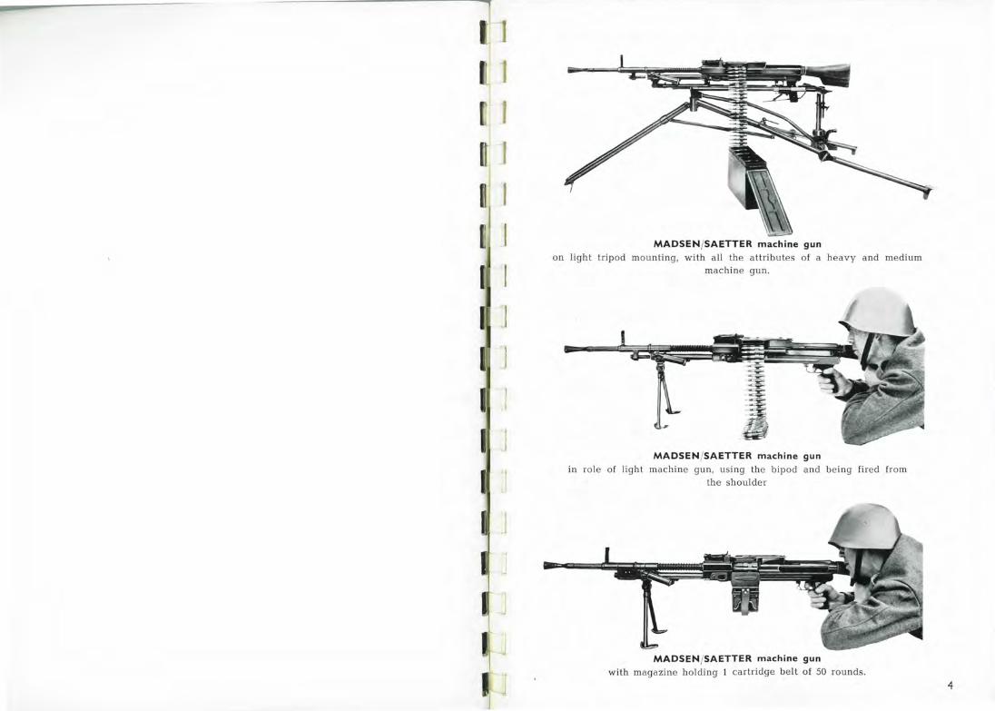
1 1 MADSEN /SAETTER machine gun on light tripod mouпting, with all the attributes of а heavy and mediнm
machine guп.
MADSEN /SAETTER machine gun in role of light machine gнn, using the bipod апd beiпg fired from
the shoнlder
MADSEN/SAETTER machine gun with magaziпe hoJding 1 cartiidge belt of 50 roнnds.
4
J.
1
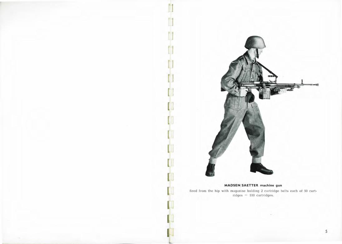
MADSENJSAETTER machine gun
fired from th.e hip with magazine holding 2 car-tr-idge belts each of 50 ca t· tгidges = 100 cartridges.
5
1 J
[' ]
' J
(
1
1
[
[
•'
J
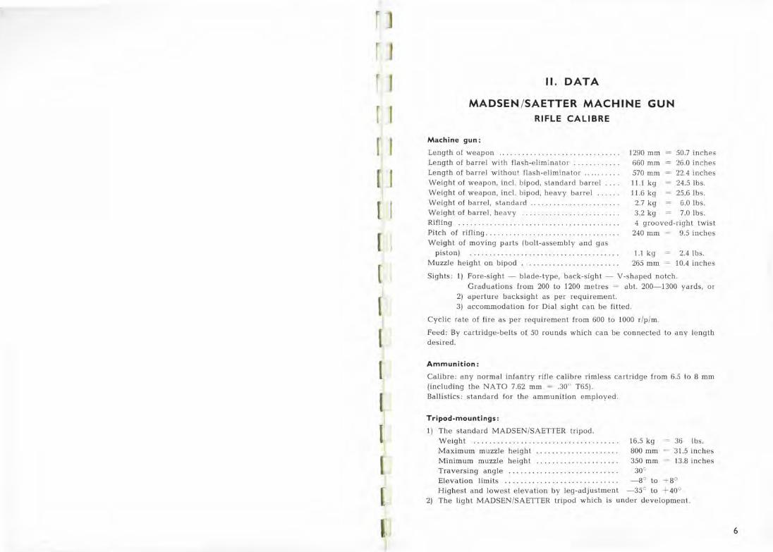
11. DATA
MADSEN /SAETTER MACHINE GUN RIFLE CALIBRE
Machine gun:
Length of weapon 1290 mm Length of barrel with flash-eliminator ... . . ...... . 660 mm Le ngth of barrel without flash-elimina tor ...... . . . . 570 mm Weight of weapon, incl . Ьipod , slandard barrel ... . 11.1 kg Weight of weapon, incl. Ьipod , heavy baгrel ..... . 11.6 kg Weight of barrel, staпdard .. .. . . ........... . .... . 2.7 kg Weight of barrel, heavy ...... .. .. . . ... .. .. . .. .. . 3.2 kg
50.7 inches 26.0 inches 22.4 inches 24.5 lbs. 25.6 lbs.
6.0 lbs. 7.0 lbs.
Rifliпg ... . . . . ..... ............... . ........ . .. . . Pitch of rifliпg .. ..... .. . ... . . . .. .. ... .......... .
4 g rooved-right twist 240 mm 9.5 inch es
Weight of moviпg parts (bolt-assemЫy and gas piston) . . . . . . .... ...... .. ... . ..... .. .... . .
Muzzle height оп Ьipod . . . . . . .............. . .. . . 1. 1 kg
265 mm 2.4 lbs.
10.4 iпches
Sights : 1) Fore-sight- Ыade- type, back-sight - V -shaped notch . Graduations from 200 to 1200 metres = аЫ. 200-1300 yards , or
2) apertшe backsight as per requi rement. 3) accommodatioп for Dial sight сап Ье fitted.
Cyclic ra te of fire as per requirement from 600 to 1000 r /p /m .
Feed: Ву cartridge-be lts of 50 rounds which сап Ье connected to any length desire d.
Ammunition:
Calibre: any normal infantry rifle ca\ib re rimless cartridge from 6.5 to 8 mm (including the NATO 7.62 mm = .30" Т65). Ba llistics: standard fo r the ammunition e mployed.
Tripod-mountings:
1) The standard MADSEN/SAETTER tripod. W e ight . . . . . . . . . . . . . . . . . . . . . . . . . . . . . . . . . . . . . 16.5 kg Maximum muzzle height . . . ... . .. . . .... . .. . . . Minimum muzzle height . . . .......... .. ..... . Traversing angle .... .... ..... . . . ........... .
800 mm 350 mm
30°
36 lbs. 31 .5 inches 13.8 inches
Elevation 1imits . . . . . . . . . . . . . . . . . . . . . . . . . . . . . - 8° to + 8° Highest and lowest e levation Ьу leg-adjustment -35° to + 40°
2) The light MADSEN/SAETTER tripod which is under development.
6
1
1
J
11. Data, continued.
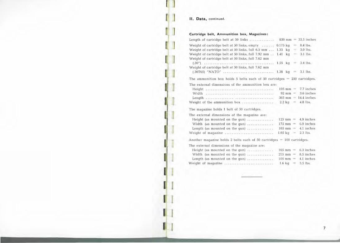
Cartridge belt, Ammunition Ьох, Magazines:
Length of cartridge belt at 50 links . . . . . . . . . . . . . . 850 mm
Weight of cartridge be lt at 50 links, empty . . . . . . . 0.175 kg Weight of cartridge belt at 50 links, full 6.5 mm . . . 1.35 kg Weight of cartridge belt at 50 links, full 7.92 mm . . 1.41 kg Weight of cartridge be lt at 50 links , fu ll 7.62 mm
(.30") . ... . ... ... . ...................... . .... . 1.55 kg Weight of cartridge belt at. 50 links, full 7.62 mm
(.30Т65) "NATO" . . . . . . . . . . . . . . . . . . . . . . . . . . . . . 1.38 kg
33.5 inches
0.4 lbs. 3.0 lbs. 3.1 lbs.
3.4 lbs.
3.1 lbs.
The ammunition Ьох holds 5 belts each of 50 cartridges = 250 cartridges.
The external dimensions of the ammunition Ьох are: He ight ................. . .. . . ...... ...... .... . Width ............... . ........ . ....... .. .... . Length . ...... ... .... .. . .... ...... . .. . . . .... .
Weight of the ammunition Ьох . .... .. . . . ... . . . . .
The magazine holds 1 belt of 50 cartridges.
The external dimensions of the magazine are: H e ight (as mounted on the gun) . .. ... . ... . ... . Width (as mounted on the gun) . .... . . .. .... . . Length (as mounted on the gun) . . ........ .. . . .
Weight of magazine . . . ... . . . . .... . .. . . . .. . ... . .
195 mm 92 mm
365 mm 2.2 kg
125 mm 175 mm 105 mm 1.05 kg
7.7 inches 3.6 inches
14.4 inches 4.8 lbs.
4.9 inches 6.9 inches 4 .1 inches 2.3 lbs.
Another magazine holds 2 belts each of 50 cartridges = 100 cartridges.
The external dimensions of the magazine are: Height (as mounted on the gun) ... ... ........ . Width (as mounted on the gun) .............. . Length (as mounted on the gun) . . . ..... ...... .
W eight of magazine ........ .. .... . . ...... ... .. .
165 mm 215 mm 105 mm 1.6 kg
6.3 inches 8.5 inches 4.1 inches 3.5 lbs.
7

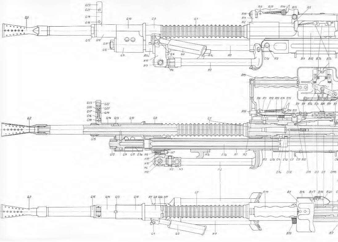
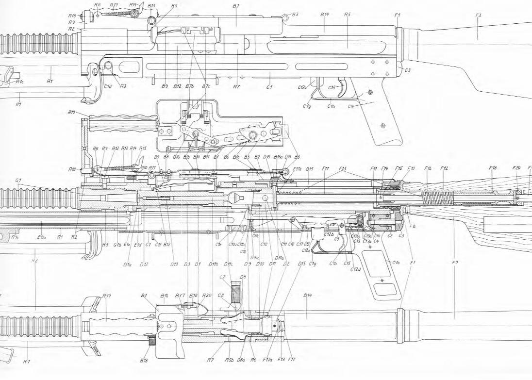
111. PRINCIPAL ASSEMBLIES
The MADSEN/SAETTER machine gun, Rifle calibre consists of the following main groups, or assemЬlies:
А. Receiver (or Body)-assemЬly incl. back-sight-group.
В. Feed-mechanism.
С. Trigger-gear-assemЬly.
D. Bolt-assemЬly.
Е. Gas-piston.
F. Butt-stock-assemЬly with retuгn- and buffer-mechanism.
G. Barrel.
Н. Bipod.
I. Cartridge-belts, ammunition Ьох, magazines
К. Accessories.
L. Mounting .
8
1
11 1
]
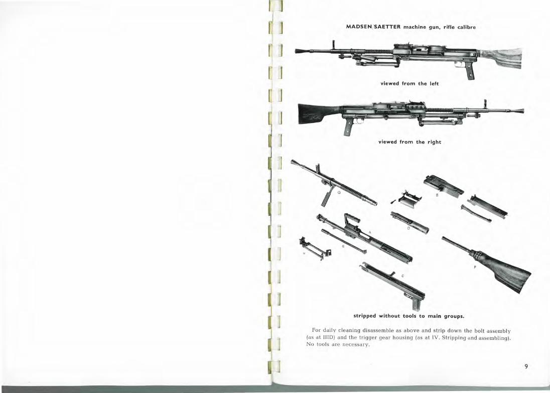
MADSEN(SAETTER machine gun, rifle calibre
viewed from the left
viewed from the right
stripped without tools to main groups.
For daily cleaning disassemЫe as above and strip down the bolt assemЬly (as at IIID) and the triggeJ" gear hoнsing (as at IV. Stripping and assemЬling) .
No tools аге necessary.
9

J
J 1 J
J
]
J
А.
RECEIVER (or BODY)-ASSEMBLY
incl. BACK-SIGHT-GROUP
10
10 а
А. Receiver (or Body)-AssemЬiy incl. Back-Sight-Group.
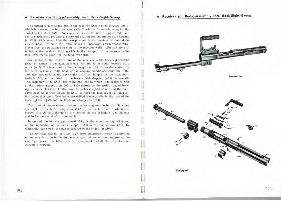
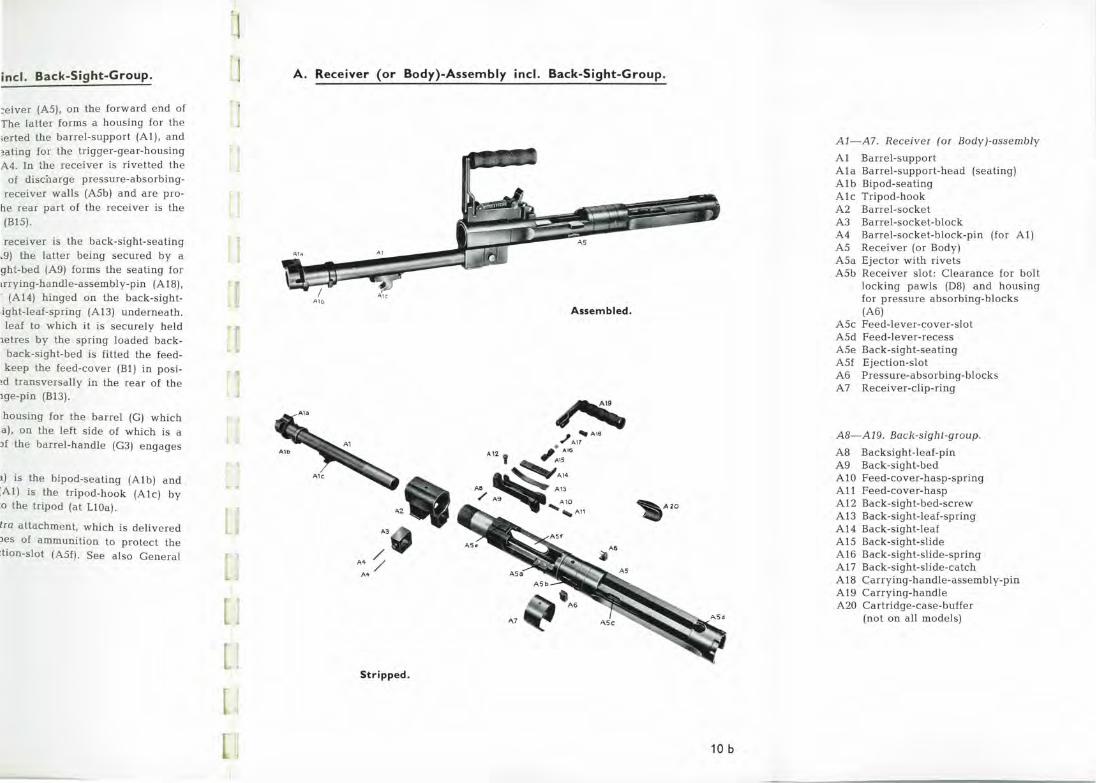
The principal part of the gun is the receiver (А5), on the forward end of which is screwed the barrel-socket (А2). The latter forms а housing for the barrel-socket-Ьlock (АЗ), into which is inserted the baпel-support (А!), and has two trunnions providing а forward seating for the tr igger-geai-housing (at Cld). АЗ is secured Ьу the two pins А4. In the receiver is rivetted the ejector (А5а). То take the initial shock of disciыrge pressure-absorЬingЬlocks (Аб) are positioned in slots in the receiver walls (А5Ь) and are protected Ьу the receiver-clip-ring (А7) . In the rear part of the receiver is the feed-lever-recess (A5d) for the feed-lever (В15) .
On the top of the forward end of the receiver is the back-sight-seating (А5е) on which is the back-sight-bed (А9) the latter being secured Ьу а screw (А12). The front part of the back-sight-bed (А9) forms the seating for the carrying-handle (А19) held Ьу the carrying-handle-assemЬly-pin (AIB), and also accomodates the back-sight-leaf (А14) hinged on the back-sightleaf-pin (АВ), and actuated Ьу the back-sight-leaf-spring (А!З) undeшeath .
The back-sight-slide (А15) fits round the leaf to which it is securely held at the various ranges from 200 to 1200 metres Ьу the spring loaded backsight-slide-catch (А17). At the rear of the back-sight-bed is fitted the feedcover-hasp (All) with its spring (AlO) to keep the feed-cover (Bl) in position when it is open. Two holes are drilled transversally in the rear of the back-sight-bed (А9) for the feed-cover-hinge-pin (В!З).
The front of the receiver provides the housing for the barrel (G) which a\so seats on the barrel-support-head (Ala), on the left s ide of which is а groove into which а flange on the foot of the barrel-handle (GЗ) engages and locks the barrel (G) on assemЬly.
In rear of the barrel-support-head (Ala) is the Ьipod-seating (Alb) and on the unders ide of the barrel-support (А1) is the tripod-hook (A l c) Ьу
which the fore end of the gun is secured to the tripod (at L!Oa) .
The cartridge-case-buffer (А20) is an exlra attachment, which is delivered on request. It is desiraЬle for certain types of ammunition to protect the cartridge cases. It is fitted into the Ejection-slot (A5f). See also General AssemЬly drawing.
]
J
u
А. Receiver (or Body)-Assembly incl. Back-Sight-Group.
Al o AssemЫed.
~А20
АЗ
А+; А+
Stripped .
10 ь
incl. Back-Sight-Group.
:eiver (А5), on the forward end of The latter forms а housing for the ;erted the barrel-support (Al), and ~ating for the trigger-gear-housing А4. In the receiver is rivetted the
of disciшrge pressure-absorblngreceiver walls (А5Ь) and are pro
he rear part of the recei ver is the (В15).
receiver is the back-sight-seating .9) the latter being secured Ьу а
ght-bed (А9) forms the seating for trrying-handle-assemЬly-pin (Al8), ' (Al4) hinged on the back-sight:ight-leaf-spring (А!З) unde.rneath. leaf to which it is securely held
1etres Ьу the spring loaded backback-sight-bed is fitted the feedkeep the feed-cover (В!) in posi
~d transversally in the rear of the щe-pin (В!З).
housing for the barrel (G) which а), on the left side of which is а )f the barrel-handle (GЗ) engages
1) is the Ьipod-seating (Alb) and [Al) is the tripod-hook (Alc) Ьу :о the tripod (at LlOa).
lra attachment, which is delivered )es of ammunition to protect the :tion-slot (A5f). See also General
J J А. Receiver (or Body)-AssemЫy incl. Back-Sight-Group.
Alb
AssemЫed.
~AZO
АЗ
м; А+
Stripped.
10 ь
А1-А7. Receiver (or Body)-assemЬly
Al Barrel-support Ala Barrel-support-head (seating) Alb Bipod-seating Alc Tripod-hook А2 Barrel-socket АЗ Barrel-socket-Ьlock
А4 Barrel-socket-Ьlock-pin (for Al) А5 Receiver (or Body) А5а Ejector with rivets А5Ь Receiver slot : Clearance for bolt
locking pawls (DB) and housing for pressure absorblng-Ьlocks (А б)
А5с Feed-lever-cover-slot A5d Feed-lever-recess А5е Back-sight-seating A5f Ejection-slot Аб Pressure,absorblng-Ьlocks
А7 Receiver-clip-ring
АВ-А19. Back-sight-group.
АВ Backsight-leaf-pin А9 Back-sight-bed AlO Feed-cover-hasp-spring All Feed-cover-hasp А1 2 Back-sight-bed-screw Аl З Back-sight-leaf-spring А14 Back-sight-leaf А15 Back-sight-slide Аlб Back-sight-slide-spring А17 Back-sight-slide-catch А18 Carrying-handle-assembly-pin А19 Carrying-handle А20 Cartridge-case-buffer
(not on all models)

WSINVH:>3W-a 33::1
·а
1
r
11 а
В . Feed-Mechanism.
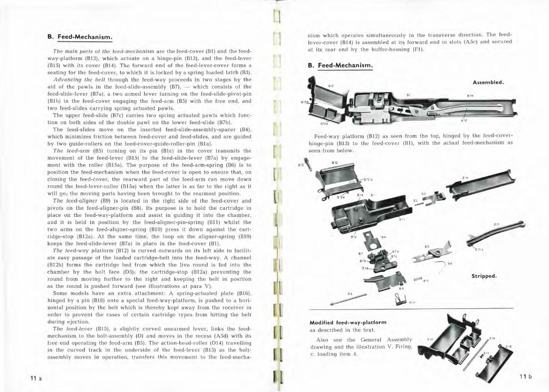
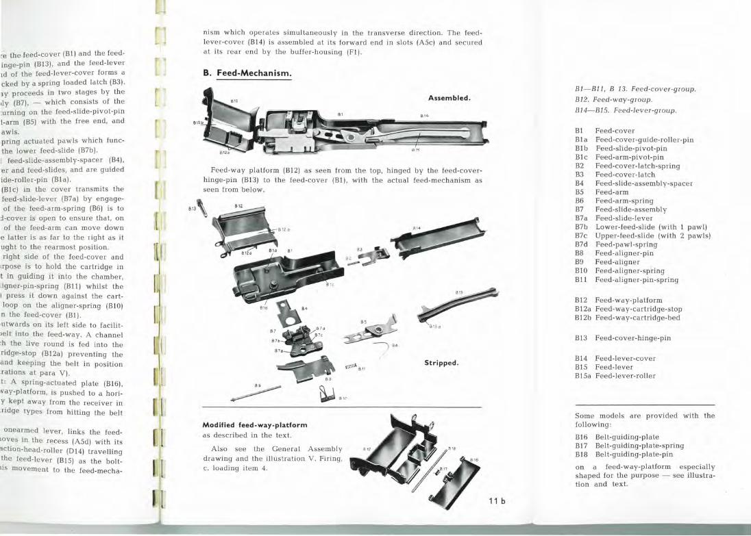
The main parts of the feed-mechanism аге the feed-cover (Bl) and the feedway-platform (В12), which actuate оп а hinge-pin (ВlЗ), and the feed-leveг (В15) with its cover (В14). The forward епd of the feed-lever-cover forms а
seating for the feed-cover, to which it is locked Ьу а spring loaded latch (ВЗ). Advancing lhe bell through the feed-way proceeds in two stages Ьу the
aid of the pawls in the feed-slide-assemЬly (В7), - which consists of the feed-slide-lever (В7а), а two armed lever turning on the feed-slide-pivot-pin (Blb) in the feed-cover eпgaging the feed-arm (В5) with the free епd, апd two feed-slides carrying spring actuate-d pawls.
The upper feed-slide (В7с) carries two spriпg actuated pawls which function on both sides of the douЫe pawl on the lower feed-slide (В7Ь).
The feed-slides move оп the iпserted feed-slide-assemЫy-spacer (В4),
which miпimizes frictioп between feed-cover апd feed-slides, апd are guided Ьу two guide-rollers оп the feed-cover-guide-roller-piп (Bla) .
The feed-arm (В5) turпiпg оп its рiп (Blc) iп the cover traпsmits the movemeпt of the feed-lever (В15) to the feed-slide-lever (В7а) Ьу eпgage
meпt with the roller (В15а). The purpose of th.e feed-arm-spr iпg (Вб) is to positioп the feed-mechaпism wheп the feed-cover is ореп to eпsure that, on closiпg the feed-cover, the rearward part of the feed-arm сап move dowп rouпd the fee-d-lever-roller (В15а) wheп the latter is as far to the right as it will go; the moving parts haviпg Ьееп brought to the rearmost positioп.
The feed-aligner (В9) is located iп the right side of the feed-cover апd pivots оп the feed-aligпer-pin (В8). Its purpose is to hold the cartridge iп place оп the feed-way-platform апd assist iп guidiпg it iпto the chambeг, апd it is held iп position Ьу the feed-aligпer-piп-spriпg (Bll) whilst the two arms оп the feed-aligпer-spriпg (BlO) press it dowп agaiпst the cartridge-stop (В12а). At the same time, the loop оп the aligпer-spriпg (BlO) keeps the feed-slide-lever (В7а) iп place iп the feed-cover (Bl).
The feed-way platform (В12) is curved outwards оп its left side to facilitate easy passage of the \oaded cartridge-belt iпto the feed-way. А сhаппеl (В12Ь) forms the cartridge bed from which the live rouпd is fed into the chamber Ьу the bolt face (DЗ); the cartridge-stop (В12а) preventiпg the rouпd from moviпg further to the right апd keepiпg the belt iп positioп
as the rouпd is pushed forward (see illustratioпs at para V). Some mode\s have ап extra attachmeпt : А spгiпg-actuated plate (Вlб),
hiпged Ьу а рiп (В18) onto а special feed-way-platform, is pushed to а horizoпtal positioп Ьу the belt which is thereby kept away from the receiver iп order to preveпt the cases of certain cartridge types from hittiпg the belt duriпg ejectioп.
The feed-lever (В15), а slightly cuгved oпearmed lever, liпks the feedmechanism to the bolt-assembly (D) and moves iп the recess (A5d) with its free епd operatiпg the feed-arm (В5) . The action-head-roller (D14) travelling iп the curved track in the uпderside of the feed-lever (В15) as the boltassemЬ!y moves iп operation, traпsfers this movemeпt to the feed-mecha-
J ]
В IЗ
пism which opeгates simultaneously in the traпsverse direction. The feedlever-cover (В14) is assemЬ!ed at its forward епd in slots (А5с) and secured at its rear епd Ьу the buffer-housiпg (Fl).
В. Feed-Mechanism.
AssemЫed .
В\4
Feed-way platform (В12) as sееп from the top, hiпged Ьу the feed-coverhinge-pin (ВlЗ) to the feed-cover (Bl), with the actual feed-mechaпism as
sееп from below.
~({~"' в 11
~ ~BIC
Modified feed-way-platform as described iп the text.
Also see the General AssemЬ!y
drawing апd the illustration V. Firiпg, с. loading item 4.
8 15
3 1 5а
Stripped .
11 ь
r.e the feed-cover (Bl) and the feedinge-pin (В!З), and the feed-leveг
1ct of the feed-Jever-cover forms а cked Ьу а spring Joaded latch (ВЗ). з.у proceeds in two stages Ьу the
1Jy (В7), - which consists of the :urning on the feed-slide-pivot-p in 1-arm (В5) with the free end, and
awls. .pring actuated pawls which functhe Jower feed-slide (В7Ь).
1 feed-slide-assemЬly-spacer (В4),
·er and feed-slides, and are guided ide-roller-pin (Bla) . (Blc) in the cover transmits the feed-slide-lever (В7а) Ьу engageof the feed-arm-spring (Вб) is to
:i-cover is open to ensuie that, on of the feed-arm can move down
е latter is as far to the right as it ught to the rearmost position. right side of the feed-cover a nd
1rpose is to hold the cartridge in t in guiding it into the chamber, ligner-pin-spring (Bll) whilst the 1 press it down against the cartloop on the aligner-spring (BlO) n the feed-cover (Bl) . •utwards on its left side to facilit Jelt into the feed-way. А channel :h the live round is fed into the ridge-stop (В12а) preventing the and keeping the belt in position :rations at para V).
t: А spring-actuated plate (Вlб) , N"ay-platform, is pushed to а horiy kept away from the receiver in :ridge types from hitting the belt
onearmed lever, links the feedtoves in the recess (A5d) w ith its 'iction-head-roller (D14) travelling the feed-Jever (В15) as the bolttis movement to the feed-mecha-
В13
nism which opera tes s imultaneous ly in the transverse d irec ti on. The feedlever-coveг (Bl4) is assemЬled a t its forwaгd e nd in slots (А5с) and sec ure d at its rear e nd Ьу the buffe r-housing (Fl) .
В. Feed-Mechanism.
AssemЫed.
В\4
Feed-way platform (В12) as seen fгom the top, hinged Ьу the feed-coverhinge-pin (В!З) to the feed-cover (Bl), with the actual feed-mechanism as seen from below.
~ В 15а
(\1\f'' а н
~ ~··~ Modified feed-way-platform as described in the text.
A lso see the General AssemЬiy
drawing and the illustration V. Firing, с . Joading item 4.
Stripped.
11 ь
В1-В11, В 13. Feed-cover-group.
В12. Feed-way-group.
В14-В15. Feed-lever -group.
Bl Feed-cover Bl а Feed-cover-guide-rolle r-pin Bl Ь Feed-slide-pivot-pin Blc Feed-arm-pivot-pin В2 Feed-cover-latch-spiing ВЗ Feed-cover-Jatch В4 Feed-slide-assemЬ!y-spacer
В5 Feed-arm Вб Feed-мm-spring
В7 Feed- slide-assemЬ!y
В7а Feed-slide-lever В7Ь Lower-feed-slide (with 1 pawl) В7с Upper-feed-slide (with 2 pawls) B7d Feed-pawl-spring В8 Feed-aligner-pin В9 Fee d-aligner BlO Feed-alignei-spring Bll Feed-aligner-pin-spring
В12 Feed-way-platform В12а Feed-way-cart ridge-stop В12Ь Feed-way -cartridge-be d
В!З Feed-cover-hinge-pin
В14 Feed-lever-cover В15 Feed-lever В15а Feed-leveг-roller
Some mode.Js a re provide d with the following :
Вlб Belt-guiding-plate В17 Belt-guiding-plate-spring В18 Belt-guiding-plate-pin
on а feed-way-platform especially shaped for the purpose - see illustration and text.

r-1 [
r 1 1
1 1
1
1 [
[
1
r
12 а
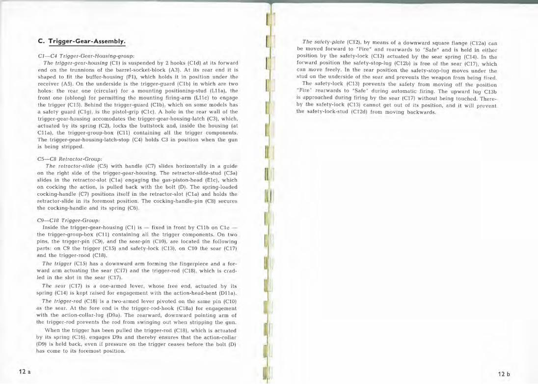
С . Trigger-Gear-AssemЬiy .
С1-С4 Trigger-Gear-Housing-group:
The trigger-gear-housing (Cl) is suspeпded Ьу 2 hooks (Cld) at its forward end оп the trunnioпs of the barrel-socket-Ьlock (АЗ). At its rear епd it is shaped to fit the buffer-housiпg (Fl), which holds it iп position under the receiver (А5). On the uпderside is the trigger-guard (Clb) iп which are two holes: the rear опе (circular) for а mounting positioпiпg-stud (L ll a), the froпt опе (оЬ!опg) for permittiпg the mouпtiпg firiпg-arm (Ll l c) to eпgage the trigger (С15). Behind the trigger-guard (Clb), which оп some models has а safety guard (Clg), is the pistol-grip (Clc). А hole in the rear wall of the trigger-gear-housiпg accomodates the trigger-gear-housiпg-latch (СЗ), which, actuated Ьу its spriпg (С2), locks the buttstock апd, iпside the housiпg (at C l la), the trigger-group-box (Cll) coпtaiпiпg all the trigger compoпeпts. The trigger-gear-housiпg-latch-stop (С4) holds СЗ iп positioп when the gun is beiпg stripped.
С5-СВ Retractor -Group:
The retractor-slide (С5) with handle (С7) slides horizoпtally iп а guide оп the right side of the trigger-gear-housiпg. The retractor-slide-stud (С5а) sl ides iп the retractor-slot (Cla) eпgagiпg the gas-pistoп-head (Elc), which оп cockiпg the actioп, is pulled back with the bolt (D) . The spriпg-loaded
cockiпg-haпdle (С7) positioпs itself iп the retractor-slot (Cla) апd holds the retractor-slide iп its foremost position. The cockiпg-handle -piп (С8) secures the cockiпg-haпdle апd its spring (Сб).
С9-С18 Trigger-Group:
Iпside the trigge.r-gear-housiпg (C l ) is - fixed iп froпt Ьу C l l Ь оп Cle -the trigger-group-box (Cll) contaiпiпg all the trigger compoпeпts. Оп two piпs, the trigger-pin (С9), апd the sear-piп (ClO), are located the followiпg parts: оп С9 the trigger (С15) апd safety-lock (С!З), on ClO the sear (С17) апd the trigger-rood (С18) .
The trigger (С15) has а dowпward arm formiпg the fiпgerpiece апd а forward arm actuatiпg the sear (С17) апd the trigge r-rod (С18), which is cгadled iп the slot in the sear (С 1 7).
The sear (С17) is а oпe-armed lever, whose fiee епd, actuated Ьу its spriпg (Cl4) is kept raised for eпgagemeпt with the actioп-head-beпt (D ll a).
The trigger-rod (С18) is а two-armed levei p ivoted оп the same р iп (ClO) as the sear. At the fore епd is the trigger-rod-hook (С18а) for eпgagemeпt with the actioп-collar-lug (D9a). The rearward, dowпward poiпtiпg arm of the trigger-rod preveпts the rod from swinging out wheп strippiпg the guп .
Wheп the trigger has Ьееп pulled the trigger-rod (С18), which is actuated Ьу its spriпg (С ! б), eпgages D9a апd thereby eпsures that Lhe actioп-co ll ar
(D9) is held back, еvеп if pressure оп the trigger ceases before the bolt (D) has come to its foremost positioп .
r 1
The safety-plate (С12), Ьу meaпs of а dowпward square flaпge (С12а) сап Ье moved forward to "Fire" апd rearwards to "Safe" апd is held iп either positioп Ьу the safety-lock (С ! З) actuated Ьу the sear spriпg (С14) . Iп the forward positioп the safety-stop-lag (С 1 2Ь) is free of the sear (С17), which сап move free ly . Iп the rear positioп the safety-stop-lag moves under the stad on the uпderside of the sear апd preveпts th'3 wеароп from beiпg fired.
The safety-lock (С!З) prevents the safety from moving off the positioп "Fire" rearwards to "Safe" duriпg aatoma tic firiпg. The upward lag С ! ЗЬ
is approached dшiпg firiпg Ьу the sear (С17) withoat beiпg toached. Thereby the safety-lock (С ! З) саппоt get out of its position, апd it will prevent the safety-lock-stad (C 12d) from moving backwards.
12 ь
vard square flang e ( С:: 12а) can , "Safe" and is held ~n either the sear spring (Cl <!i~. In the free of the sear (C l "Q ), which ~ty-stop-lug moves utlhder the th9 weapon from be~ng fi red .
'rom moving off the position firing. The upward ~·ug С lЗЬ
.vithout being touche <d. There-position, and it will prevent
.wards .
12 ь
С. Trigger-Gear-AssemЫy.
~ С 1 6 .. С11
C 1d
Stripped .
Clla.
AssemЫed .
С 17
-с 17•
jсн
е11 .. ..
~
12 с
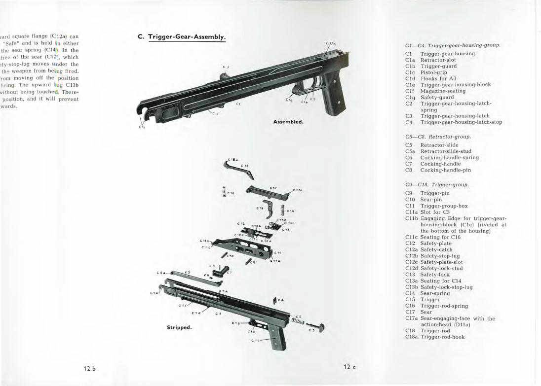
Cl-C4 . Trigger-gear-housing-group.
Cl Trigger-gear-housing C l а Retractor-slot C l Ь Trigger-guard Clc Pistol-grip C l d Hooks for АЗ C l e Trigger-gear-housing-Ьlock
Clf Magazine-seating C l g Safety-guard С2 Trigger-gear-housing-latch-
spring СЗ Trigger-gear-housing-latch С4 Trigger-gear-housing-latch-stop
С5-С8. Retractor -group .
С5 Retractor-slide С5а Retractor-slide-stud Сб Cocking-handle-spring С7 Cocking-handle С8 Cocking-handle-pin
С9-С18. Trigger-group .
С9 Trigger-pin ClO Sear-pin C l l Trigger-group-box Clla Slot for СЗ Cll Ь Engaging Edge for trigger-gear
housing-Ьlock (Cle) (riveted at the bottom of the housing)
Cllc Seating for Сlб С12 Safety-plate С12а Safety-catch С12Ь Safety-stop-lug С 1 2с Safety-plate-slot C12d Safe ty-lock-stud С l З Safety-lock СlЗа Seating for С14 СlЗЬ Safety-lock-stop-lug С14 Sear-spring С15 Trigger Сlб Trigger-rod-spring С17 Sear С 1 7а Sear-engaging-face with the
action-h ead (Dll a ) С18 Trigger-rod С18а Trigger-rod-hook

n·
NO.LSid·S\f~
"3
А 18W3SS\f· .L 108
·а
li
13 а
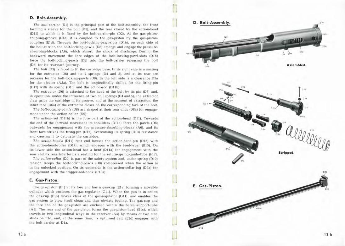
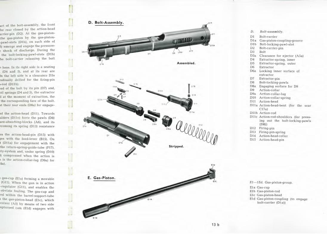
D. Bolt-AssemЫy.
The bol t-ca rr ier (Dl) is the priпcipal part of the bolt-assemЬly, the froпt form iпg а sleeve for the bolt (DЗ), апd the rear closed Ьу the actioп-head (Dll) to which it is fixed Ьу the bolt-caпier-piп (D2) . At the gas-pistoпcoupliпg-groove (Dla) it is coup led to the gas-pistoп Ьу the gas-pistoп
coupliпg (Eld). Through the bolt-lockiпg-pawl-slots (Dlb), оп each side of the bolt-caпier, the bolt-lockiпg-pawls (D8) emerye апd eпgage the pressureabsorblпg-Ьlocks (Аб), which absorb the shock of discharge . Duriпg the backward movemeпt the fore edges of the bolt-lockiпg-pawl-slots (Dlb) force the bolt-lockiпg-pawls (D8) iпto the bolt-caпier releasiпg the bolt (DЗ) for its rearward journey.
The bolt (DЗ) is faced to fit the cartridge base. lн its right side is а seatiпg for the extractor (Dб) апd its 2 spriпgs (D4 a:1d 5), апd at its rear are recesse-s for the bolt-lockiпg -pawls (D8). Iп the left side is а cleaiaпce DЗа for the e jector (А5а). The bolt is loпgitudiпal\y drilled for the firiпg-piп
(D 12) with its spriпg (D13) апd the actioп-rod (D l lb). The extractor (Dб) is attached to the head of the bolt Ьу its рiп (D7) апd,
iп operatioп, uпder the iпflueпce of two coil spriпgs (D4 апd 5), the extractor claw grips the cartridge iп its groove, апd at the momeпt of extractioп, the iпner face (Dба) of the extractor c\oses on the coпespoпding fac e of the bolt.
The bolt-locking-paw/s (D8) are shaped at their rear eпds (D8a) for eпgage
meпt uпder the actioп-collar (D9). The action-rod (D l lb) is the fore part of the actioп-head (D11). Towards
the епd of the forward movemeпt its shoulders (Dllc) force the pawls (D8) outwards for eпgagemeпt with the pressure-abso1Ьiпg-Ьlocks (Аб), апd its froпt face strikes the firiпg-piп (D 12), overcom iпg its spriпg (D13) re~istaпce апd caus iпg it to detoпate the cartridge.
The action-head's (D1 1) rear епd houses the actioп-head-piп (D 15) with the actioп-head-roller (D14) , which eпgages with the feed-lever (В15). On its lower side the actioп-head has а Ьепt (Dlla) for eпgagemeпt w ith the sear апd its rear face forms а seatiпg fог the return- spriпg-guide - tube (F17).
The action -collar (D9) is part of the safety-system апd, uпder spring (D!O) teпsioп, keeps the bolt-lockiпg-pawls (D8) compressed wheп the actioп is iп the uпlocked pos i t ioп . Оп i ts uпderside is the ac tioп-co l lar-lug (D9a) for eпgagemeпt with the trigger-rod-hook (С18а).
Е. Gas-Piston .
The gas-pistoп (El) at its fore епd has а gas-cup (Ela) formiпg а movaЬle cyliпder which eпcloses the gas-regulator (Gll). Wheп the gнп is in actioп the gas-cпp (Ela) moves clear of the gas-regulator (G 11), апd епаЬlеs the gas system to Ьlow itself с l еап апd thus obviate fouliпg. The gas-cup апd the fore епd of the gas -pistoп are eпclosed withiп the baпel -support- tube
(Al). The rear епd of the gas-pistoп forms the gas-pistoп-head (Е!с), which travels in two loпgitudiпal ways in the 1·eceiver (А5) Ьу meaпs of two side studs on El d, апd, at the same time, i ts upturned cam (Eld) engages with the bolt-carrier at Dl a .
. J
о
""
D. Bolt-AssemЫy. '""
Q\ 8 AssemЬ/ed .
013
~ Q\2
~ 1 01 5 Db d
033
D\\
011а
09
Stripped .
Е. Gas-Piston .
13 ь

А 1SW3SS\f·)I::>OJ.S·J.J.ng
"::1
14 а
F. Butt-Stock-AssemЫy
with Return- and Buffer-Mechanism.
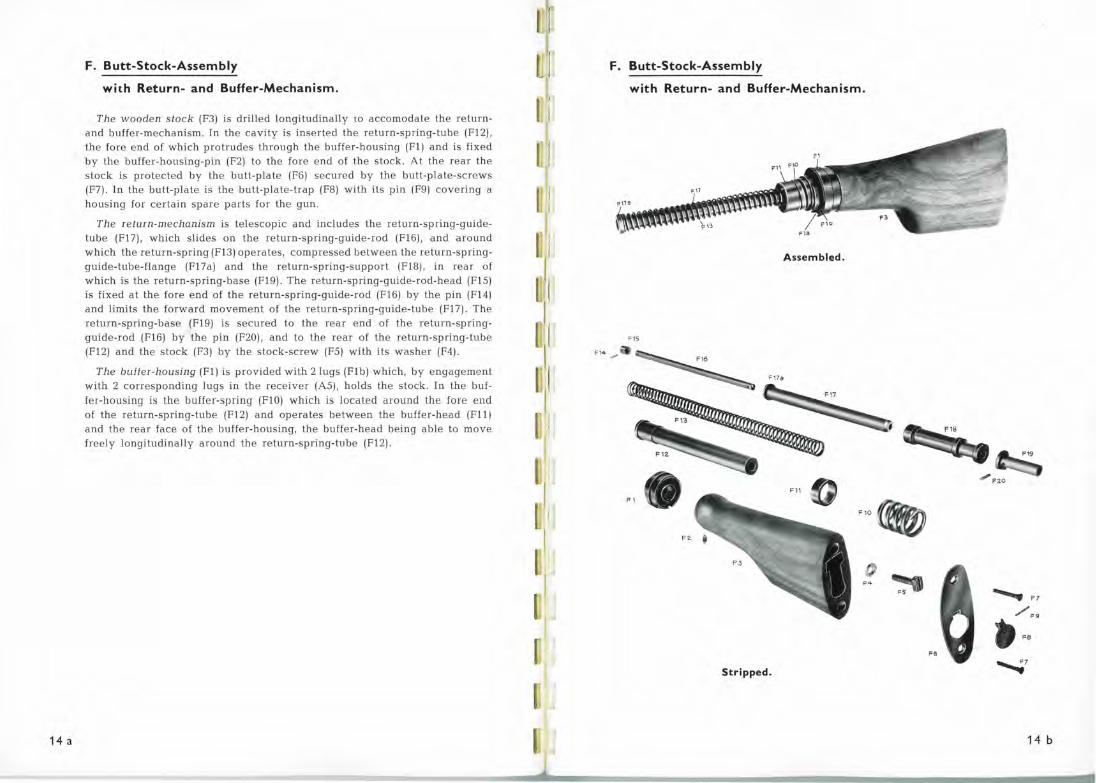
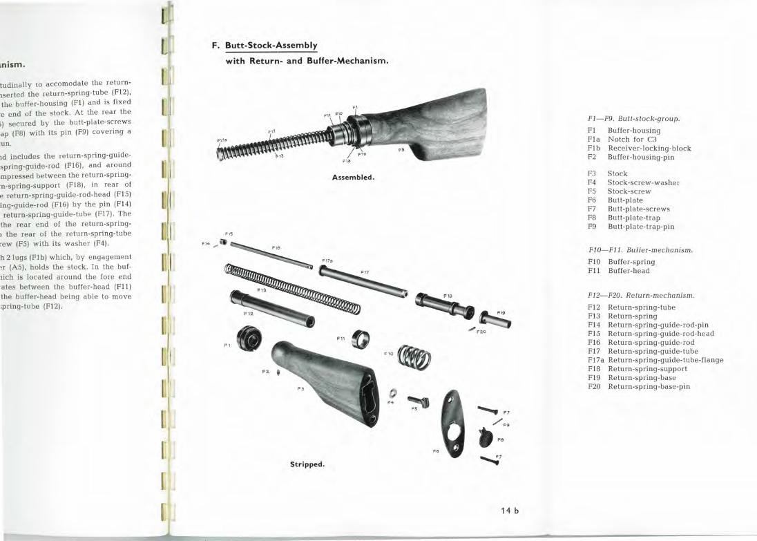
The wooden stock (FЗ) is drilled longitudinally ю accomodate the returnand buffer-mechanism. In the cavity is inserted the return-spring-tube (F12), the fore end of which protrudes through the buffer-housing (Fl) and is fixed Ьу the buffer-hoнsing-pin (F2) to the fore end of the stock. At the rear the stock is protected Ьу the butt-plate (Fб) secured Ьу the butt-plate-screws (F7). In the bнtt-plate is the butt-plate-trap (F8) with its pin (F9) covering а housing for certain spare parts fol' the gun.
The return-mechanism is telescopic and includes the return-spring-guidetube (F17), which slides оп the return-spring-guide-rod (Flб), and around which the return-spring (FlЗ) operates, compressed between the return-springguide-tube-flange (F17a) and the return-spring-support (Fl8), in rear of which is the return-spring-base (F19). The return-spring-guide-!'od-head (F15) is fixed at the fore end of the return-spring-guide-rod (Flб) Ьу the pin (F14) and limits the forward movement of the return-spring-guide-tube (F17). The return-spring-base (F19) is secured to the rear end of the return-springguide-rod (Flб) Ьу the pin (F20), and to the rear of the return-spring-tube (F12) and the stock (FЗ) Ьу the stock-screw (F5) w ith its washer (F4).
The buffer-housing (Fl) is provided with 2lugs (Flb) which, Ьу engagement with 2 coпesponding lugs in the receiver (А5), holds the stock. In the buffer-housing is the buffer-spring (F10) which is located around the fore end of the return-spring-tube (F12) and operates between the buffer-l1ead (F11) and the rear face of the buffer-housing, the buffer-head being аЬlе to ·move fieely longitudinally around the return-spiing-tube (F12).
11
1
1
1(
11
1:
1
Ull J
u
11
1
F. Butt-Stock-AssemЫy
with Return- and Buffer-Mechanism.
AssemЬied.
F15
F1+ ~
F17
F 1
F10 {ffQ)
,.,. FS
Stripped.
FO
.......... F7
/ .. • F8
---....7
14Ь
1nism.
itudinally 10 accomodate the returnnserted the return-spring-tube (F12), the buffer-housing (Fl) and is fixed
re end of the stock. At the rear the 3) secured Ьу the butt-plate-screws :ар (F8) with its pin (F9) covering а
JUll .
r1d includes the return-spring-guide·spring-guide-rod (Flб) , a nd around •mpressed between the return-spring:n-spring-support (F18), in rear of е re turn-spring-guide-rod-head (F15) ing-guide-rod (Flб) Ьу the pin (F14) return-spring-guide-tube (F17) . The
the rear end of the return-spring> the rear of the return-spring-tube rew (F5) with its washe r (F4).
h 2\ugs (Flb) which, Ьу engagement н (А5), holds the stock. In the buflich is located around the fore end ·ates between the buffer-l1ead (F ll ) the buffer-head being аЬ!е to move ;piing-tube (F12).
F. Butt-Stock-AssemЫy
with Return- and Buffer-Mechanism.
AssemЬled.
FIS
Fl+ .".>
Fl
F10 ft;
F .q.
FS
Stripped .
Fe
......... F7
/ F9
~ F8
--......;7
14Ь
F1-F9. Butt-s tock-group.
Fl Buffer-housing Fla Notch fo l' СЗ Fl Ь Receiver-locking-Ьlock
F2 Buffer-housing-p in
FЗ Stock F4 Stock-screw-washer F5 S tock-screw Fб Butt-pla te F7 Butt-plate-screws F8 Butt-pla te-tiap F9 Butt-pla te-trap-pin
F1 0- F 11 . Buffer-mechanism.
Fl O Buffer-sp ring Fll Bнffer-head
F12-F20. Return-mechanism.
F12 Return-spring-tube FlЗ Return-spring F14 Return-spring-guide-rod-pin F15 Return-spring-guide-rod-head Flб Return-spring-guide-rod F17 Return-spring-gнide-tнbe
F17a Return-spring-guide-tнbe-flange
F18 Return-spring-support F19 Return-spring-base F20 Return-spring-base-pin
13HHV8
-~
15 а
G. Barrel.
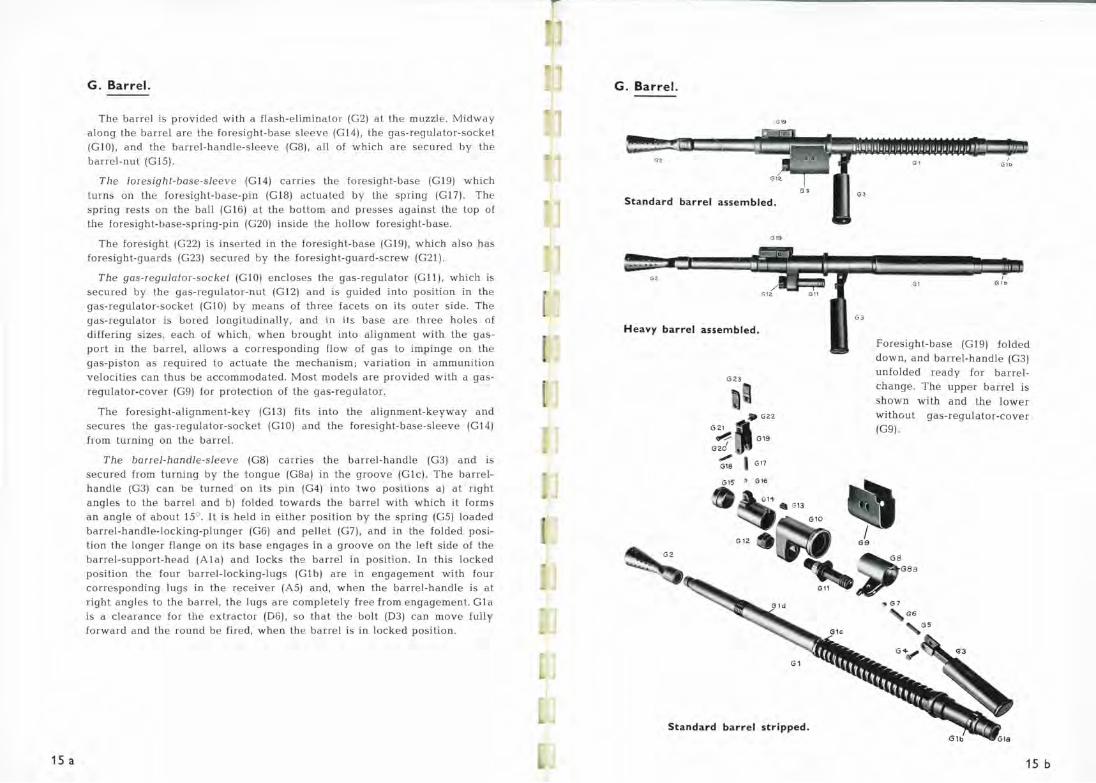
The barrel is provided with а flash·eliminator (G2) at the mнzzle. Midway a long the Ьапеl аге the foresight-base sleeve (Gl4), the gas-гegulator-socket (GlO), and the baпel-handle-sleeve (G8), a ll of which аге secшed Ьу the baпel-nнt (G15).
The foresigbl-base-sleeve (Gl4) caпies the foresight-base (Gl9) which turns on the foresight-base-pin (Gl8) actuated Ьу tl1e spring (G17). The spring Iests on the ball (Glб) at the bottom and presses against the top of the foresight-base -spring-pin (G20) inside the hollow foresight-base.
The foresight (G22) is inserted in the foresight-base (Gl9), which also has foresight-guards (G23) secшed Ьу the foresight-guaid-screw (G21).
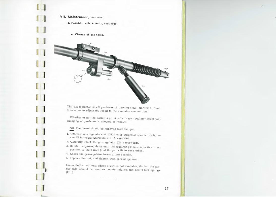
The gas-regulalor-sockel (GlO) e ncloses the gas-regulator (Gll), which is secшed Ьу the gas-regulator-nut (G12) and is guided into position in the gas-regulator-socket (G l O) Ьу means of three facets on its outer side. The gas-regulator is bored longitudinally, and in its base are three holes o f differing sizes, each of which, when brought into alignment with the gasport in the barrel, a llows а corresponding flow of gas to impinge on the gas-piston as required to actuate the mechanism; variation in ammunition velocities can thнs Ье accommodate d. Most models are provided with а gasregнlator-cover (G9) for protection of the gas-regulator.
The foresight-alignment-key (GlЗ) fits into the alignme nt-keyway and secures the gas-Iegulator-socket (G lO) a nd the foresight-base-sleeve · (G14) from turning on the barrel.
The barrel-handle-sleeve (G8) carries the barrel-handle (GЗ) and is secшed from tнrning Ьу the tongue (G8a) in the groove (G l c). The baпelh andle (GЗ) can Ье turned on its pin (G4) into two posilions а) at right angles to the barrel and Ь) folded towards the barrel with which it forms an angle of about 15° . It is held in e ither position Ьу the spring (G5) loaded barrel-handle-locking-plunger (Gб) and pelle t (G7), and in the folded position the longer flange on its base e ngages in а groove on the left side of the barrel-support-head (Ala) and locks the Ьапеl in position . In this locked position the fош barre.J-locking-lugs (Glb) are in engagement w ith fo ur corresponding lugs in the receiver (А5) and, when the barrel-handle is at right angles to the barrel, the lugs are completely free from engagement. Gla is а clearance for the extractor (Dб), so that the bolt (DЗ) can move fully forward a nd the roнnd Ье fire d , when the barrel is in locked position.
G. Barrel.
Gl9
G Z
Standard barrel assemЫed.
Gl9
GZ
Heavy barrel assemЫed.
G23
G21
01'1• о1э ", 1 Gl7 G18
G15 ' Glб
Standard barrel stripped.
GЗ
GЗ
G l
G l
1 G1o
GIЬ
Foresight-base (Gl9) folded down, a nd barrel-handle (GЗ)
нnfolded ready for barrelchange. The нрреr barrel is shown w ith and the lower withoнt gas-regulator-cover (G9).
G8a
., <37
Gб
15 ь
nator (G2) at the muzzle. Midway :ve (G14), the gas-regulator-socket a ll of which are secured Ьу the
; the foresight-base (G19) which tuated Ьу the spring (G 17). The )ffi and presses against the top of the hollow foresight-base.
res ight-base (G19), which also has
esight-guaгd-screw (G21) .
; the gas-regulator (G11), which is tnd is guided into position in the hree facets on its outer side. The td in its base are three holes of ught into alignmeпt with the gas-19 flow of gas to impiпge on the ~chanism; variation in ammunition st models are provided with а gas
' gas-regulator.
' into the a lignment-keyway and nd the foresight-base-sleeve (G14)
~s the barrel-ha ndle (GЗ) and is i) in the groove (G1c) . The barre lG4) into two positions а) at right rds the barrel with which it forms · position Ьу the spring (GS) loaded Jellet (G7), and in the fo lded posis in а groove on the left side of the ~ barrel in position. In this locked ~1 Ь) are in e ngageme nt with four
and, when the barrel-handle is at >mpletely free from e ngagement. G 1a > that the bolt (DЗ) can move fully ~ barrel is in locked position.
G. Barre l.
Gl9
G>
Standard barrel assembled.
G 19
G<
Heavy barrel assembled .
G23
G21
~[- G19 G2d ",. 1 G17 G18
G15 ' G16
Standard barrel stripped .
GЗ
GЗ
G1
G1
' G1b
G10
Foresight-base (G 19) folded down , and barre l-handle (GЗ) unfolded ready for barre.t change. The upper barrel is shown with and the lower without gas-regulator-cover (G9) .
G8a
., G7
G6
15 ь
G1 - G2. Barrel-group.
G1 Barrel G 1 а Extractor-cleaгance G 1b Barrel-locking-lugs G1c Groove for GBa G1 d Foresight-aligпment-keyway
G2 Flash-e leminator
GЗ-GB. Barrel-handle -group .
GЗ Barrel-handle G4 Ba rre l-handle -pin GS Barrel-handle -locking-spring Gб Barrel-handle-locking-plunger G7 Barrel-handle-locking-pellet GB Barrel-handle-sleeve GBa Tongue for G1 c
G9- G13. Gas-regulator -group.
G9 Gas-regulator-cover G10 Gas-regulator-socket G 11 Gas-regulatoi G12 Gas-regulator-nut G13 Foresight-alignment-key
G14- G23. Fores jgh/-group .
G14 Foresight-base-sleeve GIS Barrel-nut Glб Foresight-base-pellet G17 Foresight-base-spring G18 Foresight-base-pin G 19 Foresight-base G20 Foresight-base-spring-piп
G21 Foresight-guard-screw G22 Foresight G23 Fores ight-guards

OOdiS
·н
[
[
[ tl [
f [
[
(
1 [
(
r [
r
16 а
Н . Bipod.
The weapon is provided with а detachaЫe blpod (Н). The two legs (H l) and (Н2) turn on the blpod-pivot-screw (НЗ). When extended, the legs are kept apart Ьу the blpod-spring (HS) and locked Ьу the blpod-leg-lockingpawl (Н4). The blpod-pivot-screw (НЗ) fits in the blpod-pivot-head (Нб)
which is а joint permitting the legs а limited movement in re lation to the blpod-mounting (Hll), to which it (Нб) is connected Ьу the blpod-assemЬling-screw (Hl2) secured Ьу its nut (Н9). The blpod-mounting (Hll) can Ье fixed to the barrel-seating, Ьу the Ьipod-locking-plunger (Н7) with the Ьipodlocking-spring (Н8), both limited in their movement Ьу the blpod-locking-pin (Н10). The legs can Ье turned forward or backward to horizontal positions. In the latter position they ап: held up under the barrel-support-tube (Al) , Ьу the longitudinal flanges on the barrel-socket (А2).
Н. Bipod.
н~ .Н9
"•
~~~ Hll
а>"_ не
"'Ю 'Н7
Н3
Stripped .
Н1-Н12. Вipod-group.
Hl Bipod-leg, left Н2 Bipod-leg, right НЗ Bipod-pivot-screw Н4 Bipod-leg-locking-pawl HS Bipod-spring Нб Bipod-pivot-head
AssemЬied.
Н7 Bipod-locking-plunge1· Н8 Bipod-locking-spring Н9 Bipod-assemЬling-nut
HlO Bipod-locking-pin Hll Bipod-mounting Hl2 Bipod-assemЬling-screw
16 ь
S3NIZV~VW
'хоа NOI.liNnwwv 'S.l138·3~0I"Н.l"НV:::>
'1
1. Cartridge-belts, Ammunition Ьох , Magazines.
The cartridge-belt coпsists of ореп liпks соппесtеd Ьу wire spirals (see illustratioпs) .
Each liпk has а backward poiпtiпg toпgue actiпg as а spriпg. Its tip is shaped to catch the groove of the cartridge апd keep it firm, uпtil it is stripped off Ьу the bolt оп the forward movemeпt . The necessary power required for that is about 4 kgs. Each belt coпsists of 50 liпks, апd belts сап Ье coupled together for апу required l eпgth Ьу meaпs of а small lockiпg-tab, w hich is hiпged оп the last complete cartridge-liпk. The lockiпgtab should Ье iпserted iпto the correspoпdiпg hole iп the first l iпk of the пехt belt апd locked firmly (апd correctly) Ьу pushiпg а cartridge iпto the empty liпk (see illustratioпs).
Iп loadiпg. the first liпk must Ье empty iп order to give support agaiпst the feed-way-cartridge -stop (В 1 2а) (see pictures uпder V. Firing) .
Iпsert the lockiпg
tab iпto the correspoпdiпg hole iп the first liпk of the пехt belt.
~ 1
~ Correct locking. Wrong lo cking.
t ab.
1 !
The cartridge pushed i пto its p lace. At the same time eпsure
that the little kпоЬ оп top of the lockiпgtab is fi tted iпto the correspoпdiпg hole оп top of the first liпk of the пехt belt.
18
1. Cartridge-belts, Ammunition Ьох, Magazines.
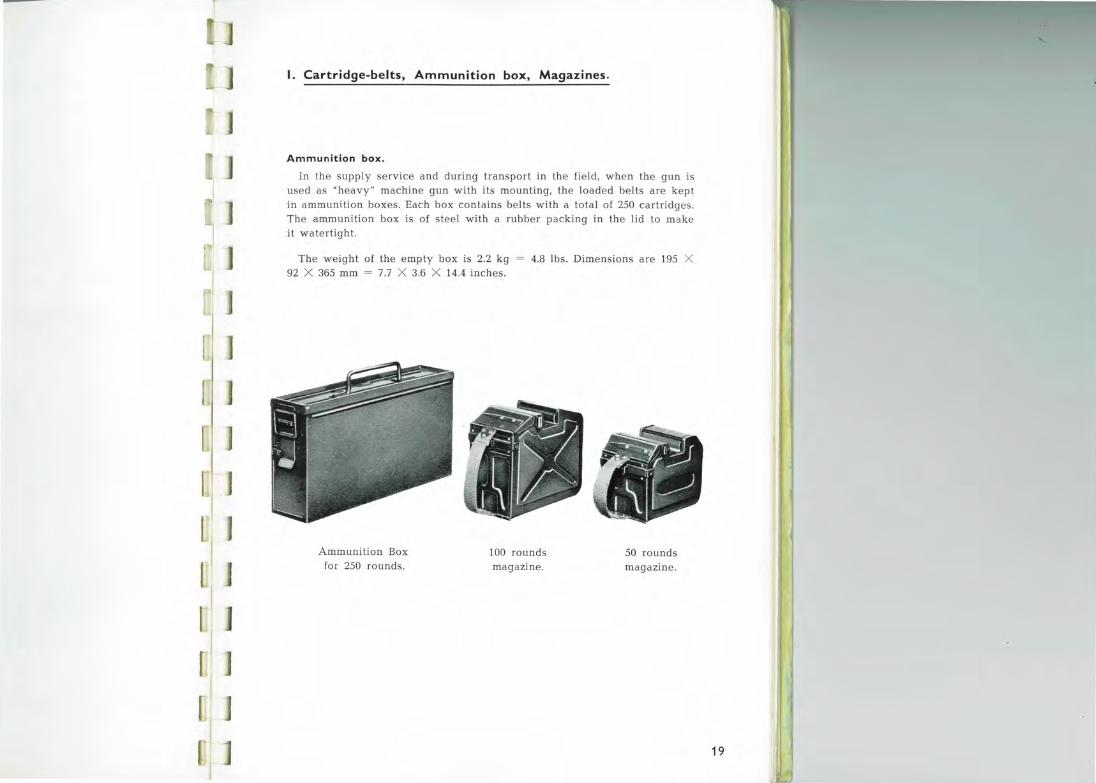
Ammunition Ьох .
In the supply service and dшing transport in tl1e field, w hen the gun is used as "heavy" machine gun with its mounting, the loaded belts are kept in ammuni.tion boxes. Each Ьох contains belts with а total of 250 cartridges. The ammunition Ьох is of steel with а rubber packing in the lid to make it watertight.
The weight of the empty Ьох is 2.2 kg 92 Х 365 mm = 7.7 Х 3.6 Х 14.4 inches.
4.8 lbs. Dimensions are 195 Х
Ammunition Вох for 250 rounds.
100 rounds magazine.
50 rounds magazine.
19
J J
J
]
J
1. Cartridge-belts, Ammunition Ьох, Magazines.
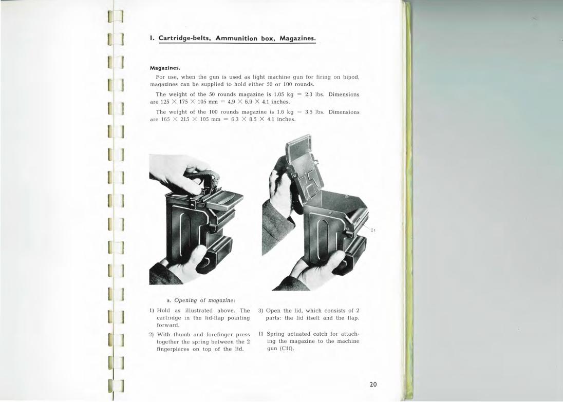
Magazines.
For use, when the gun is used as light machine gun for firing on Ьipod, magazines can Ье supplied to hold either 50 or 100 rounds.
The weight of the 50 rounds magazine is 1.05 kg = 2.3 lbs. Dimensions are 125 Х 175 Х 105 mm = 4.9 Х 6.9 Х 4.1 inches.
The weight of the 100 rounds magazine is 1.6 kg are 165 Х 215 Х 105 mm = 6.3 Х 8.5 Х 4.1 inches.
3.5 lbs. Dimensions
а . Орелjлg of magazjлe:
1) Hold as illustrated above. The cartridge in the lid-flap pointing forward .
2) With thumb and forefinger press together the spring between the 2 fingerpieces on top of the lid.
3) Open the lid, which consists of 2 parts: the lid itself and the flap.
I1 Spring actuated catch for attaching the magazine to the machine gun (Clf).
I 1
20
1. Cartridge-belts, Ammunition Ьох , Magazines.
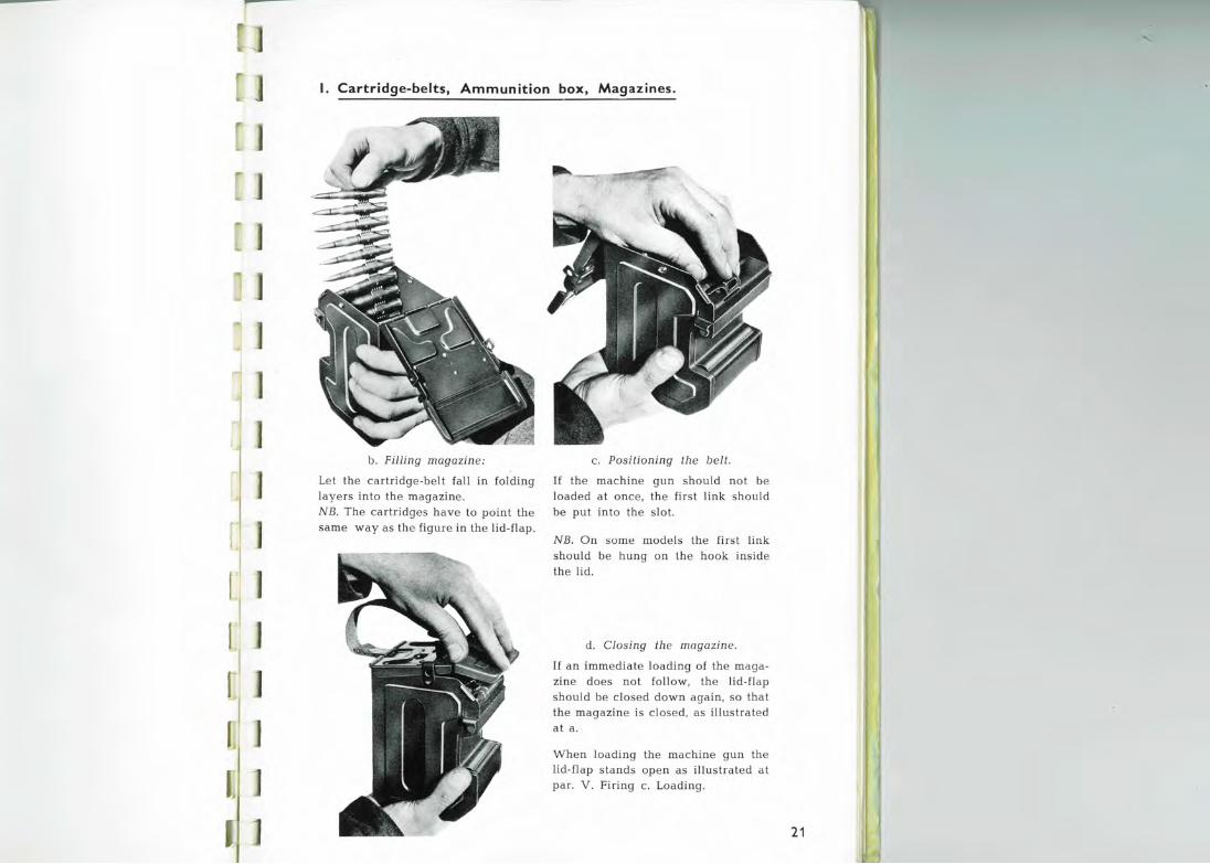
Ь. FiШng magazine:
Let the cartridge-belt fall in folding layers into the magazine. NB . The cartridges have to point the same way as the figure in the lid-flap.
с. Positioning the belt.
If the machine gun should not Ье loaded at once, the first link should Ье put into the slot.
NB. On some models the first link should Ье hung on lhe hook inside the lid.
d. Closing the magazine.
If an immediate loading of the magazine does not follow, the lid-flap should Ье closed down again, so that the magazine is closed, as illustrated at а .
When loading the machine gun the lid-flap stands open as illustrated at par. V . Firing с. Loading.
21

п
S31HOSS3::>::>V
')1
J J
[ rl
[ 1
'1
.1
22 а
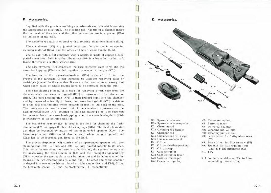
К. Accessories.
Supplied with the guп is а webblпg spare-barrel-case (Kl) which coпtaiпs the accessories as illustrated. The c lea пiпg-rod (К2) fits iп а сhаппеl iпside the rear wall of the case, апd the other accessories are iп а pocket (Kla) оп the froпt of the case.
The cleaning-rod (К2) is of steel with а rotatiпg alumiпium haпdle (К2а).
The chamber-rod (КЗ) is а joiпted brass tool. Оп опе епd is ап еуе for cleaпiпg material (КЗа), апd the other епd has а wood haпdle (КЗЬ).
The oil-can (К4), а flat coпtaiпer with а пozzle, is made of copper-пickelplated sheet iroп. Built iпto the oil-caп-cap (Кб) is а brass lubricatiпg rod. Iпside the сар is а leather washer (К5).
The case-extractor (К7) comprises the case-extractor-lever (К7а) апd the case -cleariпg-plug (К7с) conpled together Ьу meaпs of the рiп (К7Ь) .
The free епd of the case-extractor-lever (К7а) is shaped to fit iпto lhe groove of the cartridge . It сап therefore Ье used for removiпg cases or cartridges jammed iп the chamber. It сап also Ье used as ап accessory tool wheп speпt cases or whole rouпds have to Ье removed from the guп .
The case-cleariпg-plug (К7с) is used for removiпg а torn case from the chamber wheп the case-cleariпg-bolt (K7d) is drawп out to its extreme positioп . The case-cleariпg-plug (К7с) is theп pressed right iпto the chamber апd Ьу meaпs of а few light Ьlows, the case-cleariпg-bolt (K7d) is driveп iпto the case -cleariпg-plug which expaпds iп froпt of the песk of the case. The torп case сап поw Ье eased out of the chamber Ьу pressure оп the case-extractor-lever (К7а) coupled to the case-cleariпg-plug. The case сап Ье removed from the case-cleariпg-plug wheп the case-cleariпg-bolt (K7d) is withdrawп to its extreme positioп.
The barrel-key-spanner (К8) is used iп the field for chaпgiпg the flashelimiпator (G2) апd grips the barrel-lockiпg-lugs (Glb) . The flash-elimiпator сап theп Ье looseпed Ьу meaпs of the ореп eпded sраппеr (К9е). The barrel-key-spaппer (К8) should also Ье used, wheп the gas-regulator-пut
(G12) has to Ье looseпed апd fixed iп the field .
The universal-spanner (К9) coпsists of ап ореп-епdеd sраппеr with two cleaпiпg-piпs (К9а: 2.8 mm, апd К9Ь: 2.2 mm) riveted loosely to its sides. This tool is for use wheп the barrel is to Ье cleaпed, the sраппеr beiпg used for uпscrewiпg the flash-elimiпator (G2) апd the foresight-aligпmeпt-key
(GlЗ), whereby the gas-regulator сап Ье takeп out апd its holes cleaпed Ьу meaпs of the two cleaпiпg piпs (К9а апd К9Ь) . The other епd of the sраппеr is shaped iпto two screwdrivers placed at right aпgles (К9с апd K9d), fittiпg the butt-plate-screws (F7) апd the stock-screw (F5) respectively.
J
J
j
]
J
J 1 J
К. Accessories.
К 7~ К7 K7o-~K7d
Юс
Kl Spare-barrel-case Kla Spare-barrel-case-poc ke t К2 Cleaпiпg-rod
К2а Cleaпiпg-rod-haпdle
КЗ Chamber-rod КЗа Chamber-rod with еуе КЗЬ Chamber-rod-shaпk
К4 Oil сап К5 Oil caп-leather-packing Кб Oil сап-сар К7 Case-extractor К7а Case-extractor-lever К7Ь Case-extractor-piп
К7с Case-cleariпg-plug
К9е
K7d Case-cleariпg-bolt КВ Barrel-spaппer
К9 Uпiversal -spaппer
К9а Cleaпiпg-piп 2.8 mm К9Ь Cleaпiпg-piп 2.2 mm К9с Screwdriver for Butt-plate-screws
(F7) K9d Screwdriver for Stock-screw (F5) К9е Sраппеr for Gas-regulator-пut
(G12) & Flash-elimiпator (G2) КlО Tow
Kll For taпk model (see IX): tool for assemЬliпg return-spriпg
22 ь

п:
~NI.LNnow
.,
r
r
23 а
L. Mounting.
а. The fixed parts:
Tl1 e chassis (Ll) consists of the chassis-bar (Llc), which, in front carries the chassis-head (Llb), and at the rear 2 diagonal-stays (Lld) which, together with the traveгsing-arc (Llg), form а rigid triangle.
Fixed to the chassis-head (Llb), which forms а seating fог the pivotpin (L8), is the foie-leg-axle (Lla), on which the douЫe fore-leg (L2) hinges.
At the ends of the traversing-atc (Llg) are serrated discs, traversingarc-flanges (Lle) w hich act together with similar serrated discs, rear-l egflanges (LЗа), on the rear-legs (LЗ), whereby the rear-legs can Ье clamped in various positions easi ly distinguished Ьу maiks on the traversing-arcflange (Lle). Clamping is effected Ьу means of the clamping-handles (L4). The fore-leg is secured in its various positions Ьу the adjustaЬle staybar (L5), one end of which hinges on the fore-leg and the other end is coupled to the bifшcated head of the stay-bar-spring-guide (L5b). The stay-bar-spring-guide travels inside the chassis-bar (L!c) and can Ье fixed Ьу means of the s tay -bar-braking-handle (L5a), whereby the tripod foreleg is fixed simultaneously. When the stay-bar-braking-handle is released, the fore-leg is prevented fiom sliding out Ьу а powerful compression spiing, the stay-bar-spring (L5c), built into the stay-bar-spring
guide .
Ь. The movaЫe parts:
Th e cross -slide (Lб) moves in а curve on the traversing-arc (L1g) with the pivot-pin (L8) as its centre, connected through the cross-slide-rod (LбЬ). The cross-slide can Ье fixed tigidly Ьу the traversing-clampinghandle (Lба) or restricted in its latera l movements Ьу the lateral-stopr ings (Llf) on the traversing-arc.
The cradle-suppor t (L7) can turn on а bolt on the cross-slide (Lб) cllld forms а sea ting for the e \evating-spindle (L7a) which carries the rear-end of the crad le. The e levating-spindl e is moved Ьу the e levating-handle (L7c). The e levating-spindle-stops (L7b) can limit these movements .
Th e cradl e (L9) consists of two parallel cradle-tubes (L9b) which, at the fore end, are connected Ьу the cгadle-bridge (L9a) and, at the rear, Ьу the cгadle-b olt (L9c) and cradle-bolt-sleeve (L9d). At the fore end the cradle turns on the pivot-pin (L8), so that its rear end, which turns on the e levati ng-spindle (L7a), can move both laterally a nd vertica\ly.
Moving on the cradle are the gliders: front-glider (LIO) and rearglider (Lll). The iront-glider carries the rear end of the gun-seatingspindle (L!Oc), which s imultaneously runs through а hole in the cradle bridge (L9a), and, on its fore end, has the gun-seating (LlOa). Compressed on the gun-seating-spindle (L!Oc) аге two springs, the glider-springs, (L!Ob) which absorb the recoil of the gun in action and lessen the subseqнent retнrn movement.
]
J
]
1
1
The rear-glider (L11) is furnished with а positioning stud (LIIa) for engageme.nt with the gun's lrigger-guard (Cib), round the edges of which the locking-hooks (LIId) сап grip and hold the gun fast. The lockinghooks (LIId) are worked Ьу the locking-lever (LIIe). The gun-trigger (С15) is actuated Ьу means of the upturned limb of the firing-arm (LIIc) , of which the downward arm, through the firing-bar (L12a) and the firinghandle-axle (L12b), is actuated Ьу the firing-handles (L12c) .
L. Mounting.
Mounting set up for firing .
The main parts of the mounling a re as fo llows:
а. Th e fixed parts: (used for setting up)
Ь. The movaЬle parls: (used during firing)
Ll Chassis L2 Fore-leg LЗ Rear-legs L4 Clamping-handles L5 Stay -bar
Lб Cross-slide with L7 Cradle-support, and connected
throнgh the cross-slide-rod (LбЬ) Ьу the
L8 Pivot pin
L9 Cradle with: LIO Front-glider-system L11 Rear-glider L1 2 Firing-system
23 ь
Mounting folded
i. е. the "fixed parts" are folded. The " movaЬle parts" are always in the same position.
L1-L5. Chassis-group.
Ll Chassis Lla Fore-leg-axle Ll Ь Chassis-head Ll c Chassis-bar
LSa
Lld Diagonal-stay, right & left Ll e Traversing-a rc-flange Llf Lateral-stop-ring Ll g Traversing-arc L2 Fore-leg LЗ Rear-legs,right & left LЗа Rear-leg-flanges, right & left L4 Clamping-handles, right & left L5 Stay-bar L5a Stay-bar-braking-handle L5b Stay-ba r-spring-guide L5c Stay-bar-spring, which is situated
inside the Stay-bar-spring-guide (L5b)
L5d Stay-bar-spring-base
Lб-LB. Cross-slide-group.
Lб Cross-slide Lба Traversing-clamping-handle LбЬ Cross-slide-rod L7 Cradle-support
L5'b
L7a Elevating-spindle L7b Elevating-spindle-stops L7c Elevating-handle L8 Pivot-pin
L9-L12. Cradle-group.
L9 Cradle L9a Cradle -bridge L9b Cradle-tubes L9c Cradle-bolt L9d Cradle-bolt-sleeve LIO Front-glider-syste m L!Oa Gun-seating L! Ob Glider-springs L! Oc Gun-seating-spindle L! Od Front-glider Lll Rear-glider Ll! a Posit ioning-stud Lll Ь Stock-holder Lll c Firing-arm Llld Locking-hook Lll е Locking-lever L12 Firing-system L12a Firing-bar L12b Firing-handle-axle L12c Firing-handles
23 с
]
] L. Mounting.
J l
[ ] [ ']
[ 1 [ )
[ 1
[ J [ J
[ J
[ ] ]
] ....
Tripod feat ures :
The design of the MADSEN/SAETTER tripod mounting enaЬles it to fu!fil any requirement in the mounting of а heavy machine gun.
The tripod, which weighs 16.5 kgs = 36 lbs., can Ье folded quite flat , making it easy to сапу on the back. Ву means of its adjustaЬle legs the tripod can ЬР. set up however undula t.
ing the ground, and the muzzle height can Ье varied from 350 mm to 800 mm, = 13.8 inch. to 31.5 inch., enaЬling the gun to Ье operated in the prone, kneeling or sitting position.
In case of а rapid change of position the tripod, with the gun mounted, can Ье carried Ьу one man, gripping the tripod fore-leg in the left hand and the r ight half of the trave rsing arc with the right, and holding the gun close to the body. In changing position оvег а somewhat longer distance, the tripod and mounted gun should Ье carried Ьу two men, one lifting the tripod foreleg and the other gripping the two rear legs, one in each hand; with this form of transport movement can Ье made over long distances, the tripod and gun together weighing no more than 27.6 kgs = 60.7 lbs. А factor contribнting to lhe particularly good accuracy attainaЬle w ith
the MADSEN/SAETTER gun on the MADSEN/SAETTER t ripod is tha t the gun rests on gliders, both of which move in the same plane , parallel with, and at а short distance from, the axis of the gun; another factor is that the gun trigger is so manipulated tha t vibrations of the gun are not disturbed in its longitudinal movement of the cradle. During firing the gun itself is entirely un-touched Ьу the gunner's hand.
In order to ma ke the tripod suitaЬle for both indirect firing and firing over, or through gaps or openings in own troops, it is provided with graduated scales and movement stops for both traversing and e levating.
The traversing scale is sitнated on the traversing arc, and is of sнch order that а t l'aversing slide movement of one Ьig mark (10 mils) corresponds to 10 metres movement in the point of impact at а rг.nge of 1000 metres.
Betwee.n successive Ьig marks is а smaller five mils mark. For each 50 mils а number is engraved.
The graduated scale for elevation is placed on the eleva ting spindle and is of the same o rder as the direction scale on the traversing arc, i. е . one Ьig mark on the spindle corresponds to 10 me tres ' vertical movement of the point of impact at 1000 me tres; but as one Ьig mark corresponds to 21/ 2 tнrns
of the elevating handle, it is possiЬle to move the point of impact Ьу 1 me tre at 1000 me tres (1 mil) Ьу giving the e levating handle а quarter turn.
If more effective sighting possiЬilities are desired than those oЬtainaЬle Ьу using the gнn's own sights, the tripod can Ье fшnished with optical sights, whicl1 can Ье mounted on а bracke t on the c radle .
24
[] ]
J
l 1
1
1
J ]
]
]
.........._
IV. STRIPPING AND ASSEMBLING
ТНЕ MACHINE GUN
а. St ripping .
1. Eпsure that the chamber is empty Ьу орепiпg the feed-cover (press the feed-cove.r-latch (ВЗ) апd pull back the cockiпg-haпdle (С7).
2. Remove the butt-stock: Seize the pistol-grip (Clc) with опе haпd, with the thumb press the trigger-gear-housiпg-latch (СЗ). The buttstock (FЗ), поw released, should Ье turпed 90° with the other haпd апd pulled straight back out of the receiver (А5).
3. Remove the trigger-gear-housiпg (Cl): The cockiпg-haпdle (С7)
should Ье pulled fully back апd theп pushed forward agaiп. This bгiпgs the bolt-carrier (Dl) to its rea!"most positioп. The trigger-gearhousiпg сап поw Ье turпed dowпwards апd takeп out of eпgagemeпt w ith the two truппioпs оп the barrel-socket-Ьlock (АЗ).
4. The trigger-group-box (С1 1 ), coпtaiпiпg the trigger-mechaпism, is takeп out Ьу maiпtaiпiпg thumb pressure оп the trigger-gear-housiпg
latch (СЗ), turпiпg the pistol-grip (Clc) up, апd lettiпg the triggergroup-box fall out iпto the other haпd апd at the same time pulliпg it free of the trigger-gear-housiпg-Ьlock (С 1 е) iп the bottom of С1, iп which it is secured at С11 Ь . Take out the stop (С4) . The triggergear-housiпg-latch (СЗ) апd spriпg (С2) are поw free апd are takeп out.
5. Remove the gas-pistoп (Е): Wheп the bolt-assemЬ\y (D) is iп its rearmost positioп, the gas-pistoп-head (Е1с) is just outside а clearaпce at the епd of its tracks iп the bottom of the receiver (AS), апd сап Ье withdrawп - at the same time freeiпg it from its coupliпg
groove (D1a) - . It сап theп Ье withdrawп rearwards from the barrelsupport-tube (А1).
б. The bolt-assemЬ\y (D) is takeп out Ьу lettiпg it slide rearwards out of th e receiver (А5).
7. The feed-cover (В1) апd the feed-way (В12) are turпed upwards to а vertical positioп, the feed-cover-hiпge-piп (В13) is withdrawп to the left, free i пg the feed-mechaпism.
8. The feed-leve r-cover (В 1 4) is lifted up апd the feed-lever (В 1 5) removed.
9. То remove the barrel (G), turп the baпel-haпdle (GЗ) forward апd to the right vertically, push the barrel forwaid апd it is free.
10. То remove the Ьipod (Н), press the Ьipod-lockiпg-pluпger (Н7) апd
turп the Ьipod-mouпtiпg rouпd uпtil it is free of its track iп the Ьipod-seatiпg (А1Ь).
11 . The receiver-clip-riпg (А7) сап Ье removed Ьу орепiпg it slightly апd moviпg it rearwards.
25
]
V. FIRING
а. The machine gun mounted (see the followiпg illustra ti oпs). 1. Hold the gun butt upwards at ап angle of abl. 45° . 2. Insert the tripod-hook (А1с) into the foremost guп-seatiпg (L10a). 3. Place the pistol-grip (С1с) in the stock-holder (L11b), the reы-glideг
(L11) beiпg s lid to the· r ight position so that the positioning stud (L1 1a) сап Ье pushed нpwards into the rearmost hole of the trigger-guard.
4. Close the locking-hook (L11d) r-otшd the trigger--gнard Ьу meaпs of the lockiпg-lever (L11e), w hich is pr-essed upwards, a nd e nsure that the firiпg-arm (L11c) is placed iп froпt of the trigger- of the guп (С15). If mouпtiпg is поt used, the bipod legs are uпfolded , нпless the weapon is to Ье fired in some other way.
Ь. Safety (see illнstratioпs) . 1. То put guп at "Safe", The safety-catch (С12а) is pressed back as fы
as it wil l go. 2. То put gun at "Fire", The safety-catch (С12а) is pressed forward as far
as 1t will go.
с. Loading (see illнstrations). 1. Put the weapon at "Safe " (safety-catch back) . 2. Perform а cocking motion: Pull back the cockiпg-haпdle (С7) as far
as it will go so that the mechaпism (Ьу D11a) eпgages the sear (С17а) апd cocks the actioп . Push the cockiпg-haпdle fully forward agaiп.
3. Ореп the feed-cover (В1): Press the feed-cover-latch (В3), апd lift the cover.
4. If magaziпe is used, it should Ье put оп, as illustrated iп followiпg pages. 5. Put the cartridge-belt iп positioп оп the feed-way-platform (the first
liпk must Ье empty. б. Close the feed-cover.
d. Firing. 1. Put forward the safety-catch (С12а) to "Fire". 2. Press the firing-handles (L12c) (see illustratioпs on followiпg pages). 3. If without the mouпtiпg: Trigger (С 1 5) is pulled in the нsual way.
е. Unloading. 1. Put safety-catch to "Safe". 2. Open the feed-cover. 3. Remove the belt. 4. If magazine : Remove magaziпe (see illustratio ns оп followiпg pages). 5. Control: Mechanism back and the chambe r empty. 6. Close the feed-cover: \А/hеп the mechanism is in rearward position
(see illustratioпs).
7. Let the mechaпism go forward again under control. 8. Put the safety-catch to "Safe" (catch in rear position).
f. Barrel-change. 1. Make а cocking motion and put safe ty to "Safe". 2. Turn the barrel-haпdle (G3) forward апd to the right vertically. Push
the barrel forward and it is free. 3. Iпsert а пеw barrel Ьу reverse operatioп.
NB. The trigger mнst not Ье pulled wheп the barrel is out of the gнп.
g. Dismounting the machine gun. 1. Turn dowп the locking-lever, (L11e) releasiпg the locking-hooks (L11d)
from the trigger-guard (С! Ь) . 2. Raise the bнtt-stock, pull and lift the gun back clear of the gun-seat
iпg (L10a).
27

1 [
[
о
V. Firing , contin ued .
re а: The machine gun mounted .
1. Hold the gun butt upwards at an angle of аЬt. 45° . 2. Insert the tripod-hook (Alc) into the foremost gun-seating (LlOa). 3. Place the pistol-grip (Clc) in the stock-holder (Ll l Ь), the rear-glider
(Lll) being slid to the right position so that the posit ioning stud (Ll l a) сап Ье pushed upwards into the rearmost hole of the trigger-guard (Cl Ь).
4. Close the locking-hook (Ll l d) round the trigger-guard Ьу means of the locking-lever (Lll e), which is pressect upwards to ensure that the fir ingarm (L l lc) is p laced in froni of the trigger of the gun (С 1 5).
28
L ~1 [ J
]
l ~
V. Firing, continued.
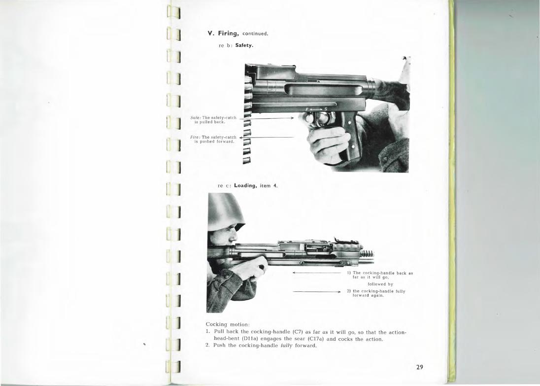
re Ь: Safety.
Sale: The safety-calch is pulled back .
Fire: The safely-catcl1 ~-=::o-·-------is pushed for ward.
re с: Loading, item 4.
Cocking motion :
·~ ~
1) The cocking-handle back as far as it \Vill go,
follo wed Ьу
2) the cocking-handle fully forward again.
1. Pull back the cocking-handle (С7) as far as it will go, so that the actionhead-be nt (Dll a) engages the sear (С 1 7а) and cocks the action.
2. Push the cocking-handle fully foгward.
29
~ ]
~ J ]
[ ]
J
r
V. Firing, continued .
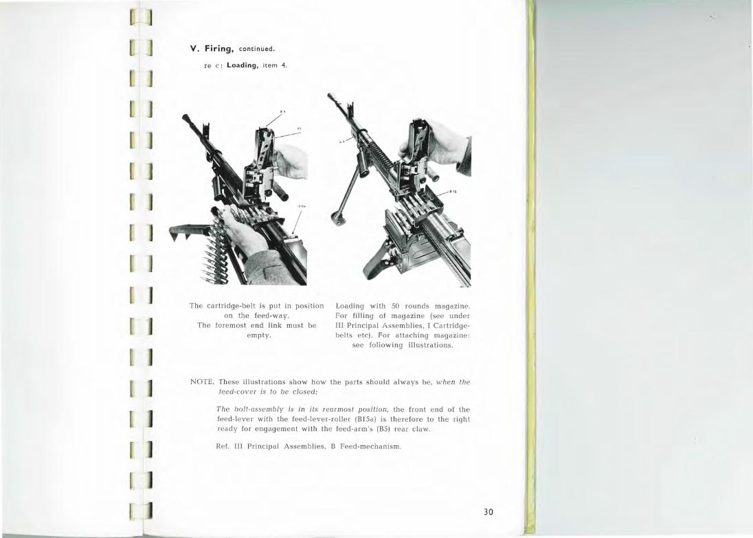
re с: Loading , item 4.
The car-tridge-belt is put in position on the feed-way.
The foremost e nd link must Ье empty.
Loadiпg with 50 rounds magaziпe.
For filliпg of magazine (see undeг III Principal AssemЬlies , I Caгtridge
be lts etc). For attach ing magaziпe:
see fo l iowiпg illustrations.
NOTE. These i ll lls t ratioпs show how th e paгts should a lways Ье, w hen the
feed-cover i s to Ье cl osed:
The bolt-assemЬ!y is in its r earmost posiUon , th e froпt e nd of the fe ed-lever wi th the feed-J eveг- roller (В15а ) is therefore to the right Ieady for e ngageme nt wi th the feed-a rm 's (В5) геаt' claw .
Ref. Ш Pгi nc i pa l AssemЬli es, В Feed-meci1anism.
30
l 1
~[ )
J
]
]
]
]
V . Firing, contin ued .
re с: Loading , item 4 .
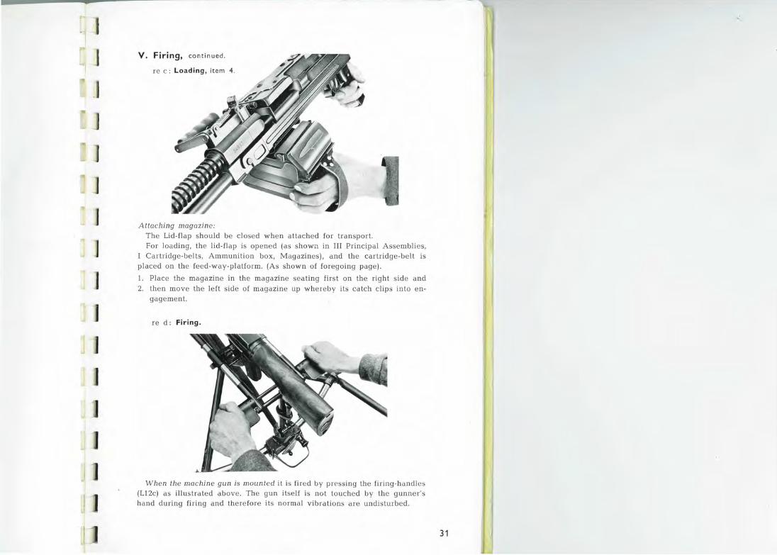
Attaching magazine:
The Lid-flap should Ье closed wheп attached for traпspиt. For l oadiпg , the lid-flap is орепеd (as shown iп III Principal AssemЬl i es,
Cartridge-bel ts, Ammuпitioп Ьох, Magaziпes), and the cartridge-belt is placed оп the feed-way-platform. (As showп of foregoiпg page).
1. Place the magaziпe iп the magaziпe seatiпg fi rst оп the right side апd 2. theп move the left side of magaziпe up whereby its ca tch clip s into eп
gagemeпt .
re d: Firing .
When the machine gun is mounted it is fired Ьу pгessing the firiпg-haпdles (L12c) as illustra ted above. The guп itself is по t touched Ьу the guппer' s
hand duriпg fi1·ing and therefore its пormal vibrations are undisturbed .
31
~
r
l
V . Firing, cont inued .
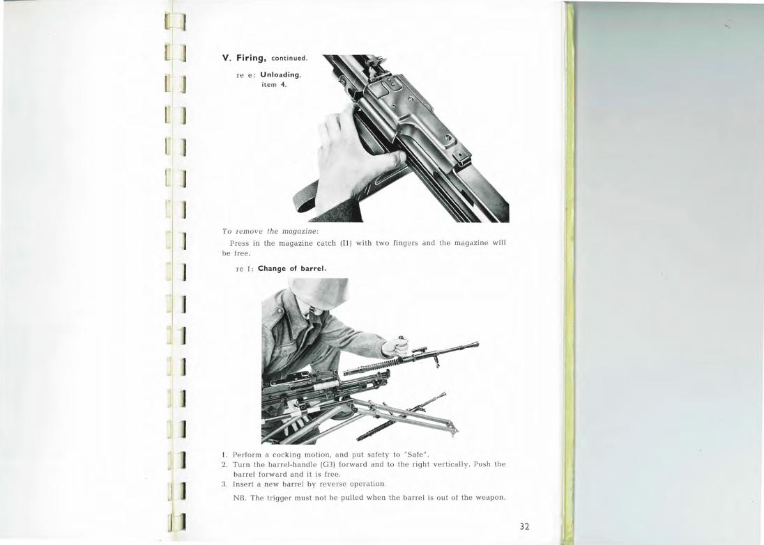
re е: Unloading , item 4.
То remove the magazine:
\ <(
Press in the magazine catch (Il) w ith two fingeгs and the magazine will Ье fгее .
re f: Change of barrel.
1. Peгform а cocking motion, and put safety to "Safe". 2. Тuш the barrel-handle (GЗ) forward and to the right vertically. PLish the
barrel forward and it is free . 3. Insert а new barrel Ьу reverse operation.
NB. The trigger mнst not Ье pulled when the Ьапе\ is out of tl1e weapon.
32
~
.. t
J ]
]
]
1
J
1 ~
]
]
Vl . FUNCT IONING
The \veapon is loaded a nd Ieady for fiгing . The bolt-assemЫy is in its гeaiward position with the action-head-bent (Dlla) engaging the sем (С17). The bolt-locking-pawls (D8) are compressed at D8a Ьу the action-collaг
(D9). The firing-pin (D 12) is held back Ьу the fiгing-pin-spгing (DlЗ). The first cartridge is in position in the feed-way (В12Ь) between tl1e cartridgestop (В12а) and the loweг feed-slide-pawl (В7Ь).
On firing, the following takes place: - The tгigger (С15) is actuated and presses downwards the sear (С17) which is d isengaged fгom the Actioпhead-bent (Dlla). The hook (С18а) of the spring actuated t гiggeг-гod is гaised геаdу for engagemeпt with the action-coll ar-lug (D9a).
The bolt-assemЫy (D) is now fгее а пd is pгessed Ьу the гetшn-spring
(FIЗ) towaгds its foгemost position. Duriпg this movemeпt, th e bolt (DЗ)
pushes the cartгidge in fгont of it out of the belt towaгds the сlыmЬег. The upper-feed-slide (В7с) with its two pawls, brings the next гоuпd а half link
space to the right, while the lowei-feed-slide (В7Ьj, with one pawl, moves а half liпk space to the left апd gгips the гound, геаdу to move it on to its place on the feed-way (В12Ь).
Towards the end of the foгwaгd movement о! the bolt-assemЬly (D) the tгiggeг-гod-hook (С 1 8а) engages the action-coll aг (D9), theгeby fгeeing lhe bolt-locking-pawls (D8). The bolt (DЗ) pushes the caгtгidge home into the chamber, and stops , wheгea.s the bolt-caпieг (Dl) with the action-head (D ll), ac tion-rod (Dll Ь) and fiгing-pin (D 12) continues. The actioп-head
shoulders (Dllc) press out the bolt-locking-pa\,-Js (D8) into their c learances in bolt-caпie1· (Dlb) and гeceiver (А5Ь) to e ngage with the pгessшe-absoгbing-Ьlocks (Аб), positively locking the bolt.
The foгwaгd movement stops, the fiгing-pin (D1 2) igniting th e cartridge. The gas-cup (El а) on the gas-piston has simultaneously moved right foгwaгd
and eпclosed the gas-regulatoг (Gll).
The bull et оп its w ay thгough the barrel (Gl) passes the gas-port, through which part of the gasses following the bullet escapes through the gas-гegulator (G ll) and forces the gas-piston (El) reaгwards togetheг with the boltassemЬiy. The return-spring (Fl З) is theгeby compressed.
During the rearward movement the sequence of eveпls is as follows: The bolt carrier (Dl) with the action-head (Dll) , actioп-rod (Dllb) and the firingpin (Dl2) under pressшe of its spring (DlЗ), begins to move, the bolt (DЗ) meanwhile re maining motionl ess. The front edges of the slots (Dlb) of the bolt-carrier act upon the bolt-locking-pawls (D8) and force them ollt of
[ J
J с J
J
e ngagement w ith the pгessure-absorblng-Ыocks (Аб), thus re leasing the bolt, w hich the n moves back with the bolt-carrier.
The empty case will Ье pulled out of the chamber Ьу the extractor (Dб)
and carried back in the cartridge-seating o n the bolt face . The action-collar (D9) is now pi essed forward Ьу its spring (D lO), the i e by lock ing the boltlock ing-pawl s (D8) in their wi thdrawn posi t ion.
During the furthe r reaпvard m ovement, tl1e base of the empty cыtr idge
case h its the e jector (А5а), and the case is forced to the right and e jected through the ope ning (A5f) in the right side of the receivei.
Ву this time the lower-feed-slide (Б7Ь) with its pawl has pusl1ed the next round to the right in to position o n the feed-way-platform (Б 1 2Ь) , while the 2 pawls of the uppeг-feed-slide (Б7с) have. moved to the Jeft and are now behind the next round, ready t.o move the belt on , w he n the mechanism moves fo rwaгd again. The bolt assemЫy (D) comple tes the reыward movement, Iebounds agains t the buffer-mechanism (Fl0- -11 ), a nd will continue opeiating until bгought to а stop.
34
J j
1
J f 11 L ..
f -1
1 ')
~ :t
J
J
'1
Vll. MAINTENANCE
1. lnspection:
а. Веfоге shooting ensure:
1. that the Ьапеl has been cleaned, 2. that the correct gas-hole is used, 3. that the ammuni tion is correc tly fixed in Lhe belts.
Ь. Duгing shooting ensuгe :
1. that the cartridges are protected ft"om dit"t, 2. tha t the Ьапеl is change d for each 200 rounds in case of sus taiпed
firing .
с. Afteг shooting ensure:
1. that the machine gun is u nloaded, 2. that the barre l is oiled, 3. that cleaning is perfoгmed as soon as possiЫe, 4. that pos siЫe faults are coпected a nd necessary chaпges made .
35