Embed Size (px)
Citation preview
Mikołaj SPADŁO, Dominik DEMBICKI, Paweł WOŹNIAK, Jan Szczepaniak „Journal of Research and Applications in Agricultural Engineering” 2016, Vol. 61(2) 97
Mikołaj SPADŁO, Dominik DEMBICKI, Paweł WO ŹNIAK, Jan SZCZEPANIAK Przemysłowy Instytut Maszyn Rolniczych ul. Starołęcka 31, 60-963 Poznań, Poland e-mail: [email protected] STRENGTH ANALYSIS BY METHOD OF THE FINITE ELEMENTS IN CONSTRUCTION
OF SPRAY STERILIZER WITH RESTRICTIONS OF STANDARD E N 13445-3
Summary
The article describes the problem of stress analysis in spray sterilizers according to EN 13445-3, widely used in the food industry. Operating conditions of the test device were characterized and a method of design verification using FEM was de-fined. Conditions of computer implementation research were determined and choice of a methods for assessing sterilizer was made, based on stress analysis. It was found a criterial stress for material of which the vessel is made. The maps of characteristic stress was generated, the areas of concentration was localized and confronted the results of set limits. More-over, the fatigue life of welds and base material were estimated. As a result, an effort of the state system was determined. It was found that the structure is characterized by level of safety, which allows to build a prototype for validation of numeri-cal model by strain gauge methods. Key words: pressure vessel, standards EN 13445-3, fatigue research, FEM
ANALIZA WYTRZYMAŁO ŚCIOWA METOD Ą ELEMENTÓW SKO ŃCZONYCH KONSTRUKCJI STERYLIZATORA NATRYSKOWEGO Z ZASTOSOWAN IEM
OBOSTRZEŃ NORMY EN 13445-3
Streszczenie
W artykule opisano problematykę analiz wytrzymałościowych sterylizatorów natryskowych według normy EN 13445-3, sze-roko stosowanych w przemyśle spożywczym. Scharakteryzowano warunki eksploatacyjne badanego urządzenia i określono metodę weryfikacji konstrukcji z użyciem MES. Wytyczono warunki realizacji komputerowych badań i dokonano wyboru metod oceny sterylizatora bazujących na analizie naprężeń. Ustalono naprężenia kryterialne dla materiału, z którego zbu-dowany jest zbiornik. Wygenerowano mapy naprężeń charakterystycznych, zlokalizowano obszary koncentracji i skonfron-towano wyniki badań z przyjętymi limitami. Przeprowadzono ponadto szacowanie trwałości zmęczeniowej spoin i materiału rodzimego. W efekcie ustalono stan wytężenia ustroju. Stwierdzono, iż konstrukcja charakteryzuje się poziomem bezpieczeń-stwa umożliwiającym zbudowanie prototypu dla potrzeb walidacji modelu numerycznego metodami tensometrycznymi. Słowa kluczowe: zbiornik ciśnieniowy, norma EN 13445-3, badania zmęczeniowe, MES 1. Introduction The sterilization process is one of the key steps in the food processing industry. It consists in an intensive thermal impact on the food product in a relatively short time (an-nealing step takes on average 15 to 30 minutes). Steam or hot water is usually a working medium. It can distinguish basically two temperature ranges of process, ie. 115 to 121°C and 130 to 145°C. Selection of appropriate process parameters are determined by processed food product. A consolidation of food through destroying all microorgan-isms and their form of survival structures is the result of properly conducted sterilization process [1, 6]. To successfully carry out the process of sterilization of food products, while reducing energy inputs, applies an in-creased pressure within the working chamber. By increas-ing the pressure an increase of enthalpy in used working medium is achieved. That results also in an increased ther-modynamic potential of the system which is capable of more intense heat exchange with the sterilized product. Described process in industrial applications is carried out usually using spray sterilizers [6]. The working cham-ber of these devices is a thin-walled pressure of vessel armed with the supply system of working medium and proper control and measurement equipment. The process of
loading and unloading of batch units is carried out by the cover (blind system is equipped with a cap assembly, and the passage arrangement with two cover bands on both sides of sterilizer). The pressure used in the spray sterilizer is usually from 2 to 4 bar, in which a steam is used as the working medium [6]. Having regard to the specifics of the work sterilizer, which is subjected to cyclic changes of temperature and pressure and loaded with cargo, strength analysis process of its construction requires a specific approach. The subject of studies described later in this article in-cludes spray sterilizer execution on four baskets of flow system ie. loading and unloading takes place on opposite sides of the work chamber (fig. 1). Verification of safety level in sterilizer construction was based on analysis using the Finite Element Method. Due to the fact that the developed sterilizer construction is a very responsible technical object, working under considerable pressure, it was decided that the preparation of computa-tional model, the relevant calculation and assessment of re-sults will take place in accordance with the standard EN 13445-3: 2014-11 Unfired pressure vessels - Part 3: Design.

Mikołaj SPADŁO, Dominik DEMBICKI, Paweł WOŹNIAK, Jan Szczepaniak „Journal of Research and Applications in Agricultural Engineering” 2016, Vol. 61(2) 98
Source: own work / Źródło: opracowanie własne
Fig. 1. View of the tested spray sterilizer with loading and unloading system of batch Rys. 1. Widok badanego sterylizatora natryskowego wraz z układem załadunku i rozładunku wsadu 2. Evaluation procedure according to standard EN 13445-3 To evaluate the strength of vessel guidelines comprised in standard EN 13445-3 were used. In particular descrip-tions of chapter 6 (defining the stresses limited), chapter 18 (detailed fatigue analysis) and annex C (procedure to evalu-ate load capacity based on stress analysis). The standard specifies three types of loads, which must cope with vessel in use. These are: • „Normal operating load cases”. The loads occurs in normal operation derived from the pressure and mass liquid located inside vessel, mass vessel elements, mass elements attached to vessel, wind, snow, etc. • „Testing load cases”. The loads occurs during testing vessel, from the pressure and mass liquid located inside vessel, mass vessel elements and mass elements attached to vessel, etc. • „Exceptional load cases”. The unexpected loads associ-ated with probability of explosion inside the vessel, earth-quakes, etc.
Depending on the load case stress limit is defined dif-ferently. For austenitic steel 1.4541, of which the vessel was made, and which takes elongation at least 35% in ulti-mate tensile (according to 6), the standard provides the fol-lowing values: • for a load generated during normal exploitation: • if the value 1
is unknown, stress limits are:
2.
(1 Ultimate strength of material in tensile at the operating temperature T). (2 Elastic limit is defined as the stress corresponding a tensile force causing in sample permanent elongation of 1% of meas-uring length at the operating temperature T).
• if the value is known, stress limits are determined as less value of two presented below:
.
• for loads generated during the research and in excep-tional situations stress limits are determined as the greater value of two presented below:
.
Presented above limits are used to determine limit val-ues of stress characteristic, necessary for the analyzes of ranges. They summarize them in Table 1. Table 1. Specification of stress limits for austenitic steel 1.4541 [4] Tab 1. Zestawienie limitów naprężeń dla stali austenitycz-nej 1.4541 [4]
These values are determined using the recommendations of the EN 13445-3 listed in point. C.7.2. They are as follows: These values are determined using the recommendations of the EN 13445-3 listed in point. C.7.2. They are as follows:
,
,
,
.
In case: to:
,
to:
,
where: – primary global membrane stresses (do not include the
effect of the notch, their presences are clearly visible of large distances from discontinuity section).
– primary local membrane stresses. They are formed near zones of stress concentration. Stresses may some-where slightly exceed the yield strength. This assumption is substantiated in [2], in the following way: after exceeding the yield strength loads are redistributed to rigid areas of vessel. Consequently there is no destruction and preserves of the property object. Values and are defined from relation:
However is:
,
where: .
– it, in turn, primary bending stresses defined as:
.

Mikołaj SPADŁO, Dominik DEMBICKI, Paweł WOŹNIAK, Jan Szczepaniak „Journal of Research and Applications in Agricultural Engineering” 2016, Vol. 61(2) 99
is the sum of primary and secondary stresses, which differentiator according to [2] is ability to self-limiting (self-limiting stress). This means local plastic de-formation and smaller deformation leads to a reduction stresses without damaging the vessel. These stresses appear in areas of high geometrical discontinuities which manifest as stress concentrations and are caused by changes in coat-ing plate thickness and temperature gradient (thermal ex-pansion). To evaluate the fatigue strength another algorithm pro-ceedings are used . It includes a statement that the vessel is working of fatigue, joint quality for certain classes, the cal-culation of correction factors to calculate structural stresses concentration in the place using extrapolative techniques and characterization of fatigue (Whöler charts). According to EN 13445-3 vessel working of fatigue while:
,
where:
.
While is the predicted number of cycles of pressure change during normal operation, and is maxi-mum pressure limits. If inequality is satisfied it was consid-ered that the vessel is not working of fatigue. If inequality is not satisfied calculations are performed of fatigue, In the present case:
– a pressure difference during normal opera-tion, – is a maximum pressure limits (ad-justed by pressure relief valve). Hence:
– the test object working of fatigue. The standard EN 13445-3 includes 10 weld classes (from 32 to 100). These classes define the fatigue strength of welded joints in function of the number cycles (fig. 2). Assignment of welds classes for each category in ana-lyzed vessel presents fig. 3 and table 2.
Source: own work / Źródło: opracowanie własne
Fig. 2. Stress limits for fatigue tests, in function of the number of cycles for different welds classes [4] Rys. 2. Naprężenia dopuszczalne dla badań zmęczeniowych, w funkcji liczby cykli dla różnych klas spoin [4]
Source: own work / Źródło: opracowanie własne
Fig. 3. Types of joints used in the sterilizer Rys. 3. Typy spoin zastosowanych w sterylizatorze Table 2. Specification of welds classes used in the sterilizer [4] Tab. 2. Zestawienie klas spoin zastosowanych w sterylizatorze [4]
No. The detail
Welds classes
No. the detail in standard PN EN 13445-3
(According to Table 18-4) 1 90 1.1 2 80 6.1 3 80 6.1 4 80 6.3 5 80 6.1 6 90 1.1 7 80 6.1 8 80 6.1 9 80 6.1 10 80 6.1 11 63 2.1c 12 80 6.1 13 63 2.1c 14 63 2.1c 15 63 7.3b 16 63 2.1c 17 63 2.1c 18 63 2.1c 19 63 2.1c 20 63 2.1c 21 63 2.1c 22 63 2.1c 23 63 2.1c 24 80 6.1 25 63 2.1c 26 71 5.2 27 90 1.1
Correction factors were determined according to the procedures contained in the standard are as follows: For welded joints: • Factor dependent on coating thickness:
, while g ≤ 25mm. • Factor dependent on temperature:
, .
For base material: • roughness factor dependent on parameter
, while it was accepted .
• – coating thickness factor , while g ≤ 25mm. • – influence coefficient of average stress. Deter-mined by equation: for

Mikołaj SPADŁO, Dominik DEMBICKI, Paweł WOŹNIAK, Jan Szczepaniak „Journal of Research and Applications in Agricultural Engineering” 2016, Vol. 61(2) 100
where: – equivalent stress range,
– stress range at which fatigue crack occurs at a given number of cycles. • – temperature dependent. Calculated as for welded joints. The statement if the object was characterized by suitable fatigue strength being after confronted so-called structural stresses with graphs fig. 2. The standard EN 13445-3 pro-vides three techniques for determining these stresses in heat affected zone: • Linear extrapolation for components bending slightly, according to scheme (a) shown in fig. 4, when the finite el-ement has most equal length to two times of the coating thickness. • Parabolic extrapolation for components bending signif-icantly, according to the scheme (b) shown in fig. 4 when the finite element has most equal length to two times of the coating thickness. • The linear extrapolation, according to the scheme (c) shown in fig. 4, when finite element has at least twice length of thickness.
Fig. 4. Methods of stress extrapolation to crack initiation place according to standard [4] Rys. 4. Sposoby ekstrapolacji naprężeń do miejsca inicjacji pęknięć według normy [4] 3. Preparation of analyzes – construction of a compu-tional model The computational model of vessel was developed using FEM fig. 5 (according to [7]). In detail all the contact feed-back occurring between the covers, covers clamps and the vessel was modeled (according to [5]). There were used for this purpose elements GAP (fig. 6).
Source: own work / Źródło: opracowanie własne
Fig. 5. A complete computational model of the sterilizer Rys. 5. Kompletny model obliczeniowy sterylizatora
El. 2D
El. 2D placed on 3D – weld model
Preserved weld
thickness
El. 3D
El. 1D – shaft
Source: own work / Źródło: opracowanie własne
Fig. 6. The calculation model of cover Rys. 6. Model obliczeniowy pokrywy It proposed two major load cases, corresponding to re-quirements of standard: • Test - Pressure load 6.4 bar, in temperature 20°C (strength test of vessel). • Normal exploitation – Pressure load 4 bar, in tempera-ture 150°C (the impact of thermal expansion stress chang-es) and distributed force continuously applied to guides with beam (35000N). This force is combined with weight of baskets and sterilized container placed on them (normal exploitation). In both load cases, the model supported as illustrated in fig. 7.
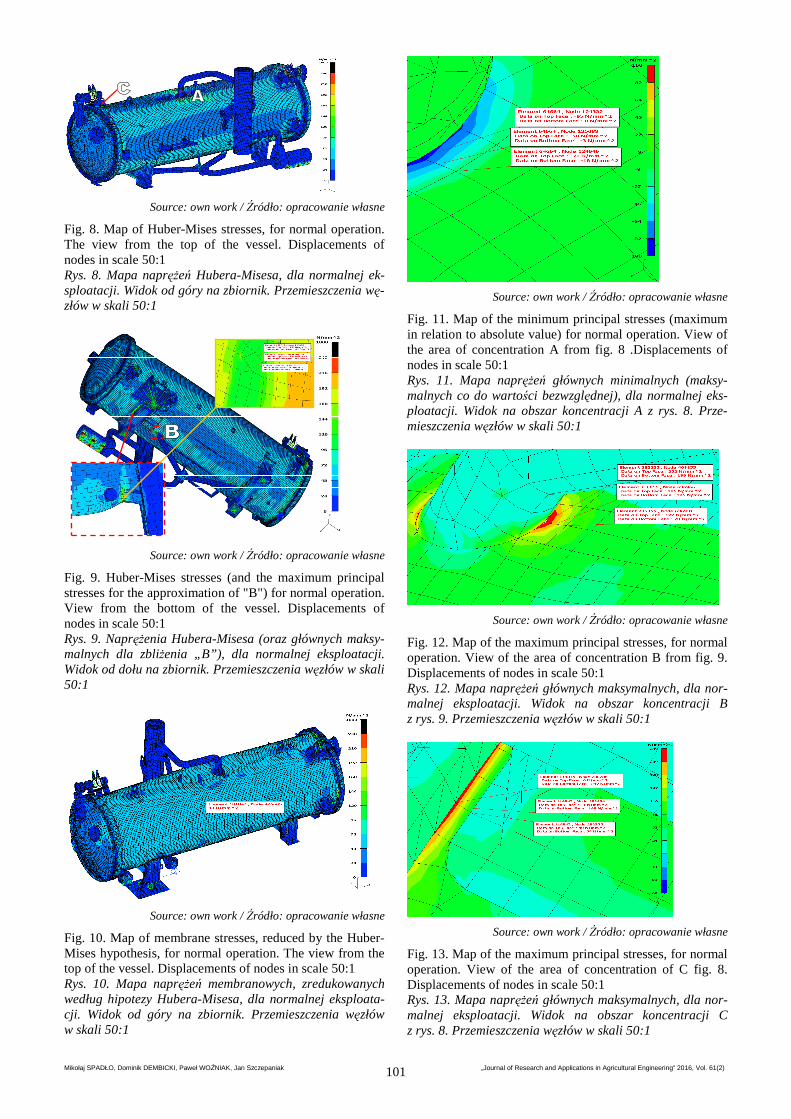
Source: own work / Źródło: opracowanie własne Fig. 7. Method of receiving degrees of freedom – green vectors represent the direction along which the possibility of movement is received. The angles of rotation remain un-fettered for each node Rys. 7. Sposób odebrania stopni swobody – zielone wektory przedstawiają kierunki, wzdłuż których odebrano możli-wość ruchu. Kąty obrotów pozostają nieskrępowane dla każdego węzła 4. The results of analyzes The results of analyzes for normal operation include figures from 8 to 13.
Mikołaj SPADŁO, Dominik DEMBICKI, Paweł WOŹNIAK, Jan Szczepaniak „Journal of Research and Applications in Agricultural Engineering” 2016, Vol. 61(2) 101
Source: own work / Źródło: opracowanie własne
Fig. 8. Map of Huber-Mises stresses, for normal operation. The view from the top of the vessel. Displacements of nodes in scale 50:1 Rys. 8. Mapa naprężeń Hubera-Misesa, dla normalnej ek-sploatacji. Widok od góry na zbiornik. Przemieszczenia wę-złów w skali 50:1
Source: own work / Źródło: opracowanie własne
Fig. 9. Huber-Mises stresses (and the maximum principal stresses for the approximation of "B") for normal operation. View from the bottom of the vessel. Displacements of nodes in scale 50:1 Rys. 9. Naprężenia Hubera-Misesa (oraz głównych maksy-malnych dla zbliżenia „B”), dla normalnej eksploatacji. Widok od dołu na zbiornik. Przemieszczenia węzłów w skali 50:1
Source: own work / Źródło: opracowanie własne
Fig. 10. Map of membrane stresses, reduced by the Huber-Mises hypothesis, for normal operation. The view from the top of the vessel. Displacements of nodes in scale 50:1 Rys. 10. Mapa naprężeń membranowych, zredukowanych według hipotezy Hubera-Misesa, dla normalnej eksploata-cji. Widok od góry na zbiornik. Przemieszczenia węzłów w skali 50:1
Source: own work / Źródło: opracowanie własne
Fig. 11. Map of the minimum principal stresses (maximum in relation to absolute value) for normal operation. View of the area of concentration A from fig. 8 .Displacements of nodes in scale 50:1 Rys. 11. Mapa naprężeń głównych minimalnych (maksy-malnych co do wartości bezwzględnej), dla normalnej eks-ploatacji. Widok na obszar koncentracji A z rys. 8. Prze-mieszczenia węzłów w skali 50:1
Source: own work / Źródło: opracowanie własne
Fig. 12. Map of the maximum principal stresses, for normal operation. View of the area of concentration B from fig. 9. Displacements of nodes in scale 50:1 Rys. 12. Mapa naprężeń głównych maksymalnych, dla nor-malnej eksploatacji. Widok na obszar koncentracji B z rys. 9. Przemieszczenia węzłów w skali 50:1
Source: own work / Źródło: opracowanie własne
Fig. 13. Map of the maximum principal stresses, for normal operation. View of the area of concentration of C fig. 8. Displacements of nodes in scale 50:1 Rys. 13. Mapa naprężeń głównych maksymalnych, dla nor-malnej eksploatacji. Widok na obszar koncentracji C z rys. 8. Przemieszczenia węzłów w skali 50:1

Mikołaj SPADŁO, Dominik DEMBICKI, Paweł WOŹNIAK, Jan Szczepaniak „Journal of Research and Applications in Agricultural Engineering” 2016, Vol. 61(2) 102
Based on drawings for the analyzes of acute states: • Primary global membrane stresses do not ex-ceed the limit of 130 MPa. These stresses reach a value about 50 MPa (fig. 10). • Primary local membrane stresses and do not exceed the limit of 195 MPa. This is shown in the draw-ings presenting concentrations. The stress limit range
= 390 MPa is not exceeded. This range is calculat-ed as the difference stresses during normal operation and dur-ing unloading, when the pressure inside it is equal to zero. With regard to the fatigue strength of construction it was located several areas of stress concentration: • In the place where the flange connects to the upper pipeline. • In the place where the tube connects to the lower steam circuit with a vessel. • In weld metal supports, with the base plate. • In strengthening sheet metal of rotation mechanism of cover with buckles According to EN 13445-3 and the data included in the area of 1. corresponds to type of connection with designa-tion 7.3b and it has a class 63, the area of 2. is 2.1a – class 63, the area of 3. is 6.3 – class 80, area of 4 is 6.1 – class 80 (fig. 14).
Area 1. Area 2. Area 3. Area 4.
Fig. 14. Types of welded joints according to PN EN 13445-3 [4] Rys. 14. Zestawienie typów połączeń spawanych według PN EN 13445-3 [4] For the area 1. 100 MPa determined by the extrapolative stresses techniques as it was described in, for area 2. - 250 MPa, for area 3. - 160 MPa, for area 4. - 250 MPa. With these levels of stresses and with the established classes of welds, it is estimated that a fatigue crack occurs when: • Area 1 – 48500 cycles; • Area 2 – 31040 cycles; • Area 3 – 241552 cycles; • Area 4 – 63321 cycles. These values are determined using the relationship:
.
The size of C and m are given in standards EN 13445-3 according to weld classes, and is a factor correction. The results of analyzes for tests are presented in figures from 15 to 18.
Source: own work / Źródło: opracowanie własne
Fig. 15. Map of Huber-Misses stresses, for pressure test. The view from the top of the vessel. Displacements of nodes in scale 50:1 Rys. 15. Mapa naprężeń Hubera-Misesa, dla próby ciśnieniowej. Widok od góry na zbiornik. Przemieszczenia węzłów w skali 50:1
Source: own work / Źródło: opracowanie własne
Fig. 16. Map of Huber-Misses stresses, for pressure test. View of the area of stress concentration A from fig. 15. Displacements of nodes in scale 50:1 Rys. 16. Mapa naprężeń Hubera-Misesa, dla próby ciśnieniowej. Widok na obszar koncentracji naprężeń A z rys. 15. Przemieszczenia węzłów w skali 50:1
Source: own work / Źródło: opracowanie własne
Fig. 17. Map of Huber-Misses stresses, for pressure test. View of the area of stress concentration B from fig. 15. Displacements of nodes in scale 50:1 Rys. 17. Mapa naprężeń Hubera-Misesa, dla próby ciśnieniowej. Widok na obszar koncentracji naprężeń B z rys. 15. Przemieszczenia węzłów w skali 50:1
Source: own work / Źródło: opracowanie własne
Fig. 18. Map of Huber-Misses stresses, for pressure test. View from the bottom of the vessel. Displacements of nodes in scale 50:1 Rys. 18. Mapa naprężeń Hubera-Misesa, dla próby ciśnieniowej. Widok od dołu na zbiornik. Przemieszczenia węzłów w skali 50:1 For the tests also found no exceedances of the limit val-ues. Especially: • The primary global membrane stress does not exceed the limit values 260 MPa. • The primary local membrane stress and
does not exceed the limit values 390 MPa. This is shown in drawings presenting concentrations. • The limit stress range = 780 MPa has not been exceeded. This range is calculated as the difference of stresses during normal operation and during unloading, when the pressure inside it is equal to zero.

Mikołaj SPADŁO, Dominik DEMBICKI, Paweł WOŹNIAK, Jan Szczepaniak „Journal of Research and Applications in Agricultural Engineering” 2016, Vol. 61(2) 103
5. Summary and conclusions Based on the stress analysis FEM of vessel it was found that the stresses do not exceed the limit values set by rec-ommendations of standard EN 13445-3 for static strength, both for pressure tests, as well as for normal operation. Therefore, it is concluded that there is a possibility to build a sterilizer and conduct further research using a prototype. However, it was noted areas of stress concentration, which can lead to the destruction of structure (unsealing of vessel) over a longer period of operation. Preliminary esti-mation of fatigue strength using recommendations of stand-ard EN 13445-3 takes place by calculating the number of cycles at which destruction occurs. For the individual case, it was found that the destruction occurs after more cycles than planned 20000. Therefore, it was found initially that object is of sufficient fatigue strength to work for 10 years. Nevertheless, at stress it is clearly indicated strain gauge measurements to confirm theoretical considerations. These measurements must be performed in accordance with re-quirements of standard EN 13445-3, ie. by method of Hot Spot using extrapolative techniques.
6. References [1] Czarniecka-Skubina E., Nowak D. (red.): Technologia żywno-
ści. Cz. 1. Podstawy technologii żywności. Warszawa, 2010.
[2] Moss R., Basic M.: Pressure Vessel Design Manual. 4th Edi-tion. Butterworth-Heinemann, 2012.
[3] Norma EN 10088-2:2005: Stale odporne na korozję - Część 2: Warunki techniczne dostawy blach i taśm ze stali nierdzew-nych ogólnego przeznaczenia.
[4] Norma PN EN 13445. Nieogrzewane płomieniem zbiorniki ciśnieniowe. Część 3: Projektowanie.
[5] Spadło M., Szczepaniak J.: Aproksymacja naprężeń zreduko-wanych z wykorzystaniem składowych tensora płaskiego sta-nu naprężenia. Journal of Research and Applications in Agri-cultural Engineering, 2011, 56(2), 136-138.
[6] Szczepaniak J.: Construction solutions in modern food steri-lizers. Mechanization in Agriculture, Bulgaria, 2015, 3, 19-23.
[7] Szczepaniak J.: Klasyfikacja cienkościennych prętowych ele-mentów skończonych w zagadnieniach stateczności konstruk-cji nośnych maszyn rolniczych. Journal of Research and Ap-plications in Agricultural Engineering, 1999, 44(2), 81-83.