Embed Size (px)
Citation preview
Operating Instructions PSQ-E
Version 2016/08/29 2016 PS Automation GmbH

2
Contents Type key ............................................................................................................................................................. 2 1. Symbols and safety ........................................................................................................................................ 3 2. Usage as per specification.............................................................................................................................. 4 3. Storage ........................................................................................................................................................... 4 4. Operating conditions ..................................................................................................................................... 4
4.1 Installation position ................................................................................................................................... 5 5. Function ......................................................................................................................................................... 5 6. Manual operation .......................................................................................................................................... 6 7. Valve mounting .............................................................................................................................................. 6 8. Setting of the mechanical stop ...................................................................................................................... 6
8.1 Setting of the Position Indicator ................................................................................................................ 7 9. Setting of the position switches / limit switches ........................................................................................... 7
9.1 Setting of the internal limit switches ........................................................................................................ 8 9.2 Setting of the additional position switches ............................................................................................... 8
10. Electric supply .............................................................................................................................................. 8
10.1 Wiring diagram ........................................................................................................................................ 9 11. Commissioning ........................................................................................................................................... 10 12. Service/ Maintenance ................................................................................................................................ 10
12.1 Cleaning ................................................................................................................................................. 10 12.2 Spare Parts ............................................................................................................................................. 10
13. Appendix .................................................................................................................................................... 10
13.1. Accessories ........................................................................................................................................... 10 13.2 Declaration of Incorporation of Part Completed Machinery and EC Declaration of Conformity in compliance with the Directives on EMC and Low Voltage .................................................... 11
Type key
example
PSQ-E100 / 400VAC / 50-60Hz / 20W / 100Nm / 23 Actuator type Voltage Supply Frequency Nom. power consumption Max. torque Actuating time [mm/s]
3
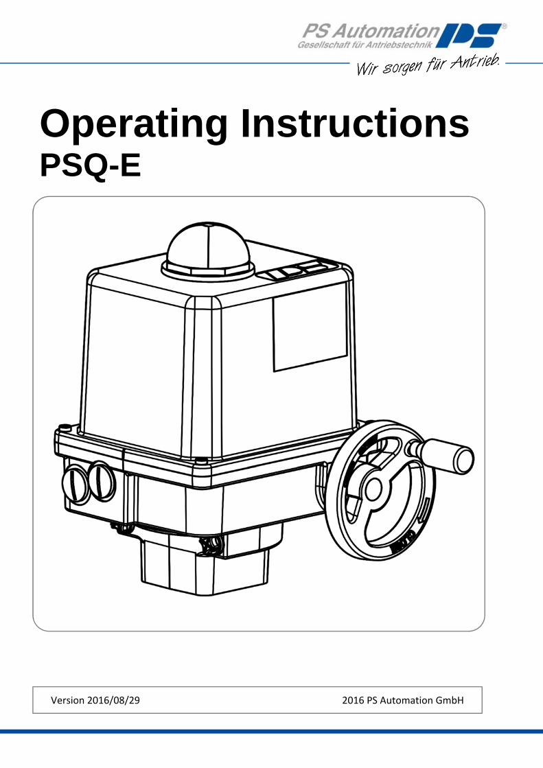
1. Symbols and safety Danger signs
The following danger signs are used in this operating manual:
Caution! There is a general risk of damage related to health and/or properties. Danger! Electrical voltages are present that may lead to death. Life threatening risks may occur due to electrical voltages! Avoid personal or material damages by observing applicable regulations and safety standards!
Other notes
The motor surface temperature may rise when maintaining, inspecting and repairing the actuator immediately after the operation. There is a danger of burning the skin!
Always consult the relevant operating instructions when mounting PS accessories or operating the actuator with PS accessories.
Connections for signal in‐ and output are double isolated from circuits that can be under dangerous voltage.
General dangers of non‐compliance with safety regulations
PSQ‐E actuators are built at state‐of the art technology and are safe to operate. Despite of this, the actuators may be hazardous if operated by personnel that has not been sufficiently trained or at least instructed, and if the actuators are handled improperly, or not used as per specification. This may
cause danger to life and limb of the user or a third party,
damage the actuator and other property belonging to the owner,
reduce safety and function of the actuator. To prevent such problems, please ensure that these operating instructions and the safety regulations in particular have been read and understood by all personnel involved in the installation, commissioning, operation, maintenance and repair of the actuators.
Basic safety notes
The actuators may only be operated by skilled and authorized operating personnel.
Make sure to follow all security advices mentioned in this manual, any national rules for accident prevention, as well as the owner´s instructions for work, operation and safety.
The isolating procedures specified in these Operating Instructions must be followed for all work pertaining to the installation, commissioning, operation, change of operating conditions and modes, maintenance, inspection, repair and installation of accessories
Before opening the actuator cover, ensure that mains supply is isolated and prevented from unintended re‐connection.
Areas that can be under voltage have to be isolated before working on them.
Ensure that the actuators are always operated in faultless condition. Any damage or faults, and changes in the operational characteristics that may affect safety, must be reported at once.
4
2. Usage as per specification PSQ‐E quarter turn actuators are exclusively designed to be used as electric valve actuators. They
are meant to be mounted on valves in order to run their motors.
Any other use is considered to be non‐compliant and the manufacturer cannot be held liable for any damage resulting from it.
The actuators can only be used within the limits laid out in the data sheets, catalogues and other documents. Otherwise, the manufacturer cannot be held liable for any resulting damage.
Usage as per specification includes the observance of the operating, service and maintenance conditions laid down by the manufacturer.
Not to be regarded as usage as per specification are mounting and adjusting the actuator as well as servicing. Special precautions have to be taken while doing this!
The actuators may only be used, serviced and repaired by personnel that is familiar with them and informed about potential hazards. The specific regulations for the prevention of accidents have to be observed.
Damages caused by unauthorized modifications carried out on the actuators are excluded from the manufacturer's liability.
Supply voltage may only be switched on after the proper closure of the main cover or terminal box.
3. Storage For appropriate storage, the following instructions have to be met:
Only store the actuators in ventilated, dry rooms.
Store the actuators on shelves, wooden boards, etc., to protect them from floor moisture.
Cover the actuators with plastic foil to protect them from dust and dirt.
Protect the actuators against mechanical damage.
4. Operating conditions The standard actuators can be operated at ambient temperatures from ‐25°C to +70°C. Ambient temperature range for modulating duty is from ‐25°C to +70°C.
The operating modes correspond to IEC 60034‐1, 8 S2 for short cycle 20 min. S3/S4 control operation 1200 c/h – 25% ED at 25°C.
For protection against moisture and dust, the actuator enclosure rating is IP67 according to EN 60529. To ensure the protection rating, the cover must be fitted correctly and the holding screws tightened crosswise. The cable glands must be suitable for the cables and correctly fitted to the actuator.
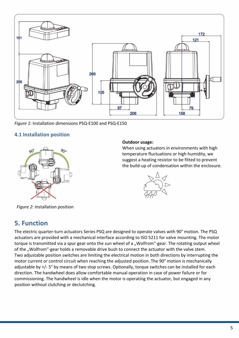
When installing the actuators, leave enough space to permit cover removal (Figure 1).
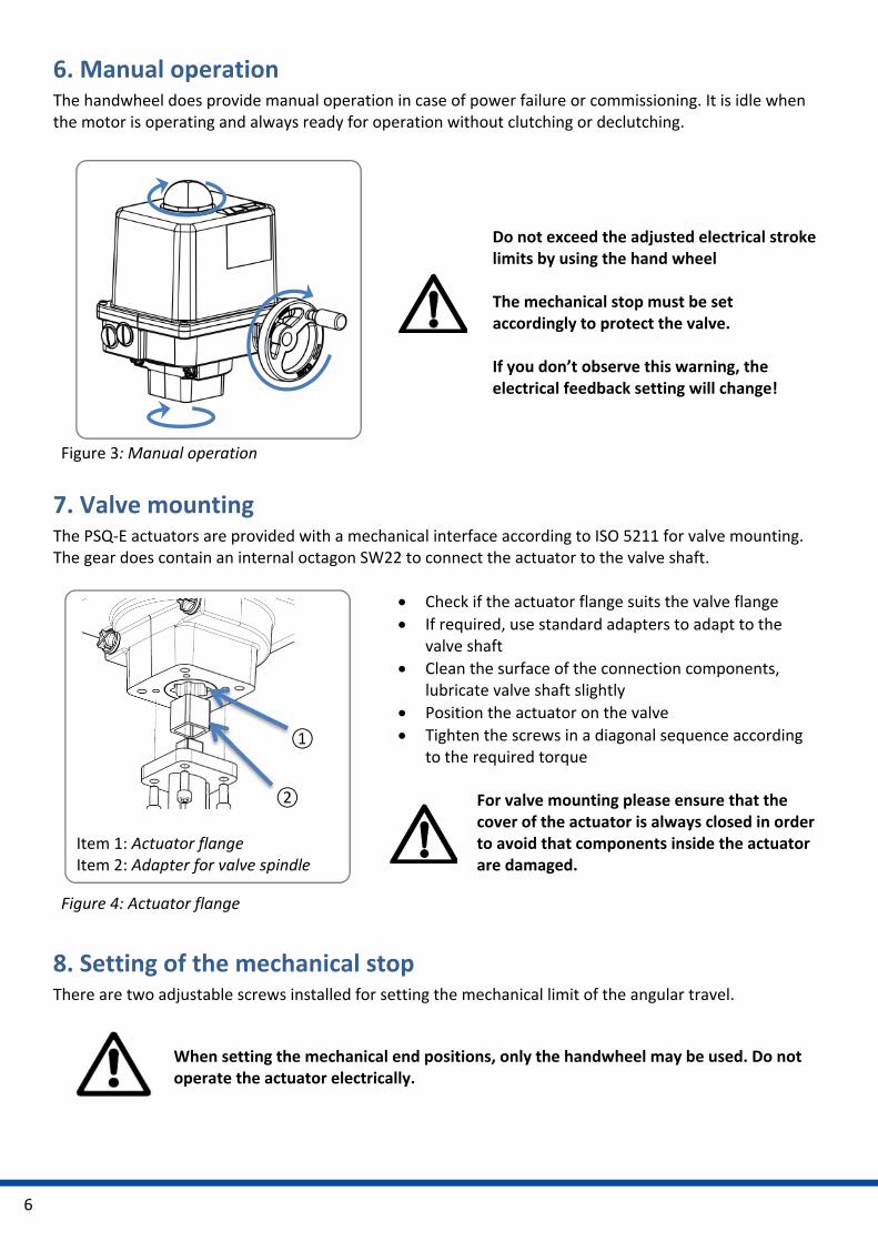
Any installation position is allowed except “cover pointing downwards” (figure 2).
5
Figure 1: Installation dimensions PSQ‐E100 and PSQ‐E150
4.1 Installation position
Figure 2: Installation position
Outdoor usage: When using actuators in environments with high temperature fluctuations or high humidity, we suggest a heating resistor to be fitted to prevent the build‐up of condensation within the enclosure.
5. Function The electric quarter‐turn actuators Series PSQ are designed to operate valves with 90° motion. The PSQ actuators are provided with a mechanical interface according to ISO 5211 for valve mounting. The motor torque is transmitted via a spur gear onto the sun wheel of a „Wolfrom“‐gear. The rotating output wheel of the „Wolfrom“‐gear holds a removable drive bush to connect the actuator with the valve stem. Two adjustable position switches are limiting the electrical motion in both directions by interrupting the motor current or control circuit when reaching the adjusted position. The 90° motion is mechanically adjustable by +/‐ 5° by means of two stop screws. Optionally, torque switches can be installed for each direction. The handwheel does allow comfortable manual operation in case of power failure or for commissioning. The handwheel is idle when the motor is operating the actuator, but engaged in any position without clutching or declutching.
6
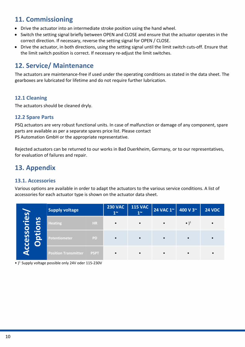
Item 1: Actuator flange Item 2: Adapter for valve spindle
6. Manual operation The handwheel does provide manual operation in case of power failure or commissioning. It is idle when the motor is operating and always ready for operation without clutching or declutching.
Figure 3: Manual operation
Do not exceed the adjusted electrical stroke limits by using the hand wheel The mechanical stop must be set accordingly to protect the valve. If you don’t observe this warning, the electrical feedback setting will change!
7. Valve mounting The PSQ‐E actuators are provided with a mechanical interface according to ISO 5211 for valve mounting. The gear does contain an internal octagon SW22 to connect the actuator to the valve shaft.
Figure 4: Actuator flange
Check if the actuator flange suits the valve flange
If required, use standard adapters to adapt to the valve shaft
Clean the surface of the connection components, lubricate valve shaft slightly
Position the actuator on the valve
Tighten the screws in a diagonal sequence according to the required torque
For valve mounting please ensure that the cover of the actuator is always closed in order to avoid that components inside the actuator are damaged.
8. Setting of the mechanical stop There are two adjustable screws installed for setting the mechanical limit of the angular travel.
When setting the mechanical end positions, only the handwheel may be used. Do not operate the actuator electrically.
①
②

7
Remove the protection cap (, item 3) from either stop screw.
Unscrew both stop screws anti‐clockwise by approximately 5 turns.
Move the actuator to the closed position by turning the handwheel clockwise.
Turn the stop screw for closed position (, item 1) to the stop.
Move the actuator to the open position by turning the handwheel anti‐clockwise.
Turn the stop screw for open position (, item 2) finger tight.
Screw on the protection cap onto the stop screw.
Figure 5: Mechanical stop
Item 1: Stop screw CLOSED position Item 2: Stop screw OPEN position Item 3: Protecting caps
8.1 Setting of the Position Indicator
The position indicator is a two‐coloured half ball turning under a transparent dome with blackened quarter segments.
Figure 6: position indicator
Take off the cover and turn the half ball as appropriate to adjust the position indicator.
9. Setting of the position switches / limit switches
Figure 7: Limit switches / position switches
The limit switches are pre‐adjusted in the factory. These standard limit switches serve to switch off the motor when the end positions are reached. Additional position switches are free of voltage and serve to indicate the valve position ① Position switch OPEN
② Position switch CLOSE
③ Limit switch OPEN
④ Limit switch CLOSE
A‐D Switching cams
① ②
③
③
A‐D ①‐④

8
9.1 Setting of the internal limit switches
Ensure that the mains supply is secured against accidental switching‐on!
The limit switches are pre‐adjusted in the factory. An additional adjustment of the two lower switching cams is normally not necessary. If you wish to adjust the limit switches yourself, please follow the these instructions:
Run the actuator by using the hand wheel in direction to the closed position until the required position is reached.
Turn the cam of the CLOSE limit switch (Figure 8, Pos. D) with a suitable screw driver (4 mm blade width) clockwise until you hear the micro switch click.
Run the actuator by using the hand wheel in direction to the open position until the required position is reached.
Turn the cam of the OPEN limit switch (Figure 8, Pos. C) with a suitable screw driver (4 mm blade width) counter‐clockwise until the micro switch is heard to click.
Check the switching position and repeat the adjustment if necessary.
Figure 8: Setting the switching cams for the position switches
A Switching cam for ① position switch OPEN/ Feedback
signal
B Switching cam for ② position switch
CLOSE/ Feedback signal
C Switching cam for ③ limit switch OPEN/ Motor
cut‐off
D Switching cam for ④ limit switch CLOSE/ Motor
cut‐off
E Supporting bridge for screwdriver
NOTE: Use the bridge (Figure 8, Pos. E) as support for the screw driver when adjusting the cams.
9.2 Setting of the additional position switches
Run the actuator by turning the hand wheel in CLOSE position until the required position is reached.
Turn the cam of the the CLOSE limit switch (Figure 8, Pos. B) with a suitable screw driver (4 mm blade width) clockwise until the micro switch is heard to click.
Run the actuator by turning the hand wheel in OPEN position until the required position is reached.
Turn the cam of the OPEN limit switch (Figure 8, Pos. A) with a suitable screw driver (4 mm blade width) counter‐clockwise until the micro switch is heard to click.
Check the switching position and repeat the adjustment if necessary.
10. Electric supply
Switch mains off before starting to work! Connect acc. to wiring diagram on the main frame.
B
D C
A
E
E

9
The mains supply cords must be suitably dimensioned to accept the maximum current requirement of the actuator, and correspond to IEC 227 and IEC 245. The yellow‐green coloured cables may only be used for connecting to earth. When inserting the cable through the cable connector, ensure that the maximum bending radius for the cable is observed. The PSQ‐E electric actuators do not have an internal electrical power switch. A power mains switch has therefore to be provided in the installation. This should be positioned close to the device and be easily accessible to the user and shall be labelled as the mains isolator switch for the actuator. Electric installation as well as over‐current and overvoltage protection devices must be conform to the standard DIN IEC 60364‐4‐41, protective class I and also to the standard DIN IEC 60364‐4‐44 according to the applied overvoltage category of the actuator.
With protective low voltage 24 VAC the open motor phase can produce voltages between 30‐35 V due to motor generated induction voltage.
10.1 Wiring diagram
Figure 9 shows the standard electrical connections. However, the wiring diagram inside the actuator hood is valid for the specific actuator. For any optional extras see the individual wiring diagram in the related service instructions. Two adjustable limit switches are installed to limit the stroke of the actuator, and cut‐off the motor current in the relative direction.
PE Earth connection on housing plate has to be connected!
Figure 9: Wiring diagram
230, 115, 24 VAC 1~ 400 VAC 3~ 24 VDC
10
11. Commissioning Drive the actuator into an intermediate stroke position using the hand wheel.
Switch the setting signal briefly between OPEN and CLOSE and ensure that the actuator operates in the correct direction. If necessary, reverse the setting signal for OPEN / CLOSE.
Drive the actuator, in both directions, using the setting signal until the limit switch cuts‐off. Ensure that the limit switch position is correct. If necessary re‐adjust the limit switches.
12. Service/ Maintenance The actuators are maintenance‐free if used under the operating conditions as stated in the data sheet. The gearboxes are lubricated for lifetime and do not require further lubrication.
12.1 Cleaning
The actuators should be cleaned dryly.
12.2 Spare Parts
PSQ actuators are very robust functional units. In case of malfunction or damage of any component, spare parts are available as per a separate spares price list. Please contact PS Automation GmbH or the appropriate representative. Rejected actuators can be returned to our works in Bad Duerkheim, Germany, or to our representatives, for evaluation of failures and repair.
13. Appendix
13.1. Accessories
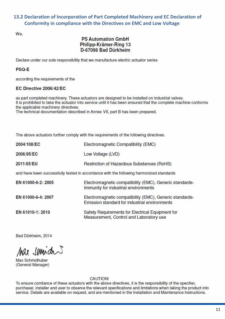
Various options are available in order to adapt the actuators to the various service conditions. A list of accessories for each actuator type is shown on the actuator data sheet.
Accessories/
Options
Supply voltage 230 VAC
1~ 115 VAC
1~ 24 VAC 1~ 400 V 3~ 24 VDC
Heating HR • • • • )1 •
Potentiometer PD • • • • •
Position Transmitter PSPT • • • • •
• )1 Supply voltage possible only 24V oder 115‐230V
11
13.2 Declaration of Incorporation of Part Completed Machinery and EC Declaration of Conformity in compliance with the Directives on EMC and Low Voltage
12
PS Automation GmbH
Gesellschaft für Antriebstechnik Philipp‐Krämer‐Ring 13 D‐67098 Bad Dürkheim Tel.: +49 (0) 63 22 ‐ 60 03 – 0 Fax: +49 (0) 63 22 ‐ 60 03 – 20 eMail: info@ps‐automation.com www.ps‐automation.com
Hong Kong MaxAuto Company Ltd. Room 2008, 20/F., CCT Telecom Building 11 Wo Shing Street Fotan, Shatin, Hong Kong Tel.: <+852> 26 87‐50 00 Fax: <+852> 81 01‐37 43 eMail: [email protected] www.maxonicauto.com China Shenzhen Maxonic Automation Control Co., Ltd. Maxonic Automation Control Mansion No. 3 Lang Shan Road, Hi‐Tech Industrial Park, Shenzhen, Guangdong, PRC. 518057 Tel.: <+86> 7 55 26 52 18 78 Fax: <+86> 7 55 26 05 28 00 eMail: [email protected] www.maxonicauto.com Indien PS Automation India Pvt Ltd. Srv. No. 25/1, Narhe Industrial Area, A.P. Narhegaon, Tal. Haveli, Dist. IND‐411041 Pune Tel. : <+ 91> 20 25 47 39 66 Fax : <+ 91> 20 25 47 39 66 eMail : sales@ps‐automation.in www.ps‐automation.in
Grossbritannien IMTEX Controls Ltd. Unit 5A, Valley Industries, Hadlow Road GB‐Tonbridge, Kent TN11 0AH Tel.: <+44> (0) 17 32‐85 03 60 Fax: <+44> (0) 17 32‐85 21 33 eMail: sales@imtex‐controls.com www.imtex‐controls.com Italien PS Automazione S.r.l. Via Pennella, 94 I‐38057 Pergine Valsugana (TN) Tel.: <+39> 04 61‐53 43 67 Fax: <+39> 04 61‐50 48 62 eMail: info@ps‐automazione.it Spanien Sertemo, S.L. Pol. Ind. Alba ‐ Avda. Generalitat 15 Apartado de Correos, 142 E‐43480 Vila‐Seca (Tarragona) Tel. : <+34> 9 77 39 11 09 Fax : <+34> 9 77 39 44 80 eMail : [email protected]
![HYI LPK ZT PSQ¥ SV ]LU 3V ]V T HYI LPK ZT PSQ¥ HYI LPK Z[PK … · 2020. 2. 6. · 3v ]v t hyi lpk zt psq¥ hyi lpk z[pk v n z[psspun z]lyut ] hyi lpk zt psq¥ sv ]lu 'dwr / 2 9](https://img.pdfslide.net/doc/110x75/60cb7cf496f36d7ab408a768/hyi-lpk-zt-psq-sv-lu-3v-v-t-hyi-lpk-zt-psq-hyi-lpk-zpk-2020-2-6-3v-v.jpg)