Embed Size (px)
Citation preview
Via Mantova, 177/A - 37053 Cerea (Verona) Italy - Tel. +39 0442 330422 r.a. - Fax +39 0442 331054 - e-mail: [email protected] - www.fadini.net
EUROPEAN MARK CERTIFYING CONFORMITYTO THE ESSENTIAL REQUIREMENTS OF THESTANDARDS 98/37/EC
• DECLARATION OF CONFORMITY• SAFETY NORMS• EN 12453, EN 12445 STANDARDS• CEI EN 60204-1 STANDARDS• WARRANTY CERTIFICATE ON THE CUSTOMER’S REQUEST
The growth of MECCANICA FADINI has always been based on the development of guaranteed products thanks to our “TOTAL QUALITYCONTROL” system which ensures constant quality standards, updated knowledge of the European Standards and compliance withtheir requirements, in view of an ever increasing process of improvement.
The “CE” mark certifies that the operator conforms to the essential requirements of the European Directive art. 10 EEC 73/23, in relationto the manufacturer’s declaration for the supplied items, in compliance with the body of the regulations ISO 9000= UNI EN 29000.Automation in conformity to EN 12453, EN 12445 safety standards.
10-2
005
IMPORTANT WARNING NOTES- Before installing the equipment carry out a Risk Analysis and fit any required device in compliance with EN 12445 and EN 12453 Safety Norms.- It is recommended to keep to the instructions here outlined. Check the specifications on the motor sticker with your mains supply.- Dispose properly of the packaging: cardboard, nylon, polystyrene, through specializing companies.- Should the operator be removed, do not cut the electric cable. This must be properly removed from the terminal board in the junction box.- Switch off the mains switch before removing the junction box cover where the electric cable is terminated.- All the system must be earthed by using the yellow/green wire, marked by its specific symbol.- It is recommended to read the regulations, suggestions and remarks quoted in the booklet “Safety Norms”.
CHECKING AND MAINTENANCE:To achieve an optimum performance and longer life of the equipment and in observance of the safety regulations, it is recommended that inspectionsand proper maintenance are made by qualified technicians to the whole installation ie, both the mechanical and electronic parts, as well as wiring:- Mechanical parts: maintenance every 6 months approx.- Eletronic apparatus and safety equipment: maintenance every month.
®
INSTALLATION MANUALGB
AUTOMATIC GATE MANUFACTURERS
®
s.n.c.
The manufacturers reserve the right to change the products without any previousnotice and are not liable for possible damages to people and properties.
Distributor’s box
Made in Italy
®
APROLI 480 OIL-HYDRAULIC OPERATOR FOR GARAGE DOORS
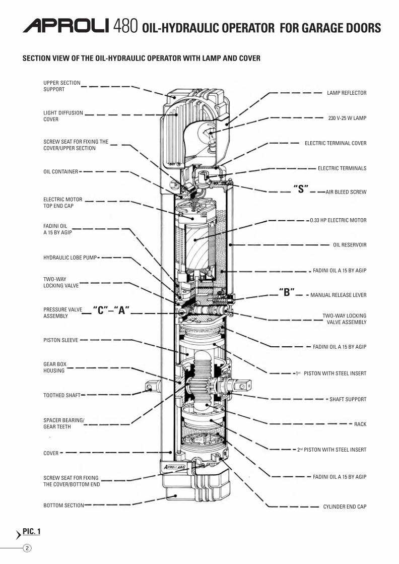
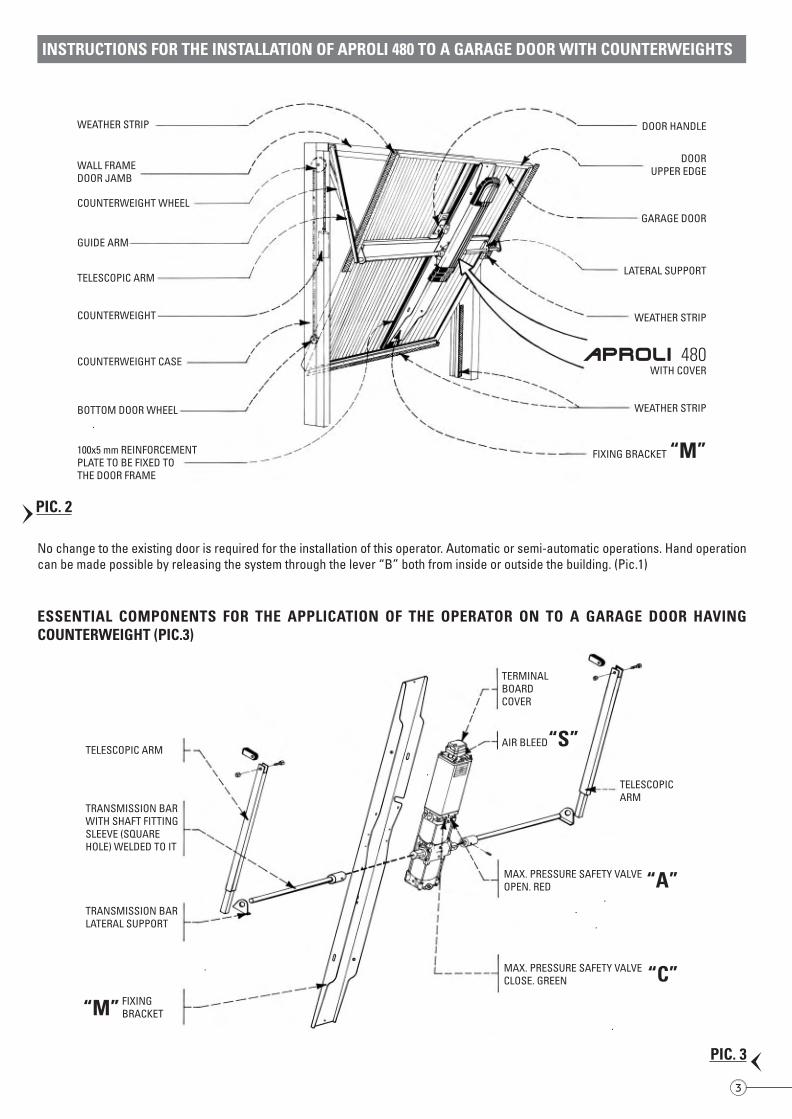
No change to the existing door is required for the installation of this operator. Automatic or semi-automatic operations. Hand operationcan be made possible by releasing the system through the lever “B” both from inside or outside the building. (Pic.1)
INSTRUCTIONS FOR THE INSTALLATION OF APROLI 480 TO A GARAGE DOOR WITH COUNTERWEIGHTS
SECTION VIEW OF THE OIL-HYDRAULIC OPERATOR WITH LAMP AND COVER
UPPER SECTIONSUPPORT
LIGHT DIFFUSIONCOVER
SCREW SEAT FOR FIXING THECOVER/UPPER SECTION
OIL CONTAINER
ELECTRIC MOTORTOP END CAP
FADINI OILA 15 BY AGIP
HYDRAULIC LOBE PUMP
TWO-WAYLOCKING VALVE
PRESSURE VALVEASSEMBLY
“C”–“A”
PISTON SLEEVE
GEAR BOXHOUSING
TOOTHED SHAFT
SPACER BEARING/GEAR TEETH
COVER
SCREW SEAT FOR FIXINGTHE COVER/BOTTOM END
BOTTOM SECTION
LAMP REFLECTOR
230 V-25 W LAMP
ELECTRIC TERMINAL COVER
ELECTRIC TERMINALS
AIR BLEED SCREW“S”
O.33 HP ELECTRIC MOTOR
OIL RESERVOIR
FADINI OIL A 15 BY AGIP
MANUAL RELEASE LEVER“B”
TWO-WAY LOCKINGVALVE ASSEMBLY
FADINI OIL A 15 BY AGIP
1st PISTON WITH STEEL INSERT
SHAFT SUPPORT
RACK
2nd PISTON WITH STEEL INSERT
FADINI OIL A 15 BY AGIP
CYLINDER END CAP
WEATHER STRIP
WALL FRAMEDOOR JAMB
COUNTERWEIGHT WHEEL
GUIDE ARM
TELESCOPIC ARM
COUNTERWEIGHT
COUNTERWEIGHT CASE
BOTTOM DOOR WHEEL
100x5 mm REINFORCEMENTPLATE TO BE FIXED TOTHE DOOR FRAME
DOOR HANDLE
DOORUPPER EDGE
GARAGE DOOR
LATERAL SUPPORT
WEATHER STRIP
WITH COVERAPROLI 480
WEATHER STRIP
FIXING BRACKET “M”
ESSENTIAL COMPONENTS FOR THE APPLICATION OF THE OPERATOR ON TO A GARAGE DOOR HAVINGCOUNTERWEIGHT (PIC.3)
TELESCOPICARM
MAX. PRESSURE SAFETY VALVEOPEN. RED
TELESCOPIC ARM
TRANSMISSION BARWITH SHAFT FITTINGSLEEVE (SQUAREHOLE) WELDED TO IT
TRANSMISSION BARLATERAL SUPPORT
FIXINGBRACKET“M”
TERMINALBOARDCOVER
AIR BLEED“S”
“A”
MAX. PRESSURE SAFETY VALVECLOSE. GREEN “C”
2
PIC. 1
PIC. 2
3
PIC. 3
APROLI 480 OIL-HYDRAULIC OPERATOR FOR GARAGE DOORS
No change to the existing door is required for the installation of this operator. Automatic or semi-automatic operations. Hand operationcan be made possible by releasing the system through the lever “B” both from inside or outside the building. (Pic.1)
INSTRUCTIONS FOR THE INSTALLATION OF APROLI 480 TO A GARAGE DOOR WITH COUNTERWEIGHTS
SECTION VIEW OF THE OIL-HYDRAULIC OPERATOR WITH LAMP AND COVER
UPPER SECTIONSUPPORT
LIGHT DIFFUSIONCOVER
SCREW SEAT FOR FIXING THECOVER/UPPER SECTION
OIL CONTAINER
ELECTRIC MOTORTOP END CAP
FADINI OILA 15 BY AGIP
HYDRAULIC LOBE PUMP
TWO-WAYLOCKING VALVE
PRESSURE VALVEASSEMBLY
“C”–“A”
PISTON SLEEVE
GEAR BOXHOUSING
TOOTHED SHAFT
SPACER BEARING/GEAR TEETH
COVER
SCREW SEAT FOR FIXINGTHE COVER/BOTTOM END
BOTTOM SECTION
LAMP REFLECTOR
230 V-25 W LAMP
ELECTRIC TERMINAL COVER
ELECTRIC TERMINALS
AIR BLEED SCREW“S”
O.33 HP ELECTRIC MOTOR
OIL RESERVOIR
FADINI OIL A 15 BY AGIP
MANUAL RELEASE LEVER“B”
TWO-WAY LOCKINGVALVE ASSEMBLY
FADINI OIL A 15 BY AGIP
1st PISTON WITH STEEL INSERT
SHAFT SUPPORT
RACK
2nd PISTON WITH STEEL INSERT
FADINI OIL A 15 BY AGIP
CYLINDER END CAP
WEATHER STRIP
WALL FRAMEDOOR JAMB
COUNTERWEIGHT WHEEL
GUIDE ARM
TELESCOPIC ARM
COUNTERWEIGHT
COUNTERWEIGHT CASE
BOTTOM DOOR WHEEL
100x5 mm REINFORCEMENTPLATE TO BE FIXED TOTHE DOOR FRAME
DOOR HANDLE
DOORUPPER EDGE
GARAGE DOOR
LATERAL SUPPORT
WEATHER STRIP
WITH COVERAPROLI 480
WEATHER STRIP
FIXING BRACKET “M”
ESSENTIAL COMPONENTS FOR THE APPLICATION OF THE OPERATOR ON TO A GARAGE DOOR HAVINGCOUNTERWEIGHT (PIC.3)
TELESCOPICARM
MAX. PRESSURE SAFETY VALVEOPEN. RED
TELESCOPIC ARM
TRANSMISSION BARWITH SHAFT FITTINGSLEEVE (SQUAREHOLE) WELDED TO IT
TRANSMISSION BARLATERAL SUPPORT
FIXINGBRACKET“M”
TERMINALBOARDCOVER
AIR BLEED“S”
“A”
MAX. PRESSURE SAFETY VALVECLOSE. GREEN “C”
2
PIC. 1
PIC. 2
3
PIC. 3
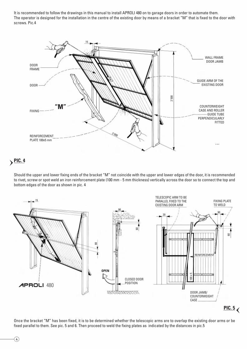
It is recommended to follow the drawings in this manual to install APROLI 480 on to garage doors in order to automate them.The operator is designed for the installation in the centre of the existing door by means of a bracket “M” that is fixed to the door withscrews. Pic.4
DOORFRAME
DOOR
FIXING“M”
REINFORCEMENTPLATE 100x5 mm
WALL FRAMEDOOR JAMB
GUIDE ARM OF THEEXISTING DOOR
COUNTERWEIGHTCASE AND ROLLER
GUIDE TUBEPERPENDICULARLY
FITTED
3˙000
2˙50
0Should the upper and lower fixing ends of the bracket “M” not coincide with the upper and lower edges of the door, it is recommendedto rivet, screw or spot weld an iron reinforcement plate (100 mm - 5 mm thickness) vertically across the door so to connect the top andbottom edges of the door as shown in pic. 4
Once the bracket “M” has been fixed, it is to be determined whether the telescopic arms are to overlap the existing door arms or befixed parallel to them. See pic. 5 and 6. Then proceed to weld the fixing plates as indicated by the distances in pic.5
15
80
90
60
OPEN
CLOSED DOORPOSITION
DOOR JAMB/COUNTERWEIGHTCASE
TELESCOPIC ARM TO BEPARALLEL FIXED TO THEEXISTING DOOR ARM
FIXING PLATETO WELD
REINFORCEMENT
9020
60
100
x 5
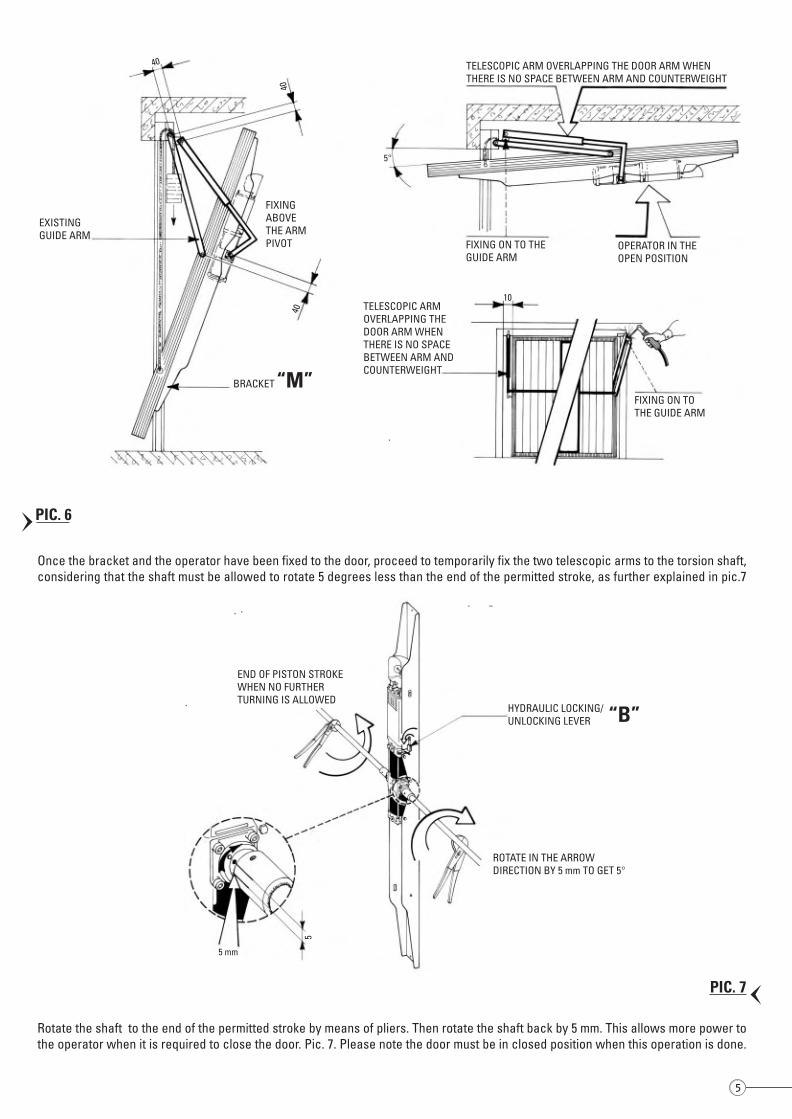
Once the bracket and the operator have been fixed to the door, proceed to temporarily fix the two telescopic arms to the torsion shaft,considering that the shaft must be allowed to rotate 5 degrees less than the end of the permitted stroke, as further explained in pic.7
BRACKET “M”
EXISTINGGUIDE ARM
40
4040
TELESCOPIC ARM OVERLAPPING THE DOOR ARM WHENTHERE IS NO SPACE BETWEEN ARM AND COUNTERWEIGHT
FIXINGABOVETHE ARMPIVOT FIXING ON TO THE
GUIDE ARMOPERATOR IN THEOPEN POSITION
TELESCOPIC ARMOVERLAPPING THEDOOR ARM WHENTHERE IS NO SPACEBETWEEN ARM ANDCOUNTERWEIGHT
10
5°
FIXING ON TOTHE GUIDE ARM
Rotate the shaft to the end of the permitted stroke by means of pliers. Then rotate the shaft back by 5 mm. This allows more power tothe operator when it is required to close the door. Pic. 7. Please note the door must be in closed position when this operation is done.
END OF PISTON STROKEWHEN NO FURTHERTURNING IS ALLOWED
HYDRAULIC LOCKING/UNLOCKING LEVER “B”
5 mm
5
ROTATE IN THE ARROWDIRECTION BY 5 mm TO GET 5°
15
APROLI 480
4
PIC. 4
PIC. 7PIC. 5
PIC. 6
5
It is recommended to follow the drawings in this manual to install APROLI 480 on to garage doors in order to automate them.The operator is designed for the installation in the centre of the existing door by means of a bracket “M” that is fixed to the door withscrews. Pic.4
DOORFRAME
DOOR
FIXING“M”
REINFORCEMENTPLATE 100x5 mm
WALL FRAMEDOOR JAMB
GUIDE ARM OF THEEXISTING DOOR
COUNTERWEIGHTCASE AND ROLLER
GUIDE TUBEPERPENDICULARLY
FITTED
3˙000
2˙50
0
Should the upper and lower fixing ends of the bracket “M” not coincide with the upper and lower edges of the door, it is recommendedto rivet, screw or spot weld an iron reinforcement plate (100 mm - 5 mm thickness) vertically across the door so to connect the top andbottom edges of the door as shown in pic. 4
Once the bracket “M” has been fixed, it is to be determined whether the telescopic arms are to overlap the existing door arms or befixed parallel to them. See pic. 5 and 6. Then proceed to weld the fixing plates as indicated by the distances in pic.5
15
80
90
60
OPEN
CLOSED DOORPOSITION
DOOR JAMB/COUNTERWEIGHTCASE
TELESCOPIC ARM TO BEPARALLEL FIXED TO THEEXISTING DOOR ARM
FIXING PLATETO WELD
REINFORCEMENT
9020
60
100
x 5
Once the bracket and the operator have been fixed to the door, proceed to temporarily fix the two telescopic arms to the torsion shaft,considering that the shaft must be allowed to rotate 5 degrees less than the end of the permitted stroke, as further explained in pic.7
BRACKET “M”
EXISTINGGUIDE ARM
40
4040
TELESCOPIC ARM OVERLAPPING THE DOOR ARM WHENTHERE IS NO SPACE BETWEEN ARM AND COUNTERWEIGHT
FIXINGABOVETHE ARMPIVOT FIXING ON TO THE
GUIDE ARMOPERATOR IN THEOPEN POSITION
TELESCOPIC ARMOVERLAPPING THEDOOR ARM WHENTHERE IS NO SPACEBETWEEN ARM ANDCOUNTERWEIGHT
10
5°
FIXING ON TOTHE GUIDE ARM
Rotate the shaft to the end of the permitted stroke by means of pliers. Then rotate the shaft back by 5 mm. This allows more power tothe operator when it is required to close the door. Pic. 7. Please note the door must be in closed position when this operation is done.
END OF PISTON STROKEWHEN NO FURTHERTURNING IS ALLOWED
HYDRAULIC LOCKING/UNLOCKING LEVER “B”
5 mm
5
ROTATE IN THE ARROWDIRECTION BY 5 mm TO GET 5°
15
APROLI 480
4
PIC. 4
PIC. 7PIC. 5
PIC. 6
5
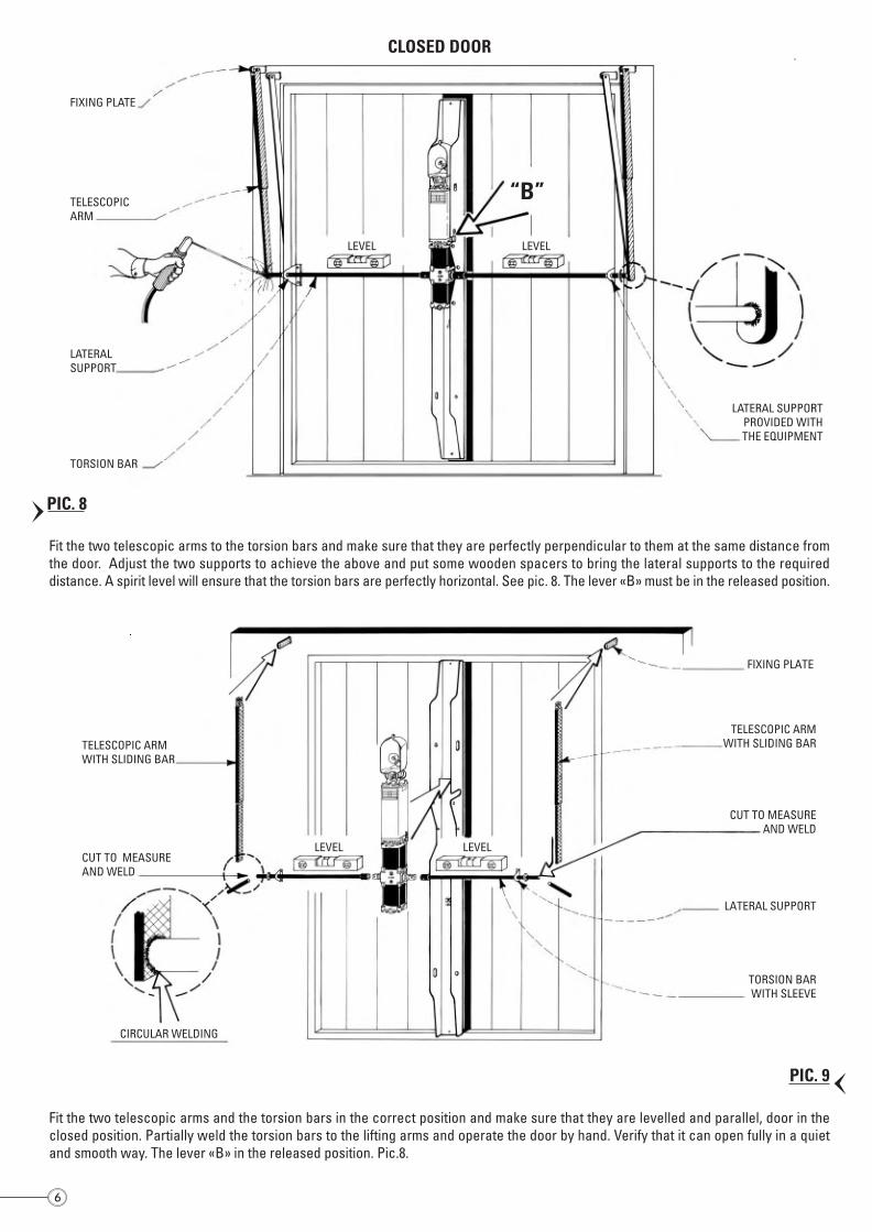
Fit the two telescopic arms to the torsion bars and make sure that they are perfectly perpendicular to them at the same distance fromthe door. Adjust the two supports to achieve the above and put some wooden spacers to bring the lateral supports to the requireddistance. A spirit level will ensure that the torsion bars are perfectly horizontal. See pic. 8. The lever «B» must be in the released position.
FIXING PLATE
TELESCOPICARM
LATERALSUPPORT
TORSION BAR
LEVEL LEVEL
“B”
LATERAL SUPPORTPROVIDED WITHTHE EQUIPMENT
CLOSED DOOR
Fit the two telescopic arms and the torsion bars in the correct position and make sure that they are levelled and parallel, door in theclosed position. Partially weld the torsion bars to the lifting arms and operate the door by hand. Verify that it can open fully in a quietand smooth way. The lever «B» in the released position. Pic.8.
TELESCOPIC ARMWITH SLIDING BAR
CUT TO MEASUREAND WELD
LEVEL LEVEL
CIRCULAR WELDING
FIXING PLATE
TELESCOPIC ARMWITH SLIDING BAR
CUT TO MEASUREAND WELD
LATERAL SUPPORT
TORSION BARWITH SLEEVE
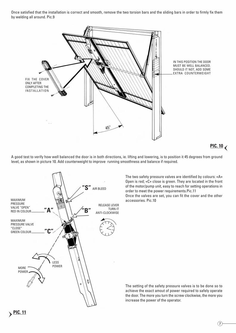
Once satisfied that the installation is correct and smooth, remove the two torsion bars and the sliding bars in order to firmly fix themby welding all around. Pic.9
FIX THE COVERONLY AFTERCOMPLETING THEI N S T A L L A T I O N
IN THIS POSITION THE DOORMUST BE WELL BALANCED.SHOULD IT NOT, ADD SOMEEXTRA COUNTERWEIGHT
45°
MAXIMUMPRESSUREVALVE “OPEN”RED IN COLOUR “A”
“C”
A good test to verify how well balanced the door is in both directions, ie. lifting and lowering, is to position it 45 degrees from groundlevel, as shown in picture 10. Add counterweight to improve running smoothness and balance if required.
MAXIMUMPRESSURE VALVE“CLOSE”GREEN COLOUR
LESSPOWERMORE
POWER
“S”
“B”RELEASE LEVER
TURN ITANTI-CLOCKWISE
AIR BLEED
The two safety pressure valves are identified by colours: «A»Open is red; «C» close is green. They are located in the frontof the motor/pump unit, easy to reach for setting operations inorder to meet the power requirements.Pic.11Once the valves are set, you can fit the cover and the otheraccessories. Pic.10
The setting of the safety pressure valves is to be done so toachieve the exact amout of power required to safely operatethe door. The more you turn the screw clockwise, the more youincrease the power of the operator.
76
PIC. 8
PIC. 9
PIC. 10
PIC. 11
Fit the two telescopic arms to the torsion bars and make sure that they are perfectly perpendicular to them at the same distance fromthe door. Adjust the two supports to achieve the above and put some wooden spacers to bring the lateral supports to the requireddistance. A spirit level will ensure that the torsion bars are perfectly horizontal. See pic. 8. The lever «B» must be in the released position.
FIXING PLATE
TELESCOPICARM
LATERALSUPPORT
TORSION BAR
LEVEL LEVEL
“B”
LATERAL SUPPORTPROVIDED WITHTHE EQUIPMENT
CLOSED DOOR
Fit the two telescopic arms and the torsion bars in the correct position and make sure that they are levelled and parallel, door in theclosed position. Partially weld the torsion bars to the lifting arms and operate the door by hand. Verify that it can open fully in a quietand smooth way. The lever «B» in the released position. Pic.8.
TELESCOPIC ARMWITH SLIDING BAR
CUT TO MEASUREAND WELD
LEVEL LEVEL
CIRCULAR WELDING
FIXING PLATE
TELESCOPIC ARMWITH SLIDING BAR
CUT TO MEASUREAND WELD
LATERAL SUPPORT
TORSION BARWITH SLEEVE
Once satisfied that the installation is correct and smooth, remove the two torsion bars and the sliding bars in order to firmly fix themby welding all around. Pic.9
FIX THE COVERONLY AFTERCOMPLETING THEI N S T A L L A T I O N
IN THIS POSITION THE DOORMUST BE WELL BALANCED.SHOULD IT NOT, ADD SOMEEXTRA COUNTERWEIGHT
45°
MAXIMUMPRESSUREVALVE “OPEN”RED IN COLOUR “A”
“C”
A good test to verify how well balanced the door is in both directions, ie. lifting and lowering, is to position it 45 degrees from groundlevel, as shown in picture 10. Add counterweight to improve running smoothness and balance if required.
MAXIMUMPRESSURE VALVE“CLOSE”GREEN COLOUR
LESSPOWERMORE
POWER
“S”
“B”RELEASE LEVER
TURN ITANTI-CLOCKWISE
AIR BLEED
The two safety pressure valves are identified by colours: «A»Open is red; «C» close is green. They are located in the frontof the motor/pump unit, easy to reach for setting operations inorder to meet the power requirements.Pic.11Once the valves are set, you can fit the cover and the otheraccessories. Pic.10
The setting of the safety pressure valves is to be done so toachieve the exact amout of power required to safely operatethe door. The more you turn the screw clockwise, the more youincrease the power of the operator.
76
PIC. 8
PIC. 9
PIC. 10
PIC. 11
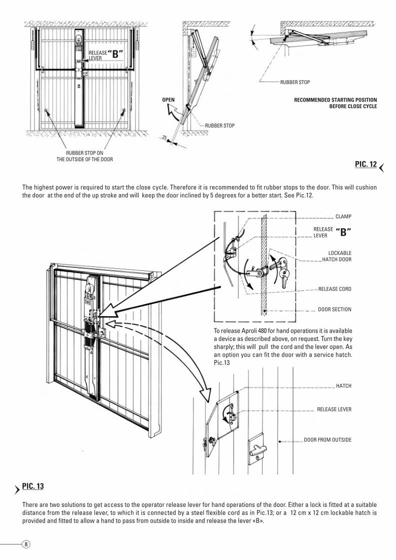
RUBBER STOP
RELEASELEVER “B”
25
OPEN
RUBBER STOP
RECOMMENDED STARTING POSITIONBEFORE CLOSE CYCLE
RUBBER STOP ONTHE OUTSIDE OF THE DOOR
The highest power is required to start the close cycle. Therefore it is recommended to fit rubber stops to the door. This will cushionthe door at the end of the up stroke and will keep the door inclined by 5 degrees for a better start. See Pic.12.
CLAMP
RELEASELEVER “B”
LOCKABLEHATCH DOOR
RELEASE CORD
DOOR SECTION
To release Aproli 480 for hand operations it is availablea device as described above, on request. Turn the keysharply; this will pull the cord and the lever open. Asan option you can fit the door with a service hatch.Pic.13
HATCH
RELEASE LEVER
DOOR FROM OUTSIDE
There are two solutions to get access to the operator release lever for hand operations of the door. Either a lock is fitted at a suitabledistance from the release lever, to which it is connected by a steel flexible cord as in Pic.13; or a 12 cm x 12 cm lockable hatch isprovided and fitted to allow a hand to pass from outside to inside and release the lever «B».
POSITION OF THEEARTH SCREWCONNECTION
CLOSE
OPEN
ELPRO 6 exp
WITH COVERAPROLI 480
ELECTRIC CABLE TO DANGLEFREE LENGTH 1.30 METRES
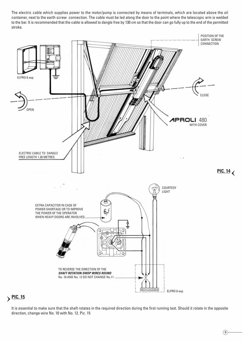
The electric cable which supplies power to the motor/pump is connected by means of terminals, which are located above the oilcontainer, next to the earth screw connection. The cable must be led along the door to the point where the telescopic arm is weldedto the bar. It is recommended that the cable is allowed to dangle free by 130 cm so that the door can go fully up to the end of the permittedstroke.
It is essential to make sure that the shaft rotates in the required direction during the first running test. Should it rotate in the oppositedirection, change wire No. 10 with No. 12. Pic. 15
COURTESYLIGHT
EXTRA CAPACITOR IN CASE OFPOWER SHORTAGE OR TO IMPROVETHE POWER OF THE OPERATORWHEN HEAVY DOORS ARE INVOLVED
TO REVERSE THE DIRECTION OF THESHAFT ROTATION SWOP WIRES ROUNDNo. 10 AND No. 12 DO NOT CHANGE No.11
10 11 12 13 14 ELPRO 6 exp
98
PIC. 14
PIC. 15
PIC. 12
PIC. 13
RUBBER STOP
RELEASELEVER “B”
25
OPEN
RUBBER STOP
RECOMMENDED STARTING POSITIONBEFORE CLOSE CYCLE
RUBBER STOP ONTHE OUTSIDE OF THE DOOR
The highest power is required to start the close cycle. Therefore it is recommended to fit rubber stops to the door. This will cushionthe door at the end of the up stroke and will keep the door inclined by 5 degrees for a better start. See Pic.12.
CLAMP
RELEASELEVER “B”
LOCKABLEHATCH DOOR
RELEASE CORD
DOOR SECTION
To release Aproli 480 for hand operations it is availablea device as described above, on request. Turn the keysharply; this will pull the cord and the lever open. Asan option you can fit the door with a service hatch.Pic.13
HATCH
RELEASE LEVER
DOOR FROM OUTSIDE
There are two solutions to get access to the operator release lever for hand operations of the door. Either a lock is fitted at a suitabledistance from the release lever, to which it is connected by a steel flexible cord as in Pic.13; or a 12 cm x 12 cm lockable hatch isprovided and fitted to allow a hand to pass from outside to inside and release the lever «B».
POSITION OF THEEARTH SCREWCONNECTION
CLOSE
OPEN
ELPRO 6 exp
WITH COVERAPROLI 480
ELECTRIC CABLE TO DANGLEFREE LENGTH 1.30 METRES
The electric cable which supplies power to the motor/pump is connected by means of terminals, which are located above the oilcontainer, next to the earth screw connection. The cable must be led along the door to the point where the telescopic arm is weldedto the bar. It is recommended that the cable is allowed to dangle free by 130 cm so that the door can go fully up to the end of the permittedstroke.
It is essential to make sure that the shaft rotates in the required direction during the first running test. Should it rotate in the oppositedirection, change wire No. 10 with No. 12. Pic. 15
COURTESYLIGHT
EXTRA CAPACITOR IN CASE OFPOWER SHORTAGE OR TO IMPROVETHE POWER OF THE OPERATORWHEN HEAVY DOORS ARE INVOLVED
TO REVERSE THE DIRECTION OF THESHAFT ROTATION SWOP WIRES ROUNDNo. 10 AND No. 12 DO NOT CHANGE No.11
10 11 12 13 14 ELPRO 6 exp
98
PIC. 14
PIC. 15
PIC. 12
PIC. 13
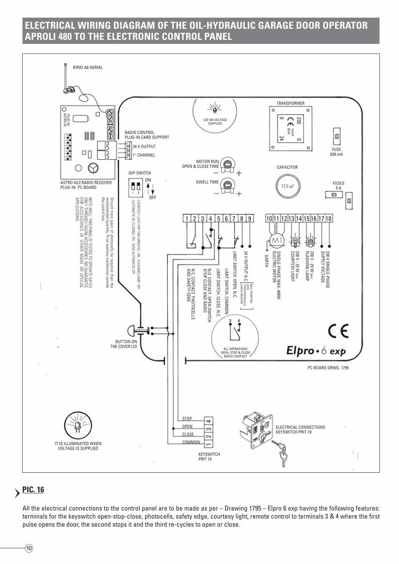
All the electrical connections to the control panel are to be made as per – Drawing 1795 – Elpro 6 exp having the following features:terminals for the keyswitch open-stop-close, photocells, safety edge, courtesy light, remote control to terminals 3 & 4 where the firstpulse opens the door, the second stops it and the third re-cycles to open or close.
ELECTRICAL WIRING DIAGRAM OF THE OIL-HYDRAULIC GARAGE DOOR OPERATORAPROLI 480 TO THE ELECTRONIC CONTROL PANEL
6 expALL OPERATIONSOPEN, STOP & CLOSE
RADIO CONTACT
3 4
BIRIO A8 AERIAL
LED ON VOLTAGESUPPLIED
TRANSFORMER230
0
024
meth
8VARADIO CONTROLPLUG-IN CARD SUPPORT
24 V OUTPUT
1° CHANNEL
ASTRO 43/2 RADIO RECEIVERPLUG-IN PC BOARD
MOTOR RUNOPEN & CLOSE TIME
DWELL TIME
1 2
ON
OFFShould more pairs of photocells be required than the
recomm
ended quantity, fit an auxiliary transformer outside
the control box.
NOTE W
ELL: THIS PANEL IS TESTED TO OPERATE GATES
ONLY THROUGH FADIN
I ACCESSORIES. NO GUARAN
TEEFO
R ACCESSO
RIES OF O
THER M
AKE O
R SPECIAL
APPLICATIONS.
- COURTESY LIGHT FOR TWO M
INUTES. ON
- FLASHING LAM
P. OFF- AUTOM
ATIC RE-CLOSING. ON
- SEMI-AUTOM
ATIC.OFF
DIP-SWITCHCAPACITOR
12,5 µF
FUSE630 mA
FUSES5 A
230 V SINGLE-PHASE
SUPPLY VOLTAGE
230 V - 25 W M
AX.
COURTESY LIGHT
SINGLE-PHASE M
AX. 400WELECTRIC M
OTOR
EARTH
MAX. PERM
ITTEDLOAD:1 PAIR PHOTOCELLS1 RADIO RECEIVER
24 V OUTPUT A.C.
LIMIT SW
ITCH. OPEN. N
.C.
LIMIT SW
ITCH. COMM
ON
LIMIT SW
ITCH. CLOSE. N.C.
N.O. CON
TACT. OPEN SW
ITCHSTOP CLOSE AN
D RADIO
N.C. CON
TACT. PHOTOCELLSAN
D SAFETY EDGE
BUTTON ONTHE COVER LID
IT IS ILLUMINATED WHENVOLTAGE IS SUPPLIED
KEYSWITCHPRIT 19
STOP
OPEN
CLOSE
COMMON
ELECTRICAL CONNECTIONSKEYSWITCH PRIT 19
PC BOARD DRWG. 1795
230 VOLTSMAINS SUPPLY
1
2
3
4
5
6
7
8
9
10
11
12
13
14
GARAGE DOOR OPERATOR COMPLETE WITH ALL THE RECOMMENDED ACCESSORIESFOR A GOOD PERFORMANCE
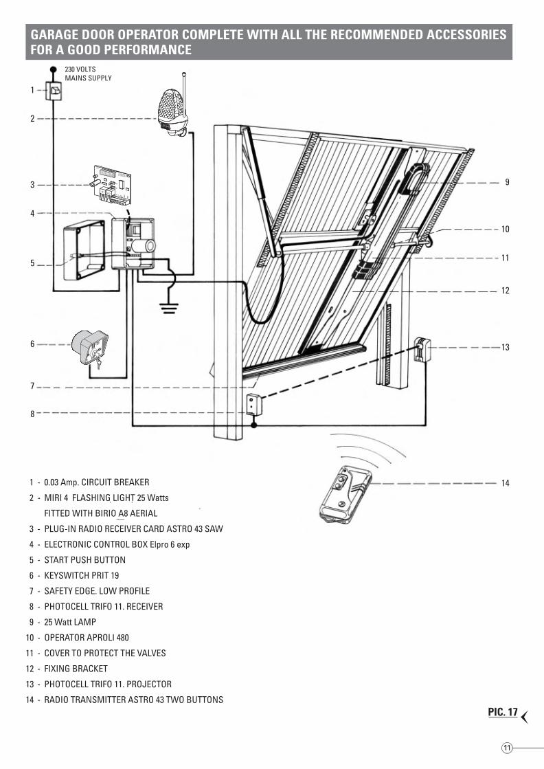
1 - 0.03 Amp. CIRCUIT BREAKER
2 - MIRI 4 FLASHING LIGHT 25 Watts
FITTED WITH BIRIO A8 AERIAL
3 - PLUG-IN RADIO RECEIVER CARD ASTRO 43 SAW
4 - ELECTRONIC CONTROL BOX Elpro 6 exp
5 - START PUSH BUTTON
6 - KEYSWITCH PRIT 19
7 - SAFETY EDGE. LOW PROFILE
8 - PHOTOCELL TRIFO 11. RECEIVER
9 - 25 Watt LAMP
10 - OPERATOR APROLI 480
11 - COVER TO PROTECT THE VALVES
12 - FIXING BRACKET
13 - PHOTOCELL TRIFO 11. PROJECTOR
14 - RADIO TRANSMITTER ASTRO 43 TWO BUTTONS
PLUG-INASTRO 43
1 2 3 4 5 6 7 8 9 10 11 12 13 14 15 16 17 18
M1
COMUN
E
230 V - 25 W M
AX.
FLASHING LAM
P
R1 R2
1234567
891
0
N.C.C N.A. GND ANT .
I.T.F.
ASTRO 43 INNESTO
R2
R1
open
12
34
PIC. 17
PIC. 16
10 11
open
All the electrical connections to the control panel are to be made as per – Drawing 1795 – Elpro 6 exp having the following features:terminals for the keyswitch open-stop-close, photocells, safety edge, courtesy light, remote control to terminals 3 & 4 where the firstpulse opens the door, the second stops it and the third re-cycles to open or close.
ELECTRICAL WIRING DIAGRAM OF THE OIL-HYDRAULIC GARAGE DOOR OPERATORAPROLI 480 TO THE ELECTRONIC CONTROL PANEL
6 expALL OPERATIONSOPEN, STOP & CLOSE
RADIO CONTACT
3 4
BIRIO A8 AERIAL
LED ON VOLTAGESUPPLIED
TRANSFORMER
2300
024
meth
8VARADIO CONTROLPLUG-IN CARD SUPPORT
24 V OUTPUT
1° CHANNEL
ASTRO 43/2 RADIO RECEIVERPLUG-IN PC BOARD
MOTOR RUNOPEN & CLOSE TIME
DWELL TIME
1 2
ON
OFFShould more pairs of photocells be required than the
recomm
ended quantity, fit an auxiliary transformer outside
the control box.
NOTE W
ELL: THIS PANEL IS TESTED TO OPERATE GATES
ONLY THROUGH FADIN
I ACCESSORIES. NO GUARAN
TEEFO
R ACCESSO
RIES OF O
THER M
AKE O
R SPECIAL
APPLICATIONS.
- COURTESY LIGHT FOR TWO M
INUTES. ON
- FLASHING LAM
P. OFF- AUTOM
ATIC RE-CLOSING. ON
- SEMI-AUTOM
ATIC.OFF
DIP-SWITCHCAPACITOR
12,5 µF
FUSE630 mA
FUSES5 A
230 V SINGLE-PHASE
SUPPLY VOLTAGE
230 V - 25 W M
AX.
COURTESY LIGHT
SINGLE-PHASE M
AX. 400WELECTRIC M
OTOR
EARTH
MAX. PERM
ITTEDLOAD:1 PAIR PHOTOCELLS1 RADIO RECEIVER
24 V OUTPUT A.C.
LIMIT SW
ITCH. OPEN. N
.C.
LIMIT SW
ITCH. COMM
ON
LIMIT SW
ITCH. CLOSE. N.C.
N.O. CON
TACT. OPEN SW
ITCHSTOP CLOSE AN
D RADIO
N.C. CON
TACT. PHOTOCELLSAN
D SAFETY EDGE
BUTTON ONTHE COVER LID
IT IS ILLUMINATED WHENVOLTAGE IS SUPPLIED
KEYSWITCHPRIT 19
STOP
OPEN
CLOSE
COMMON
ELECTRICAL CONNECTIONSKEYSWITCH PRIT 19
PC BOARD DRWG. 1795
230 VOLTSMAINS SUPPLY
1
2
3
4
5
6
7
8
9
10
11
12
13
14
GARAGE DOOR OPERATOR COMPLETE WITH ALL THE RECOMMENDED ACCESSORIESFOR A GOOD PERFORMANCE
1 - 0.03 Amp. CIRCUIT BREAKER
2 - MIRI 4 FLASHING LIGHT 25 Watts
FITTED WITH BIRIO A8 AERIAL
3 - PLUG-IN RADIO RECEIVER CARD ASTRO 43 SAW
4 - ELECTRONIC CONTROL BOX Elpro 6 exp
5 - START PUSH BUTTON
6 - KEYSWITCH PRIT 19
7 - SAFETY EDGE. LOW PROFILE
8 - PHOTOCELL TRIFO 11. RECEIVER
9 - 25 Watt LAMP
10 - OPERATOR APROLI 480
11 - COVER TO PROTECT THE VALVES
12 - FIXING BRACKET
13 - PHOTOCELL TRIFO 11. PROJECTOR
14 - RADIO TRANSMITTER ASTRO 43 TWO BUTTONS
PLUG-INASTRO 43
1 2 3 4 5 6 7 8 9 10 11 12 13 14 15 16 17 18
M1
COMUN
E
230 V - 25 W M
AX.
FLASHING LAM
P
R1 R2
1234567
891
0
N.C.C N.A. GND ANT .
I.T.F.
ASTRO 43 INNESTO
R2
R1
open
12
34
PIC. 17
PIC. 16
10 11
open
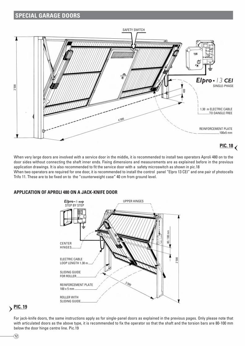
For jack-knife doors, the same instructions apply as for single-panel doors as explained in the previous pages. Only please note thatwith articulated doors as the above type, it is recommended to fix the operator so that the shaft and the torsion bars are 80-100 mmbelow the door hinge centre line. Pic.19
SPECIAL GARAGE DOORS2˙
500
4˙000
400
SAFETY SWITCH
1.30 m ELECTRIC CABLETO DANGLE FREE
REINFORCEMENT PLATE100x5 mm
13 CEISINGLE-PHASE
When very large doors are involved with a service door in the middle, it is recommended to install two operators Aproli 480 on to thedoor sides without connecting the shaft inner ends. Fixing dimensions and measurements are as explained before in the previousapplication drawings. It is also recommended to fit the service door with a safety microswitch as shown in pic.18When two operators are required for one door, it is recommended to install the control panel “Elpro 13 CEI” and one pair of photocellsTrifo 11. These are to be fixed on to the “counterweight case” 40 cm from ground level.
APPLICATION OF APROLI 480 ON A JACK-KNIFE DOOR
6 expSTEP BY STEP
CENTERHINGES
ROLLER WITHSLIDING GUIDE
UPPER HINGES
ELECTRIC CABLELOOP LENGTH 1.30 m
SLIDING GUIDEFOR ROLLER
REINFORCEMENT PLATE100 x 5 mm
2˙50
0
80 /
100
mm
3˙000
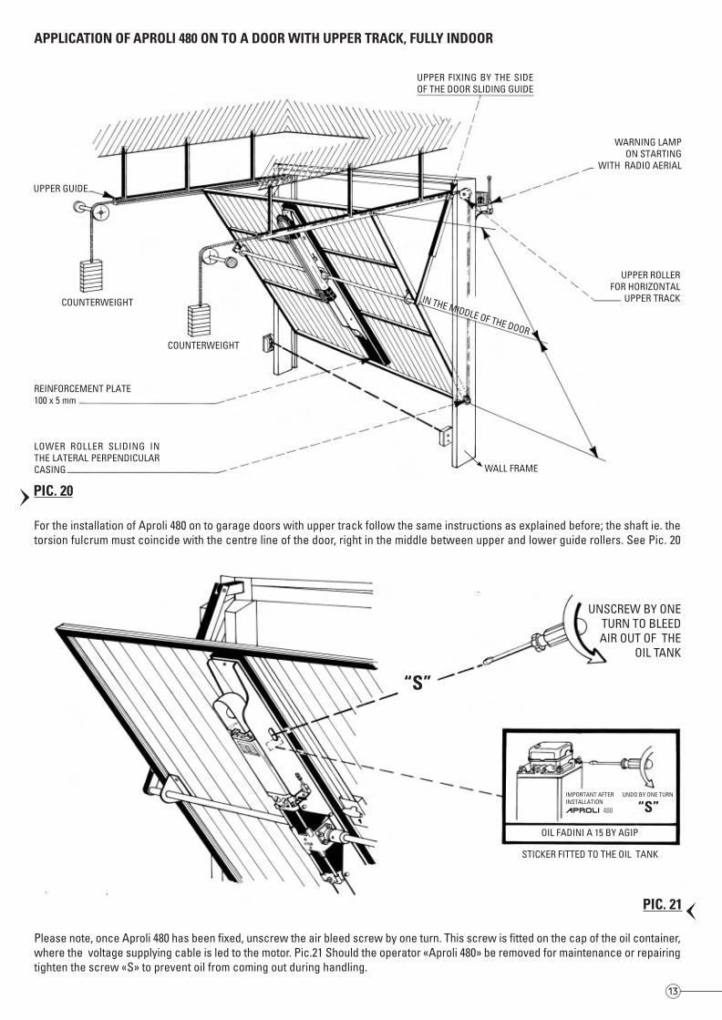
APPLICATION OF APROLI 480 ON TO A DOOR WITH UPPER TRACK, FULLY INDOOR
UPPER FIXING BY THE SIDEOF THE DOOR SLIDING GUIDE
UPPER GUIDE
REINFORCEMENT PLATE100 x 5 mm
LOWER ROLLER SLIDING INTHE LATERAL PERPENDICULARCASING
WARNING LAMPON STARTING
WITH RADIO AERIAL
UPPER ROLLERFOR HORIZONTAL
UPPER TRACK
WALL FRAME
COUNTERWEIGHT
COUNTERWEIGHT
IN THE MIDDLE OF THE DOOR
For the installation of Aproli 480 on to garage doors with upper track follow the same instructions as explained before; the shaft ie. thetorsion fulcrum must coincide with the centre line of the door, right in the middle between upper and lower guide rollers. See Pic. 20
Please note, once Aproli 480 has been fixed, unscrew the air bleed screw by one turn. This screw is fitted on the cap of the oil container,where the voltage supplying cable is led to the motor. Pic.21 Should the operator «Aproli 480» be removed for maintenance or repairingtighten the screw «S» to prevent oil from coming out during handling.
UNSCREW BY ONETURN TO BLEEDAIR OUT OF THE
OIL TANK
OIL FADINI A 15 BY AGIP
STICKER FITTED TO THE OIL TANK
IMPORTANT AFTERINSTALLATION
UNDO BY ONE TURN
APROLI 480 “S”
“S”
PIC. 21PIC. 19
12 13
PIC. 18
PIC. 20
For jack-knife doors, the same instructions apply as for single-panel doors as explained in the previous pages. Only please note thatwith articulated doors as the above type, it is recommended to fix the operator so that the shaft and the torsion bars are 80-100 mmbelow the door hinge centre line. Pic.19
SPECIAL GARAGE DOORS
2˙50
0
4˙000
400
SAFETY SWITCH
1.30 m ELECTRIC CABLETO DANGLE FREE
REINFORCEMENT PLATE100x5 mm
13 CEISINGLE-PHASE
When very large doors are involved with a service door in the middle, it is recommended to install two operators Aproli 480 on to thedoor sides without connecting the shaft inner ends. Fixing dimensions and measurements are as explained before in the previousapplication drawings. It is also recommended to fit the service door with a safety microswitch as shown in pic.18When two operators are required for one door, it is recommended to install the control panel “Elpro 13 CEI” and one pair of photocellsTrifo 11. These are to be fixed on to the “counterweight case” 40 cm from ground level.
APPLICATION OF APROLI 480 ON A JACK-KNIFE DOOR
6 expSTEP BY STEP
CENTERHINGES
ROLLER WITHSLIDING GUIDE
UPPER HINGES
ELECTRIC CABLELOOP LENGTH 1.30 m
SLIDING GUIDEFOR ROLLER
REINFORCEMENT PLATE100 x 5 mm
2˙50
0
80 /
100
mm
3˙000
APPLICATION OF APROLI 480 ON TO A DOOR WITH UPPER TRACK, FULLY INDOOR
UPPER FIXING BY THE SIDEOF THE DOOR SLIDING GUIDE
UPPER GUIDE
REINFORCEMENT PLATE100 x 5 mm
LOWER ROLLER SLIDING INTHE LATERAL PERPENDICULARCASING
WARNING LAMPON STARTING
WITH RADIO AERIAL
UPPER ROLLERFOR HORIZONTAL
UPPER TRACK
WALL FRAME
COUNTERWEIGHT
COUNTERWEIGHT
IN THE MIDDLE OF THE DOOR
For the installation of Aproli 480 on to garage doors with upper track follow the same instructions as explained before; the shaft ie. thetorsion fulcrum must coincide with the centre line of the door, right in the middle between upper and lower guide rollers. See Pic. 20
Please note, once Aproli 480 has been fixed, unscrew the air bleed screw by one turn. This screw is fitted on the cap of the oil container,where the voltage supplying cable is led to the motor. Pic.21 Should the operator «Aproli 480» be removed for maintenance or repairingtighten the screw «S» to prevent oil from coming out during handling.
UNSCREW BY ONETURN TO BLEEDAIR OUT OF THE
OIL TANK
OIL FADINI A 15 BY AGIP
STICKER FITTED TO THE OIL TANK
IMPORTANT AFTERINSTALLATION
UNDO BY ONE TURN
APROLI 480 “S”
“S”
PIC. 21PIC. 19
12 13
PIC. 18
PIC. 20
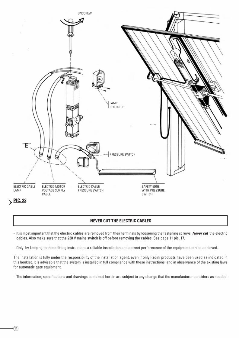
- It is most important that the electric cables are removed from their terminals by loosening the fastening screws. Never cut the electriccables. Also make sure that the 230 V mains switch is off before removing the cables. See page 11 pic. 17.
- Only by keeping to these fitting instructions a reliable installation and correct performance of the equipment can be achieved.
The installation is fully under the responsibility of the installation agent, even if only Fadini products have been used as indicated inthis booklet. It is advisable that the system is installed in full compliance with these instructions and in observance of the existing lawsfor automatic gate equipment.
- The information, specifications and drawings contained herein are subject to any change that the manufacturer considers as needed.
NEVER CUT THE ELECTRIC CABLES
UNSCREW
LAMPREFLECTOR
ELECTRIC CABLELAMP
PRESSURE SWITCH
ELECTRIC MOTORVOLTAGE SUPPLYCABLE
ELECTRIC CABLEPRESSURE SWITCH
SAFETY EDGEWITH PRESSURESWITCH
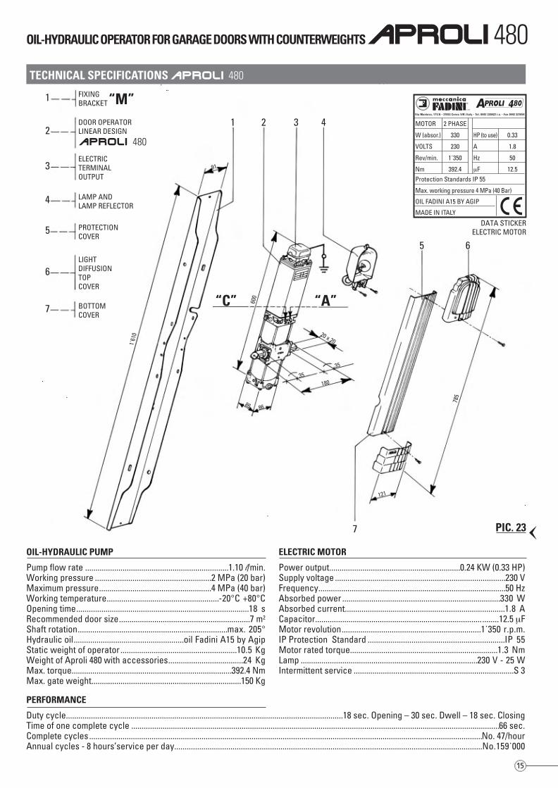
PERFORMANCE
Duty cycle.....................................................................................................................................18 sec. Opening – 30 sec. Dwell – 18 sec. ClosingTime of one complete cycle .................................................................................................................................................................................66 sec.Complete cycles.............................................................................................................................................................................................No. 47/hourAnnual cycles - 8 hours’service per day....................................................................................................................................................No.159˙000
OIL-HYDRAULIC PUMP
Pump flow rate .....................................................................1.10 l/min.Working pressure ........................................................2 MPa (20 bar)Maximum pressure......................................................4 MPa (40 bar)Working temperature......................................................-20°C +80°COpening time...................................................................................18 sRecommended door size...............................................................7 m2
Shaft rotation........................................................................max. 205°Hydraulic oil.....................................................oil Fadini A15 by AgipStatic weight of operator ........................................................10.5 KgWeight of Aproli 480 with accessories....................................24 KgMax. torque.............................................................................392.4 NmMax. gate weight........................................................................150 Kg
ELECTRIC MOTOR
Power output...............................................................0.24 KW (0.33 HP)Supply voltage ..................................................................................230 VFrequency..........................................................................................50 HzAbsorbed power ............................................................................330 WAbsorbed current.............................................................................1.8 ACapacitor........................................................................................12.5 µFMotor revolution...................................................................1˙350 r.p.m.IP Protection Standard ..................................................................IP 55Motor rated torque.......................................................................1.3 NmLamp .....................................................................................230 V - 25 WIntermittent service .............................................................................S 3
TECHNICAL SPECIFICATIONS APROLI 480
OIL-HYDRAULIC OPERATOR FOR GARAGE DOORS WITH COUNTERWEIGHTS APROLI 480
1 FIXINGBRACKET“M”
2DOOR OPERATORLINEAR DESIGN
MOTOR
W (absor.)
VOLTS
Rev/min.
Nm
2 PHASE
330
230
1˙350
392.4Protection Standards IP 55
Max. working pressure 4 MPa (40 Bar)
OIL FADINI A15 BY AGIP
MADE IN ITALY
Via Mantova, 177/A - 37053 Cerea (VR) Italy - Tel. 0442 330422 r.a. - Fax 0442 331054
®
s.n.c.
HP (to use)
A
Hz
µF
0.33
1.8
50
12.5
APROLI 480
APROLI 480
3ELECTRICTERMINALOUTPUT
4 LAMP ANDLAMP REFLECTOR
5 PROTECTIONCOVER
6LIGHTDIFFUSIONTOPCOVER
7 BOTTOMCOVER
1 2 3 4
5 6
7
121
785
86
35
86
600
35
180
20 x 20
91
1˙61
0
“C” “A”
DATA STICKERELECTRIC MOTOR
“E”
14 15
PIC. 22
PIC. 23
- It is most important that the electric cables are removed from their terminals by loosening the fastening screws. Never cut the electriccables. Also make sure that the 230 V mains switch is off before removing the cables. See page 11 pic. 17.
- Only by keeping to these fitting instructions a reliable installation and correct performance of the equipment can be achieved.
The installation is fully under the responsibility of the installation agent, even if only Fadini products have been used as indicated inthis booklet. It is advisable that the system is installed in full compliance with these instructions and in observance of the existing lawsfor automatic gate equipment.
- The information, specifications and drawings contained herein are subject to any change that the manufacturer considers as needed.
NEVER CUT THE ELECTRIC CABLES
UNSCREW
LAMPREFLECTOR
ELECTRIC CABLELAMP
PRESSURE SWITCH
ELECTRIC MOTORVOLTAGE SUPPLYCABLE
ELECTRIC CABLEPRESSURE SWITCH
SAFETY EDGEWITH PRESSURESWITCH
PERFORMANCE
Duty cycle.....................................................................................................................................18 sec. Opening – 30 sec. Dwell – 18 sec. ClosingTime of one complete cycle .................................................................................................................................................................................66 sec.Complete cycles.............................................................................................................................................................................................No. 47/hourAnnual cycles - 8 hours’service per day....................................................................................................................................................No.159˙000
OIL-HYDRAULIC PUMP
Pump flow rate .....................................................................1.10 l/min.Working pressure ........................................................2 MPa (20 bar)Maximum pressure......................................................4 MPa (40 bar)Working temperature......................................................-20°C +80°COpening time...................................................................................18 sRecommended door size...............................................................7 m2
Shaft rotation........................................................................max. 205°Hydraulic oil.....................................................oil Fadini A15 by AgipStatic weight of operator ........................................................10.5 KgWeight of Aproli 480 with accessories....................................24 KgMax. torque.............................................................................392.4 NmMax. gate weight........................................................................150 Kg
ELECTRIC MOTOR
Power output...............................................................0.24 KW (0.33 HP)Supply voltage ..................................................................................230 VFrequency..........................................................................................50 HzAbsorbed power ............................................................................330 WAbsorbed current.............................................................................1.8 ACapacitor........................................................................................12.5 µFMotor revolution...................................................................1˙350 r.p.m.IP Protection Standard ..................................................................IP 55Motor rated torque.......................................................................1.3 NmLamp .....................................................................................230 V - 25 WIntermittent service .............................................................................S 3
TECHNICAL SPECIFICATIONS APROLI 480
OIL-HYDRAULIC OPERATOR FOR GARAGE DOORS WITH COUNTERWEIGHTS APROLI 480
1 FIXINGBRACKET“M”
2DOOR OPERATORLINEAR DESIGN
MOTOR
W (absor.)
VOLTS
Rev/min.
Nm
2 PHASE
330
230
1˙350
392.4Protection Standards IP 55
Max. working pressure 4 MPa (40 Bar)
OIL FADINI A15 BY AGIP
MADE IN ITALY
Via Mantova, 177/A - 37053 Cerea (VR) Italy - Tel. 0442 330422 r.a. - Fax 0442 331054
®
s.n.c.
HP (to use)
A
Hz
µF
0.33
1.8
50
12.5
APROLI 480
APROLI 480
3ELECTRICTERMINALOUTPUT
4 LAMP ANDLAMP REFLECTOR
5 PROTECTIONCOVER
6LIGHTDIFFUSIONTOPCOVER
7 BOTTOMCOVER
1 2 3 4
5 6
7
121
785
86
35
86
600
35
180
20 x 20
91
1˙61
0
“C” “A”
DATA STICKERELECTRIC MOTOR
“E”
14 15
PIC. 22
PIC. 23
Via Mantova, 177/A - 37053 Cerea (Verona) Italy - Tel. +39 0442 330422 r.a. - Fax +39 0442 331054 - e-mail: [email protected] - www.fadini.net
EUROPEAN MARK CERTIFYING CONFORMITYTO THE ESSENTIAL REQUIREMENTS OF THESTANDARDS 98/37/EC
• DECLARATION OF CONFORMITY• SAFETY NORMS• EN 12453, EN 12445 STANDARDS• CEI EN 60204-1 STANDARDS• WARRANTY CERTIFICATE ON THE CUSTOMER’S REQUEST
The growth of MECCANICA FADINI has always been based on the development of guaranteed products thanks to our “TOTAL QUALITYCONTROL” system which ensures constant quality standards, updated knowledge of the European Standards and compliance withtheir requirements, in view of an ever increasing process of improvement.
The “CE” mark certifies that the operator conforms to the essential requirements of the European Directive art. 10 EEC 73/23, in relationto the manufacturer’s declaration for the supplied items, in compliance with the body of the regulations ISO 9000= UNI EN 29000.Automation in conformity to EN 12453, EN 12445 safety standards.
10-2
005
IMPORTANT WARNING NOTES- Before installing the equipment carry out a Risk Analysis and fit any required device in compliance with EN 12445 and EN 12453 Safety Norms.- It is recommended to keep to the instructions here outlined. Check the specifications on the motor sticker with your mains supply.- Dispose properly of the packaging: cardboard, nylon, polystyrene, through specializing companies.- Should the operator be removed, do not cut the electric cable. This must be properly removed from the terminal board in the junction box.- Switch off the mains switch before removing the junction box cover where the electric cable is terminated.- All the system must be earthed by using the yellow/green wire, marked by its specific symbol.- It is recommended to read the regulations, suggestions and remarks quoted in the booklet “Safety Norms”.
CHECKING AND MAINTENANCE:To achieve an optimum performance and longer life of the equipment and in observance of the safety regulations, it is recommended that inspectionsand proper maintenance are made by qualified technicians to the whole installation ie, both the mechanical and electronic parts, as well as wiring:- Mechanical parts: maintenance every 6 months approx.- Eletronic apparatus and safety equipment: maintenance every month.
®
INSTALLATION MANUALGB
AUTOMATIC GATE MANUFACTURERS
®
s.n.c.
The manufacturers reserve the right to change the products without any previousnotice and are not liable for possible damages to people and properties.
Distributor’s box
Made in Italy
®


![· 2018. 12. 7. · gortina agip belluno 1 (2614 m) austria lire 500] permessi agip 1955-1965 permessi agip 1973-1984 sondaggi esplorativi agip fig. erba scala l:l.ooo.ooo gerola](https://img.pdfslide.net/doc/110x75/60e1ea431e9a5526987cd1a9/2018-12-7-gortina-agip-belluno-1-2614-m-austria-lire-500-permessi-agip-1955-1965.jpg)