Embed Size (px)
Citation preview

ALPINE MRV-M1200 68-29530Z91-A (EN/FR/ES)
EN
FR
ES
FOR CAR USE ONLY/POUR APPLICATION AUTOMOBILE/PARA USO EN AUTOMÓVILES
• OWNER’S MANUALPlease read before using this equipment.
• MODE D’EMPLOIVeuillez lire avant d’utiliser cet appareil.
• MANUAL DE OPERACIÓNLéalo antes de utilizar este equipo.
ALPINE ELECTRONICS MARKETING, INC.1-7, Yukigaya-Otsukamachi, Ota-ku,
Tokyo 145-0067, JAPANPhone: 03-5499-4531
ALPINE ELECTRONICS OF AMERICA, INC.19145 Gramercy Place, Torrance,
California 90501, U.S.A.Phone 1-800-ALPINE-1 (1-800-257-4631)
ALPINE ELECTRONICS OF AUSTRALIA PTY. LTD.161-165 Princes Highway, Hallam
Victoria 3803, AustraliaPhone 03-8787-1200
ALPINE ELECTRONICS GmbHWilhelm-Wagenfeld-Str. 1-3,80807 München, Germany
Phone 089-32 42 640
ALPINE ELECTRONICS OF U.K. LTD.Alpine House
Fletchamstead Highway, Coventry CV4 9TW, U.K.www.alpine.co.uk
ALPINE ELECTRONICS France S.A.R.L.184 allée des ErablesCS 52016 – Villepinte
95 945 Roissy CDG cedexFRANCE
Phone : + 33(0)1 48 63 89 89
ALPINE ITALIA S.p.A.Viale Cristoforo Colombo, 8
20090 Trezzano sul Naviglio MI, ItalyPhone +39 02 484781
ALPINE ELECTRONICS DE ESPAÑA, S.A.Portal de Gamarra 36, Pabellón, 32
01013 Vitoria (Alava)-APDO 133, SpainPhone 945-283588
MRV-M1200MONO POWER AMPLIFIER
JEIL Moon Hwa Co.18-6, 3Ga, Pil_dong, Jung_gu, Seoul, Korea
Designed by ALPINE JapanPrinted in Korea
68-29530Z91-A (Y-A5)M3514596010

ALPINE MRV-M1200 68-29530Z91-A (EN/FR/ES)

ALPINE MRV-M1200 68-29530Z91-A (EN/FR/ES)
1-EN
EN
FR
ES
English
CONTENTSWARNING................................................................................1SERVICE CARE .......................................................................2ACCESSORIES ........................................................................2INSTALLATION .......................................................................3ATTACHING THE TERMINAL COVERS.............................3CONNECTIONS .....................................................................4CONNECTION CHECK LIST ................................................8SWITCH SETTINGS ...............................................................9SYSTEM DIAGRAMS ......................................................... 11SPECIFICATIONS ................................................................ 14
WARNING
Points to Observe for Safe Usage
Read this manual carefully before using the system components. They contain instructions on how to use this product in a safe and effective manner. Alpine cannot be responsible for problems resulting from failure to observe the instructions in this manual.
WARNINGThis symbol means important instructions.
Failure to heed them can result in serious
injury or death.
DO NOT OPERATE ANY FUNCTION THAT TAKES YOUR ATTENTION AWAY FROM SAFELY DRIVING YOUR VEHICLE.Any function that requires your prolonged attention should only be performed after coming to a complete stop. Always stop the vehicle in a safe location before performing these functions. Failure to do so may result in an accident.
KEEP THE VOLUME AT A LEVEL WHERE YOU CAN STILL HEAR OUTSIDE NOISES WHILE DRIVING.Excessive volume levels that obscure sounds such as emergency vehicle sirens or road warning signals (train crossings, etc.) can be dangerous and may result in an accident. LISTENING AT LOUD VOLUME LEVELS IN A CAR MAY ALSO CAUSE HEARING DAMAGE.
DO NOT DISASSEMBLE OR ALTER.Doing so may result in an accident, fire or electric shock.
USE THIS PRODUCT FOR MOBILE 12V APPLICATIONS.Use for other than its designed application may result in fire, electric shock or other injury.
USE THE CORRECT AMPERE RATING WHEN REPLACING FUSES.Failure to do so may result in fire or electric shock.
DO NOT BLOCK VENTS OR RADIATOR PANELS.Doing so may cause heat to build up inside and may result in fire.
MAKE THE CORRECT CONNECTIONS.Failure to make the proper connections may result in fire or product damage.
USE ONLY IN CARS WITH A 12 VOLT NEGATIVE GROUND. (Check with your dealer if you are not sure.) Failure to do so may result in fire, etc.
BEFORE WIRING, DISCONNECT THE CABLE FROM THE NEGATIVE BATTERY TERMINAL.Failure to do so may result in electric shock or injury due to electrical shorts.
DO NOT ALLOW CABLES TO BECOME ENTANGLED IN SURROUNDING OBJECTS.Arrange wiring and cables in compliance with the manual to prevent obstructions when driving. Cables or wiring that obstruct or hang up on places such as the steering wheel, gear lever, brake pedals, etc. can be extremely hazardous.
DO NOT SPLICE INTO ELECTRICAL CABLES.Never cut away cable insulation to supply power to other equipment. Doing so will exceed the current carrying capacity of the wire and result in fire or electric shock.
DO NOT DAMAGE PIPE OR WIRING WHEN DRILLING HOLES.When drilling holes in the chassis for installation, take precautions so as not to contact, damage or obstruct pipes, fuel lines, tanks or electrical wiring. Failure to take such precautions may result in fire.

ALPINE MRV-M1200 68-29530Z91-A (EN/FR/ES)
2-EN
INSTDue to thconsideris in operbe mouncirculatioalternateauthorize
1. Usingscrew
2. Make surfacdrillin
3. Drill t4. Positio
and se
Holes
Chassis
NOTE:• To secu
alreadyvehicleon the groundterminagroundas possnoise.
5. AttachAttachinstruetc., bScrew
DO NOT USE BOLTS OR NUTS IN THE BRAKE OR STEERING SYSTEMS TO MAKE GROUND CONNECTIONS.Bolts or nuts used for the brake or steering systems (or any other safety-related system), or tanks should NEVER be used for installations or ground connections. Using such parts could disable control of the vehicle and cause fire etc.
KEEP SMALL OBJECTS SUCH AS BATTERIES OUT OF THE REACH OF CHILDREN.Swallowing them may result in serious injury. If swallowed, consult a physician immediately.
CAUTIONThis symbol means important instructions.
Failure to heed them can result in injury or
property damages.
HALT USE IMMEDIATELY IF A PROBLEM APPEARS.Failure to do so may cause personal injury or damage to the product. Return it to your authorized Alpine dealer or the nearest Alpine Service Center for repairing.
HAVE THE WIRING AND INSTALLATION DONE BY EXPERTS.The wiring and installation of this unit requires special technical skill and experience. To ensure safety, always contact the dealer where you purchased this product to have the work done.
USE SPECIFIED ACCESSORY PARTS AND INSTALL THEM SECURELY.Be sure to use only the specified accessory parts. Use of other than designated parts may damage this unit internally or may not securely install the unit in place. This may cause parts to become loose resulting in hazards or product failure.
ARRANGE THE WIRING SO IT IS NOT CRIMPED OR PINCHED BY A SHARP METAL EDGE.Route the cables and wiring away from moving parts (like the seat rails) or sharp or pointed edges. This will prevent crimping and damage to the wiring. If wiring passes through a hole in metal, use a rubber grommet to prevent the wire’s insulation from being cut by the metal edge of the hole.
DO NOT INSTALL IN LOCATIONS WITH HIGH MOISTURE OR DUST.Avoid installing the unit in locations with high incidence of moisture or dust. Moisture or dust that penetrates into this unit may result in product failure.
SERVICE CARE IMPORTANT NOTICE
This Amplifier has been type tested and found to comply with the limits for a Class B computing device in accordance with the specifications in Subpart J of Part 15 of FCC Rules. This equipment generates and uses radio frequency energy, and it must be installed and used properly in accordance with the manufacturer’s instructions.
SERIAL NUMBER: INSTALLATION DATE: INSTALLATION TECHNICIAN: PLACE OF PURCHASE:
IMPORTANTPlease record the serial number of your unit in the space provided here and keep it as a permanent record. The serial number plate is located on the rear of the unit.
For European CustomersShould you have any questions about warranty, please consult your store of purchase.
For Customers in other Countries
IMPORTANT NOTICECustomers who purchase the product with which this notice is packaged, and who make this purchase in countries other than the United States of America and Canada, please contact your dealer for information regarding warranty coverage.
ACCESSORIES• Self-Tapping Screw (M4 × 20) ......................................4• Terminal Cover ..........................................................1 SET• Speaker Input Connector ..............................................1• Hexagon Wrench ..............................................................1• Remote Bass Control Unit .....................................1 SET
– Connection Cable (5 m)..............................................1 – Self-Tapping Screw (M4 × 12)...................................4

ALPINE MRV-M1200 68-29530Z91-A (EN/FR/ES)
3-EN
EN
FR
ES
INSTALLATIONDue to the high power output of the MRV-M1200 considerable heat is produced when the amplifier is in operation. For this reason, the amplifier should be mounted in a location which will allow for free circulation of air, such as inside the trunk. For alternate installation locations, please contact your authorized Alpine dealer.
1. Using the amplifier as a template, mark the four screw locations.
2. Make sure there are no objects behind the surface that may become damaged during drilling.
3. Drill the screw holes.4. Position the MRV-M1200 over the screw holes,
and secure with four self-tapping screws.
Self-Tapping Screws (M4 × 20)
Holes
HolesChassis
Ground Lead
NOTE:• To securely connect the ground lead, use an
already installed screw on a metal part of the vehicle (marked ( )) or a clean, bare metal spot on the vehicle’s chassis. Be sure this is a good ground by checking continuity to the battery (–) terminal. Connect all equipment to the same ground point while keeping wire length as short as possible. These procedures will help eliminate noise.
5. Attach the Remote Bass Control Unit.Attach the Remote Bass Control Unit under the instrument panel or side of the front console, etc., by using the four supplied Self-Tapping Screws.
Self-Tapping Screws (M4 × 12)
CAUTIONDO NOT ALLOW CABLES TO BECOME ENTANGLED IN SURROUNDING OBJECTS. Cables or wiring that obstruct or hang up on places such as the steering wheel, gear lever, brake pedals, etc. can be extremely hazardous.
ATTACHING THE TERMINAL COVERS
Attach the terminal covers (included) after connections and confirmation of correct operation.Attaching the terminal covers will improve the appearance of the unit.How to attach the terminal covers:Attach the terminal covers to the main unit.
Terminal Covers
CAUTIONDo not lift or carry the unit by the attached terminal covers.
und to ing s in
pment y, and it ordance
nit in
e is
anty,
which
d States r dealer
ge.
..............4
......1 SET
..............1
..............1
......1 SET
..............1
..............4

ALPINE MRV-M1200 68-29530Z91-A (EN/FR/ES)
4-EN
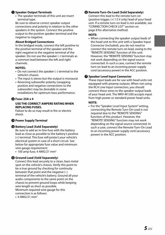
Speak• The
termBe surconnespeakoutpunegatAbouIn thethe poright nspeaka comchannNOTE• Do n
vehi• The • Reve
posisubwinsta
Fuse:USE TREPLAFailureshock
Powe
BatteBe surlead a(+) terelectrbelowwire g• 100
GrounConnespot obe a tbetweterminaudiochasswire leMinimconne• 4 AW
CONNECTIONS
Be sure to add an in-line fuse with the battery lead as close as possible to the battery’s positive (+) terminal.
Before making connections, be sure to turn the power off to all audio components. Connect the battery lead from the amp directly to the positive (+) terminal of the vehicle’s battery with appropriate in-line vehicle’s fuse (see Battery Lead section). Do not connect this lead to the vehicle’s fuse block.To prevent external noise from entering the audio system• Locate the unit and route the leads at least 10 cm
(4”) away from the vehicle’s harness.• Keep the battery power leads as far away from
other leads as possible.• Connect the ground lead securely to a bare metal
spot (remove any paint or grease if necessary) of the vehicle’s chassis.
• If you add an optional noise suppressor, connect it as far away from the unit as possible. Your Alpine dealer carries various noise suppressors, contact them for further information.
• Your Alpine dealer knows best about noise prevention measures so consult your dealer for further information.
ALPINE MRV-M1200 68-29530Z91-A (EN/FR/ES)
5-EN
EN
FR
ES
Speaker Output Terminals• The speaker terminals of this unit are insert
terminal type.Be sure to observe correct speaker output connections and polarity in relation to the other speakers in the system. Connect the positive output to the positive speaker terminal and the negative to negative. About Bridged ConnectionsIn the bridged mode, connect the left positive to the positive terminal of the speaker and the right negative to the negative terminal of the speaker. Do not use the speaker (–) terminals as a common lead between the left and right channels.NOTES:• Do not connect the speaker (–) terminal to the
vehicle’s chassis.• The input is stereo but the output is monaural.• Reversing subwoofer polarity (swapping
positive and negative connections to the subwoofer) may be desirable in some installations for optimum bass performance.
Fuse: 25A x 4USE THE CORRECT AMPERE RATING WHEN REPLACING FUSES.Failure to do so may result in fire or electric shock.
Power Supply Terminal
Battery Lead (Sold Separately)Be sure to add an in-line fuse with the battery lead as close as possible to the battery’s positive (+) terminal. This fuse will protect your vehicle’s electrical system in case of a short circuit. See below for appropriate fuse value and minimum wire gauge requirement:• 100 amp fuse, 4 AWG/21 mm2
Ground Lead (Sold Separately)Connect this lead securely to a clean, bare metal spot on the vehicle’s chassis. Verify this point to be a true ground by checking for continuity between that point and the negative (–) terminal of the vehicle’s battery. Ground all your audio components to the same point on the chassis to prevent ground loops while keeping wire length as short as possible.Minimum required wire gauge for this connection is as follows:• 4 AWG/21 mm2
Remote Turn-On Lead (Sold Separately)Connect this lead to the remote turn-on (positive trigger, (+) 12 V only) lead of your head unit. If a remote turn-on lead is not available, see “CONNECTION CHECK LIST” section on page 8 for alternative method.NOTE:• When connecting the speaker output leads of
the head unit to this unit with a Speaker Input Connector (included), you do not need to connect the remote turn-on lead, owing to the “REMOTE SENSING” function of this unit. However, the “REMOTE SENSING” function may not work depending on the signal source connected. In such a case, connect the remote turn-on lead to an incoming power supply cord (accessory power) in the ACC position.
Speaker Level Input ConnectorThese input leads are for use with head units not equipped with preamp outputs. When not using the RCA Line Input connectors, you should connect these wires to the speaker output leads of your head unit. The MRV-M1200 accepts input from high power or standard power head units.NOTE:• For the “Speaker Level Input System” setting,
connecting the Remote Turn-On Lead is not required due to the “REMOTE SENSING” function of this product. However, the “REMOTE SENSING” function may not work depending on the signal source connected. In such a case, connect the Remote Turn-On Lead to an incoming power supply cord (accessory power) in the ACC position.
onnect ur
essors,
e ler for

ALPINE MRV-M1200 68-29530Z91-A (EN/FR/ES)
6-EN
2. Remoleads
NOTES:• If lengt
connecor soun
• On theelectric
3. TightehexagBeforshrinexten
W
NOTES:• Use on• For safe• To prev
droppicarry th
RCA Input JacksConnect these jacks to the line out leads on your head unit using RCA extension cables (sold separately). Be sure to observe correct channel connections; Left to Left and Right to Right.NOTE:• Use either RCA line level or speaker level
inputs. Do not connect both at the same time.
Pre-Out JacksThese jacks provide a line level output. This is an ideal output for driving a second subwoofer amp. This output is full-range, and is not affected by the crossover.
Remote Bass Control Jack
Connection Cable
Remote Bass Control UnitThe Remote Bass Control Unit adjusts the output level remotely. This is not to replace appropriate gain level setting between the amplifier and head unit.
Speaker Input Connector
Front Left Speaker (White (+))
Front Left Speaker (White/Black (–))
Front Right Speaker (Gray (+))
Front Right Speaker (Gray/Black (–))
Rear Right Speaker (Violet/Black (–))
Rear Right Speaker (Violet (+))
Rear Left Speaker (Green/Black (–))
Rear Left Speaker (Green (+))
CAUTIONAbout Power supply wiresIf the length of the power and ground cables exceed 1 m, or if you connect more than one amplifier, a distribution block should be used. See below for wire gauge recommendations for distribution block connection to battery and ground (depends upon wire length necessary): 2 AWG (33 mm2) or 1/0 AWG (53 mm2)
MRV-M1200
BATTERY GROUND
4 AWG (21 mm2)
Distribution block
1 m (Max.)
2 AWG (33 mm2) or 1/0 AWG (53 mm2)
To vehicle’s battery
To vehicle’s chassis
Connect all equipment to the same ground point while keeping wire length as short as possible.
Ensure that you install a correctly-rated in-line fuse on the power cable near the battery positive post.Cautions on wire lead connectionsWhen using third-party wire cables (power supply wire), use the supplied screws to simplify the connection. Refer to the description below for the proper procedure. If you are in doubt about how to make this connection, consult your dealer.
1. Check the wire size.• Required Wire Size
– Battery Lead/Ground Lead ....4 AWG (21 mm2) – Remote Turn-On Lead .............12 AWG (3 mm2) – Speaker Output Lead ................ 8 AWG (8 mm2)
• If the wire gauge used is unknown, ask your dealer.
ALPINE MRV-M1200 68-29530Z91-A (EN/FR/ES)
7-EN
EN
FR
ES
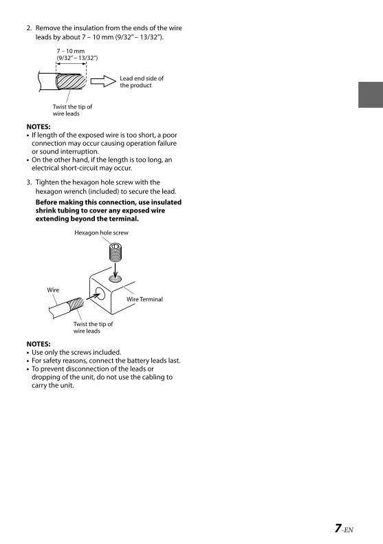
2. Remove the insulation from the ends of the wire leads by about 7 – 10 mm (9/32” – 13/32”).
Lead end side of the product
Twist the tip of wire leads
7 – 10 mm (9/32” – 13/32”)
NOTES:• If length of the exposed wire is too short, a poor
connection may occur causing operation failure or sound interruption.
• On the other hand, if the length is too long, an electrical short-circuit may occur.
3. Tighten the hexagon hole screw with the hexagon wrench (included) to secure the lead.Before making this connection, use insulated shrink tubing to cover any exposed wire extending beyond the terminal.
Hexagon hole screw
Wire Terminal
Twist the tip of wire leads
Wire
NOTES:• Use only the screws included.• For safety reasons, connect the battery leads last.• To prevent disconnection of the leads or
dropping of the unit, do not use the cabling to carry the unit.
es ne ed. See r d
ary):
mm2) or 3 mm2)
nt while
ine fuse ve post.
supply he
for the t how to
21 mm2)(3 mm2)(8 mm2)
k your
ALPINE MRV-M1200 68-29530Z91-A (EN/FR/ES)
8-EN
SWINOTE:• Before
the powperpen
InputSet thpositiincreadistorthe outhe amspeakslightachiev
CrossFILTEUse thfreque
Bass EAdd ayour b
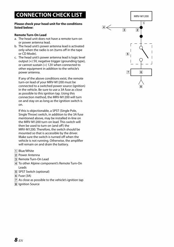
CONNECTION CHECK LISTPlease check your head unit for the conditions listed below:
Remote Turn-On Leada. The head unit does not have a remote turn-on
or power antenna lead.b. The head unit’s power antenna lead is activated
only when the radio is on (turns off in the tape or CD Mode).
c. The head unit’s power antenna lead is logic level output (+) 5V, negative trigger (grounding type), or cannot sustain (+) 12V when connected to other equipment in addition to the vehicle’s power antenna.
If any of the above conditions exist, the remote turn-on lead of your MRV-M1200 must be connected to a switched power source (ignition) in the vehicle. Be sure to use a 3A fuse as close as possible to this ignition tap. Using this connection method, the MRV-M1200 will turn on and stay on as long as the ignition switch is on.
If this is objectionable, a SPST (Single Pole, Single Throw) switch, in addition to the 3A fuse mentioned above, may be installed in-line on the MRV-M1200 turn-on lead. This switch will then be used to turn on (and off ) the MRV-M1200. Therefore, the switch should be mounted so that is accessible by the driver. Make sure the switch is turned off when the vehicle is not running. Otherwise, the amplifier will remain on and drain the battery.
Blue/White Power Antenna Remote Turn-On Lead To other Alpine component’s Remote Turn-On Leads
SPST Switch (optional) Fuse (3A) As close as possible to the vehicle’s ignition tap Ignition Source
MRV-M1200

ALPINE MRV-M1200 68-29530Z91-A (EN/FR/ES)
9-EN
EN
FR
ES
SWITCH SETTINGSNOTE:• Before switching each Selector Switch, turn off
the power and insert a small screwdriver, etc., perpendicularly to the Switch.
Input Gain Adjustment ControlSet the MRV-M1200 input gain to the minimum position. Using a dynamic CD as a source, increase the head unit volume until the output distorts. Then, reduce the volume 1 step (or until the output is no longer distorted). Now, increase the amplifier gain until the sound from the speakers becomes distorted. Reduce the gain slightly so the sound is no longer distorted to achieve the optimum gain setting.
Crossover Frequency Adjustment Knob (LP FILTER)Use this control to adjust the crossover frequency between 50 to 400 Hz.
Bass EQ Adjustment KnobAdd a 50 Hz bass boost up to +12 dB to tune your bass response.
ALPINE MRV-M1200 68-29530Z91-A (EN/FR/ES)
10-EN
SYSTWhen yobefore co
Subw Head Subw RCA E Y-Ada
TYPIC
1 Subw
Conne
1 FocoreqthfusoResu
2 If cInpsigInsdif
ex Sp F RC S
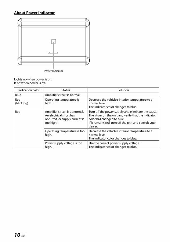
About Power Indicator
Power Indicator
Lights up when power is on.Is off when power is off.
Indication color Status SolutionBlue Amplifier circuit is normal.Red(blinking)
Operating temperature is high.
Decrease the vehicle’s interior temperature to a normal level.The indicator color changes to blue.
Red Amplifier circuit is abnormal. An electrical short has occurred, or supply current is too high.
Turn off the power supply and eliminate the cause.Then turn on the unit and verify that the indicator color has changed to blue.If it remains red, turn off the unit and consult your dealer.
Operating temperature is too high.
Decrease the vehicle’s interior temperature to a normal level.The indicator color changes to blue.
Power supply voltage is too high.
Use the correct power supply voltage.The indicator color changes to blue.

ALPINE MRV-M1200 68-29530Z91-A (EN/FR/ES)
11-EN
EN
FR
ES
SYSTEM DIAGRAMSWhen you connect one or multiple subwoofers, please take care to configure the correct total impedance before connecting to subwoofer(s) to the amplifier.
Subwoofer Head Unit, etc. Subwoofer Output RCA Extension Cable (Sold Separately) Y-Adapter (Sold Separately)
TYPICAL SYSTEM CONNECTIONS
1 Subwoofer System
White Violet/Black
Gray/Black Green
Green/Black
Violet
Violet/Black
White/Black Violet
Gray
Gray Green/Black
White/Black
Gray/Black Green
White
Connecting to the Speaker Level Input System
1 For the “Speaker Level Input System” setting, connecting the Remote Turn-On Lead is not required due to the “REMOTE SENSING” function of this product. However, the “REMOTE SENSING” function may not work depending on the signal source connected. In such a case, connect the Remote Turn-On Lead to an incoming power supply cord (accessory power) in the ACC position.
2 If connecting both Speaker Input Leads and RCA Inputs at the same time, do not connect both signals to the same input channel of the amplifier. Instead, be sure to connect each pair of inputs to a different Input channel pair.
example; Speaker Input Leads: FL/FR to CH1/CH2, RL/RR to CH3/CH4 RCA Inputs: SUBWL/SUBWR to SUBWL/SUBWR
to a
e cause.dicator
lt your
to a

ALPINE MRV-M1200 68-29530Z91-A (EN/FR/ES)
12-EN
MULT
Import
NOTE:• Low ou
line ou
2 Subwoofer System (MONO)
White Violet/Black
Gray/Black Green
Green/Black
Violet
Violet/Black
White/Black Violet
Gray
Gray Green/Black
White/Black
Gray/Black Green
White
Connecting to the Speaker Level Input System
ALPINE MRV-M1200 68-29530Z91-A (EN/FR/ES)
13-EN
EN
FR
ES
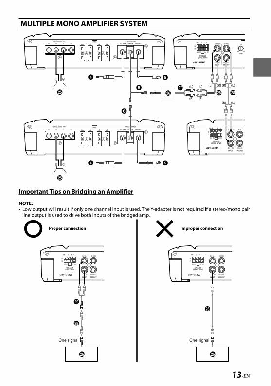
MULTIPLE MONO AMPLIFIER SYSTEM
Important Tips on Bridging an Amplifier
NOTE:• Low output will result if only one channel input is used. The Y-adapter is not required if a stereo/mono pair
line output is used to drive both inputs of the bridged amp.
Proper connection
One signal One signal
Improper connection
ack
ck
k
ack
ALPINE MRV-M1200 68-29530Z91-A (EN/FR/ES)
14-EN
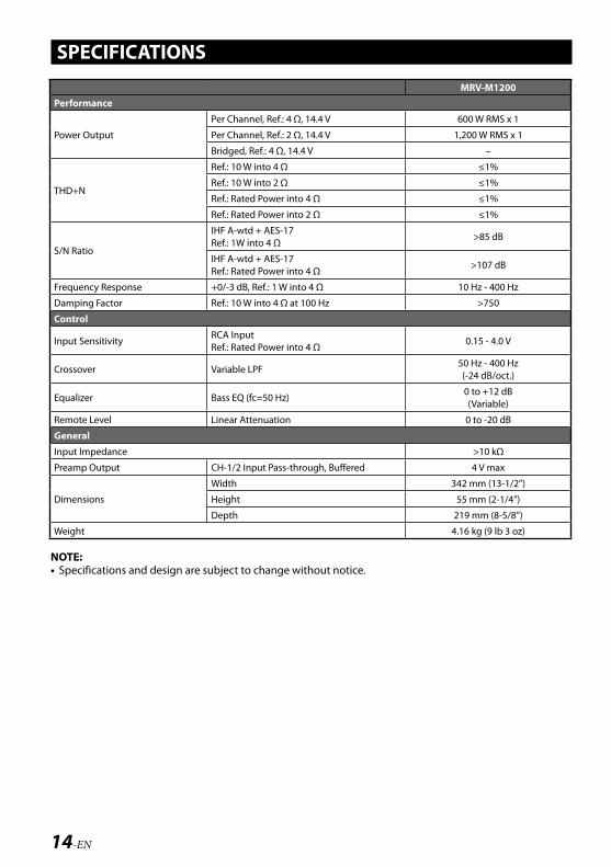
SPECIFICATIONS
MRV-M1200Performance
Power Output
Per Channel, Ref.: 4 Ω, 14.4 V 600 W RMS x 1
Per Channel, Ref.: 2 Ω, 14.4 V 1,200 W RMS x 1
Bridged, Ref.: 4 Ω, 14.4 V –
THD+N
Ref.: 10 W into 4 Ω ≤1%
Ref.: 10 W into 2 Ω ≤1%
Ref.: Rated Power into 4 Ω ≤1%
Ref.: Rated Power into 2 Ω ≤1%
S/N Ratio
IHF A-wtd + AES-17Ref.: 1W into 4 Ω
>85 dB
IHF A-wtd + AES-17Ref.: Rated Power into 4 Ω
>107 dB
Frequency Response +0/-3 dB, Ref.: 1 W into 4 Ω 10 Hz - 400 Hz
Damping Factor Ref.: 10 W into 4 Ω at 100 Hz >750
Control
Input SensitivityRCA InputRef.: Rated Power into 4 Ω
0.15 - 4.0 V
Crossover Variable LPF 50 Hz - 400 Hz(-24 dB/oct.)
Equalizer Bass EQ (fc=50 Hz)0 to +12 dB(Variable)
Remote Level Linear Attenuation 0 to -20 dB
General
Input Impedance >10 kΩ
Preamp Output CH-1/2 Input Pass-through, Buffered 4 V max
Dimensions
Width 342 mm (13-1/2”)
Height 55 mm (2-1/4”)
Depth 219 mm (8-5/8”)
Weight 4.16 kg (9 lb 3 oz)
NOTE:• Specifications and design are subject to change without notice.