Embed Size (px)
DESCRIPTION
User's Guide
Citation preview

omega.com e-mail: [email protected]
For latest product manuals:omegamanual.info
User’s Guide
D1000 SeriesDigital Transmitters
MADE IN
Shop online at

Servicing North America:U.S.A.: One Omega Drive, Box 4047ISO 9001 Certified Stamford, CT 06907-0047
Tel: (203) 359-1660 FAX: (203) 359-7700e-mail: [email protected]
Canada: 976 BergarLaval (Quebec) H7L 5A1, CanadaTel: (514) 856-6928 FAX: (514) 856-6886e-mail: [email protected]
For immediate technical or application assistance:U.S.A. and Canada: Sales Service: 1-800-826-6342 / 1-800-TC-OMEGA®
Customer Service: 1-800-622-2378 / 1-800-622-BEST®
Engineering Service: 1-800-872-9436 / 1-800-USA-WHEN®
Mexico: En Espanol: (001) 203-359-7803 e-mail: [email protected]: (001) 203-359-7807 [email protected]
Servicing Europe:Benelux: Postbus 8034, 1180 LA Amstelveen, The Netherlands
Tel: +31 (0)20 3472121 FAX: +31 (0)20 6434643Toll Free in Benelux: 0800 0993344e-mail: [email protected]
Czech Republic: Frystatska 184, 733 01 Karvina , Czech RepublicTel: +420 (0)59 6311899 FAX: +420 (0)59 6311114Toll Free: 0800-1-66342 e-mail: [email protected]
France: 11, rue Jacques Cartier, 78280 Guyancourt, FranceTel: +33 (0)1 61 37 2900 FAX: +33 (0)1 30 57 5427Toll Free in France: 0800 466 342e-mail: [email protected]
Germany/Austria: Daimlerstrasse 26, D-75392 Deckenpfronn, GermanyTel: +49 (0)7056 9398-0 FAX: +49 (0)7056 9398-29Toll Free in Germany: 0800 639 7678e-mail: [email protected]
United Kingdom: One Omega Drive, River Bend Technology CentreISO 9002 Certified Northbank, Irlam, Manchester
M44 5BD United Kingdom Tel: +44 (0)161 777 6611 FAX: +44 (0)161 777 6622Toll Free in United Kingdom: 0800-488-488e-mail: [email protected]
OMEGAnet® Online Service Internet e-mailomega.com [email protected]
It is the policy of OMEGA Engineering, Inc. to comply with all worldwide safety and EMC/EMIregulations that apply. OMEGA is constantly pursuing certification of its products to the European NewApproach Directives. OMEGA will add the CE mark to every appropriate device upon certification.The information contained in this document is believed to be correct, but OMEGA accepts no liability for anyerrors it contains, and reserves the right to alter specifications without notice.WARNING: These products are not designed for use in, and should not be used for, human applications.

D1000 SERIES USERS MANUAL
REVISED: 10/1/97
Omega EngineeringOne Omega DriveP O Box 4047Stamford, CT 06907Phone: 1-800-DAS-IEEEFax: 203-359-7990e-mail: [email protected]
The information in this publication has been carefully checked and isbelieved to be accurate; however, no responsibility is assumed for possibleinaccuracies or omissions. Applications information in this manual is in-tended as suggestions for possible use of the products and not as explicitperformance in a specific application. Specifications may be subject tochange without notice.D1000 modules are not intrinsically safe devices and should not be used inan explosive environment unless enclosed in approved explosion-proofhousings.
TABLE OF CONTENTSWarranty 4CHAPTER 1 Getting Started
Default Mode 1-1Quick Hook-Up 1-2
CHAPTER 2 Functional DescriptionBlock Diagram 2-4
CHAPTER 3 CommunicationsData Format 3-2RS-232 3-2Multi-party Connection 3-3Software Considerations 3-4Changing Baud Rate 3-5Using a Daisy-Chain With a Dumb Terminal 3-5RS-485 3-6RS-485 Multidrop System 3-8
CHAPTER 4 Command SetTable of Commands 4-6User Commands 4-7Error Messages 4-18
CHAPTER 5 Setup Information and CommandCommand Syntax 5-2Setup Hints 5-11
CHAPTER 6 Digital I/O FunctionDigital Outputs 6-1Digital Inputs 6-2Events Counter 6-3Alarm Outputs 6-4On-Off Controller 6-5Setpoint 6-9
CHAPTER 7 Power SupplyCHAPTER 8 TroubleshootingCHAPTER 9 CalibrationAppendix A (ASCII TABLE )Appendix B D1600 Data SheetAppendix C D1400 Data SheetAppendix D D1500 Data SheetAppendix E D2000 SeriesAppendix F Continuous OperationAppendix G RTS OperationAppendix H D1000/2000 Specifications
Chapter 1Getting Started
Default ModeAll D1000 modules contain an EEPROM (Electrically Erasable Program-mable Read Only Memory) to store setup information and calibrationconstants. The EEPROM replaces the usual array of switches and potsnecessary to specify baud rate, address, parity, etc. The memory isnonvolatile which means that the information is retained even if power isremoved. No batteries are used so it is never necessary to open the modulecase.
The EEPROM provides tremendous system flexibility since all of themodule’s setup parameters may be configured remotely through the com-munications port without having to physically change switch and potsettings. There is one minor drawback in using EEPROM instead ofswitches; there is no visual indication of the setup information in the module.It is impossible to tell just by looking at the module what the baud rate,address, parity and other settings are. It is difficult to establish communica-tions with a module whose address and baud rate are unknown. Toovercome this, each module has an input pin labeled DEFAULT*. Byconnecting this pin to Ground, the module is put in a known communicationssetup called Default Mode.
The Default Mode setup is: 300 baud, one start bit, eight data bits, onestop bit, no parity, any address is recognized.
Grounding the DEFAULT* pin does not change any of the setups stored inEEPROM. The setup may be read back with the Read Setup (RS) commandto determine all of the setups stored in the module. In Default Mode, allcommands are available.
A module in Default Mode will respond to any address except the sixidentified illegal values (NULL, CR, $, #, , ). A dummy address must beincluded in every command for proper responses. The ASCII value of themodule address may be read back with the RS command. An easy way todetermine the address character is to deliberately generate an errormessage. The error message outputs the module’s address directly afterthe “?” prompt.
Setup information in a module may be changed at will with the SetUp (SU)command. Baud rate and parity setups may be changed without affectingthe Default values of 300 baud and no parity. When the DEFAULT* pin isreleased, the module automatically performs a program reset and config-ures itself to the baud rate and parity stored in the setup information.
The Default Mode is intended to be used with a single module connected toa terminal or computer for the purpose of identifying and modifying setup
1-2 D1000 USERS MANUALvalues. In most cases, a module in Default Mode may not be used in a stringwith other modules.
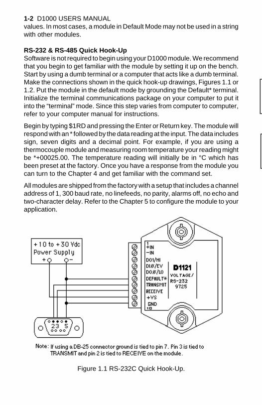
RS-232 & RS-485 Quick Hook-UpSoftware is not required to begin using your D1000 module. We recommendthat you begin to get familiar with the module by setting it up on the bench.Start by using a dumb terminal or a computer that acts like a dumb terminal.Make the connections shown in the quick hook-up drawings, Figures 1.1 or1.2. Put the module in the default mode by grounding the Default* terminal.Initialize the terminal communications package on your computer to put itinto the “terminal” mode. Since this step varies from computer to computer,refer to your computer manual for instructions.
Begin by typing $1RD and pressing the Enter or Return key. The module willrespond with an * followed by the data reading at the input. The data includessign, seven digits and a decimal point. For example, if you are using athermocouple module and measuring room temperature your reading mightbe *+00025.00. The temperature reading will initially be in °C which hasbeen preset at the factory. Once you have a response from the module youcan turn to the Chapter 4 and get familiar with the command set.
All modules are shipped from the factory with a setup that includes a channeladdress of 1, 300 baud rate, no linefeeds, no parity, alarms off, no echo andtwo-character delay. Refer to the Chapter 5 to configure the module to yourapplication.
Figure 1.1 RS-232C Quick Hook-Up.
Getting Started 1-3
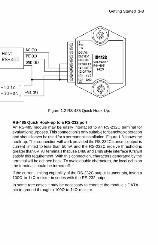
RS-485 Quick Hook-up to a RS-232 portAn RS-485 module may be easily interfaced to an RS-232C terminal forevaluation purposes. This connection is only suitable for benchtop operationand should never be used for a permanent installation. Figure 1.3 shows thehook-up. This connection will work provided the RS-232C transmit output iscurrent limited to less than 50mA and the RS-232C receive threshold isgreater than 0V. All terminals that use 1488 and 1489 style interface IC’s willsatisfy this requirement. With this connection, characters generated by theterminal will be echoed back. To avoid double characters, the local echo onthe terminal should be turned off.
If the current limiting capability of the RS-232C output is uncertain, insert a100Ω to 1kΩ resistor in series with the RS-232 output.
In some rare cases it may be necessary to connect the module’s DATApin to ground through a 100Ω to 1kΩ resistor.
Figure 1.2 RS-485 Quick Hook-Up.
1-4 D1000 USERS MANUAL
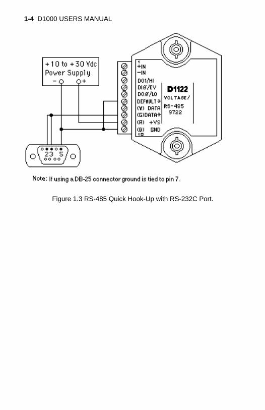
Figure 1.3 RS-485 Quick Hook-Up with RS-232C Port.
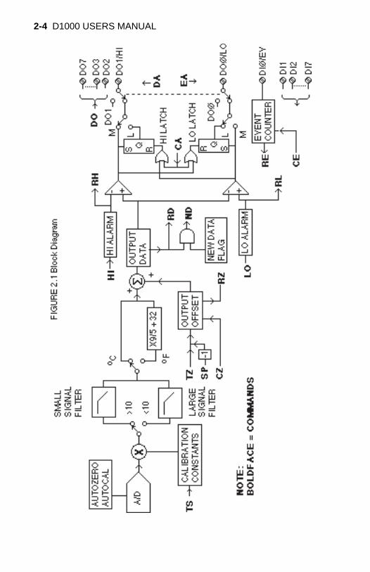
A functional diagram of a typical module is shown in Figure 2.1. It is a usefulreference that shows the data path in the module and to explain the functionof many of the module’s commands.
The first step is to acquire the sensor signal and convert it to digital data. InFigure 2.1, all the signal conditioning circuitry has been lumped into oneblock, the analog/digital converter (A/D). Autozero and autocalibration isperformed internally and is transparent to the user.
The full-scale output of the A/D converter may be trimmed using the TrimSpan (TS) command. The TS command adjusts calibration values storedinternally in the EEPROM. The TS command should only be used to trim theaccuracy of the unit with a laboratory standard reference applied to thesensor input.
The trimmed data flows into either of two digital filters. The filter selection isperformed automatically by the microprocessor after every A/D conversion.The filter selection depends on the difference of the current A/D output dataand the previous data stored in the output data register. If the least significantdecimal digit from the A/D differs from the old output data by more than 10counts, the large signal filter is selected. If the change is less than 10 counts,the small signal filter is used.
The two-filter system allows for different degrees of filtering depending onthe rate of the input change. For steady-state signals, the small-signal filteraverages out noise and small input changes to give a stable steady-stateoutput. The large-signal filter is activated by step changes or very noisy inputsignals. The time constants for the two filters can be specified independentlywith the SetUp (SU) command. The filter values are stored in nonvolatilememory. Typically, the small-signal filter is set to a larger time constant thanthe large-signal filter. This gives very good noise rejection along with fastresponse to step inputs.
The modules allow user selectable output scaling in °C or °F on temperaturedata. This selection is shown in Figure 2.1 as a switch following the digitalfilters. The default scaling in the modules is °C, but this may be convertedto °F by feeding the data through a conversion routine. The switch positionis controlled by a bit in the setup data and may be changed with the SetUp(SU) command. The scaling selection is nonvolatile. In non-temperatureapplications, °C should always be selected.
The scaled data is summed with data stored in the Output Offset Registerto obtain the final output value. The output offset is controlled by the user andhas many purposes. The data in the Output Offset Register may be used totrim any offsets caused by the input sensor. It may be used to null out
Chapter 2Functional Description
2-2 D1000 USERS MANUALundesired signal such as a tare weight. The Trim Zero (TZ) command is usedto adjust the output to any desired value by loading the appropriate value inthe offset register. The offset register data is nonvolatile.
The output offset may also be modified using the Set Point (SP) command.The data value specified by the SP command is multiplied by -1 before beingloaded into the register. The Set Point command specifies a null value thatis subtracted from the input data. The output reading becomes a deviationvalue from the downloaded setpoint. This feature is very useful in on-offcontrollers as described in Chapter 6 of this manual.
The value stored in the offset register may be read back using the Read Zero(RZ) command. Data loaded in with the SP command will be read back withthe sign changed. The output register may be reset to zero with the ClearZero (CZ) command.
The output data may be read with the Read Data (RD) command. In somecases when a computer is used as a host, the same data value may be readback several times before it is updated with a new A/D conversion. Toguarantee that the same data is not read more than once, the New Data (ND)command is used. Each time an RD or ND command is performed, the NewData Flag is cleared. The flag is set each time the output data register isloaded as the result of a new A/D conversion. The ND command waits untilthe flag is set before it outputs the data reading.
The remainder of Figure 2.1 shows several functions: a versatile alarmfunction, an event counter and general-purpose digital inputs and outputs.These functions are described in detail in Chapter 6.
The alarm section consists of two registers that are used to store high andlow alarm limit values. These registers may be down-loaded with datavalues by using the HI and LO alarm commands. The alarm values areloaded with the same data format that is used with the output data. The highand low alarm registers are nonvolatile so they will not be lost when the unitis powered down. The values held in the alarm registers may be read backat any time with the Read High (RH) and Read Low (RL) commands.
The data held in the alarm registers is continually compared with thecalculated output data. The result of the comparison is used to trip alarmsthat may be used as control outputs. The high alarm is turned on when theoutput data exceeds the high limit value. The low alarm is activated if theoutput data is less than the low alarm value. Each alarm has two userselectable modes, either Momentary (M) or Latching (L). Momentary alarmsare activated only while the alarm condition is met; if the output data returnswithin limits, the alarm is turned off. Conversely, when latching alarms areactivated, they remain on even if the output data returns within limits.
Functional Description 2-3
Latching alarms are turned off with the Clear Alarms (CA) command or if theopposite alarm limit is exceeded.
The state of the alarms may be read with the Digital Input (DI) command.Also, the alarm outputs may be used to activate digital outputs on the moduleto turn on alarms or to perform simple control functions. The alarm outputsare shared with the general purpose digital output bits DO0 and DO1. Toconnect the alarm outputs to the module connector, the Enable Alarm (EA)command is used. The connector pins may be switched back to the general-purpose digital outputs using the Disable Alarms (DA) command. The EA/DA selection is nonvolatile.
The general-purpose digital outputs are open-collector transistor switchesthat may be controlled by the host with the Digital Output (DO) command.They are designed to activate external solid-state relays to control AC or DCpower circuits. The output may also be used to interface to other logic-leveldevices. The number of digital outputs available depends on the moduletype.
The Digital Input (DI) command is used to sense the logic levels on the digitalinput pins DI0-DI7. The digital inputs are used to read logic levels generatedby other devices. They are also useful to sense the state of electro-mechanical limit switches. The number of digital inputs available varies withthe module type.
The DI0 input is shared with the input to the Event Counter. The EventCounter accumulates the number of positive transitions that occur on theDI0/EV connector pin. The counter can accumulate up to 9999999 (decimal)events and may be read with the Read Events (RE) command. The counterinput is filtered and uses a Schmitt-trigger input to provide a bounce-freeinput for mechanical switches. The counter value may be zeroed with theClear Events (CE) command or the write-protected Events Clear (EC)command.
2-4 D1000 USERS MANUAL
IntroductionThe D1000 modules has been carefully designed to be easy to interface toall popular computers and terminals. All communications to and from themodules are performed with printable ASCII characters. This allows theinformation to be processed with string functions common to most high-levellanguages such as BASIC. For computers that support RS-232C, no specialmachine language software drivers are necessary for operation. Themodules can be connected to auto-answer modems for long-distanceoperation without the need for a supervisory computer. The ASCII formatmakes system debugging easy with a dumb terminal.
This system allows multiple modules to be connected to a communicationsport with a single 4-wire cable. Up to 32 RS-485 modules may be strungtogether on one cable; 122 with repeaters. A practical limit for RS-232C unitsis about ten, although a string of 122 units is possible. The modulescommunicate with the host on a polling system; that is, each moduleresponds to its own unique address and must be interrogated by the host.A module can never initiate a communications sequence. A simple com-mand/response protocol must be strictly observed to avoid communicationscollisions and data errors.
Communications to the D1000 modules is performed with two-characterASCII command codes such as RD to Read Data from the analog input. Acomplete description of all commands is given in the Chapter 4. A typicalcommand/response sequence would look like this:
Command: $1RDResponse: *+00123.00
A command/response sequence is not complete until a valid response isreceived. The host may not initiate a new command until the response froma previous command is complete. Failure to observe this rule will result incommunications collisions. A valid response can be in one of three forms:
1) a normal response indicated by a ‘ * ‘ prompt2) an error message indicated by a ‘ ? ‘ prompt3) a communications time-out error
When a module receives a valid command, it must interpret the command,perform the desired function, and then communicate the response back tothe host. Each command has an associated delay time in which the moduleis busy calculating the response. If the host does not receive a response inan appropriate amount of time specified in Table 3.1, a communicationstime-out error has occurred. After the communications time-out it is as-sumed that no response data is forthcoming. This error usually results when
Chapter 3Communications
3-2 D1000 USERS MANUAL
an improper command prompt or address is transmitted. The table belowlists the timeout specification for each command:
Mnemonic Timeout
DI,DO,RD 10 mSND See textAll other commands 100 mS
Table 3.1 Response Timeout Specifications.
The timeout specification is the turn-around time from the receipt of acommand to when the module starts to transmit a response.
Data FormatAll modules communicate in standard NRZ asynchronous data for-mat. This format provides one start bit, seven data bits, one parity bitand one stop bit for each character.
RS-232CRS-232C is the most widely used communications standard for informationtransfer between computing equipment. RS-232C versions of the D1000 willinterface to virtually all popular computers without any additional hardware.Although the RS-232C standard is designed to connect a single piece ofequipment to a computer, the D1000 system allows for several modules tobe connected in a daisy-chain network structure.The advantages offered bythe RS-232C standard are:
1) widely used by all computing equipment2) no additional interface hardware in most cases3) separate transmit and receive lines ease debugging4) compatible with dumb terminals
However, RS-232C suffers from several disadvantages:
1) low noise immunity2) short usable distance3) greater communications delay in multiple-module systems4) less reliable–loss of one module; communications are lost5) wiring is slightly more complex than RS-4856) host software must handle echo characters
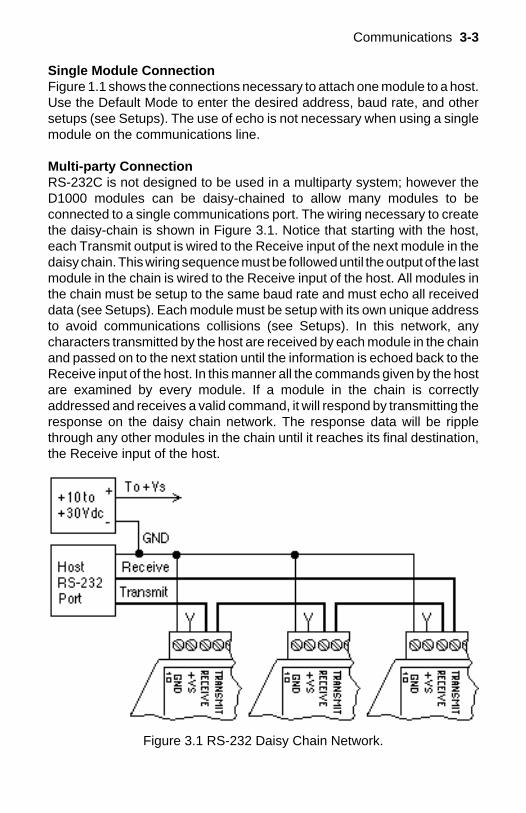
Communications 3-3
Single Module ConnectionFigure 1.1 shows the connections necessary to attach one module to a host.Use the Default Mode to enter the desired address, baud rate, and othersetups (see Setups). The use of echo is not necessary when using a singlemodule on the communications line.
Multi-party ConnectionRS-232C is not designed to be used in a multiparty system; however theD1000 modules can be daisy-chained to allow many modules to beconnected to a single communications port. The wiring necessary to createthe daisy-chain is shown in Figure 3.1. Notice that starting with the host,each Transmit output is wired to the Receive input of the next module in thedaisy chain. This wiring sequence must be followed until the output of the lastmodule in the chain is wired to the Receive input of the host. All modules inthe chain must be setup to the same baud rate and must echo all receiveddata (see Setups). Each module must be setup with its own unique addressto avoid communications collisions (see Setups). In this network, anycharacters transmitted by the host are received by each module in the chainand passed on to the next station until the information is echoed back to theReceive input of the host. In this manner all the commands given by the hostare examined by every module. If a module in the chain is correctlyaddressed and receives a valid command, it will respond by transmitting theresponse on the daisy chain network. The response data will be ripplethrough any other modules in the chain until it reaches its final destination,the Receive input of the host.
Figure 3.1 RS-232 Daisy Chain Network.
3-4 D1000 USERS MANUAL
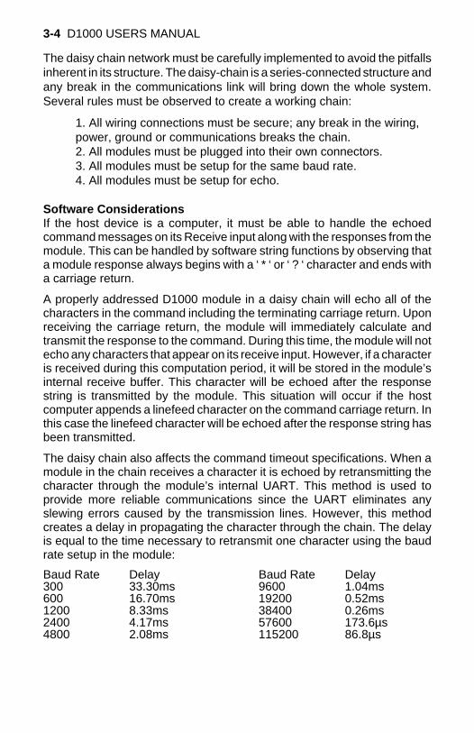
The daisy chain network must be carefully implemented to avoid the pitfallsinherent in its structure. The daisy-chain is a series-connected structure andany break in the communications link will bring down the whole system.Several rules must be observed to create a working chain:
1. All wiring connections must be secure; any break in the wiring,power, ground or communications breaks the chain.2. All modules must be plugged into their own connectors.3. All modules must be setup for the same baud rate.4. All modules must be setup for echo.
Software ConsiderationsIf the host device is a computer, it must be able to handle the echoedcommand messages on its Receive input along with the responses from themodule. This can be handled by software string functions by observing thata module response always begins with a ‘ * ‘ or ‘ ? ‘ character and ends witha carriage return.
A properly addressed D1000 module in a daisy chain will echo all of thecharacters in the command including the terminating carriage return. Uponreceiving the carriage return, the module will immediately calculate andtransmit the response to the command. During this time, the module will notecho any characters that appear on its receive input. However, if a characteris received during this computation period, it will be stored in the module’sinternal receive buffer. This character will be echoed after the responsestring is transmitted by the module. This situation will occur if the hostcomputer appends a linefeed character on the command carriage return. Inthis case the linefeed character will be echoed after the response string hasbeen transmitted.
The daisy chain also affects the command timeout specifications. When amodule in the chain receives a character it is echoed by retransmitting thecharacter through the module’s internal UART. This method is used toprovide more reliable communications since the UART eliminates anyslewing errors caused by the transmission lines. However, this methodcreates a delay in propagating the character through the chain. The delayis equal to the time necessary to retransmit one character using the baudrate setup in the module:
Baud Rate Delay Baud Rate Delay300 33.30ms 9600 1.04ms600 16.70ms 19200 0.52ms1200 8.33ms 38400 0.26ms2400 4.17ms 57600 173.6µs4800 2.08ms 115200 86.8µs
Communications 3-5
One delay time is accumulated for each module in the chain. For example,if four modules are used in a chain operating at 1200 baud, the accumulateddelay time is 4 X 8.33 mS = 33.3 mS This time must be added to the timeslisted in Table 3.1 to calculate the correct communications time-out error.
For modules with RS-232C outputs, the programmed communicationsdelay specified in the setup data (see Chapter 5) is implemented by sendinga NULL character (00) followed by an idle line condition for one charactertime. This results in a delay of two character periods. For longer delay timesspecified in the setup data, this sequence is repeated. Programmedcommunications delay is seldom necessary in an RS-232C daisy chainsince each module in the chain adds one character of communicationsdelay.
Changing Baud RateIt is possible to change the baud rate of an RS-232C daisy chain on-line. Thisprocess must be done carefully to avoid breaking the communications link.
1. Use the SetUp (SU) command to change the baud rate setup on eachmodule in the chain. Be careful not to generate a reset during this process.A reset can be caused by the Remote Reset (RR) command or powerinterruptions.
2. Verify that all the modules in the chain contain the new baud rate setupusing the Read Setup (RS) command. Every module in the chain must besetup for the same baud rate.
3. Remove power from all the modules for at least 10 seconds. Restorepower to the modules. This generates a power-up reset in each module andloads in the new baud rate.
4. Change the host baud rate to the new value and check communica-tions.
5. Be sure to compensate for a different communications delay as aresult of the new baud rate.
Using A Daisy-Chain With A Dumb TerminalA dumb terminal can be used to communicate to a daisy-chained system.The terminal is connected in the same manner as a computer used as a host.Any commands typed into the dumb terminal will be echoed by the daisychain. To avoid double characters when typing commands, set the terminalto full duplex mode or turn off the local echo. The daisy chain will provide theinput command echo.
3-6 D1000 USERS MANUAL
RS-485RS-485 is a recently developed communications standard to satisfy theneed for multidropped systems that can communicate at high data ratesover long distances. RS-485 is similar to RS-422 in that it uses a balanceddifferential pair of wires switching from 0 to 5V to communicate data. RS-485receivers can handle common mode voltages from -7V to +12V without lossof data, making them ideal for transmission over great distances. RS-485differs from RS-422 by using one balanced pair of wires for both transmittingand receiving. Since an RS-485 system cannot transmit and receive at thesame time it is inherently a half-duplex system. RS-485 offers manyadvantages over RS-232C:
1) balanced line gives excellent noise immunity2) can communicate with D1000 modules at 115200 baud3) communications distances up to 4,000 feet.4) true multidrop; modules are connected in parallel5) can disconnect modules without losing communications6) up to 32 modules on one line; 122 with repeaters7) no communications delay due to multiple modules8) simplified wiring using standard telephone cable
RS-485 does have disadvantages. Very few computers or terminals havebuilt-in support for this new standard. Interface boards are available for theIBM PC and compatibles and other RS-485 equipment will become avail-able as the standard gains popularity. An RS-485 system usually requiresan interface.
We offer the A1000 and A2000 interface converters that will convert RS-232signals to RS-485 or repeat RS-485 signals. The A1000 converters alsoinclude a +24Vdc, one amp power supply for powering D1000 seriesmodules. The A1000 or A2000 connected as an RS-485 repeater can beused to extend an existing RS-485 network or connect up to 122 moduleson one serial communications port.
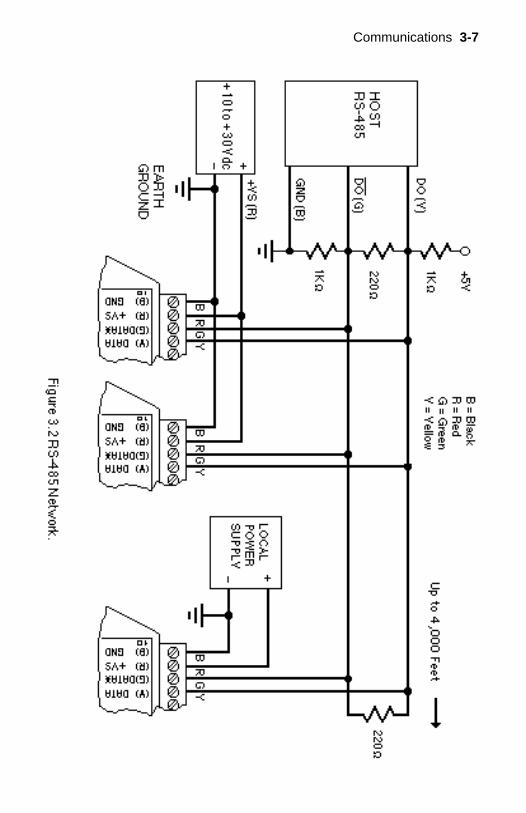
Communications 3-7
3-8 D1000 USERS MANUAL
RS-485 Multidrop SystemFigure 3.2 illustrates the wiring required for multiple-module RS-485 sys-tem. Notice that every module has a direct connection to the host system.Any number of modules may be unplugged without affecting the remainingmodules. Each module must be setup with a unique address and theaddresses can be in any order. All RS-485 modules must be setup for noecho to avoid bus conflicts (see Setup). Also note that the connector pins oneach module are labelled with notations (B), (R), (G), and (Y). Thisdesignates the colors used on standard 4-wire telephone cable:
Label Color
(B) GND Black(R) V+ Red(G) DATA* (-) Green(Y) DATA (+) Yellow
This color convention is used to simplify installation. If standard 4-wiretelephone cable is used, it is only necessary to match the labeled pins withthe wire color to guarantee correct installation.
DATA* on the label is the complement of DATA (negative true).
To minimize unwanted reflections on the transmission line, the bus shouldbe arranged as a line going from one module to the next. ‘Tree’ or randomstructures of the transmission line should be avoided. When using longtransmission lines and/or high baud rates, the data lines should be termi-nated at each end with 200 ohm resistors. Standard values of 180 ohms or220 ohms are acceptable.
During normal operation, there are periods of time where all RS-485 driversare off and the communications lines are in an 'idle' high impedancecondition. During this condition, the lines are susceptible to noise pickupwhich may be interpreted as random characters on the communicationsline. To prevent noise pickup, all RS-485 systems should incorporate 1Kohm bias resistors as shown in Figure 3.2. The resistors will maintain thedata lines in a 'mark' condition when all drivers are off.
A1000 series converter boxes have the 1KΩ resistors built-in. The resistorsare user-selectable via dip switch located on the rear panel of the A1000.
Special care must be taken with very long busses (greater than 1000 feet)to ensure error-free operation. Long busses must be terminated as de-scribed above. The use of twisted cable for the DATA and DATA* lines willgreatly enhance signal fidelity. Use parity and checksums along with the ‘#’form of all commands to detect transmission errors. In situations wheremany modules are used on a long line, voltage drops in the power leads
Communications 3-9
becomes an important consideration. The GND wire is used both as a powerconnection and the common reference for the transmission line receivers inthe modules. Voltage drops in the GND leads appear as a common-modevoltage to the receivers. The receivers are rated for a maximum of -7V. ofcommon-mode voltage. For reliable operation, the common mode voltageshould be kept below -5V.
To avoid problems with voltage drops, modules may be powered locallyrather than transmitting the power from the host. Inexpensive 'calculator'type power supplies are useful in remote locations. When local supplies areused, be sure to provide a ground reference with a third wire to the host orthrough a good earth ground. With local supplies and an earth ground, onlytwo wires for the data connections are necessary.
Communications Delay
All D1000 modules with RS-485 outputs are setup at the factory to providetwo units of communications delay after a command has been received (seeChapter 5). This delay is necessary when using host computers that transmita carriage return as a carriage return-linefeed string. Without the delay, thelinefeed character may collide with the first transmitted character from themodule, resulting in garbled data. If the host computer transmits a carriagereturn as a single character, the delay may be set to zero to improvecommunications response time.

3-10 D1000 USERS MANUAL

The D1000 modules operate with a simple command/response protocol tocontrol all module functions. A command must be transmitted to the moduleby the host computer or terminal before the module will respond with usefuldata. A module can never initiate a communications sequence. A variety ofcommands exists to exploit the full functionality of the modules. A list ofavailable commands and a sample format for each command is listed inTable 4.1.
Command StructureEach command message from the host must begin with a command promptcharacter to signal to the modules that a command message is to follow.There are four valid prompt characters; a dollar sign character ($) is used togenerate a short response message from the module. A short response isthe minimum amount of data necessary to complete the command. Thesecond prompt character is the pound sign character (#) which generateslong responses (will be covered later in this chapter). The other two promptcharacters: left curly brace ( ) and right curly brace ( ) are part of theExtended Addressing mode described in chapter 10
The prompt character must be followed by a single address characteridentifying the module to which the command is directed. Each moduleattached to a common communications port must be setup with its ownunique address so that commands may be directed to the proper unit.Module addresses are assigned by the user with the SetUp (SU) command.Printable ASCII characters such as ‘1’ (ASCII $31) or ‘A’ (ASCII $41) are thebest choices for address characters.
The address character is followed by a two-character command thatidentifies the function to be performed by the module. All of the availablecommands are listed in Table 4.1 along with a short function definition. Allcommands are described in Chapter 4. Commands must be transmitted asupper-case characters.
A two-character checksum may be appended to any command message asa user option. See ‘Checksum’ in Chapter 4 .
All commands must be terminated by a Carriage Return character (ASCII$0D). (In all command examples in this text the Carriage Return is eitherimplied or denoted by the symbol ‘CR’.)
In addition to the command structure discussed above there is a specialcommand format called Extended Addressing. This mode uses a differ-ent prompt, either '' or '' to distinguish it from the regular commandsyntax. The Extended Addressing mode is described in chapter 10.
Chapter 4Command Set
4-2 D1000 USERS MANUAL
Data StructureMany commands require additional data values to complete the commanddefinition as shown in the example commands in Table 4.1. The particulardata necessary for these commands is described in full in the completecommand descriptions.
The most common type of data used in commands and responses is analogdata. Analog data is always represented in the same format for all modelsin the D1000 series. Analog data is represented as a nine-character stringconsisting of a sign, five digits, decimal point, and two additional digits. Thestring represents a decimal value in engineering units. Examples:
+12345.68+00100.00-00072.10-00000.00
When using commands that require analog data as an argument, the fullnine-character string must be used, even if some digits are not significant.Failure to do this results in a SYNTAX ERROR.
Analog data responses from the module will always be transmitted in thenine-character format. This greatly simplifies software parsing routinessince all analog data is in the same format for all module types.
In many cases, some of the digits in the analog data may not be significant.For instance, the D1300 thermocouple input modules feature 1 degreeoutput resolution. A typical analog data value from this type of module couldbe +00123.00. The two digits to the right of the decimal point have nosignificance in this particular model. However, the data format is alwaysadhered to in order to maintain compatibility with other module types.
The maximum computational resolution of the module is 16 bits, which isless than the resolution that may be represented by an analog data variable.This may lead to round-off errors in some cases. For example, an alarmvalue may be stored in a D1000 module using the ‘HI’ command:
Command: $1HI+12345.67MResponse: *
The alarm value is read back with the Read High (RH) command:
Command: $1RHResponse: *+12345.60M
It appears that the data read back does not match the value that wasoriginally saved. The error is caused by the fact that the value saved exceedsthe computational resolution of the module. This type of round-off error only
Command Set 4-3
appears when large data values saved in the module’s EEPROM are readback. In most practical applications, the problem is non-existent.
Overload values of analog data are +99999.99 and -99999.99 .
Data read back from the Event Counter with the Read Events (RE)command is in the form of a seven-digit decimal number with no sign ordecimal point. Round-off errors do not occur on the event counter. Forexample:
Command: $1REResponse: *0000123
The Digital Input, Digital Output, and Setup commands use hexadecimalrepresentations of data. The data structures for these commands aredetailed in the command descriptions.
Write ProtectionMany of the commands listed in Table 4.1 are under the heading of ‘WriteProtected Commands’. These commands are used to alter setup data in themodule’s EEPROM. They are write protected to guard against accidentalloss of setup data. All write-protected commands must be preceded by aWrite Enable (WE) command before the protected command may beexecuted.
Miscellaneous Protocol NotesThe address character must transmitted immediately after the commandprompt character. After the address character the module will ignore anycharacter below ASCII $23 (except CR). This allows the use of spaces(ASCII $20) within the command message for better readability if desired.
The length of a command message is limited to 20 printable characters. Ifa properly addressed module receives a command message of more than20 characters the module will abort the whole command sequence and noresponse will result.
If a properly addressed module receives a second command prompt beforeit receives a CR, the command will be aborted and no response will result.
Response StructureResponse messages from the module begin with either an asterisk ‘ * ‘(ASCII $2A) or a question mark ‘ ? ‘ (ASCII $3F) prompt. The ‘ * ‘ promptindicates acknowledgment of a valid command. The ‘ ? ‘ prompt precedesan error message. All response messages are terminated with a CR. Manycommands simply return a ‘ * ‘ character to acknowledge that the commandhas been executed by the module. Other commands send data information
4-4 D1000 USERS MANUAL
following the ‘ * ‘ prompt. The response format of all commands may be foundin the detailed command description.
The maximum response message length is 20 characters.
A command/response sequence is not complete until a valid response isreceived. The host may not initiate a new command until the response froma previous command is complete. Failure to observe this rule will result incommunications collisions. A valid response can be in one of three forms:
1) a normal response indicated by a ‘ * ‘ prompt2) an error message indicated by a ‘ ? ‘ prompt3) a communications time-out error
When a module receives a valid command, it must interpret the command,perform the desired function, and the communicate the response back to thehost. Each command has an associated delay time in which the module isbusy calculating the response. If the host does not receive a response in anappropriate amount of time specified in Table 4.1, a communications time-out error has occurred. After the communications time-out it is assumed thatno response data is forthcoming. This error usually results when animproper command prompt or address is transmitted.
Long Form ResponsesWhen the pound sign ‘ # ‘ command prompt is used, the module respondswith a ‘long form’ response. This type of response will echo the commandmessage, supply the necessary response data and will add a two-characterchecksum to the end of the message. Long form responses are used whenthe host wishes to verify the command received by the module. Thechecksum is included to verify the integrity of the response data. The ‘ # ‘command prompt may be used with any command. For example:
Command: $1RD (short form)Response: *+00072.10
Command: #1RD (long form)Response: *1RD+00072.10A4 (A4=checksum)
ChecksumChecksum is a two character hexadecimal value appended to the end of amessage. It verifies that the message received is exactly the same as themessage sent. The checksum ensures the integrity of the informationcommunicated.
Command ChecksumA two-character checksum may be appended to any command to themodule as a user option. When a module interprets a command, it looks for
Command Set 4-5
the two extra characters and assumes that it is a checksum. If the checksumis not present, the module will perform the command normally. If the twoextra characters are present, the module calculates the checksum for themessage. If the calculated checksum does not agree with the transmittedchecksum, the module responds with a ‘BAD CHECKSUM’ error messageand the command is aborted. If the checksums agree, the command isexecuted. If the module receives a single extra character, it responds with‘SYNTAX ERROR’ and the command is aborted For example:
Command: $1RD (no checksum)Response: *+00072.10
Command: $1RDEB (with checksum)Response: *+00072.10
Command: $1RDAB (incorrect checksum)Response: ?1 BAD CHECKSUM
Command: $1RDE (one extra character)Response: ?1 SYNTAX ERROR
Response ChecksumsIf the long form ‘ # ‘ version of a command is transmitted to a module, achecksum will be appended to the end of the response. For example:
Command: $1RD (short form)Response: *+00072.10
Command: #1RD (long form)Response: *1RD+00072.10A4 (A4=checksum)
Checksum Calculatio nThe checksum is calculated by summing the hexadecimal values of all theASCII characters in the message. The lowest order two hex digits of the sumare used as the checksum. These two digits are then converted to theirASCII character equivalents and appended to the message. This ensuresthat the checksum is in the form of printable characters.
Example: Append a checksum to the command #1DOFF
Characters: # 1 D O F FASCII hex values: 23 31 44 4F 46 46Sum (hex addition) 23 + 31 + 44 + 4F + 46 + 46 = 173
The checksum is 73 (hex). Append the characters 7 and 3 to the end ofthe message: #1DOFF73
Example: Verify the checksum of a module response *1RD+00072.10A4
4-6 D1000 USERS MANUAL
The checksum is the two characters preceding the CR: A4
Add the remaining character values:
* 1 R D + 0 0 0 7 2 . 1 02A + 31 + 52 + 44 + 2B + 30 + 30 + 30 + 37 + 32 + 2E + 31 + 30 = A4
The two lowest-order hex digits of the sum are A4 which agrees with thetransmitted checksum.
The transmitted checksum is the character string equivalent to the calcu-lated hex integer. The variables must be converted to like types in the hostsoftware to determine equivalency.
If checksums do not agree, a communications error has occurred.
If a module is setup to provide linefeeds, the linefeed characters are notincluded in the checksum calculation.
Parity bits are never included in the checksum calculation.
Table 4.1 D1000 Command SetCommand and Definition Typical Typical
Command ResponseMessage Message
($ prompt)
DI Read Alarms/Digital Inputs $1DI *0003DO Set Digital Outputs $1DOFF *ND New Data $1ND *+00072.00RD Read Data $1RD *+00072.00RE Read Event Counter $1RE *0000107REA Read Extended Address $1REA *3031RH Read High Alarm Value $1RH *+00510.00LRID Read IDentification $1RID * BOILERRL Read Low Alarm Value $1RL *+00000.00LRPT Read Pulse Transition $1RPT *+-RS Read Setup $1RS *31070142RZ Read Zero $1RZ *+00000.00WE Write Enable $1WE *
Write Protected Commands
CA Clear Alarms $1CA *CE Clear Events $1CE *CZ Clear Zero $1CZ *DA Disable Alarms $1DA *EA Enable Alarms $1EA *
Command Set 4-7
EC Events Read & Clear $1EC *0000107HI Set High Alarm Limit $1HI+12345.67L *ID IDentification $1ID BOILER *LO Set Low Alarm Limit $1LO+12345.67L *PT Pulse Transition $1PT+- *RR Remote Reset $1RR *SU Setup Module $1SU31070142 *SP Set Setpoint $1SP+00600.00 *TS Trim Span $1TS+00600.00 *TZ Trim Zero $1TZ+00000.00 *WEA Write Extended Address $1WEA3031 *
D1000 User CommandsNote that in all command and response examples given below, a carriagereturn is implied after every character string.
Clear Alarms (CA )The clear alarms command turns both the HI and LO alarms OFF. Thiscommand does not affect the enable/disable or momentary/latching alarmconditions. The alarms will continue to be compared to the input data afterthe CA command is given. In cases where the alarm condition persists, thealarms will be set at the end of the next input data conversion. The primarypurpose of the CA command is to clear latching alarms. See the AlarmOutput section of Chapter 6 for more information.
Command: $1CAResponse: *
Command: #1CAResponse: *1CADF
Clear Events (CE)Clear Events command clears the events counter to 0000000.
Command: $1CEResponse: *
Command: #1Response: *1CEE3
Note: When the events counter reaches 9999999, it stops counting. A CEcommand must be sent to resume counting.
Clear Zero (CZ)The Clear Zero command clears the output offset register value to+00000.00. This command clears any data resulting from a Trim Zero (TZ)
4-8 D1000 USERS MANUALor SetPoint (SP) command.
Command: $1CZResponse: *
Command: #1CZResponse: *1CZF8
Disable Alarms (DA)Most D1000 modules feature LO/DO0 and HI/DO1 pins on the moduleconnector. These pins serve a dual function and can be used to output eitherthe alarm outputs or digital outputs 0 and 1. The Disable Alarms commandis used to connect the digital outputs 0 and 1 to the connector pins. The alarmsettings are not affected in any way except that the alarm outputs aredisconnected from the module connector. The alarm status can still be readwith the Digital Input (DI) command. The complement to the DA commandis the Enable Alarms (EA) command.
Command: $1DAResponse: *
Command: #1DAResponse: *1DAE0
Digital Input (DI)The DI command reads the status of the digital inputs and the alarms. Theresponse to the DI command is four hex characters representing two bytesof data. The first byte contains the alarm status. The second byte containsthe digital input data.
Command: $1DIResponse: *0003
Command: #1DIResponse: *1DI0003AB
Listed below are the four possible alarm states in the first digital input byteand their hex values.
00 Both HI and LO alarms off.01 HI alarm off. LO alarm on.02 HI alarm on. LO alarm off.03 Both HI and LO alarms on.
The second byte displays the hex value of the digital input status. Thenumber of digital inputs varies depending on module type.
Digital Inputs DI7 DI6 DI5 DI4 DI3 DI2 DI1 DI0Data Bits 7 6 5 4 3 2 1 0
Command Set 4-9
For example: A typical response from a $1DI command could be: *01FE.This response indicates that the HI alarm is off, the LO alarm is on, DI0 = 0and all other digital inputs are = 1
All digital inputs that are not implemented or left unconnected are read as‘1’
Digital input 0 serves a dual function. It is both a digital input and the EventCounter input.
When reading digital inputs with a checksum, be sure not to confuse thechecksum with the data.
Digital Output (DO )The DO command controls eight bits of digital outputs on the moduleconnector. The number of digital outputs implemented depends on themodel used. The digital outputs allow the module to control external circuitsunder host command. The DO command requires an argument of two hexcharacters specifying the eight bits of output data.
Digital Outputs DO7 DO6 DO5 DO4 DO3 DO2 DO1 DO0Data Bits 7 6 5 4 3 2 1 0
The electrical implementation of the digital output consists of open-collectortransistors wired to the module connector. If a digital output is set to ‘1’ thecorresponding transistor is turned on and sinks current. Note that when adigital output bit is set to ‘1’ the electrical output is near 0 volts. If a digitaloutput is set to ‘0’ the corresponding transistor is turned off and sinks nocurrent.
Assume a module has two digital outputs, and you wish to turn both outputson (sinking current). Set data bit 0 and data bit 1 to ‘1’. Since the module hasonly two digital outputs, all the other bits are ‘don’t cares’. For example, thiscommand will turn both outputs ‘on’:
Command: $1DOFFResponse: *
To turn both outputs off you could use the command:
Command: $1DO00Response: *
Digital outputs 0 and 1 share connector pins with the HI and LO alarms. TheDisable Alarms (DA) command is used to configure these pins as digitaloutputs.
Digital output settings are not stored in nonvolatile memory. If a power failureoccurs, all digital outputs will be 0 upon power up.

4-10 D1000 USERS MANUAL
Command Set 4-11
The alarm limit should be set within the output range of the module. If thealarm limit is set beyond the output range, the alarm will be activated onlyon an overload condition.
The high alarm value may be read back with the Read High Alarm (RH)command.
A latched alarm may be cleared with the Clear Alarms (CA) command. Moreinformation on alarms may be found in Chapter 6.
IDentification (ID)The IDentification command allows the user to write a message into theinternal nonvolatile memory which may be read back at any time using theRead IDentification (RID) command. The message may be up to 16characters long and has no affect on the module operation. Useful informa-tion such as the module location, calibration date or model number may bestored for later retrieval.
The ID command is write protected and checksums are not supported. Themodule will abandon any ID command with a message length in excess of16 characters.
Command: $1IDBOILER ROOMResponse: *
Command: #1IDBOILER ROOMResponse: *1IDBOILER ROOM02
Low Alarm Limit (LO)The low alarm command sets the value and type of the low alarm. The dataspecified with the LO command is stored in nonvolatile memory andcompared with the sensor data after every A/D conversion. If the input datais less than the low limit, the low alarm is activated. The low alarm status maybe read using the Digital Input (DI) command. The alarm may be used toactivate a digital output by using the Enable Alarms (EA) command. A letterindicating the alarm type, “L” for latching or “M” for momentary, must followthe alarm value. For example:
Command: $1LO+00000.00MResponse: *
Command: #1LO+00000.00MResponse: *1LO+00000.00MEC
The alarm limit should be set within the output range of the module. If thealarm limit is set beyond the output range, the alarm will be activated onlyon an overload condition.
4-12 D1000 USERS MANUAL
The low limit value may be read back with the Read Low Limit (RL)command. More information on alarms may be found in Chapter 6.
New Data Command (ND)The New Data (ND) command is a variation of the Read Data (RD)command used to read sensor data from the module. The ND commandguarantees that the output data has not been previously read.
The D1000 module acquires analog input data eight times a second andstores the result in the output buffer (see Figure 2.1). The Read Data (RD)command simply reads the results stored in the output buffer. A fast hostcommunicating at a high baud rate could possibly read the output bufferseveral times before the information is updated with a new A/D conversion.This results in redundant information which may be confusing or may be awaste of host processor time.
Associated with the output buffer is the New Data Flag (see Figure 2.1). Thisflag is cleared each time an RD or ND command is performed. The flag isset when the module’s microprocessor loads the output buffer with the resultof the most recent A/D conversion. The ND command will output data onlywhen the New Data Flag is set. If the flag is cleared when an ND commandis received, the module will wait until new data is present in the output bufferbefore responding to the command. Thus, the output data obtained with anND command is always the result of a new A/D conversion.
The ND command is especially useful with computers that handle commu-nications on an interrupt basis. The ND command is used to get maximumthroughput without producing redundant data.
Command: $1NDResponse: *+00072.00
Command: #1NDResponse: *1ND+00072.009F
A special condition exists when using the ND command with the D1600frequency/pulse modules. These modules differ from the other sensor inputmodules in that they require an input trigger signal to obtain new data. If nosignal exists on the input of the D1600, an ND command will wait indefinitelyfor new data and the module will not respond.
In order to escape this condition, a single control-C ($03) may be issued bythe host to abort the ND command. The aborted ND command will respondwith the data value currently stored in the output buffer. Be aware that on anRS-485 system, the control-C character may interfere with the ND outputdata, causing a communications collision.
Command Set 4-13
Pulse Transition (PT)The Pulse Transition command is used on Frequency and Timer inputmodules. It is used to set the direction of the edge used to trigger themeasurement cycle. There are four possible edge transitions: (+ to -), (- to+), (- to -), (+ to +). For example:
Command: $1PT+ -Response: *
Command: #1PT
Response: *1PT+ -50
Read Data (RD)The read data command is the basic command used to read the bufferedsensor data. The output buffer (Figure 2.1) allows the data to be readimmediately without waiting for an input A/D conversion. For example:
Command: $1RDResponse: *+00072.00
Command: #1RDResponse: *1RD+00072.10A4
Since the RD command is the most frequently used command in normaloperation, a special shortened version of the command is available. If amodule is addressed without a two-letter command, the module interpretsthe string as an RD command.
Command: $1Response: *+00072.10
Command: #1Response: *1RD+00072.10A4
Read Events (RE)The Read Events command reads the number of events that have beenaccumulated in the Events Counter. The output is a seven-digit decimalnumber. For example:
Command: $1REResponse: *0000107
Command: #1REResponse: *1RE00001074A
The maximum accumulated count is 9999999. When this count is reached,the Events Counter stops counting. The counter may be cleared at any timewith the Clear Events (CE) command.
The Event Counter count is stored in volatile memory. If power is removed,the Event Counter will reset to all 0’s upon power up.
4-14 D1000 USERS MANUAL
The Remote Reset (RR) command or a line break does not effect the valueof the Event Counter.
When reading the Event Counter with a checksum, be sure not to confusethe checksum with the data.
Read Extended Address (REA)The Read Extended Address is used to read back two character addressstored by the Extended Address (EA) command. The response message isfour characters representing the hex ASCII codes for the two-characteraddress :
Command: $1REAResponse: *3031
Command: #1REAResponse: *1REA3031FA
In this example the '30' and '31' are the hex ASCII codes for the characters'0' and '1' respectively. The Extended Address is '01'.
Read High Alarm (RH)The Read High alarm command reads the value and type of the high alarmpreviously loaded by the HI command. The alarm type can be either latchingor momentary. A letter indicating the alarm type, “L” for latching or “M” formomentary, will follow the alarm value. For example:
Command: $1RHResponse: *+00510.00L
Command: #1RHResponse: *1RH+00510.00LF0
The RH command may be used to verify the data loaded into nonvolatilememory by the HI command.
Read IDentification (RID)The Read Identification (RID) command is used to read data previouslystored by the ID command. The RID command response message lengthis variable depending on the stored message length. The maximum re-sponse length can be up to 25 characters using the long form prompt andlinefeeds enabled.
Command: $1RIDResponse: *BOILER ROOM
Command: #1RIDResponse: *1RIDBOILER ROOM54

Command Set 4-15
Read Low Alarm (RL)The Read Low alarm command reads the value and type of the low alarm.The alarm type can be either latching or momentary. A letter indicating thealarm type, “L” for latching or “M” for momentary, will follow the alarm value.For example:
Command: $1RLResponse: *+00000.00LCommand: #1RL
Response: *1RL+00000.00LEE
The RL command may be used to verify data loaded into the nonvolatilememory with the LO command.
Read Pulse Transition (RPT)The Read Pulse Transition command is used on the Timer and Frequencyinput modules. The RPT command reads the direction of the edge used totrigger the measurement cycle. The direction of the pulse transition is set bythe user using the Pulse Transition (PT) command. There are four possibleedge transitions: (+ to -), (- to +), (- to -), (+ to +). For example:
Command: $1RPTResponse: *+ -Command: #1RPT
Response: *1RPT+ -A2
Remote Reset (RR)The reset command allows the host to perform a program reset on themodule’s microprocessor. This may be necessary if the module’s internalprogram is disrupted by static or other electrical disturbances. Once a resetcommand is received, the module will recalibrate itself. The calibrationprocess takes approximately 3 seconds. For example:
Command: $1RRResponse: *
Command: #1RRResponse: *1RRFF
In general, the state of the digital outputs and the event counter will not beaffected by the RR command. However, if data in the microprocessor’s RAM(Random Access Memory) has been lost, the RR command will result in afull power-up reset.
Any commands sent to the module during the self-calibration sequence willresult in a NOT READY error.
4-16 D1000 USERS MANUAL
Read Setup (RS)The read setup command reads back the setup information loaded into themodule’s nonvolatile memory with the SetUp (SU) command. The responseto the RS command is four bytes of information formatted as eight hexcharacters.
Command: $1RSResponse: *31070142
Command: #1RSResponse: *1RS3107014292
The response contains the module’s channel address, baud rate and otherparameters. Refer to the setup command (SU), and Chapter 5 for a list ofparameters in the setup information.
When reading the setup with a checksum, be sure not to confuse thechecksum with the setup information.
Read Zero (RZ)The Read Zero command reads back the value stored in the Output OffsetRegister (Figure 2.1).
Command: $1RZResponse: *+00000.00
Command: #1RZResponse: *1RZ+00000.00B0
The data read back from the Output Offset Register may be interpreted inseveral ways. The commands that affect this value are: Trim Zero (TZ),SetPoint (SP) and Clear Zero (CZ).
Setpoint (SP)Data specified by the setpoint command is multiplied by -1 and loaded intothe Output Offset Register (Figure 2.1). The SP command is useful in on-offcontrollers—see Chapter 6. The SP command may be used to null outsensor data to obtain a deviation output when using RD or ND commands.
Command: $1SP+00450.00Response: *
Command: #1SP+00450.00Response: *1SP+00450.00B0
It is possible to load setpoint data that is beyond the output range of thesensor. In this case, the setpoint is never reached by the sensor data unlessan overload is present.
Command Set 4-17
To clear a setpoint, use the Clear Zero (CZ) command.
The SP command writes over data written into the Output Offset Register bythe Trim Zero (TZ) command. If the Output Offset Register is used as a trimvalue, this must be accounted for by the host before using the SP command.The value stored in this register may be read back using the Read Zero (RZ)command.
The setpoint data or trim data in the Output Offset Register is saved innonvolatile memory.
Setup Command (SU)Each D1000 module contains an EEPROM (Electrically Erasable Program-mable Read Only Memory) which is used to store module setup informationsuch as address, baud rate, parity, etc. The EEPROM is a special type ofmemory that will retain information even if power is removed from themodule. The EEPROM is used to replace the usual array of DIP switchesnormally used to configure electronic equipment.
The SetUp command is used to modify the user-specified parameterscontained in the EEPROM to tailor the module to your application. Since theSetUp command is so important to the proper operation of a module, a wholesection of this manual has been devoted to its description. See Chapter 5.
The SU command requires an argument of eight hexadecimal digits todescribe four bytes of setup information:
Command: $1SU31070182Response: *
Command: #1SU31070182Response: *1SU3107018299
Trim Span (TS)The trim span command is the basic means of trimming the accuracy of aD1000 module. The TS command loads a calibration factor into nonvolatilememory to trim the full-scale output of the signal conditioning circuitry. It isintended only to compensate for long-term drifts due to aging of the analogcircuits, and has a useful trim value of ±10% of the nominal calibration setat the factory. It is not to be used to change the basic transfer function of themodule. Full information on the use of the TS command may be found inChapter 9.
Command: $1TS+00500.00Response: *
Command: #1TS+00500.00Response: *1TS+00500.00B0
4-18 D1000 USERS MANUAL
Caution! TS is the only command associated with the span trim. There is noprovision to read back or clear errors loaded by the TS command. Misuseof the TS command may destroy the calibration of the unit which can onlybe restored by using laboratory calibration instruments in a controlledenvironment. An input signal must be applied when using this command.
Trim Zero (TZ)The Trim Zero command is used to load a value into the Output OffsetRegister (Figure 2.1) to null out an offset in the output data. It may be usedto trim offsets created by sensors. It may also be used to null out data tocreate a deviation output.
Example: Assume a D1511 bridge input module is being used with a loadcell for weight measurement. An initial reading of the load cell with no weightapplied may reveal an initial offset error:
Command: $1RDResponse: *+00005.00
With no weight applied, trim the output to read zero. To trim, use the TZcommand and specify the desired output reading:
Command: $1TZ+00000.00 (zero output)Response: *
The TZ command will load a data value into the Output Offset Register toforce the output to read zero. The module will compensate for any previousvalue loaded into the Output Offset Register. If another output reading istaken, it will show that the offset has been eliminated:
Command: $1RDResponse: *+00000.00
Although the TZ command is most commonly used to null an output to zero,it may be used to offset the output to any specified value. Assume that withthe previously nulled load cell system we performed this command:
Command: $1TZ-00100.00Response: *
The new data output with no load applied would be:
Command: $1RDResponse: *-00100.00
The load cell output is now offset by -100.
The offset value stored by the TZ command is stored in nonvolatile memoryand may be read back with the Read Zero (RZ) command and cleared withthe Clear Zero (CZ) command.
Command Set 4-19
The SetPoint (SP) command will write over any value loaded by the TZcommand.
Write Enable (WE)Each module is write protected against accidental changing of alarms,limits, setup, or span and zero trims. To change any of these write protectedparameters, the WE command must precede the write-protected command.The response to the WE command is an asterisk indicating that the moduleis ready to accept a write-protected command. After the write-protectedcommand is successfully completed, the module becomes automaticallywrite disabled. Each write-protected command must be preceded individu-ally with a WE command. For example:
Command: $1WEResponse: *
Command: #1WEResponse: *1WEF7
If a module is write enabled and the execution of a command results in anerror message other than WRITE PROTECTED, the module will remainwrite enabled until a command is successfully completed resulting in an ‘ *‘ prompt. This allows the user to correct the command error without havingto execute another WE command.
Write Extended Address (WEA)The Write Extended Address (WEA) command allows the user to set thetwo-byte address to be used with Extended Addressing (see Chapter 7). Theargument of the command specifies the hex ASCII values of the twocharacters to be used as the Extended Address. For example, if the addressis to be set for characters '01':
Command: $1WEA3031Response: *
Command: #1WEA3031Response: *1WEA3031FF
Note that '30' and '31' are the hex ASCII values for characters '0' and '1'respectively.
The EA command is write-protected and must be preceded with a WEcommand.
The address data may be read back with the Read Extended Address (REA)command.
4-20 D1000 USERS MANUAL
ERROR MESSAGESThe D1000 modules feature extensive error checking on input commandsto avoid erroneous operation. Any errors detected will result in an errormessage and the command will be aborted.
All error messages begin with “?” , followed by the channel address, a spaceand error description. The error messages have the same format for eitherthe ‘ $ ‘ or ‘ # ‘ prompts. For example:
?1 SYNTAX ERROR
There are eight error messages, and each error message begins with adifferent character. It is easy for a computer program to identify the errorwithout having to read the entire string.
ADDRESS ERRORThere are six ASCII values that are illegal for use as a module address:NULL ($00), CR ($0D), $ ($24), # ($23), ($7B) and ($7D). The ADDRESSERROR will occur when an attempt is made to load an illegal address intoa module with the SetUp (SU) command. An attempt to load an addressgreater than $7F will produce an error.
BAD CHECKSUMThis error is caused by an incorrect checksum included in the commandstring. The module recognizes any two hex characters appended to acommand string as a checksum. Usually a BAD CHECKSUM error is due tonoise or interference on the communications line. Often, repeating thecommand solves the problem. If the error persists, either the checksum iscalculated incorrectly or there is a problem with the communicationschannel. More reliable transmissions might be obtained by using a lowerbaud rate.
COMMAND ERRORThis error occurs when the two-character command is not recognized by themodule. Often this error results when the command is sent with lower-caseletters. All valid commands are upper-case.
NOT READYIf a module is reset, it performs a self-calibration routine which takes 2-3seconds to complete. Any commands sent to the module during the self-calibration period will result in a NOT READY error. When this occurs, simplywait a couple seconds and repeat the command.
The module may be reset in three ways: a power-up reset, a Remote Reset(RR) command, or an internal reset. All modules contain a ‘watchdog’ timer
Command Set 4-21
to ensure proper operation of the microprocessor. The timer may be trippedif the microprocessor is executing its program improperly due to powertransients or static discharge.
If the NOT READY error persists for more than 30 seconds, check the powersupply to be sure it is within specifications.
PARITY ERRORA parity error can only occur if the module is setup with parity on (see Setup).Usually a parity error results from a bit error caused by interference on thecommunications line. Random parity errors are usually overcome by simplyrepeating the command. If too many errors occur, the communicationschannel may have to be improved or a slower baud rate may be used.
A consistent parity error will result if the host parity does not match themodule parity. In this situation, the easiest solution may be to change theparity in the host to obtain communication. At this point the parity in themodule may be changed to the desired value with the SetUp (SU) command.
The parity may be changed or turned off by using Default Mode.
SYNTAX ERRORA SYNTAX ERROR will result if the structure of the command is not correct.This is caused by having too few or too many characters, signs or decimalpoints missing or in the wrong place. Table 4.1 lists the correct syntax for allthe commands.
VALUE ERRORThis error results when an incorrect character is used as a numerical value.Data values can only contain decimal digits 0-9. Hex values used in theSetUp (SU) and Digital Output (DO) commands can range from 0-F.
WRITE PROTECTEDAll commands that write data into nonvolatile memory are write-protected toprevent accidental erasures. These commands must be preceded with aWrite Enable (WE) command or else a WRITE PROTECTED error willresult.

4-22 D1000 USERS MANUAL
The D1000 modules feature a wide choice of user configurable optionswhich gives them the flexibility to operate on virtually any computer orterminal based system. The user options include a choice of baud rate,parity, address, and many other parameters. The particular choice ofoptions for a module is referred to as the setup information.
The setup information is loaded into the module using the SetUp (SU)command. The SU command stores 4 bytes (32 bits) of setup informationinto a nonvolatile memory contained in the module. Once the information isstored, the module can be powered down indefinitely (10 years minimum)without losing the setup data. The nonvolatile memory is implemented withEEPROM so there are no batteries to replace.
The EEPROM has many advantages over DIP switches or jumpers normallyused for option selection. The module never has to be opened because allof the options are selected through the communications port. This allows thesetup to be changed at any time even though the module may be locatedthousands of feet away from the host computer or terminal. The setupinformation stored in a module may be read back at any time using the ReadSetup command (RS).
The following options can be specified by the SetUp command:
Channel address (122 values)LinefeedsParity (odd, even, none)Baud rate (300 to 115,200)Addressing Mode: Extended/NormalAlarm enable/disableAlarm momentary / latchingCJC disable (D1300 series)RTD 3/4 wire (D1400 series)Fahrenheit / CelsiusEchoCommunication delay (0-6 characters)Number of displayed digitsLarge-signal filter constantSmall-signal filter constant
Each of these options will be described in detail below. For a quick look-upchart on all options, refer to Tables 5.1-4.
Chapter 5Setup Information/SetUp Command
5-2 D1000 USERS MANUAL
Command SyntaxThe general format for the SetUp (SU) command is:
$1SU[byte1][byte 2][byte 3][byte 4]
A typical SetUp command would look like: $1SU31070182.
Notice that each byte is represented by its two-character ASCII equivalent.In this example, byte 1 is described by the ASCII characters ‘31’ which is theequivalent of binary 0011 0001 (31 hex). The operand of a SU commandmust contain exactly 8 hex (0-F) characters. Any deviation from this formatwill result in a SYNTAX ERROR. The Appendix contains a convenient hex-to-binary conversion chart.
For the purposes of describing the SetUp command, ‘bit 7’ refers to thehighest-order bit of a byte of data. ‘Bit 0’ refers to lowest-order bit:
‘bit number’: 7 6 5 4 3 2 1 0binary data: 0 0 1 1 0 0 0 1 = $31 (hex)
The SU command is write protected to guard against erroneous changes inthe setup data; therefore each SU command must be preceded by a WriteEnable (WE) command. To abort an SU command in progress, simply senda non-hex character (an ‘X’ for example) to generate a SYNTAX ERROR,and try again.
CAUTION: Care must be exercised in using the SU command. Improper usemay result in changing communications parameters (address, baud rate,parity) which will result in a loss of communications between the host andthe module. In some cases the user may have to resort to using DefaultMode to restore the proper setups. The recommended procedure is to firstuse the Read Setup (RS) command to to examine the existing setup databefore proceeding with the SU command.
Byte 1Byte 1 contains the module (channel) address. The address is stored as theASCII code for the string character used to address the module. In ourexample command $1SU31070080 , the first byte ‘31’ is the ASCII code forthe character ‘1’. If our sample command is sent to a module, the EEPROMwill be loaded with the address ‘1’, which in this particular case remainsunchanged. To change the module address to ‘2’ , byte 1 of the SetUpcommand becomes ‘32’, which is the ASCII code for the character ‘2’. Nowthe command will look like this: $1SU32070080. When this command issent, the module address is changed from ‘1’ to ‘2’ and will no longer respondto address ‘1’.
Setup & SetUp Command 5-3
When using the SU command to change the address of a module, be sureto record the new address in a place that is easily retrievable. The only wayto communicate with a module with an unknown address is with the DefaultMode.
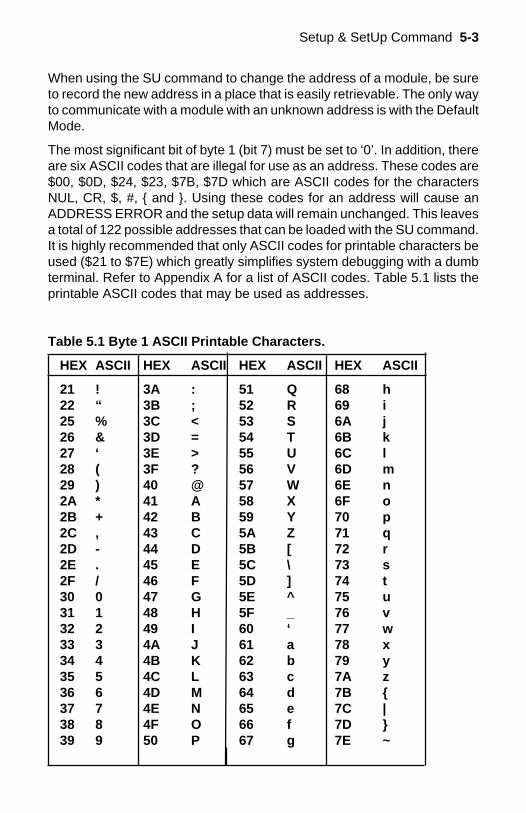
The most significant bit of byte 1 (bit 7) must be set to ‘0’. In addition, thereare six ASCII codes that are illegal for use as an address. These codes are$00, $0D, $24, $23, $7B, $7D which are ASCII codes for the charactersNUL, CR, $, #, and . Using these codes for an address will cause anADDRESS ERROR and the setup data will remain unchanged. This leavesa total of 122 possible addresses that can be loaded with the SU command.It is highly recommended that only ASCII codes for printable characters beused ($21 to $7E) which greatly simplifies system debugging with a dumbterminal. Refer to Appendix A for a list of ASCII codes. Table 5.1 lists theprintable ASCII codes that may be used as addresses.
Table 5.1 Byte 1 ASCII Printable Characters.
HEX ASCII HEX ASCII HEX ASCII HEX ASCII
21 ! 3A : 51 Q 68 h22 “ 3B ; 52 R 69 i25 % 3C < 53 S 6A j26 & 3D = 54 T 6B k27 ‘ 3E > 55 U 6C l28 ( 3F ? 56 V 6D m29 ) 40 @ 57 W 6E n2A * 41 A 58 X 6F o2B + 42 B 59 Y 70 p2C , 43 C 5A Z 71 q2D - 44 D 5B [ 72 r2E . 45 E 5C \ 73 s2F / 46 F 5D ] 74 t30 0 47 G 5E ^ 75 u31 1 48 H 5F _ 76 v32 2 49 I 60 ‘ 77 w33 3 4A J 61 a 78 x34 4 4B K 62 b 79 y35 5 4C L 63 c 7A z36 6 4D M 64 d 7B 37 7 4E N 65 e 7C |38 8 4F O 66 f 7D 39 9 50 P 67 g 7E ~
5-4 D1000 USERS MANUALByte 2Byte 2 is used to configure some of the characteristics of the communica-tions channel; linefeeds, parity, and baud rate.
LinefeedsThe most significant bit of byte 2 (bit 7) controls linefeed generation by themodule. This option can be useful when using the module with a dumbterminal. All responses from the D1000 are terminated with a carriage return(ASCII $0D). Most terminals will generate a automatic linefeed when acarriage return is detected. However, for terminals that do not have thiscapability, the D1000 module can generate the linefeed if desired. By settingbit 7 to ‘1’ the module will send a linefeed (ASCII $0A) before and after eachresponse. If bit 7 is cleared (0), no linefeeds are transmitted.
When using the ‘#’ command prompt, the linefeed characters are notincluded in the checksum calculation.
ParityBits 5 and 6 select the parity to be used by the module. Bit 5 turns the parityon and off. If bit 5 is ‘0’, the parity of the command string is ignored and theparity bit of characters transmitted by the module is set to ‘1’.
If bit 5 is ‘1’, the parity of command strings is checked and the parity ofcharacters output by the module is calculated as specified by bit 6.
If bit 6 is ‘0’, parity is even; if bit 6 is ‘1’, parity is odd.
If a parity error is detected by the module, it will respond with a PARITYERROR message. This is usually caused by noise on the communicationsline.
If parity setup values are changed with the SU command, the response tothe SU command will be transmitted with the old parity setup. The new paritysetup becomes effective immediately after the response message from theSU command.Baud Rate
Bits 0-3 specify the communications baud rate. The baud rate can beselected from ten values between 300 and 115200 baud. Refer to Table 5.2for the desired code.
The baud rate selection is the only setup data that is not implementeddirectly after an SU command. In order for the baud rate to be actuallychanged, a module reset must occur. A reset is performed by sending aRemote Reset (RR) command (see Communications) or powering down.This extra level of write protection is necessary to ensure that communica-tions to the module is not accidently lost. This is very important when
Setup & SetUp Command 5-5
changing the baud rate of an RS-232C string. For more information onchanging baud rate, refer to Chapter 3.
Let’s run through an example of changing the baud rate. Assume our samplemodule contains the setup data value of ‘31070080’. Byte 2 is ‘07’. Byreferring to the SU command chart we can determine that the module is setfor no linefeeds, no parity, and baud rate 300. If we perform the Read Setupcommand with this module we would get:
Command: $1RSResponse: *31070080
Let’s say we wish to change the baud rate to 9600 baud. The code for 9600baud is ‘0010’ (from Table 5.2). This would change byte 2 to ‘02’. To performthe SU command we must first send a Write Enable command because SUis write protected:
Command: $1WEResponse: *
Command: $1SU31020080Response: *
This sequence of messages is done in 300 baud because that was theoriginal baud rate of the module. The module remains in 300 baud after thissequence. We can use the Read Setup (RS) command to check the setupdata:
Command: $1RSResponse: *31020080
Notice that although the module is communicating in 300 baud, the setupdata indicates a baud rate of 9600 (byte 2 = ‘02’). To actually change thebaud rate to 9600, send a Remote Reset (RR) command (RR is writeprotected):
Command: $1WEResponse: *
Command: $1RRResponse: *
Up to this point all communications have been sent at 300 baud. The modulewill not respond to any further communications at 300 baud because it is nowrunning at 9600 baud. At this point the host computer or terminal must be setto 9600 baud to continue operation.
If the module does not respond to the new baud rate, most likely the setupdata is incorrect. Try various baud rates from the host until the module
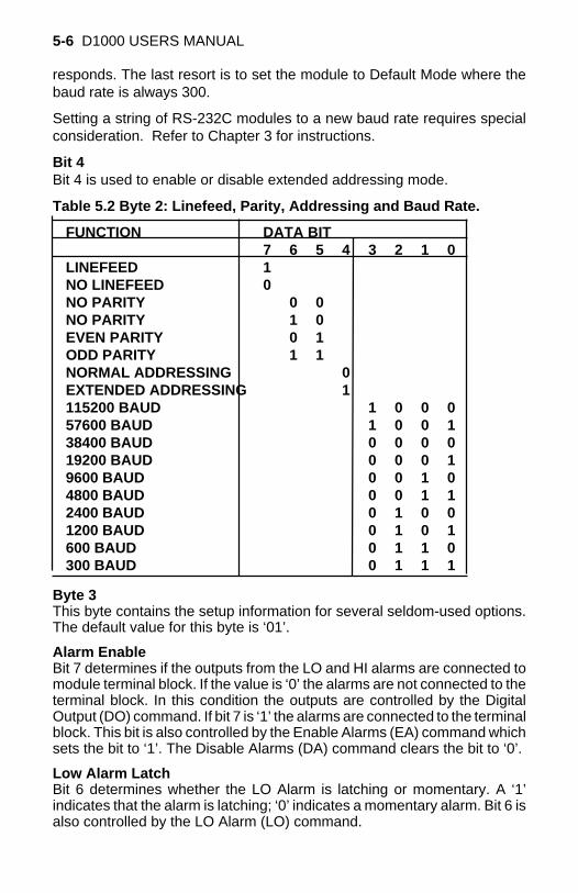
5-6 D1000 USERS MANUAL
responds. The last resort is to set the module to Default Mode where thebaud rate is always 300.
Setting a string of RS-232C modules to a new baud rate requires specialconsideration. Refer to Chapter 3 for instructions.
Bit 4Bit 4 is used to enable or disable extended addressing mode.
Table 5.2 Byte 2: Linefeed, Parity, Addressing and Baud Rate.
FUNCTION DATA BIT7 6 5 4 3 2 1 0
LINEFEED 1NO LINEFEED 0NO PARITY 0 0NO PARITY 1 0EVEN PARITY 0 1ODD PARITY 1 1NORMAL ADDRESSING 0EXTENDED ADDRESSING 1115200 BAUD 1 0 0 057600 BAUD 1 0 0 138400 BAUD 0 0 0 019200 BAUD 0 0 0 19600 BAUD 0 0 1 04800 BAUD 0 0 1 12400 BAUD 0 1 0 01200 BAUD 0 1 0 1600 BAUD 0 1 1 0300 BAUD 0 1 1 1
Byte 3This byte contains the setup information for several seldom-used options.The default value for this byte is ‘01’.
Alarm EnableBit 7 determines if the outputs from the LO and HI alarms are connected tomodule terminal block. If the value is ‘0’ the alarms are not connected to theterminal block. In this condition the outputs are controlled by the DigitalOutput (DO) command. If bit 7 is ‘1’ the alarms are connected to the terminalblock. This bit is also controlled by the Enable Alarms (EA) command whichsets the bit to ‘1’. The Disable Alarms (DA) command clears the bit to ‘0’.
Low Alarm LatchBit 6 determines whether the LO Alarm is latching or momentary. A ‘1’indicates that the alarm is latching; ‘0’ indicates a momentary alarm. Bit 6 isalso controlled by the LO Alarm (LO) command.

Setup & SetUp Command 5-7
High Alarm LatchBit 5 determines whether the HI Alarm is latching or momentary. A’1'indicates latching. Bit 5 is also controlled individually by the HI Alarm (HI)command.
Disable CJCRTD 3/4 WireTrigger Edge SelectThe setup information stored in bit 4 has different meanings depending onthe D1000 model number.
Disable CJC; this function pertains only to the D1300 series of thermo-couple input modules. If the bit is set to ‘1’ the Cold Junction Compensationis disabled. The module calculates the temperature output with a fixed coldjunction temperature of 0 degrees Celsius. This setup is useful for calibratingthe module or in cases where remote CJC is used. Normally this bit is clearedto ‘0’.
RTD 3/4 Wire; this function pertains only to the D1400 series of RTD inputmodules. If the bit is set to ‘1’, the module provides the correct lead-compensation calculation for 4-wire RTD’s. If the bit is cleared to ‘0’, themodule calculates the correct lead compensation for 3-wire RTD’s. Meas-urement errors may result if the module is not set to the correct sensor type.This function has no affect on D145X or D146X Thermistor inputs.
Celsius/FahrenheitThe default scaling for temperature output modules is Celsius which isselected by making bit 3 = 0. To change the scaling to Fahrenheit, set bit 3to ‘1’. All modules that do not have temperature output must have bit 3cleared to zero. The scaling factors are operative only on the sensor data;HI and LO limits and setpoints must be modified by appropriate commandsto reflect a scaling change (see Figure 2.1).
EchoWhen bit 2 is set to ‘1’, the D1000 module will retransmit any characters ithas received on the communications line. This option is necessary to ‘daisy-chain’ multiple RS-232C modules. Echo is optional for systems with a singleRS-232C module. Bit 2 must be cleared to ‘0’ on RS-485 models. SeeChapter 3 for a more complete description.
DelayBits 0 and 1 specify a minimum turn-around delay between a command andthe module response. This delay time is useful on host systems that are notfast enough to capture data from quick-responding commands such as RD.This is particularly true for systems that use software UART’s. The specified
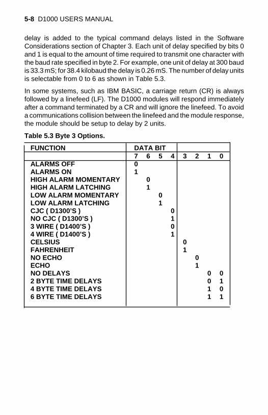
5-8 D1000 USERS MANUAL
delay is added to the typical command delays listed in the SoftwareConsiderations section of Chapter 3. Each unit of delay specified by bits 0and 1 is equal to the amount of time required to transmit one character withthe baud rate specified in byte 2. For example, one unit of delay at 300 baudis 33.3 mS; for 38.4 kilobaud the delay is 0.26 mS. The number of delay unitsis selectable from 0 to 6 as shown in Table 5.3.
In some systems, such as IBM BASIC, a carriage return (CR) is alwaysfollowed by a linefeed (LF). The D1000 modules will respond immediatelyafter a command terminated by a CR and will ignore the linefeed. To avoida communications collision between the linefeed and the module response,the module should be setup to delay by 2 units.
Table 5.3 Byte 3 Options.
FUNCTION DATA BIT7 6 5 4 3 2 1 0
ALARMS OFF 0ALARMS ON 1HIGH ALARM MOMENTARY 0HIGH ALARM LATCHING 1LOW ALARM MOMENTARY 0LOW ALARM LATCHING 1CJC ( D1300’S ) 0NO CJC ( D1300’S ) 13 WIRE ( D1400’S ) 04 WIRE ( D1400’S ) 1CELSIUS 0FAHRENHEIT 1NO ECHO 0ECHO 1NO DELAYS 0 02 BYTE TIME DELAYS 0 14 BYTE TIME DELAYS 1 06 BYTE TIME DELAYS 1 1
Setup & SetUp Command 5-9Byte 4This setup byte specifies the number of displayed digits and the digital filtertime constants.
Number of displayed digitsFor ease of use, the data outputs of all modules are standardized to acommon 7-digit output consisting of sign, 5 digits, decimal point, and twomore digits. Typical output data looks like: +00100.00. However, best-caseresolution of the A/D converter is 1 part in 32,768. In some cases, theresolution of the output format is much greater than the resolution of themeasurement system. In such cases, the trailing digits of the responsewould display meaningless information. Bits 6 and 7 are used to inserttrailing zeros into the output data to limit the output resolution and mask offmeaningless digits.
Bit 7 Bit 6
0 0 XXXX0.00 (4 displayed digits)0 1 XXXXX.00 (5 displayed digits)1 0 XXXXX.X0 (6 displayed digits)1 1 XXXXX.XX (7 displayed digits)
For example, the D1411 model for RTD’s has 0.1 degree output resolution.The appropriate number of digits for this module is 6, to mask off the 0.01digit which has no meaningful data. In some cases, the user may want to limitthe output resolution to 1 degree. To do this, select bits 6 and 7 to display5 digits. With this selection, the right-most two digits will always be set to ‘0’.
The number of displayed digits affects only data received from an RD or NDcommand.
Large Signal Filter, Bits 3,4,5Small Signal Filter, Bits 0,1,2The modules contain a versatile single-pole, low-pass digital filter to smoothout unwanted noise caused by interference or small signal variations. Thedigital filter offers many advantages over traditional analog filters. Thefiltering action is done completely in firmware and is not affected bycomponent drifts, offsets, and circuit noise typically found in analog filters.The filter time constant is programmable through the SetUp (SU) commandand can be changed at any time, even if the module is remote from the host.
The digital filter features separate time constants for large and small signalvariations. The Large Signal Filter time constant is controlled by bits 3,4,5.This time constant is used when large signal variations are present on theinput. The Small Signal Filter time constant is controlled by bits 0,1,2. Thisfilter time constant is automatically selected when input signal variations aresmall. The microprocessor in the module automatically selects the correct
5-10 D1000 USERS MANUAL
filter constant after every A/D conversion. The constant selected dependson the magnitude of the change of the input signal and the setup for thenumber of digits displayed. The microprocessor always keeps the value ofthe last calculated output to compare to a new data conversion. If the newdata differs from the last output by more than ten counts of the last displayeddigit, the large signal time constant is used in the digital filter. If the result ofthe most recent A/D conversion differs from the last output value by less thanten counts of the last displayed digit, the small signal time constant is used.Let’s look at an example:
The D1411 RTD module has a standard output resolution of 0.1 degrees.The standard number-of-displayed-digits setup for this module is 6 digits,from byte 4 of the setup data. Therefore, the large signal filter will be selectedif a new input conversion differs from the previous value by > 1.0 degree:
Previous data New data Filter selected+00100.00 +00100.50 small+00100.00 +00101.50 large+00100.00 +00099.90 small+00100.00 +00098.90 large-00050.50 -00050.00 small-00050.50 -00060.00 small
If the number of displayed digits is changed to reduce output resolution, filterselection is also affected. If the number of displayed digits in the previousexample is changed to 5, the output resolution becomes 1.0 degree.
In this case the large signal time constant is used if the new reading differsfrom the old by more than 10.0 degrees:
Previous data New data Filter selected+00100.00 +00105.00 small+00100.00 +00111.00 large+00100.00 +00091.00 small+00100.00 +00085.00 large-00050.00 -00045.00 small-00050.00 -00039.00 large
Large Signal Time ConstantThe large signal filter time constant is specified by bits 3,4,5 of byte 4. It maybe specified from 0 (no filter) to 16 seconds. The time constant for a first-order filter is the time required for the output to reach 63% of its final valuefor a step input.
Setup & SetUp Command 5-11
Small Signal Time ConstantBits 0,1, 2 specify the filter time constant for small signals. Its values aresimilar to the ones for the large signal filter. Most sensors can benefit froma small amount of small signal filtering such as T = 0.5 seconds In mostapplications, the small signal time constant should be larger than the largesignal time constant. This gives stable readings for steady-state inputs whileproviding fast response to large signal changes.
Table 5.4 Byte 4 Displayed Digits and Filter Time Constants.
BYTE 4FUNCTION DATA BIT
7 6 5 4 3 2 1 0+XXXX0.00 DISPLAYED DIGITS 0 0+XXXXX.00 DISPLAYED DIGITS 0 1+XXXXX.X0 DISPLAYED DIGITS 1 0+XXXXX.XX DISPLAYED DIGITS 1 1NO LARGE SIGNAL FILTERING 0 0 00.25 SECOND TIME CONSTANT 0 0 10.5 SECOND TIME CONSTANT 0 1 01.0 SECOND TIME CONSTANT 0 1 12.0 SECOND TIME CONSTANT 1 0 04.0 SECOND TIME CONSTANT 1 0 18.0 SECOND TIME CONSTANT 1 1 016.0 SECOND TIME CONSTANT 1 1 1NO SMALL SIGNAL FILTERING 0 0 00.25 SECOND TIME CONSTANT 0 0 10.5 SECOND TIME CONSTANT 0 1 01.0 SECOND TIME CONSTANT 0 1 12.0 SECOND TIME CONSTANT 1 0 04.0 SECOND TIME CONSTANT 1 0 18.0 SECOND TIME CONSTANT 1 1 016.0 SECOND TIME CONSTANT 1 1 1
Setup HintsUntil you become completely familiar with the SetUp command, the bestmethod of changing setups is to change one parameter at a time and to verifythat the change has been made correctly. Attempting to modify all the setupsat once can often lead to confusion. If you reach a state of total confusion,the best recourse is to reload the factory setup shown in Table 5.5 and tryagain, changing one parameter at a time. Use the Read Setup (RS)command to examine the setup information currently in the module as abasis for creating a new setup.
For example: Assume you have a D1111 unit and you wish to set the unit
5-12 D1000 USERS MANUAL
to echo so that it may be used in a daisy-chain (See Communications). Readout the current setup with the Read Setup command:
Command: $1RSResponse: *310701C2
By referring to Table 5.3, we find that the echo is controlled by bit 2 of byte3. From the RS command we see that byte 3 is currently set to 01. This isthe hexadecimal representation of binary 0000 0001. To set echo, bit 2 mustbe set to ‘1’. This results in binary 0000 0101. The new hexadecimal valueof byte 3 is 05. To perform the SU command, use the data read out with theRS command, changing only byte 3:
Command: $1WE (SU is write-protected)Response: *
Command: $1SU310705C2Response: *
Verify that the module is echoing characters and the setup is correct.
By using the RS command and changing one setup parameter at a time, anyproblems associated with incorrect setups may be identified immediately.Once a satisfactory setup has been developed, record the setup value anduse it to configure similar modules.
If you commit an error in using the SetUp command, it is possible to losecommunications with the module. In this case, it may be necessary to usethe Default Mode to re-establish communications.
The DA, EA, HI, and LO commands affect some of the bits of the setup datathat are associated with alarms. If these commands are performed, thesetup data read back with the Read Setup command may not correspondexactly with the data previously written with the SetUp command.
Table 5.5 Factory Setups by Model.(All modules from the factory are set for address ‘1’, 300 baud, no parity)
Model Setup Message
D111X, D115X, D121X, D123X, D125X 310701C2D112X, D124X 31070182D110X, D113X, D114X 31070142D13XX, D155X, D156X 31070142D141X, D142X, D143X, D146X 31070182D145X, D15XX 310701C2D16XX 310701C0D170X 31070100
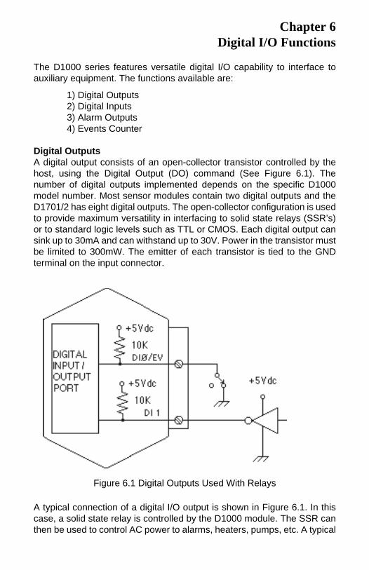
The D1000 series features versatile digital I/O capability to interface toauxiliary equipment. The functions available are:
1) Digital Outputs2) Digital Inputs3) Alarm Outputs4) Events Counter
Digital OutputsA digital output consists of an open-collector transistor controlled by thehost, using the Digital Output (DO) command (See Figure 6.1). Thenumber of digital outputs implemented depends on the specific D1000model number. Most sensor modules contain two digital outputs and theD1701/2 has eight digital outputs. The open-collector configuration is usedto provide maximum versatility in interfacing to solid state relays (SSR’s)or to standard logic levels such as TTL or CMOS. Each digital output cansink up to 30mA and can withstand up to 30V. Power in the transistor mustbe limited to 300mW. The emitter of each transistor is tied to the GNDterminal on the input connector.
Chapter 6Digital I/O Functions
Figure 6.1 Digital Outputs Used With Relays
A typical connection of a digital I/O output is shown in Figure 6.1. In thiscase, a solid state relay is controlled by the D1000 module. The SSR canthen be used to control AC power to alarms, heaters, pumps, etc. A typical
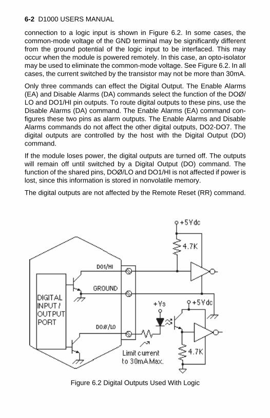
6-2 D1000 USERS MANUAL
connection to a logic input is shown in Figure 6.2. In some cases, thecommon-mode voltage of the GND terminal may be significantly differentfrom the ground potential of the logic input to be interfaced. This mayoccur when the module is powered remotely. In this case, an opto-isolatormay be used to eliminate the common-mode voltage. See Figure 6.2. In allcases, the current switched by the transistor may not be more than 30mA.
Only three commands can effect the Digital Output. The Enable Alarms(EA) and Disable Alarms (DA) commands select the function of the DOØ/LO and DO1/HI pin outputs. To route digital outputs to these pins, use theDisable Alarms (DA) command. The Enable Alarms (EA) command con-figures these two pins as alarm outputs. The Enable Alarms and DisableAlarms commands do not affect the other digital outputs, DO2-DO7. Thedigital outputs are controlled by the host with the Digital Output (DO)command.
If the module loses power, the digital outputs are turned off. The outputswill remain off until switched by a Digital Output (DO) command. Thefunction of the shared pins, DOØ/LO and DO1/HI is not affected if power islost, since this information is stored in nonvolatile memory.
The digital outputs are not affected by the Remote Reset (RR) command.
Figure 6.2 Digital Outputs Used With Logic
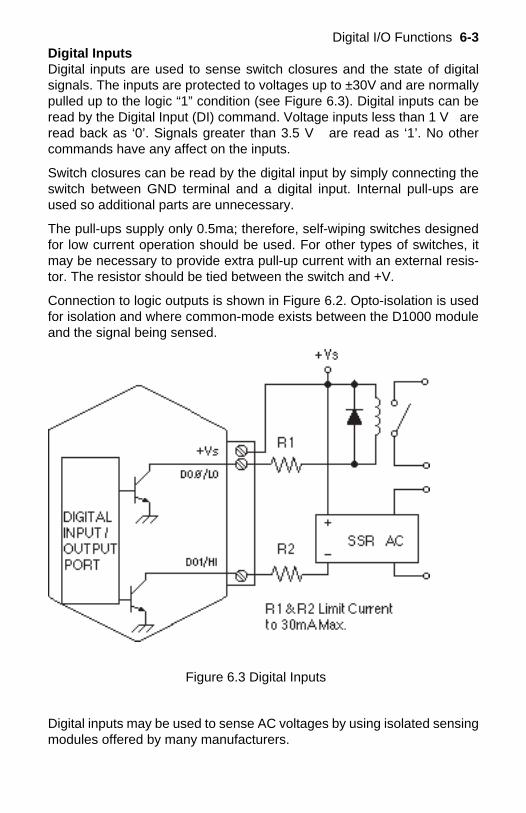
Digital I/O Functions 6-3Digital InputsDigital inputs are used to sense switch closures and the state of digitalsignals. The inputs are protected to voltages up to ±30V and are normallypulled up to the logic “1” condition (see Figure 6.3). Digital inputs can beread by the Digital Input (DI) command. Voltage inputs less than 1 V areread back as ‘0’. Signals greater than 3.5 V are read as ‘1’. No othercommands have any affect on the inputs.
Switch closures can be read by the digital input by simply connecting theswitch between GND terminal and a digital input. Internal pull-ups areused so additional parts are unnecessary.
The pull-ups supply only 0.5ma; therefore, self-wiping switches designedfor low current operation should be used. For other types of switches, itmay be necessary to provide extra pull-up current with an external resis-tor. The resistor should be tied between the switch and +V.
Connection to logic outputs is shown in Figure 6.2. Opto-isolation is usedfor isolation and where common-mode exists between the D1000 moduleand the signal being sensed.
Digital inputs may be used to sense AC voltages by using isolated sensingmodules offered by many manufacturers.
Figure 6.3 Digital Inputs
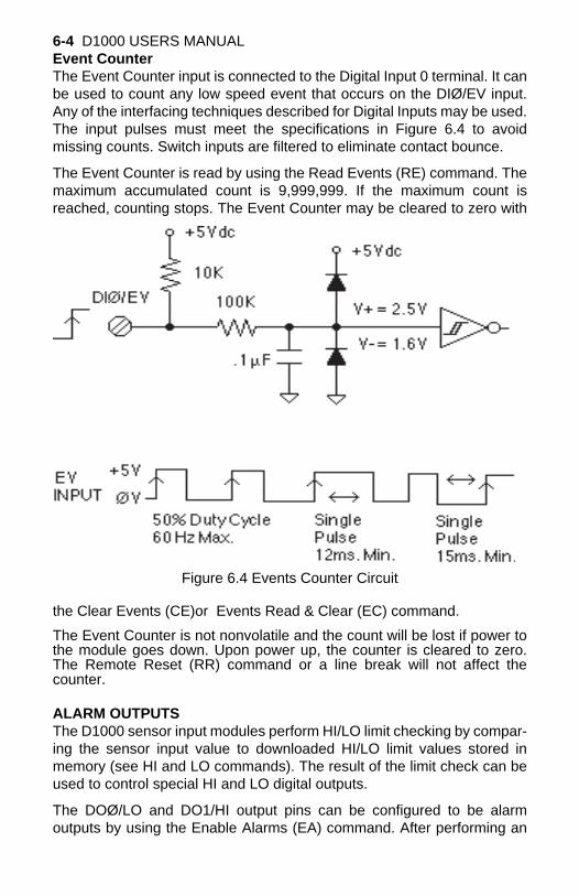
6-4 D1000 USERS MANUALEvent CounterThe Event Counter input is connected to the Digital Input 0 terminal. It canbe used to count any low speed event that occurs on the DIØ/EV input.Any of the interfacing techniques described for Digital Inputs may be used.The input pulses must meet the specifications in Figure 6.4 to avoidmissing counts. Switch inputs are filtered to eliminate contact bounce.
The Event Counter is read by using the Read Events (RE) command. Themaximum accumulated count is 9,999,999. If the maximum count isreached, counting stops. The Event Counter may be cleared to zero with
the Clear Events (CE)or Events Read & Clear (EC) command.
The Event Counter is not nonvolatile and the count will be lost if power tothe module goes down. Upon power up, the counter is cleared to zero.The Remote Reset (RR) command or a line break will not affect thecounter.
ALARM OUTPUTSThe D1000 sensor input modules perform HI/LO limit checking by compar-ing the sensor input value to downloaded HI/LO limit values stored inmemory (see HI and LO commands). The result of the limit check can beused to control special HI and LO digital outputs.
The DOØ/LO and DO1/HI output pins can be configured to be alarmoutputs by using the Enable Alarms (EA) command. After performing an
Figure 6.4 Events Counter Circuit
Digital I/O Functions 6-5
EA command, the state of the DOØ/LO and DO1/HI pins will be controlledby the alarm settings. The EA command does not affect the other digitaloutputs, DO2-DO8. The Disable Alarms (DA) command is used to discon-nect the alarms from the output pins whereupon they are controlled by theDigital Output (DO) command.
Since the Alarm Outputs share the same circuits with the Digital Outputs,all electrical interfacing considerations are the same.
Alarm limit values are loaded into the module with the Low limit (LO) andHi limit (HI) commands. The limit values are stored in nonvolatile memoryso they will not be lost when power is removed. The HI and LO commandsare also used to specify whether the alarms are momentary or latching. Ifan alarm is specified as momentary, the alarm is activated as long as thealarm condition exists. The alarm output will turn off when the input iswithin limits. A Latching alarm is activated when the specified limit isexceeded and will remain on even if the input value returns within limits. ALatching alarm can be turned off with the Clear Alarms (CA) command.The HI alarm output is turned on (sinking current) when the measuredsensor input is greater than the high limit loaded in with the HI command.The LO alarm output is turned on (sinking current) when the input value isless than the stored low limit.
The alarm limit values may be read back at any time using the Read Low(RL) or Read High (RH) commands.
ON-OFF CONTROLLERSThe alarm capabilities of the D1000 sensor-input modules may be utilizedto construct simple ON-OFF controllers that operate without host interven-tion. In fact, since all the alarm information is stored in nonvolatile memory,the module can act as a stand-alone controller with the communicationslines disconnected.
The simplest controller connection is to use a momentary alarm output tocontrol the process. A typical application would have a temperature inputmodule controlling a heater, as shown in Figure 6.5. To maintain a con-stant temperature, set the low limit to the setpoint desired and specify thealarm output to be momentary. Use the LO alarm output to control theheater. If the temperature measurement exceeds the low limit, the heater
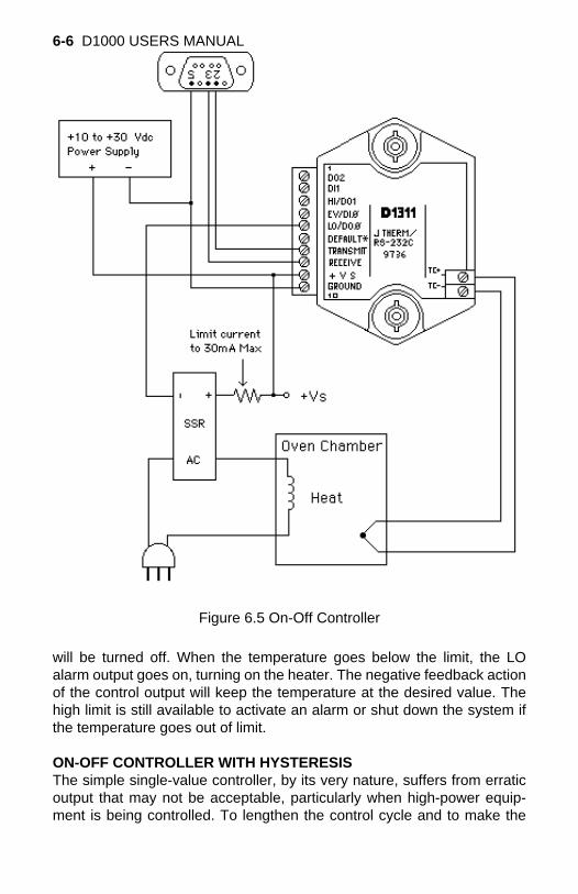
6-6 D1000 USERS MANUAL
Figure 6.5 On-Off Controller
will be turned off. When the temperature goes below the limit, the LOalarm output goes on, turning on the heater. The negative feedback actionof the control output will keep the temperature at the desired value. Thehigh limit is still available to activate an alarm or shut down the system ifthe temperature goes out of limit.
ON-OFF CONTROLLER WITH HYSTERESISThe simple single-value controller, by its very nature, suffers from erraticoutput that may not be acceptable, particularly when high-power equip-ment is being controlled. To lengthen the control cycle and to make the
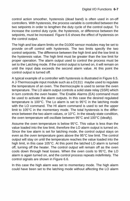
Digital I/O Functions 6-7
control action smoother, hysteresis (dead band) is often used in on-offcontrollers. With hysteresis, the process variable is controlled between thetwo setpoints in order to lengthen the duty cycle of the control output. Toincrease the control duty cycle, the hysteresis, or difference between thesetpoints, must be increased. Figure 6.6 shows the effect of hysteresis onthe control output.
The high and low alarm limits on the D1000 sensor modules may be set toprovide on-off control with hysteresis. The two limits specify the twocontrol setpoints. The difference between the high limit and the low limit isthe hysteresis value. The high limit must be greater than the low limit forproper operation. The alarm output used to control the process must beset to the Latching mode. If the control output is turned on, it will remain onuntil the input data exceeds the second alarm value. At this point thecontrol output is turned off.
A typical example of a controller with hysteresis is illustrated in Figure 6.5.A J-Thermocouple input module such as a D1311 maybe used to regulatethe temperature of an oven. The thermocouple is used to sense the oventemperature. The LO alarm output controls a solid state relay (SSR) whichin turn controls the oven heater. The Enable Alarms (EA) command mustbe used to activate the alarm outputs. In this case the desired regulatedtemperature is 100°C. The Lo alarm is set to 95°C in the latching modewith the LO command. The HI alarm command is used to set the upperlimit to 105°C in the momentary mode. The total hysteresis is the differ-ence between the two alarm values, or 10°C. In the steady state condition,the oven temperature will oscillate between 95°C and 100°C (ideally).
Assume the oven temperature is below 95°C. This value is less than thevalue loaded into the low limit, therefore the LO alarm output is turned on.Since the low alarm is set for latching mode, the control output stays oneven as the oven temperature goes above the 95°C low limit. The controloutput will stay on until the temperature reaches the value loaded into thehigh limit, in this case 105°C. At this point the latched LO alarm is turnedoff, turning off the heater. The control output will remain off as the ovencools down through heat losses. When the oven cools to 95°C, the LOalarm is again turned on, and the control process repeats indefinitely. Thecontrol signals are shown in Figure 6.6.
In this case the high alarm was set to momentary mode. The high alarmcould have been set to the latching mode without affecting the LO alarm
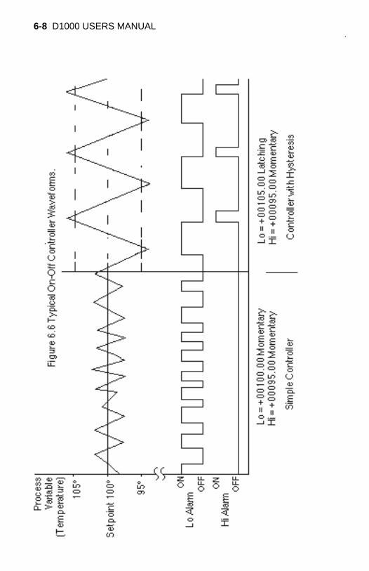
6-8 D1000 USERS MANUAL
Digital I/O Functions 6-9
output. However, the output at the HI alarm terminal would change. If thehigh alarm is set to Latching, the alarm output is simply the complement ofthe LO alarm. Either alarm output may be used for control depending onwhich one will result in negative feedback. For example, in a refrigerationsystem, the HI output may be used to control the refrigeration compressorand the low alarm value is used only to set the desired hysteresis value.
SETPOINTIn the preceding example, the low and high alarm limits are used to specifya hysteresis value around a desired setpoint. To change the desiredsetpoint, both the low and high alarm values must be changed. In this typeof controller operation, the Read Data (RD) or New Data (ND) commandswill read out the actual value of the process variable.
The D1000 modules provide a means of downloading a setpoint valuewithout affecting the desired hysteresis by using the Setpoint (SP) com-mand. The Setpoint command is used to load the desired control valueinto the output offset register (see Figure 2.1). The value in the outputoffset register is always added to the data derived from the sensor input.For instance, if the sensor data is +00100.00 and the output offset registercontains +00050.00, a Read Data command will yield an output of+00150.00. The Setpoint command loads a value into the offset register tonull out the sensor data. If the command $1SP+00100.00 is given to amodule with address 1, the effect of the command is to load the outputoffset register with -00100.00. An RD command will now result in thedeviation of the input data from the downloaded setpoint value.
A careful look at Figure 2.1 will reveal that the alarm limits are checkedafter the output offset is added the input data. To construct a controllerusing the SP command, the high and low alarms must be loaded with thehysteresis values referred to the deviation from the setpoint value. In theoven controller example, the hysteresis was set to ±5°C from the desiredcontrol temperature of 100°C. When using the SP command, the high limitwould be set to +00005.00 and the low limit would be set to -00005.00 toget the same hysteresis affect. The Latching modes of the alarm limits areused in the same manner as previously described.
Let’s look at the oven controller again using the Setpoint command. Thedesired oven temperature is 100°C. This time we’ll use the SP commandto load the 100°C value into the temperature module. As before, we wouldlike a hysteresis band of ±5°C from the nominal temperature of 100°C. Inthis case, set the low limit to -00005.00 latching and the high limit to+00005.00. The high and low limits are now used solely to define thehysteresis band. If the oven temperature is low, say 90°C, the resultingdeviation from the setpoint of 100°C is -10°C. This value exceeds the low

6-10 D1000 USERS MANUAL
limit and the LO alarm control output is turned on to activate the heater.The latched LO alarm will stay on until the measured temperature exceeds105°C. At this point the deviation from the setpoint is greater than ±5°C,the value loaded into the high limit. When the high limit is exceeded, thelatched LO alarm output is turned off, turning off the heater. The controlaction is identical to the controller described in Figure 6.6.
The benefit of using SP command is that only one command is necessaryto change the setpoint value. The hysteresis is stored in the HI and LOalarm registers and does not have to be changed when a new setpoint isused.
The SP command makes it particularly easy to construct a controllerwhose setpoint is a time varying function downloaded from a host com-puter. The SP command can also be used without control functionswhenever a deviation output is desired.
The setpoint value may be read back by using the Read Zero (RZ)command. The RZ simply reads back the contents of the output offsetregister. The RZ command will always read back the setpoint value withthe sign changed.
The setpoint value is stored in the same register as the output offset trim(see TZ command). In cases where the output offset register is used tohold a calibration trim value, the SP command will erase the trim. In mostcases, an offset calibration trim is not necessary and the trim value wouldread back as +00000.00 using the Read Zero (RZ) command. If the trim isnon-zero, it must be read and stored by the host before the SP commandis executed. To download setpoint values the host must then subtract thetrim value from the desired setpoint to derive the proper data for the SPcommand. To restore the trim, use the SP command to download thenegative of the trim that was previously read back with the RZ command.
D1000 modules may be powered with an unregulated +10 to +30Vdc.Power-supply ripple must be limited to 5V peak-to-peak, and the instanta-neous ripple voltage must be maintained between the 10 and 30 volt limitsat all times. The modules contain a low voltage detection circuit that shutsdown all circuits in the module at approximately 9.5 Vdc. All power supplyspecifications are referred to the module connector; the effects of linevoltage drops must be considered when the module is powered remotely.
All D1000 modules employ an on-board switching regulator to maintaingood efficiency over the 10 to 30 volt input range; therefore the actual currentdraw is inversely proportional to the line voltage. D1000 modules withoutsensor excitation consume a maximum of .75 watts and this figure shouldbe used in determining the power supply current requirement. For example,assume a 24 volt power supply will be used to power four modules. The totalpower requirement is 4 X .75 = 3 watts. The power supply must be able toprovide 3 / 24 = 0.125 amps.
For modules with sensor excitation, consult individual data sheets for powerrequirements.
The low voltage detection circuit shuts down the module at approximately9.5Vdc. If the module is interrogated while in a low power supply condition,the module will not respond. Random NOT READY error messages couldindicate that the power supply voltage is periodically drooping below the 10Vminimum.
In some cases, a small number of modules may be operated by “stealing”power from a host computer or terminal.
Small systems may be powered by using wall-mounted calculator-typemodular power supplies. These units are inexpensive and may be obtainedfrom many retail electronics outlets.
Chapter 7Power Supply

7-2 D1000 USERS MANUAL

Symptom:RS-232 Module is not responding to commandsRS-485 Module is not responding to commandsEvents counter not counting properly.Error in displayed value.Read Data (RD) values are factor of two times normal values.Module responds with ?1 COMMAND ERROR to every command.Characters in each response message appear as graphics characters
• RS-232 Module is not responding to commands1. Using a voltmeter, measure the power supply voltage at the+Vs and GND terminals to verify the power supply voltage is constantlybetween +10 and +30Vdc.
2. Verify using an ohmmeter that there are no breaks in thecommunications data lines.
3. Connect the module to the host computer and power-up each device(module and computer) then using a voltmeter measure the voltage be-tween RECEIVE and GND. This voltage should be approximately - 10Vdc.Repeat the measurement between TRANSMIT and GND terminals andconfirm the voltage value to be approximately -10Vdc. If either of the tworeadings is approximately 0.0Vdc then the communications data lines arewired backwards. Proper communications levels on both TRANSMIT andRECEIVE terminals should idle at -10Vdc.
4. If you are using a serial communications converter (A1000) ensure thatthe communications Baud Rate switch is set to the proper Baud Rate value.
5. Confirm software communications settings in Host computer matchthose values being used by the connected module(s).
6. If the Baud Rate value being used in the application is greater than 300Baud and the module will only communicate 300 Baud then make sure thatthe DEFAULT* terminal is not connected to Ground (GND).
7. If the module(s) are being used in a RS-232 daisy-chain communica-tions configuration then ensure that the "Echo Bit" is enabled in thesetup(SU) message of each module.
8. If the problem is not corrected after completing the steps above thenconnect the module by itself to a Host computer as outlined in Chapter 1.0under "Quick Hook-up". Start the supplied Utility software and please call thefactory for further assistance.
Chapter 8Troubleshooting

8-2 D1000 USERS MANUAL
The D1000 module is initially calibrated at the factory and has a recom-mended calibration interval of one year. Calibration constants are stored inthe EEPROM and may be trimmed using the Trim Span (TS) and Trim Zero(TZ) commands. There are no pots to adjust. Calibration procedure is asfollows.
Voltage and current inputs: clear the output offset register using the ClearZero (CZ) command. Zero trims are not neccessary due to the built-in auto-zero function. Apply a known calibrated voltage or current to the input of themodule. The calibrated stimulus should be adjusted to be near 90% of thefull scale output of the modules for best results. Obviously, the accuracy ofthe calibrated voltage or current must be better than the rated accuracy ofthe module, which in most cases is 0.02% of full scale. Use the Read Data(RD) command to obtain an output reading. If the output corresponds to theapplied input, no calibration is necessary. If the output is in overload, checkthe circuit connections or use a different input value to obtain an output withinthe operating range of the module.
To trim the output, use the Trim Span (TS) command. The argument of theTS command should correspond to the desired module output. Afterperforming the TS command, verify the trim with the RD command. Forexample to trim a D1121 module:
1. Clear the output offset register.
Command: $1WEResponse: * (CZ is write protected)
Command: $1CZResponse: *
2. Apply an input voltage near 90% of rated full scale. In this case we will usea +900mV input voltage that is accurate to at least 0.02%. Obtain an outputreading.
Command: $1RDResponse: *+00900.30
In this case, the output of the module is off by 300µV. To trim:
Command: $1WEResponse: * (TS is write protected)
Command: $1TS+00900.00Response: *
Chapter 9Calibration
9-2 D1000 USERS MANUAL
This sequence will trim the output to +00900.00. Verify:
Command: $1RDResponse: *+00900.00
The module is calibrated.
Thermocouples: Disable the cold junction compensation by setting bit 4 inbyte 3 of the setup data with the SetUp (SU) command. The module maynow be calibrated using a known input voltage. Perform the calibration asdescribed for a voltage input module. Table 9.1 gives recommendedcalibration points. Due to the nonlinear nature of thermocouples, it may benecessary to repeat the TS command to obtain the desired output. Aftercalibration is complete, enable the cold junction compensation by clearingbit 4 in byte 3 of the setup data.
RTD: Use a calibrated resistor mounted directly on the module connector toavoid lead resistance errors. The resistor must be accurate to 0.01% forproper calibration. Recommended calibration points are listed in Table 9.1.Follow the command sequence described for voltage inputs to calibrate themodule. Due to the nonlinear nature of RTD’s it may be necessary to repeatthe TS command to obtain the desired output.
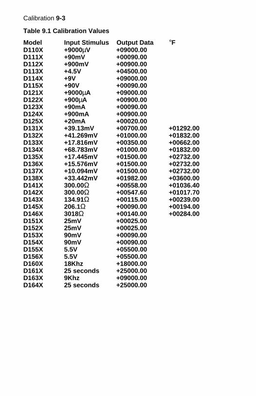
Calibration 9-3
Table 9.1 Calibration Values
Model Input Stimulus Output Data °FD110X +9000µV +09000.00D111X +90mV +00090.00D112X +900mV +00900.00D113X +4.5V +04500.00D114X +9V +09000.00D115X +90V +00090.00D121X +9000µA +09000.00D122X +900µA +00900.00D123X +90mA +00090.00D124X +900mA +00900.00D125X +20mA +00020.00D131X +39.13mV +00700.00 +01292.00D132X +41.269mV +01000.00 +01832.00D133X +17.816mV +00350.00 +00662.00D134X +68.783mV +01000.00 +01832.00D135X +17.445mV +01500.00 +02732.00D136X +15.576mV +01500.00 +02732.00D137X +10.094mV +01500.00 +02732.00D138X +33.442mV +01982.00 +03600.00D141X 300.00Ω +00558.00 +01036.40D142X 300.00Ω +00547.60 +01017.70D143X 134.91Ω +00115.00 +00239.00D145X 206.1Ω +00090.00 +00194.00D146X 3018Ω +00140.00 +00284.00D151X 25mV +00025.00D152X 25mV +00025.00D153X 90mV +00090.00D154X 90mV +00090.00D155X 5.5V +05500.00D156X 5.5V +05500.00D160X 18Khz +18000.00D161X 25 seconds +25000.00D163X 9Khz +09000.00D164X 25 seconds +25000.00

9-4 D1000 USERS MANUAL

Chapter 10Extended Addressing
The D1000 may be configured to a special command format calledExtended Addressing. This mode uses a different prompt, either '' or ''to distinguish it from the regular command syntax. The major differencein syntax for the Extended Addressing mode is that it uses a two-charac-ter address. A typical command in Extended Address mode would looklike this:
Command: 01WEResponse: *
Both the command and response are terminated with carriage returns.Note that the command uses a two-character address, '01.'
There are two benefits to using Extended Addressing with the D1000:
1) Greatly expanded addressing capability.
2) Allow for a more structured addressing method inlarge systems.
With single-byte addressing of the normal command structure, addressspace is limited to 122 points. Extended addressing allows an address-ing range of 249 points.
Structured AddressingEven for a relatively small system, it can be advantageous to employ ahierarchical addressing system as used in Fig. 7.1. This is particularlytrue in systems that consist of many sites that are identical. From a hostsoftware standpoint, each site can be treated identically with the samemodule addresses, with each site having a different D1000 address.
Extended Address SyntaxThe command syntax used with Extended Addressing is quite similar tothe normal protocol. The Extended Address commands are initiated witha '' character (left curly brace, ASCII $7B), or a '' character (right curlybrace, ASCII $7E). The '' prompt is analogous to the '$' prompt in that itreturns the shortest possible response to complete the command. The ''prompt is similar to the '#' prompt in that the command is echoed and achecksum is generated along with the other data necessary to completethe response. The '*' response prompt is used in all command forms.
10-2 D1000 USERS MANUAL
The Extended Address commands use a two-character ASCII address,each character may be one of 122 legal possibilities. Illegal charactersare: NULL ($00), CR ($0D), $ ($24), # ($23), ($7B), and ($7E).
Command examples with Extended Address '01':
Command: 01WEResponse: *
Command: 01WEResponse: *01WE27
Command: 01RSResponse: *31070000 (typical)
Command: 01RSResponse: *01RS31070000BB (typical)
Checksums may be appended to commands:
Command: 01WE78Response: *
All commands that are available with single-byte addressing may beaccessed with Extended Addressing, and vice-versa.
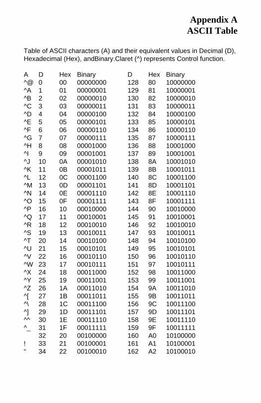
Table of ASCII characters (A) and their equivalent values in Decimal (D),Hexadecimal (Hex), andBinary.Claret (^) represents Control function.
A D Hex Binary D Hex Binary^@ 0 00 00000000 128 80 10000000^A 1 01 00000001 129 81 10000001^B 2 02 00000010 130 82 10000010^C 3 03 00000011 131 83 10000011^D 4 04 00000100 132 84 10000100^E 5 05 00000101 133 85 10000101^F 6 06 00000110 134 86 10000110^G 7 07 00000111 135 87 10000111^H 8 08 00001000 136 88 10001000^I 9 09 00001001 137 89 10001001^J 10 0A 00001010 138 8A 10001010^K 11 0B 00001011 139 8B 10001011^L 12 0C 00001100 140 8C 10001100^M 13 0D 00001101 141 8D 10001101^N 14 0E 00001110 142 8E 10001110^O 15 0F 00001111 143 8F 10001111^P 16 10 00010000 144 90 10010000^Q 17 11 00010001 145 91 10010001^R 18 12 00010010 146 92 10010010^S 19 13 00010011 147 93 10010011^T 20 14 00010100 148 94 10010100^U 21 15 00010101 149 95 10010101^V 22 16 00010110 150 96 10010110^W 23 17 00010111 151 97 10010111^X 24 18 00011000 152 98 10011000^Y 25 19 00011001 153 99 10011001^Z 26 1A 00011010 154 9A 10011010^[ 27 1B 00011011 155 9B 10011011^\ 28 1C 00011100 156 9C 10011100^] 29 1D 00011101 157 9D 10011101^^ 30 1E 00011110 158 9E 10011110^_ 31 1F 00011111 159 9F 10011111
32 20 00100000 160 A0 10100000! 33 21 00100001 161 A1 10100001“ 34 22 00100010 162 A2 10100010
Appendix AASCII Table
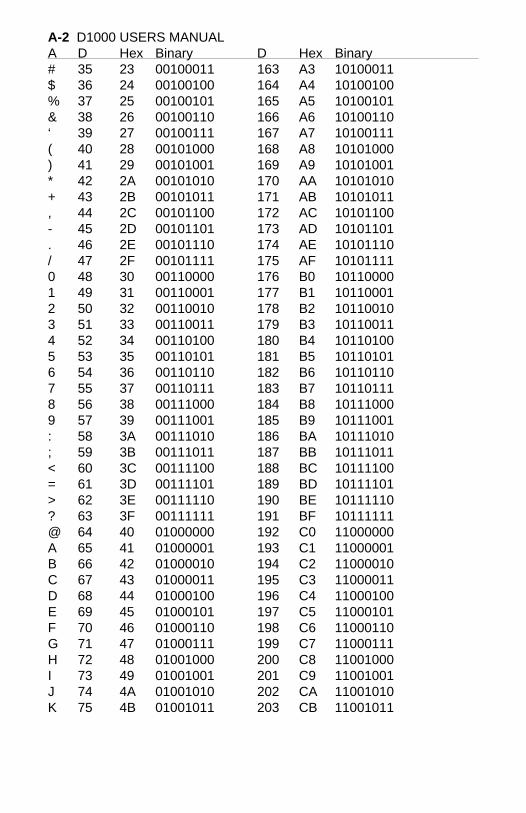
A-2 D1000 USERS MANUALA D Hex Binary D Hex Binary# 35 23 00100011 163 A3 10100011$ 36 24 00100100 164 A4 10100100% 37 25 00100101 165 A5 10100101& 38 26 00100110 166 A6 10100110‘ 39 27 00100111 167 A7 10100111( 40 28 00101000 168 A8 10101000) 41 29 00101001 169 A9 10101001* 42 2A 00101010 170 AA 10101010+ 43 2B 00101011 171 AB 10101011, 44 2C 00101100 172 AC 10101100- 45 2D 00101101 173 AD 10101101. 46 2E 00101110 174 AE 10101110/ 47 2F 00101111 175 AF 101011110 48 30 00110000 176 B0 101100001 49 31 00110001 177 B1 101100012 50 32 00110010 178 B2 101100103 51 33 00110011 179 B3 101100114 52 34 00110100 180 B4 101101005 53 35 00110101 181 B5 101101016 54 36 00110110 182 B6 101101107 55 37 00110111 183 B7 101101118 56 38 00111000 184 B8 101110009 57 39 00111001 185 B9 10111001: 58 3A 00111010 186 BA 10111010; 59 3B 00111011 187 BB 10111011< 60 3C 00111100 188 BC 10111100= 61 3D 00111101 189 BD 10111101> 62 3E 00111110 190 BE 10111110? 63 3F 00111111 191 BF 10111111@ 64 40 01000000 192 C0 11000000A 65 41 01000001 193 C1 11000001B 66 42 01000010 194 C2 11000010C 67 43 01000011 195 C3 11000011D 68 44 01000100 196 C4 11000100E 69 45 01000101 197 C5 11000101F 70 46 01000110 198 C6 11000110G 71 47 01000111 199 C7 11000111H 72 48 01001000 200 C8 11001000I 73 49 01001001 201 C9 11001001J 74 4A 01001010 202 CA 11001010K 75 4B 01001011 203 CB 11001011
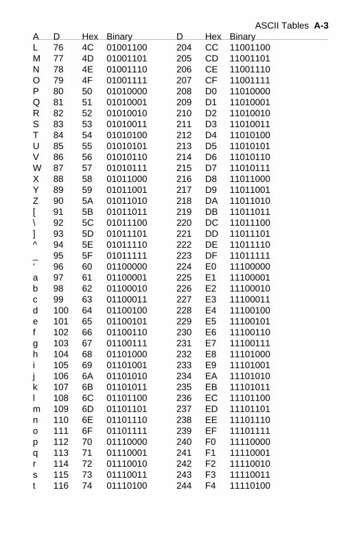
ASCII Tables A-3A D Hex Binary D Hex BinaryL 76 4C 01001100 204 CC 11001100M 77 4D 01001101 205 CD 11001101N 78 4E 01001110 206 CE 11001110O 79 4F 01001111 207 CF 11001111P 80 50 01010000 208 D0 11010000Q 81 51 01010001 209 D1 11010001R 82 52 01010010 210 D2 11010010S 83 53 01010011 211 D3 11010011T 84 54 01010100 212 D4 11010100U 85 55 01010101 213 D5 11010101V 86 56 01010110 214 D6 11010110W 87 57 01010111 215 D7 11010111X 88 58 01011000 216 D8 11011000Y 89 59 01011001 217 D9 11011001Z 90 5A 01011010 218 DA 11011010[ 91 5B 01011011 219 DB 11011011\ 92 5C 01011100 220 DC 11011100] 93 5D 01011101 221 DD 11011101^ 94 5E 01011110 222 DE 11011110_ 95 5F 01011111 223 DF 11011111‘ 96 60 01100000 224 E0 11100000a 97 61 01100001 225 E1 11100001b 98 62 01100010 226 E2 11100010c 99 63 01100011 227 E3 11100011d 100 64 01100100 228 E4 11100100e 101 65 01100101 229 E5 11100101f 102 66 01100110 230 E6 11100110g 103 67 01100111 231 E7 11100111h 104 68 01101000 232 E8 11101000i 105 69 01101001 233 E9 11101001j 106 6A 01101010 234 EA 11101010k 107 6B 01101011 235 EB 11101011l 108 6C 01101100 236 EC 11101100m 109 6D 01101101 237 ED 11101101n 110 6E 01101110 238 EE 11101110o 111 6F 01101111 239 EF 11101111p 112 70 01110000 240 F0 11110000q 113 71 01110001 241 F1 11110001r 114 72 01110010 242 F2 11110010s 115 73 01110011 243 F3 11110011t 116 74 01110100 244 F4 11110100
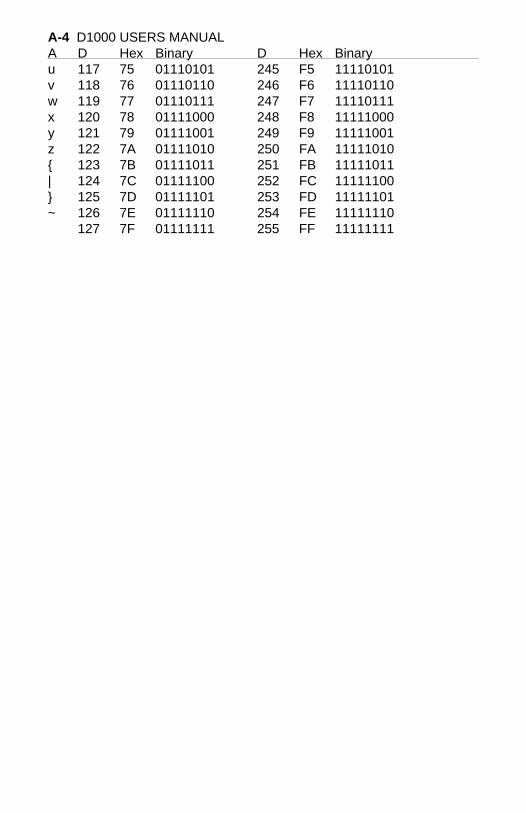
A-4 D1000 USERS MANUALA D Hex Binary D Hex Binaryu 117 75 01110101 245 F5 11110101v 118 76 01110110 246 F6 11110110w 119 77 01110111 247 F7 11110111x 120 78 01111000 248 F8 11111000y 121 79 01111001 249 F9 11111001z 122 7A 01111010 250 FA 11111010 123 7B 01111011 251 FB 11111011| 124 7C 01111100 252 FC 11111100 125 7D 01111101 253 FD 11111101~ 126 7E 01111110 254 FE 11111110
127 7F 01111111 255 FF 11111111
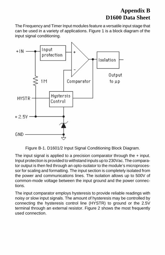
The Frequency and Timer Input modules feature a versatile input stage thatcan be used in a variety of applications. Figure 1 is a block diagram of theinput signal conditioning.
Appendix BD1600 Data Sheet
Figure B-1. D1601/2 Input Signal Conditioning Block Diagram.
The input signal is applied to a precision comparator through the + input.Input protection is provided to withstand inputs up to 230Vac. The compara-tor output is then fed through an opto-isolator to the module’s microproces-sor for scaling and formatting. The input section is completely isolated fromthe power and communications lines. The isolation allows up to 500V ofcommon-mode voltage between the input ground and the power connec-tions.
The input comparator employs hysteresis to provide reliable readings withnoisy or slow input signals. The amount of hysteresis may be controlled byconnecting the hysteresis control line (HYSTR) to ground or the 2.5Vterminal through an external resistor. Figure 2 shows the most frequentlyused connection.
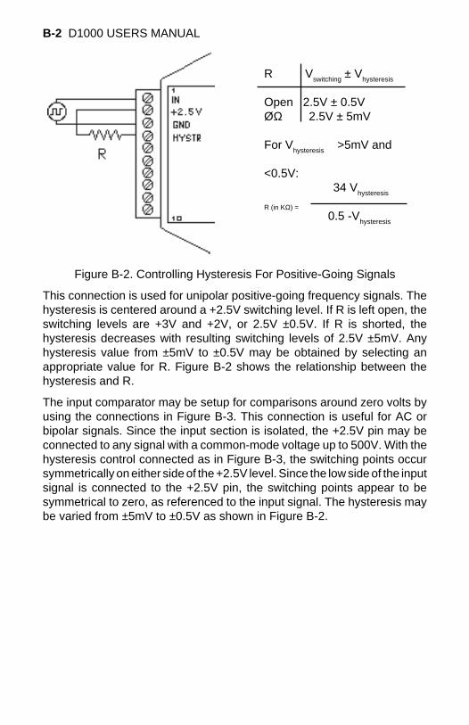
B-2 D1000 USERS MANUAL
Figure B-2. Controlling Hysteresis For Positive-Going Signals
This connection is used for unipolar positive-going frequency signals. Thehysteresis is centered around a +2.5V switching level. If R is left open, theswitching levels are +3V and +2V, or 2.5V ±0.5V. If R is shorted, thehysteresis decreases with resulting switching levels of 2.5V ±5mV. Anyhysteresis value from ±5mV to ±0.5V may be obtained by selecting anappropriate value for R. Figure B-2 shows the relationship between thehysteresis and R.
The input comparator may be setup for comparisons around zero volts byusing the connections in Figure B-3. This connection is useful for AC orbipolar signals. Since the input section is isolated, the +2.5V pin may beconnected to any signal with a common-mode voltage up to 500V. With thehysteresis control connected as in Figure B-3, the switching points occursymmetrically on either side of the +2.5V level. Since the low side of the inputsignal is connected to the +2.5V pin, the switching points appear to besymmetrical to zero, as referenced to the input signal. The hysteresis maybe varied from ±5mV to ±0.5V as shown in Figure B-2.
R Vswitching
± Vhysteresis
Open 2.5V ± 0.5VØΩ 2.5V ± 5mV
For Vhysteresis
>5mV and
<0.5V: 34 V
hysteresis
R (in KΩ) =
0.5 -Vhysteresis
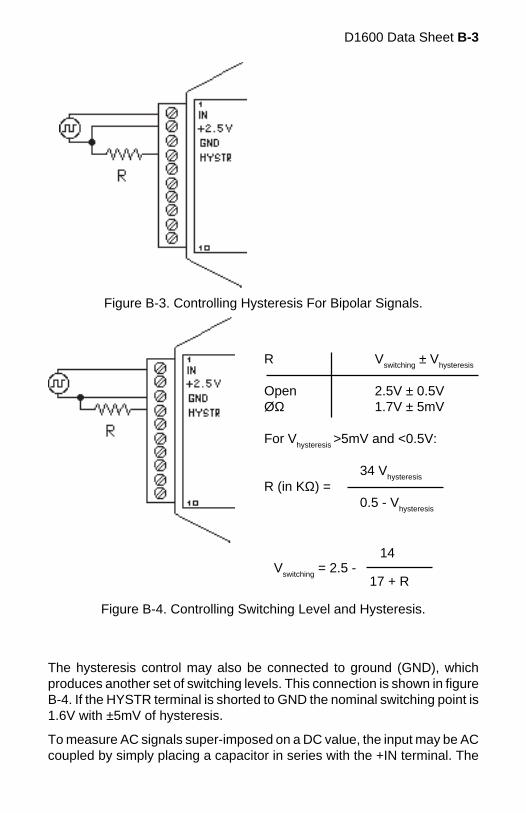
D1600 Data Sheet B-3
Figure B-3. Controlling Hysteresis For Bipolar Signals.
R Vswitching ± Vhysteresis
Open 2.5V ± 0.5VØΩ 1.7V ± 5mV
For Vhysteresis
>5mV and <0.5V:
34 Vhysteresis
R (in KΩ) =0.5 - V
hysteresis
Vswitching
= 2.5 -14
17 + R
The hysteresis control may also be connected to ground (GND), whichproduces another set of switching levels. This connection is shown in figureB-4. If the HYSTR terminal is shorted to GND the nominal switching point is1.6V with ±5mV of hysteresis.
To measure AC signals super-imposed on a DC value, the input may be ACcoupled by simply placing a capacitor in series with the +IN terminal. The
Figure B-4. Controlling Switching Level and Hysteresis.
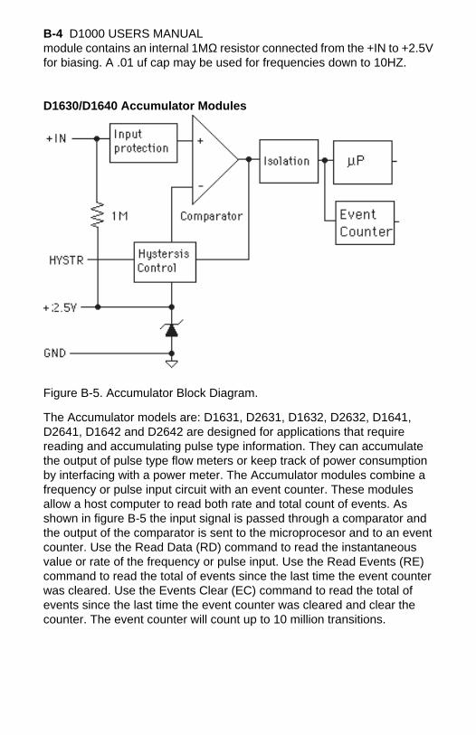
B-4 D1000 USERS MANUALmodule contains an internal 1MΩ resistor connected from the +IN to +2.5Vfor biasing. A .01 uf cap may be used for frequencies down to 10HZ.
D1630/D1640 Accumulator Modules
Figure B-5. Accumulator Block Diagram.
The Accumulator models are: D1631, D2631, D1632, D2632, D1641,D2641, D1642 and D2642 are designed for applications that requirereading and accumulating pulse type information. They can accumulatethe output of pulse type flow meters or keep track of power consumptionby interfacing with a power meter. The Accumulator modules combine afrequency or pulse input circuit with an event counter. These modulesallow a host computer to read both rate and total count of events. Asshown in figure B-5 the input signal is passed through a comparator andthe output of the comparator is sent to the microprocesor and to an eventcounter. Use the Read Data (RD) command to read the instantaneousvalue or rate of the frequency or pulse input. Use the Read Events (RE)command to read the total of events since the last time the event counterwas cleared. Use the Events Clear (EC) command to read the total ofevents since the last time the event counter was cleared and clear thecounter. The event counter will count up to 10 million transitions.
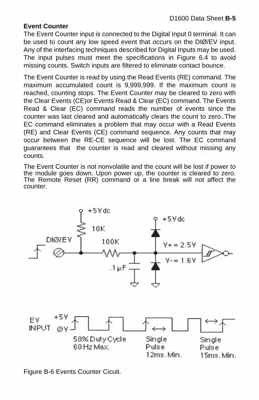
D1600 Data Sheet B-5Event CounterThe Event Counter input is connected to the Digital Input 0 terminal. It canbe used to count any low speed event that occurs on the DIØ/EV input.Any of the interfacing techniques described for Digital Inputs may be used.The input pulses must meet the specifications in Figure 6.4 to avoidmissing counts. Switch inputs are filtered to eliminate contact bounce.
The Event Counter is read by using the Read Events (RE) command. Themaximum accumulated count is 9,999,999. If the maximum count isreached, counting stops. The Event Counter may be cleared to zero withthe Clear Events (CE)or Events Read & Clear (EC) command. The EventsRead & Clear (EC) command reads the number of events since thecounter was last cleared and automatically clears the count to zero..TheEC command eliminates a problem that may occur with a Read Events(RE) and Clear Events (CE) command sequence. Any counts that mayoccur between the RE-CE sequence will be lost. The EC commandguarantees that the counter is read and cleared without missing anycounts.
The Event Counter is not nonvolatile and the count will be lost if power tothe module goes down. Upon power up, the counter is cleared to zero.The Remote Reset (RR) command or a line break will not affect thecounter.
Figure B-6 Events Counter Cicuit.

B-6 D1000 USERS MANUAL
R Vswitching
± Vhysteresis
Open 2.5V ± 0.5VØΩ 1.7V ± 5mV
For Vhysteresis
>5mV and
<0.5V: 34 V
hysteresis
R (in KΩ) =
0.5 -Vhysteresis
Vswiching
= 2.5 -
14
17 + R
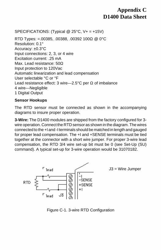
SPECIFICATIONS: (Typical @ 25°C, V+ = +15V)
RTD Types: =.00385, .00388, .00392 100Ω @ 0°CResolution: 0.1°Accuracy: ±0.3°CInput connections: 2, 3, or 4 wireExcitation current: .25 mAMax. Lead resistance: 50ΩInput protection to 120VacAutomatic linearization and lead compensationUser selectable °C or °FLead resistance effect: 3 wire—2.5°C per Ω of imbalance4 wire—Negligible1 Digital Output
Sensor Hookups
The RTD sensor must be connected as shown in the accompanyingdiagrams to insure proper operation.
3-Wire: The D1400 modules are shipped from the factory configured for 3-wire operation. Connect the RTD sensor as shown in the diagram. The wiresconnected to the +I and -I terminals should be matched in length and gaugedfor proper lead compensation. The +I and +SENSE terminals must be tiedtogether at the connector with a short wire jumper. For proper 3-wire leadcompensation, the RTD 3/4 wire set-up bit must be 0 (see Set-Up (SU)command). A typical set-up for 3-wire operation would be 31070182.
Appendix CD1400 Data Sheet
J3 = Wire Jumper
Figure C-1. 3-wire RTD Configuration
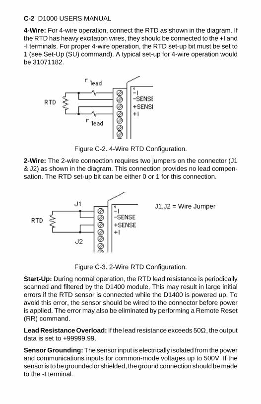
C-2 D1000 USERS MANUAL
4-Wire: For 4-wire operation, connect the RTD as shown in the diagram. Ifthe RTD has heavy excitation wires, they should be connected to the +I and-I terminals. For proper 4-wire operation, the RTD set-up bit must be set to1 (see Set-Up (SU) command). A typical set-up for 4-wire operation wouldbe 31071182.
Figure C-2. 4-Wire RTD Configuration.
2-Wire: The 2-wire connection requires two jumpers on the connector (J1& J2) as shown in the diagram. This connection provides no lead compen-sation. The RTD set-up bit can be either 0 or 1 for this connection.
J1,J2 = Wire Jumper
Figure C-3. 2-Wire RTD Configuration.
Start-Up: During normal operation, the RTD lead resistance is periodicallyscanned and filtered by the D1400 module. This may result in large initialerrors if the RTD sensor is connected while the D1400 is powered up. Toavoid this error, the sensor should be wired to the connector before poweris applied. The error may also be eliminated by performing a Remote Reset(RR) command.
Lead Resistance Overload: If the lead resistance exceeds 50Ω, the outputdata is set to +99999.99.
Sensor Grounding: The sensor input is electrically isolated from the powerand communications inputs for common-mode voltages up to 500V. If thesensor is to be grounded or shielded, the ground connection should be madeto the -I terminal.
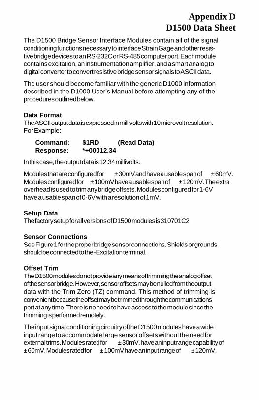
Appendix DD1500 Data Sheet
The D1500 Bridge Sensor Interface Modules contain all of the signalconditioning functions necessary to interface Strain Gage and other resis-tive bridge devices to an RS-232C or RS-485 computer port. Each modulecontains excitation, an instrumentation amplifier, and a smart analog todigital converter to convert resistive bridge sensor signals to ASCII data.
The user should become familiar with the generic D1000 informationdescribed in the D1000 User’s Manual before attempting any of theprocedures outlined below.
Data FormatThe ASCII output data is expressed in millivolts with 10 microvolt resolution.For Example:
Command: $1RD (Read Data)Response: *+00012.34
In this case, the output data is 12.34 millivolts.
Modules that are configured for ±30mV and have a usable span of ±60mV.Modules configured for ±100mV have a usable span of ±120mV. The extraoverhead is used to trim any bridge offsets. Modules configured for 1-6Vhave a usable span of 0-6V with a resolution of 1mV.
Setup DataThe factory setup for all versions of D1500 modules is 310701C2
Sensor ConnectionsSee Figure 1 for the proper bridge sensor connections. Shields or groundsshould be connected to the -Excitation terminal.
Offset TrimThe D1500 modules do not provide any means of trimming the analog offsetof the sensor bridge. However, sensor offsets may be nulled from the outputdata with the Trim Zero (TZ) command. This method of trimming isconvenient because the offset may be trimmed through the communicationsport at any time. There is no need to have access to the module since thetrimming is performed remotely.
The input signal conditioning circuitry of the D1500 modules have a wideinput range to accommodate large sensor offsets without the need forexternal trims. Modules rated for ±30mV. have an input range capability of±60mV. Modules rated for ±100mV have an input range of ±120mV.
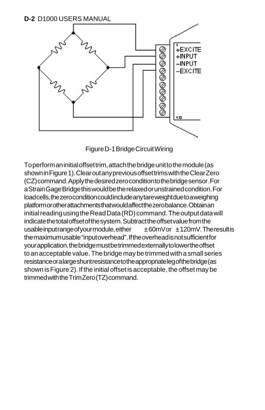
D-2 D1000 USERS MANUAL
Figure D-1 Bridge Circuit Wiring
To perform an initial offset trim, attach the bridge unit to the module (asshown in Figure 1). Clear out any previous offset trims with the Clear Zero(CZ) command. Apply the desired zero condition to the bridge sensor. Fora Strain Gage Bridge this would be the relaxed or unstrained condition. Forload cells, the zero condition could include any tare weight due to a weighingplatform or other attachments that would affect the zero balance. Obtain aninitial reading using the Read Data (RD) command. The output data willindicate the total offset of the system. Subtract the offset value from theusable input range of your module, either ±60mV or ±120mV. The result isthe maximum usable “input overhead”. If the overhead is not sufficient foryour application, the bridge must be trimmed externally to lower the offsetto an acceptable value. The bridge may be trimmed with a small seriesresistance or a large shunt resistance to the appropriate leg of the bridge (asshown is Figure 2). If the initial offset is acceptable, the offset may betrimmed with the Trim Zero (TZ) command.
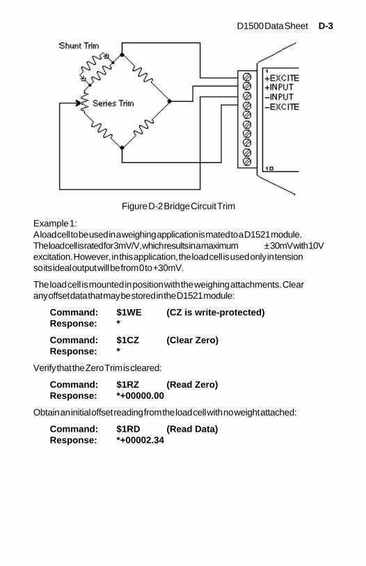
D1500 Data Sheet D-3
Example 1:A load cell to be used in a weighing application is mated to a D1521 module.The load cell is rated for 3mV/V, which results in a maximum ±30mV with 10Vexcitation. However, in this application, the load cell is used only in tensionso its ideal output will be from 0 to +30mV.
The load cell is mounted in position with the weighing attachments. Clearany offset data that may be stored in the D1521 module:
Command: $1WE (CZ is write-protected)Response: *
Command: $1CZ (Clear Zero)Response: *
Verify that the Zero Trim is cleared:
Command: $1RZ (Read Zero)Response: *+00000.00
Obtain an initial offset reading from the load cell with no weight attached:
Command: $1RD (Read Data)Response: *+00002.34
Figure D-2 Bridge Circuit Trim
D-4 D1000 USERS MANUAL
The initial offset is +2.34mV. The D1521 has a useful input range of ±60mV.After subtracting the offset the “input overhead” is -62.34mV and +57.66mV.The expected 0 to +30mV output of the load cell easily falls within theoverhead range and no external trimming is necessary.
To Trim Zero:
Command: $1WE (TZ is write protected)Response: *
Command: $1TZ+00000.00 (zero output)Response: *
Now read the data output to verify the trim:
Command: $1RD (Read Data)Response: *+00000.00
The load cell system has been trimmed to zero.
Example 2:A strain gage bridge will be used to measure both compression and tensilestrains on a structural member. The bridge is attached to a D1521 moduleand the ideal output from the bridge is ±30mV full scale.
Clear the Zero Trim:
Command: $1WEResponse: *
Command: $1CZ (Clear Zero)Response: *
Measure the initial offset from the bridge:
Command: $1RDResponse: *-00043.21
In this case, the bridge exhibits a large initial offset of -43.21mV. Subtract thisvalue from the ±60mV useful range of the D1521 to obtain and “inputoverhead” value of -16.79mV to 103.21mV. In this case the -16.79mVoverhead is not large enough to cover the -30mV that may be obtained fromthe bridge. The bridge must be trimmed externally to bring the offset to within±30mV. It is not necessary to obtain an exact zero with the external trim.
After the external trim has been performed, check the offset:
Command: $1RDResponse: *-00022.22
D1500 Data Sheet D-5
This value is within the ±30mV offset necessary to provide enough head-room for the strain gage bridge.
Trim out the remaining offset with the Trim Zero (TZ) command:
Command: $1WEResponse: *
Command: $1TZ+00000.00Response: *
The bridge is now trimmed to zero. Verify:
Command: $1RDResponse: * +00000.00
The Trim Zero (TZ) command may be used at any time to balance out offsetsdue to temperature, residual stress, tare, etc.
ExcitationD1500 modules may be ordered with either 5V or 10V excitation. Maximumexcitation current available is 60mA. Modules with 10V excitation may beused with bridges that have input impedances of 166 ohms or greater. Half-bridges of 120 Ω strain gages may be used with 10V excitation if the bridgeis completed with 350 Ω resistors. Modules with 5V excitation will sourcebridges of 85 Ω and up.
The actual excitation voltage may vary ±0.5V from the nominal values of+10V and +5V. However, the module’s internal microprocessor constantlymonitors the actual excitation voltage and provides compensation for anydeviation from the nominal value. This results in a constant data output fora constant bridge load even if the excitation changes. From a user’s pointof view, the excitation voltage will appear to be exactly +10V or +5V.
CalibrationSince the D1500 modules use a ratiometric technique to compensate forvariances in the excitation voltage, special consideration is required toproperly calibrate the unit. Figure 3 shows the calibration setup. The DigitalVoltmeter (DVM) must be capable of measuring the excitation voltage to 4digit accuracy. The voltage source must be able to provide millivolt signalsaccurate to ±5 microvolts. The resistive divider may be constructed from 1%resistors of equal value from 100 to 1000 Ω. The resistor divider places thevoltage source in the center of the common-mode range of the inputamplifier for best accuracy.
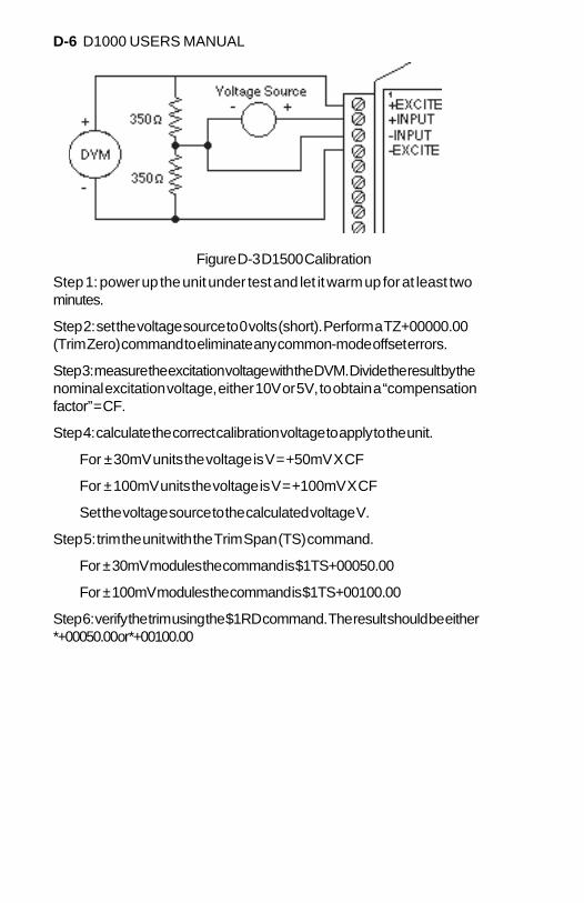
D-6 D1000 USERS MANUAL
Step 1: power up the unit under test and let it warm up for at least twominutes.
Step 2: set the voltage source to 0 volts (short). Perform a TZ+00000.00(Trim Zero) command to eliminate any common-mode offset errors.
Step 3: measure the excitation voltage with the DVM. Divide the result by thenominal excitation voltage, either 10V or 5V, to obtain a “compensationfactor” = CF.
Step 4: calculate the correct calibration voltage to apply to the unit.
For ±30mV units the voltage is V = +50mV X CF
For ±100mV units the voltage is V = +100mV X CF
Set the voltage source to the calculated voltage V.
Step 5: trim the unit with the Trim Span (TS) command.
For ±30mV modules the command is $1TS+00050.00
For ±100mV modules the command is $1TS+00100.00
Step 6: verify the trim using the $1RD command. The result should be either*+00050.00 or *+00100.00
Figure D-3 D1500 Calibration
D1500 Data Sheet D-7
Calibration Example:
We wish to calibrate a D1511 module. This unit contains 5V excitation anda ±30mV input.
Step 1 is straightforward and needs no further explanation.
Step 2: set the voltage source to 0 volts. Trim zero:
Command: $1WEResponse: *
Command: $1TZ+00000.00Response: *
Step 3: measure the excitation voltage with the DVM. In this example themeasured voltage is 4.954V Calculate the “compensation factor”:
CF = 4.954 / 5 = 0.9908
Step 4: calculate the calibration voltage:
V = +50mV X 0.9908 = +49.54mV.
Set the voltage standard to +49.54mV.
Step 5: perform the Trim Span command:
Command: $1WEResponse: *
Command: $1TS+00050.00Response: *
Step 6: verify the calibration, continuing to apply +49.54mV to the input:
Command: $1RDResponse: *+00050.00
The span trim is now complete. The Trim Zero (TZ) command may be usedto trim sensor offsets without affecting the span trim.
OptionsAll D1500 units come standard with a Digital Output /Low Alarm output. Thisconnector pin may be factory configured for a Digital Input /Event Counterinput. Consult factory.
Continuous OutputAny of the D1000 sensor input modules may be factory configured to providecontinuous output data without interrogation from the host. This option isideal for use with LED display panels to provide a continuous visual output.

D-8 D1000 USERS MANUAL
To specify continuous output, add a “C” suffix to the model number; D1511Cfor example.
Programmable ScalingThe D2500 series of interface modules are bridge units similar to the D1500series except that the input/output transfer function may be programmed bythe user. Output data may be scaled to any desired engineering units suchas pounds, psi, Newtons, etc. Nonlinear functions may also be programmedinto the module. All scaling data is stored in nonvolatile memory and may bereprogrammed any number of times. Call factory for details.
Bridge Completion Resistors
For convenience, standard bridge completion resistors may be obtainedfrom the factory. Standard values available are 120 Ω and 350 Ω.
The D2000 series is an enhancement of the D1000 series. As shipped fromthe factory, the D2000 modules operate in the same manner as their D1000counterparts. For example, a D2111 shipped from the factory contains thesame transfer function as a D1111 module; in this case they are both ±100mV inputs and communicate with RS-232C.
Before any attempt is made to program a D2000, you must first befamiliar with the operation of a D1000 module as described in thismanual. That is why you received both the D1000 manual and theD2000 programming manual with your purchase of the D2000. Pleaserefer to Chapter 1 "Getting Started" of this manual.
The D2000 series hardware is similar to the D1000 series in every respectexcept that the D2000 contains built-in commands to create custom input-to-output transfer functions. All programming is performed through thecommunications port of the D2000 module. There is never any need to openthe module case. Modules may be re-ranged remotely as many times asdesired. Function data is stored in nonvolatile memory to retain the scalingeven if power is removed.
Appendix ED2000 Series

E-2 D1000 USERS MANUAL
Appendix FD1000/2000 Continuous Operation
All D1000/2000 computer interface modules may be factory-configured toprovide continuous output of analog input data. A D1000/2000 continuousmodule is intended for applications where no host computer is present. Thelimitation to the continuous mode is that only one module can be on thecommunications line.
Continuous output may be ordered by adding a “C” suffix to the modelnumber. For example, a D1111 with the continuous output option may beordered by specifying model number D1111C.
Interfaces with the “C” option have one connector pin labeled CONT*. Thisinput pin is used to activate the continuous mode. The “*” in CONT* labelindicates that the signal is active low. The CONT* signal is pulled upinternally in the module and is voltage protected up to ±30Vdc.
If the CONT* line is left open or pulled high (>3.5Vdc), the module willoperate normally as described in the manual. The only change is that theCONT* input occupies a pin normally used for a digital input or output.
If the CONT* input is pulled low or shorted to GND, the module willcontinuously output the analog input data. The data output is transmitted inthe “short form” response format. For example, a typical output would looklike *+00100.00. Each data message starts with an asterisk (*) and isterminated with a carriage return. Communication delays and line feeds maybe added if necessary using the Set Up Command (see manual).
When the CONT* input is held low, the module will not respond to any inputcommands. Usually this is not a problem since in most cases a continuous-output module is used in a dedicated output-only application. If it isnecessary to send commands to the module, some means of switching theCONT* line must be employed. This may be in the form of a simple toggleswitch between the CONT* line and GND. The switch may be located localto the module or a dedicated wire may be run from the module to the host.
If a module with RS-232 communications is used with a host computer, thecontinuous mode may be controlled by running a wire from the CONT* pinto an RS-232 control signal, such as Request To Send (RTS). The RTSsignal may be turned on and off by the computer to select continuous ornormal mode. The CONT* input will handle the RS-232 voltage levels sinceit is protected to ±30Vdc.
F-2 D1000 USERS MANUAL
For dedicated output-only applications the RECEIVE input of RS-232modules serves no purpose and may be disconnected to eliminate one wireconnection to the host. In this case, be sure to connect the RECEIVE inputto GND to prevent a line break condition.
In continuous mode, a module will output data after every A/D conversion,or approximately eight times a second. For baud rates of 300 and 600, therepetition rate is limited by the time required for communications.
When using higher baud rates, you may notice a slight pause in the dataoutput after every 15 conversions. This pause is created when the moduleperforms an internal auto-calibration cycle and is part of normal operation.
Setup with computerThe first issue before configuring the modules is to determine theapplication baud rate. This is the data rate for communicating informationfrom the analog input module to the analog output module. This value isnormally governed by the modems being used or the length of cable inhard-wired systems. Some modems communicate at many baud rateswhile others are limited to one or two baud rate values. Hard-wiredsystems that run over long distance should consider baud rates of 9600baud or less. Remember, only eight new readings will be transmittedfrom the analog input module in one second and those readings will betransmitted about once every 125 milliseconds. Therefore, the highestbaud rates are not really necessary.
Once baud rate is determined, the modules can be properly configured.In most cases, the majority of other pre-installed factory settings in boththe analog input and output module will work “as is”. The Baud Rate isthe only parameter that must be changed in the analog input module.The Baud Rate and “Continuous Enabled” bit must be changed in theanalog output module.
Step1. The S1000 utility software is the best way to alter the setupmessage in each module. This program will run on any personal com-puter that is DOS compatible. The configuration process for both mod-ules should take about 10 minutes after all wiring connections have beenmade.
Connect the analog input module to a computer serial port (either COM1:or COM2:) using the “Figure 1.1 RS-232C Quick Hook-Up” drawing inChapter 1 of this users manual. Note that a power supply is also re-quired. Once the connections are made turn the power supply on and
Continuous Operation F-3
execute the S1000 utility software (filename = 100030.exe). At the mainmenu, select HOST and specify the correct serial computer port. Allremaining host values should not have to be changed. Press <ESC> keyand return to main menu when port selection is complete.
Step 2. Select main menu “SETUP” and enter a module address andmodel number. If the module “DEFAULT*” pin is grounded (connected toGND terminal) then enter address “1” and press <ENTER>. Enter thecorrect model number located on the module label and press <ENTER>.The module setup information will then be read and displayed for editing.
The Baud Rate value is the only value that must change in most cases.With the mouse pointer, double-click on the Baud Rate box and incre-ment to the desired value. Press the “+” key to increment the value if amouse is not available. After the value has been changed, depress the<F10> function key to download the new setup value. Press “N” not toreset the remote device. The analog input module is now configured.
Press the <ESC> key and return to the main menu. Turn the modulepower supply off and remove the black screw terminal plug from the sideof the analog input module.
Step 3. Plug the screw terminal plug, that is connected to the computer,into the side of the analog output module and turn the power supply on.Select main menu “SETUP” and re-enter the address and new modelnumber. If the “DEFAULT*” pin is grounded, enter address “1” and press<ENTER>. Enter the analog output module model number and press<ENTER>.
The Baud Rate value and “Continuous Enabled” bit are the only valuesthat must change in most cases. With the mouse pointer, double-click onthe Baud Rate box and increment to the desired value. Double-click onthe “Continuous Input” selection box to “enable” that option. Press the “+”key to increment either value if a mouse is not available. After the valueshave been changed, depress the <F10> function key to download thenew values. Press “N” not to reset the remote device.
The analog output module is now configured. Press the <ESC> key andreturn to the main menu. Turn the module power supply off and removethe black screw terminal plug from the side of the analog output module.Both modules are now properly configured.
F-4 D1000 USERS MANUALInstall/Test the configurationThe module setup modifications are complete. Both modules may nowbe bench tested or installed into the final application. The module powersupply and communications connections should be straight forwardduring installation.
Make sure that the “DEFAULT*” pin on each module IS NOT connectedto ground. For proper “continuous” operation, another pin on eachmodule MUST BE connected to ground. The “CONT*” pin on the analoginput module and the “DI2” pin on the analog output module must bothbe connected to ground (GND pin).
Turn the power supplies on for both modules, apply an test or real signalinput into the analog input module and some corresponding signal levelshould be output from the output module.
The analog output module is now configured. Press the <ESC> key andreturn to the main menu. Turn the module power supply off and removethe black screw terminal plug from the side of the analog output module.Both modules are now properly configured.
Install/Test the configurationThe module setup modifications are complete. Both modules may nowbe bench tested or installed into the final application. The module powersupply and communications connections should be straight forwardduring installation.
Make sure that the “DEFAULT*” pin on each module IS NOT connectedto ground. For proper “continuous” operation, another pin on eachmodule MUST BE connected to ground. The “CONT*” pin on the analoginput module and the “DI2” pin on the analog output module must bothbe connected to ground (GND pin).
Turn the power supplies on for both modules, apply an test or real signalinput into the analog input module and some corresponding signal levelshould be output from the output module.

WARRANTY/DISCLAIMEROMEGA ENGINEERING, INC. warrants this unit to be free of defects in materials andworkmanship for a period of 13 months from date of purchase. OMEGA’s WARRANTY adds anadditional one (1) month grace period to the normal one (1) year product warranty to coverhandling and shipping time. This ensures that OMEGA’s customers receive maximumcoverage on each product.
If the unit malfunctions, it must be returned to the factory for evaluation. OMEGA’s CustomerService Department will issue an Authorized Return (AR) number immediately upon phone orwritten request. Upon examination by OMEGA, if the unit is found to be defective, it will berepaired or replaced at no charge. OMEGA’s WARRANTY does not apply to defects resultingfrom any action of the purchaser, including but not limited to mishandling, improper interfacing,operation outside of design limits, improper repair, or unauthorized modification. This WARRANTY is VOID if the unit shows evidence of having been tampered with or shows evidenceof having been damaged as a result of excessive corrosion; or current, heat, moisture or vibra-tion; improper specification; misapplication; misuse or other operating conditions outside ofOMEGA’s control. Components in which wear is not warranted, include but are not limited tocontact points, fuses, and triacs.
OMEGA is pleased to offer suggestions on the use of its various products. However, OMEGA neither assumes responsibility for any omissions or errors nor assumes liabilityfor any damages that result from the use of its products in accordance with informationprovided by OMEGA, either verbal or written. OMEGA warrants only that the parts manufactured by the company will be as specified and free of defects. OMEGA MAKESNO OTHER WARRANTIES OR REPRESENTATIONS OF ANY KIND WHATSOEVER,EXPRESSED OR IMPLIED, EXCEPT THAT OF TITLE, AND ALL IMPLIED WARRANTIESINCLUDING ANY WARRANTY OF MERCHANTABILITY AND FITNESS FOR A PARTICULARPURPOSE ARE HEREBY DISCLAIMED. LIMITATION OF LIABILITY: The remedies of pur-chaser set forth herein are exclusive, and the total liability of OMEGA with respect to thisorder, whether based on contract, warranty, negligence, indemnification, strict liability orotherwise, shall not exceed the purchase price of the component upon which liability isbased. In no event shall OMEGA be liable for consequential, incidental or special damages.
CONDITIONS: Equipment sold by OMEGA is not intended to be used, nor shall it be used: (1) asa “Basic Component” under 10 CFR 21 (NRC), used in or with any nuclear installation or activity;or (2) in medical applications or used on humans. Should any Product(s) be used in or with anynuclear installation or activity, medical application, used on humans, or misused in any way,OMEGA assumes no responsibility as set forth in our basic WARRANTY/DISCLAIMER language,and, additionally, purchaser will indemnify OMEGA and hold OMEGA harmless from any liabilityor damage whatsoever arising out of the use of the Product(s) in such a manner.
RETURN REQUESTS/INQUIRIESDirect all warranty and repair requests/inquiries to the OMEGA Customer Service Department.BEFORE RETURNING ANY PRODUCT(S) TO OMEGA, PURCHASER MUST OBTAIN ANAUTHORIZED RETURN (AR) NUMBER FROM OMEGA’S CUSTOMER SERVICE DEPARTMENT(IN ORDER TO AVOID PROCESSING DELAYS). The assigned AR number should then bemarked on the outside of the return package and on any correspondence.The purchaser is responsible for shipping charges, freight, insurance and proper packaging toprevent breakage in transit.
FOR WARRANTY RETURNS, please havethe following information available BEFORE contacting OMEGA:1. Purchase Order number under which
the product was PURCHASED,2. Model and serial number of the product
under warranty, and3. Repair instructions and/or specific
problems relative to the product.
FOR NON-WARRANTY REPAIRS, consultOMEGA for current repair charges. Have thefollowing information available BEFORE contacting OMEGA:1. Purchase Order number to cover the
COST of the repair,2. Model and serial number of the
product, and3. Repair instructions and/or specific problems
relative to the product.OMEGA’s policy is to make running changes, not model changes, whenever an improvement is possible. This affords our customers the latest in technology and engineering.OMEGA is a registered trademark of OMEGA ENGINEERING, INC.© Copyright 2005 OMEGA ENGINEERING, INC. All rights reserved. This document may not be copied, photocopied,reproduced, translated, or reduced to any electronic medium or machine-readable form, in whole or in part, withoutthe prior written consent of OMEGA ENGINEERING, INC.

Where Do I Find Everything I Need for Process Measurement and Control?
OMEGA…Of Course!Shop online at omega.com
TEMPERATURE Thermocouple, RTD & Thermistor Probes, Connectors, Panels & Assemblies Wire: Thermocouple, RTD & Thermistor Calibrators & Ice Point References Recorders, Controllers & Process Monitors Infrared Pyrometers
PRESSURE, STRAIN AND FORCE Transducers & Strain Gages Load Cells & Pressure Gages Displacement Transducers Instrumentation & Accessories
FLOW/LEVEL Rotameters, Gas Mass Flowmeters & Flow Computers Air Velocity Indicators Turbine/Paddlewheel Systems Totalizers & Batch Controllers
pH/CONDUCTIVITY pH Electrodes, Testers & Accessories Benchtop/Laboratory Meters Controllers, Calibrators, Simulators & Pumps Industrial pH & Conductivity Equipment
DATA ACQUISITION Data Acquisition & Engineering Software Communications-Based Acquisition Systems Plug-in Cards for Apple, IBM & Compatibles Datalogging Systems Recorders, Printers & Plotters
HEATERS Heating Cable Cartridge & Strip Heaters Immersion & Band Heaters Flexible Heaters Laboratory Heaters
ENVIRONMENTALMONITORING AND CONTROL Metering & Control Instrumentation Refractometers Pumps & Tubing Air, Soil & Water Monitors Industrial Water & Wastewater Treatment pH, Conductivity & Dissolved Oxygen Instruments M0662/0605