Embed Size (px)
Citation preview
ON-SITE STORMWATER DETENTION
STANDARD
18 March 2021
Trim Number: 065491.2021

ON-SITE STORMWATER DETENTION STANDARD
2
1. LEGISLATIVE REQUIREMENTS Environmental Planning & Assessment Act 1979 (EP&A Act) Local Government Act 1993 (LG Act) Protection of Environment Operations Act 1997 Soil Conservation Act 1938 Local Land Services Act 2013 Fisheries Management Act 1994 Water Management Act 2000
2. PURPOSE/OBJECTIVES The purpose of this standard is to: 1. Detail the safeguards enforced by Council to ensure that stormwater runoff generated by new
developments does not adversely impact downstream properties for all storm events up to and including the 100-year ARI (1% AEP) event.
2. Ensure on-site stormwater detention systems are incorporated into the design of development to provide temporary storage of stormwater runoff from developments and restrict discharge from a development site at a rate which Council’s existing drainage system is capable of accommodating.
3. DEFINITIONS Annual exceedance probability (AEP) -The probability that a given rainfall total accumulated over a given duration will be exceeded in any one year. Applicant – Developer, contractor or owner. Average recurrence interval (ARI) - The average or expected time period between exceedances of a given rainfall total accumulated over a given duration. It is implicit in this definition that the periods between exceedances are generally random. Catchment - The land area draining to a point of interest. Council - means Liverpool City Council, being a body corporate constituted as a Council under the Local Government Act 1993 Councillors - means the individuals holding the office of a member of Liverpool City Council Council officer - means the Chief Executive Officer and staff of Council appointed by the Chief Executive Officer. Discharge – means the rate of flow of stormwater expressed in unit volume per unit time (litres per second).

ON-SITE STORMWATER DETENTION STANDARD
3
Drainage system - Comprises all components of stormwater infrastructure from the legal point of stormwater discharge to the receiving water body. It includes both constructed assets (pipes, culverts, overland flow paths, roadways, kerb and gutters) and natural assets (waterways and creeks). Flood – a relatively high flow of stormwater that has overtopped stream banks or artificial channels and/or local overland flooding associated with major drainage systems exceeding capacity and not able to convey all flow. Floodplain – an area of land subject to inundation by floods. On-site stormwater detention (OSD) – Temporary storage and controlled discharge of stormwater runoff. Overland flow - The surface flow of stormwater runoff that occurs when the volume of runoff exceeds the capacity of the piped drainage system. Runoff - The portion of rainfall that does not infiltrate into the soil, resulting in the presence of surface water. Stormwater system – comprises all components of stormwater infrastructure, both artificial and natural, whether that be above or below ground (e.g. pipes, surface flow paths, culverts, roadways, kerb and gutter).
4. STATEMENT 4.1 OSD requirement The OSD system must:
• Restrict the rate of stormwater discharge to the permissible rate of discharge for the site, for all
design storm events as specified by Council (up to and including the 100-year ARI (1% AEP) event).
• Provide sufficient storage to ensure peak flow rates at any point within the downstream drainage system do not increase as a result of the development during the design storm event, unless the downstream drainage system has been designed to accommodate an increase in stormwater discharge from the site.
• Drain within 24 hours to ensure the storage volume is available for a subsequent storm event.
The OSD system should:
• Be integrated into the architectural design of the development so that adequate storage areas are included in the initial stages of the site design.
• Be constructed with supervision by the OSD designer (or an appropriately qualified practising engineer) to ensure construction standards are achieved.

ON-SITE STORMWATER DETENTION STANDARD
4
4.2 Design objectives Key aspects of the OSD procedure are to determine the Permissible Site Discharge (PSD) and required Storage Volume (Vs) for the storage configuration adopted by the designer. The following are the main criteria required to determine the PSD and Vs.
• Site area or the site area contributing to the catchment at the discharge point (for example, where existing part site drains to the rear and part to the site frontage).
• Pre-development flows for the (5-year ARI), a medium recurrence interval (10 or 20- or 50-year ARI), and the upper value, which will be the 100-year ARI storm. The rate of stormwater runoff (both piped and overland) from the post developed site is not to exceed the rate of runoff from the pre-developed site for the relevant storm events.
• Weighted coefficient of runoff at the initial subdivision stage – information shall be obtained from Council.
• Weighted coefficient of runoff at the post development stage.
4.3 Information required with development application submission
• A survey plan prepared and signed by a registered surveyor with all levels to Australian Height Datum (AHD) and site boundaries defined by survey.
• Concept OSD design submission including pre & post development summary and catchment plan, volume calculations and stormwater drainage design plan in accordance with relevant documentation referred to in this standard to be prepared by a suitably qualified and practising Civil/Hydraulic engineer.
• Electronic copy of the DRAINS model used in the design of the OSD.
• A completed Council stormwater/OSD checklist signed by the design engineer.
• Where a site adjoins Crown land (such as a rail corridor or Sydney Water stormwater channel) and/or proposes discharge to a State owned asset, the approval of the asset owner must be obtained prior to lodgement of a Development Application (incl. S4.55 and S8.2 applications).
• Where an inter-allotment drainage easement/s is/are required, easement creation, written consent of downstream property owner/s agreeing to the easement/s, or agreement to participate in the negotiation of the easement/s must be obtained prior to lodgement of a Development Application (incl. S4.55 and S8.2 applications). Exception to this may be given at the discretion of Council’s Land Development Coordinator.

ON-SITE STORMWATER DETENTION STANDARD
5
4.3 When OSD is not required
• If the increased discharge for all storms up to and including a 100-year event can be accommodated by the existing downstream stormwater pipe or waterway system; or
• If a building addition or internal alteration is within the footprint (plan area) of the existing building; or
• For one-off developments and/or additions (e.g. roof, driveway, paving) where the proposed additional impervious area is less than 30m2. Any proposed additional area that exceeds the maximum impervious area permitted by the Council Development Control Plan for the site will require OSD. Note:
i. subsequent minor developments and/or additions will require OSD. ii. if uncertain, the designer is advised to confirm with a Council Land Development Engineer
and any area to be considered as existing impervious must be an approved structure; or
• If the subdivision of an existing development does not change the buildings or the impervious areas of the site.
• If sites are substantially inundated by flooding (this is to be confirmed by Council's Land Development Engineer), however controlled discharge for smaller storm events may still be required.
AUTHORISED BY Chief Executive Officer EFFECTIVE FROM 18 March 2021
DEPARTMENT RESPONSIBLE Development Assessment (City Economy & Growth) REVIEW DATE 18 March 2023 VERSIONS
Version Amended by Changes made Date TRIM Number
1 CEO New Standard 18 March 2021 065491.2021

ON-SITE STORMWATER DETENTION STANDARD
6
THIS STANDARD HAS BEEN DEVELOPED IN CONSULTATION WITH City Corporate (Governance and Legal Services) City Infrastructure and Environment ATTACHMENTS 1. On-Site Stormwater Detention Technical Specification.
REFERENCES Liverpool City Council Floodplain Management Plan Liverpool City Council Development Design and Construction Specifications (as amended).
ON-SITE STORMWATER DETENTION TECHNICAL SPECIFICATIONS
7
ATTACHMENT 1
ON-SITE STORMWATER DETENTION
TECHNICAL SPECIFICATIONS
Adopted: 18 March 2021
TRIM: 065491.2021

ON-SITE STORMWATER DETENTION TECHNICAL SPECIFICATIONS
8
This OSD Technical Specification shall be read in conjunction with Liverpool City Council Floodplain Management Plan.
General Requirements of the OSD 1. Gravity Drainage
Stormwater runoff shall be connected to Council's drainage system by gravity means. Mechanical means (i.e. pump) for disposal of stormwater runoff will not be permitted, with the exception being basement carparks. The acquisition of drainage easements over downstream properties will be required where direct access is not possible to Council's drainage system (i.e. street kerb and gutter, piped system or open channels and watercourses). All costs associated with the value of land and easement creation are to be borne by the developer. Inability to provide a gravity stormwater drainage system and easement to drain water in favour of the development site may prevent the granting of Development Consent. Written consent for the piping and acquisition of an easement is to be obtained from adjoining owners and provided to Council. Exceptions to acquiring an easement may be given at the discretion of Council’s Land Development Coordinator for sites that do not drain to the street, only where the following is proposed and genuine attempts at acquiring a downstream easement have failed:
i. extensions to an existing residential building ii. replacement of an existing dwelling house iii. secondary dwelling iv. dual occupancy
It will also need to be explicitly demonstrated that the stormwater drainage proposal will not adversely impact on the adjoining and downstream drainage system, properties and/or public places. If there are any known or expected inundation/safety problems along the re-diverted drainage route, the disposal of additional flows from the development will likely exacerbate these problems and this would not be supported. Written documentation of genuine attempts to obtain a drainage easement, including reasonable financial consideration, must be included for any application for exemption. If an exception is granted an alternative drainage system may be considered by Council. 2. Stormwater Drainage Concept Plan (SDCP) For developments that require construction of stormwater drainage, a SDCP shall be submitted with the Development Application demonstrating the feasibility of the proposed drainage system within the site and connection to Council's system. Early consultation between engineers and architects is required to reduce possible conflicts in the final plan. This plan shall show:
(i) Dimensions and areas of the site including all existing and proposed roof and pavement areas and the areas proposed to drain into the OSD and bypass the system;
(ii) Surface flow path treatment up to and including the 100-year Average Recurrence Interval overland flow paths (for site and upstream);
(iii) Any drainage easements required;

ON-SITE STORMWATER DETENTION TECHNICAL SPECIFICATIONS
9
(iv) Location, extent, size and type of OSD storage and method used to estimate storage required and cross-sections through each basin with approximate levels;
(v) Site constraints (e.g. location of services, existing easements, heritage orders, aesthetics, and trees). (vi) Location of discharge point and top of kerb level at these locations; (vii) The location and concept design levels of drainage pits, swales and retaining walls (if applicable); (viii) Weir location (if a drainage easement is required the weir is to correspond with the location of the
drainage easement); (ix) Site layout (including roof plan) and finished floor levels; (x) Existing and design contours at 0.1m intervals extending onto adjoining properties; (xi) Extent of upstream catchment; and (xii) The plan is to be to Australian Height Datum (AHD) and 1:100 scale.
Note: The Development Application will not be accepted without such a plan. Detailed designs and calculations together with engineering plans, will be required to be submitted with a Construction Certificate (CC) (supporting the concept upon which the Development Consent was granted), or Complying Development Certificate (CDC).
The CC or CDC will not be issued until these details are submitted to and approved by either an accredited certifier or Council. 3. Visual Impact All drainage structures and storage areas are to be designed to be visually unobtrusive and sympathetic with the environment. This requirement is necessary to help ensure that future occupants do not adjust or remove facilities for aesthetic reasons without understanding the functional impact of such actions.
Technical Requirements of the OSD System 1. OSD Storage/Discharge Requirements The OSD storage is to be designed to the storage/discharge relationship appropriate to the development type. Computations must be performed for the existing site conditions for a low recurrence interval (5-year ARI), a medium recurrence interval (10 or 20- or 50-year ARI), and the upper value, which will be the 100-year ARI storm. Times of concentration for the site are to be calculated and not assumed. The rate of stormwater runoff (both piped and overland) from the post developed site is not to exceed the rate of runoff from the pre-developed site for the above storm events. In determining the site PSD, the pre-development stormwater flow at the proposed discharge point shall be based on the actual area contributing area to the discharge point. For example, where existing part site slopes to the rear and part to the site frontage, and if the proposed discharge is to the site frontage the pre-developed catchment area to determine the flow rate is to be the portion draining to the frontage only. As much as possible, runoff from impervious site areas is to be drained into the OSD system. Any bypass areas are to be pervious, unless utilised for vehicular or pedestrian movement, however the impervious areas shall be minimised. The roof gutter and drainage system adjoining bypass areas shall be designed to convey the design stormwater flows (e.g. 1% AEP storm event) into the OSD system with no gutter overflow. Drainage systems must be analysed using a full hydrographic producing computer model. (i.e. DRAINS). Other Models may be considered however Council Engineers should be consulted prior to design of the system.

ON-SITE STORMWATER DETENTION TECHNICAL SPECIFICATIONS
10
The use of other models may delay the checking of plans if Council does not have the models. All designs submitted to Council must include an electronic copy of the DRAINS model used to design the OSD, detailed print outs of all input, together with a copy of data files on USB with submission of the completed plans. Computations based on the approximate triangular method or the rational method are not acceptable. 2. Surface Flow Paths Surface flow paths, including the provision of an emergency overflow to cater for blockage of the system or flows in excess of the design storm event (e.g. 100-year ARI) must be provided. The flow route must be capable of carrying the flows generated by a 100 year ARI storm with a freeboard of 300mm (a reduced freeboard may be considered for local overland flow paths with catchment areas less than 2ha, and to be minimum 200mm) to the adjacent habitable floor levels of the development site and adjoining properties. Development activities must not cause any adverse impact on adjoining or any other properties. This includes maintaining surface flow paths and not increasing water levels in these flow paths. Diverting flows from one catchment to another will not be permitted. 3. Runoff from Adjacent Properties Surface runoff from upstream properties shall not be allowed to enter OSD systems, or the OSD must be designed to cater for such (i.e. additional storage volume). OSD systems must not be located in overland flow paths which convey catchment flows through the site. 4. Floor and Ground Levels All habitable floor levels are to be a minimum of 300mm and garage/non-habitable floor levels to be a minimum of 150mm above the maximum design storage water surface level (or the basin/tank spillway level, whichever is higher). 5. Site Discharge and Connection to Council System The Permissible Site Discharge (PSD) is to be piped to the Council's drainage system. Piped discharge from the total site may be connected to the kerb and gutter of a Council roadway, provided that this does not exceed 20 litres per second for the 1 in 10 year ARI and total post development flows off site do not exceed pre development flows. If outlet flow is proposed to be discharge into the kerb and gutter of a Council roadway, the following applies:
i. A minimum 450mm x 450mm grated converter pit is to be constructed within the site at the front boundary of the property.
ii. Flows between the converter pit and the kerb and gutter are to be discharged using hot dipped galvanised steel box-section pipes as follows:
100 dia outlet pipe - use· 1 x 100mm x 100mm x 6mm thick 150 dia outlet pipe - use 1 x 200mm x 100 x 6mm thick 225 dia outlet pipe - use 2 x 200mm x 100mm x 6mm thick
Outlets to kerb and gutter should be at an angle no less than 45 degrees.
ON-SITE STORMWATER DETENTION TECHNICAL SPECIFICATIONS
11
Pipe junctions are to be configured for the minimum hydraulic losses. Pits are to be located at any change of direction, at the property boundary or, at Council's discretion, at the connection to its system. Where the frontage of the development exceeds 24m, Council will consider a second outlet connected to the kerb and gutter provided that there is a minimum of 12m separation between outlets and discharge does not exceed 20 litres/second for the 1 in 10 year ARI and total post development flows off site do not exceed pre development flows. 6. Discharge Control Devices and Storage Pits A high-level outlet is to be provided at the discharge control pit to cater for surcharge during major storm events. Access to the discharge control device is to be provided for inspections and maintenance of the silt trap and mesh screen, with a removable galvanised steel grate placed above the outlet and silt trap. Minimum grate openings to be:
i. 600mm x 600mm for pits up to 800mm in depth ii. 900mm x 900mm for pits greater than 800mm in depth
Additional access is required within a tank above the flap valve (when used in a HED system) and may be required for larger underground storage. Underground storage shall not be allowed without approval by Council. Essentially, the system is to be designed to minimise maintenance and ensure safety for the owner. To avoid unpleasant odours and health risks, maintenance of the OSD structure must be carried out on a regular basis and arranged by the owner. High Early Discharge (HED) or normal discharge control devices can be used. The minimum pit sizes are to be: 600 x 600 for pits up to 800mm in depth 900 x 900 for pits greater than 800mm in depth Step irons are required for pits greater than 1200mm in depth, and greater than 1m for a discharge control pit. A stainless steel or galvanised mesh screen (Maxi-mesh RH3030 or equivalent) with a minimum area of 50 times the orifice area, and fitted with a lifting handle, shall be provided between the orifice and the inlet. The screen is to be a minimum distance from the orifice equal to 1.5 times the diameter of the orifice or 200mm, whichever is the greater. The screen should be positioned so that the inflows are directed perpendicular to the screen. The orifice plate is to be a minimum 200mm x 200mm flat stainless-steel plate, 3mm thick. The orifice is to be tooled to the exact dimensions as calculated, uniform circular shape with sharp (not rounded) edges. The plate is to be 'Dyna bolted' onto the wall, epoxied and securely fixed by at least four Dyna bolts or similar, with one at each corner. The orifice is to be centrally located over the outlet pipe. For safety, all maintenance access to storage must conform to the current Confined Spaces Regulations, and only persons with Confined Space training shall be permitted to enter below ground storage tanks for any required maintenance. Venting shall be provided where there is potential for gas build up. A hydrostatic valve is to be provided where necessary.

ON-SITE STORMWATER DETENTION TECHNICAL SPECIFICATIONS
12
Step irons are to be installed where the depth of the underground tank is 1200mm or greater. Generally, an orifice diameter smaller than 25mm will not be approved. 7. Surface Storage Systems This specification has been framed to allow the designer maximum flexibility when integrating the storage in the site layout. The minimum design requirements for surface storage are as follows: Landscape storage
• Generally, ponding depth shall not exceed 300mm, however up to 600mm can be considered subject to Council approval. Any ponding depths greater than 600mm will require pool safe fencing surrounding the proposed ponded area and Council Engineer’s approval.
• Storage volumes in landscaping areas shall include an allowance for 20 percent additional storage for vegetation growth and construction inaccuracies.
• The desirable minimum surface slope is 1.5 percent, with the absolute minimum being 1.0 percent.
• Maximum batter slopes shall be 1:4.
• Subsoil drainage around above ground storage areas and the outlet shall be provided to prevent the ground becoming saturated during prolonged wet weather.
• Where the storage is located in an area where frequent ponding could create maintenance problems or personal inconvenience to property owners (such as courtyard areas), the first 10-20 percent of the storage should be provided in an area able to tolerate frequent inundation. For example, a paved outdoor entertainment area, or a rock garden or below ground tank can be used.
• The structural adequacy of any retaining walls, including the hydrostatic loads caused by a full storage should be checked and certified by a suitably qualified Engineer. Walls used in storage should be watertight and continuous.
Driveway and car park storage
• To avoid damage to vehicles, depths of ponding on driveways and car parks shall not be greater than 200mm.
• Transverse paving slopes within storage areas should not be less than 0.5 percent.
• Where the storage is to be provided in a commonly used area where ponding will cause inconvenience (e.g. a car park), the area should only flood about once every year on average. This will require approximately the first 15 percent of the storage to be provided in a non-sensitive area.
Above ground rainwater tank storage
• Can be considered only for secondary, single and multi-dwelling (e.g. Townhouse, villa) residential developments.
• Orifice plates are not to be installed internally to the tank for combined RWT/OSD or similar systems.
• An inspection eye is required at the outlet, near the orifice, to allow for future maintenance and inspection purposes.
• The roof gutter and drainage system shall be designed to convey the design stormwater flows (e.g. 1% AEP storm event) into the OSD system with no gutter overflow.
• Design of the tank should make provision for a minimum storage volume to ensure that water supply is always available (if required e.g. BASIX) and OSD storage volume.
ON-SITE STORMWATER DETENTION TECHNICAL SPECIFICATIONS
13
8. Location of OSD System in Multiple Dwelling Development
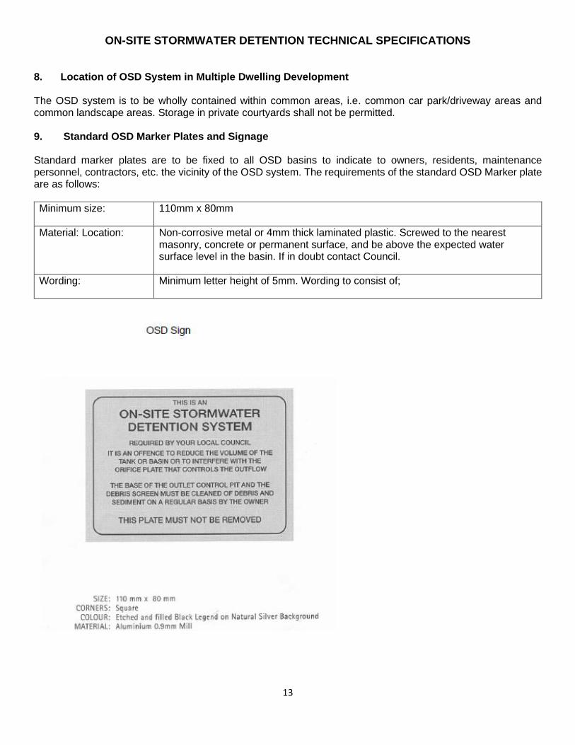
The OSD system is to be wholly contained within common areas, i.e. common car park/driveway areas and common landscape areas. Storage in private courtyards shall not be permitted. 9. Standard OSD Marker Plates and Signage
Standard marker plates are to be fixed to all OSD basins to indicate to owners, residents, maintenance personnel, contractors, etc. the vicinity of the OSD system. The requirements of the standard OSD Marker plate are as follows:
Minimum size:
110mm x 80mm
Material: Location:
Non-corrosive metal or 4mm thick laminated plastic. Screwed to the nearest masonry, concrete or permanent surface, and be above the expected water surface level in the basin. If in doubt contact Council.
Wording:
Minimum letter height of 5mm. Wording to consist of;
ON-SITE STORMWATER DETENTION TECHNICAL SPECIFICATIONS
14
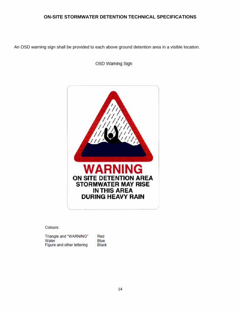
An OSD warning sign shall be provided to each above ground detention area in a visible location.
ON-SITE STORMWATER DETENTION TECHNICAL SPECIFICATIONS
15
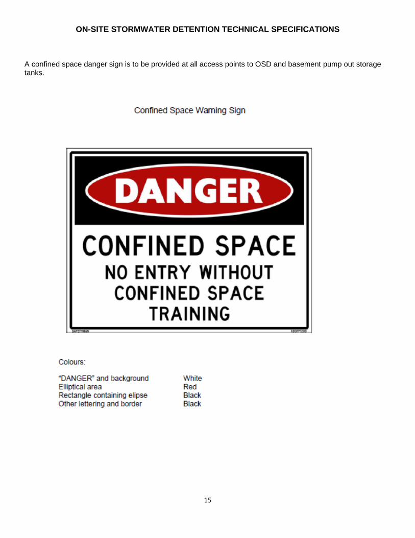
A confined space danger sign is to be provided at all access points to OSD and basement pump out storage tanks.
ON-SITE STORMWATER DETENTION TECHNICAL SPECIFICATIONS
16
Information Required for Submission 1. Details to be Submitted The following details shall be submitted with the Construction Certificate: (i) Certificates of design. (ii) Time of concentration (tc) (minutes) of existing site. (iii) The determined discharge values for the existing site and the storm duration(s) that gave these values. (iv) Dimensions and areas of the site including all existing and proposed roof and pavement areas. The areas
draining to the OSD and bypassing the system must be clearly shown. (v) Copies of certificates of title showing the creation of easements to drain water. (vi) Existing and proposed stormwater drainage layout, including pipe diameters, any existing or proposed pits,
open drains, points of discharge, detention basin(s), control pit(s), surcharge facilities and surface flow paths(s). Where connection is to be made via an easement through downstream properties, details are to be supplied.
(vii) Cross sections, dimensions (mm) and volume (m3) of the proposed detention storage. Stage/Storage calculations for the storage area.
(viii) Diameter (mm) of the orifice/outlet. Orifice calculations to be submitted. (ix) Floor levels of all permanent structures, the proposed and existing surface levels and contours, and the
drainage system to Australian Height Datum. (x) A plan, elevations and sections to show basin invert level centreline level of outlet orifice, top water level,
finished surface levels and adjacent structures. These are to show the relationship to adjoining properties. (xi) Longitudinal section of pipelines showing calculated flow, velocity, size, type and class of pipe, grade,
invert and surface levels, all service utilities and hydraulic grade line(s). (xii) The frequency and period of ponding in the above ground storage. (xiii) Details of access and maintenance facilities. (xiv) Construction and structural details of all pits, and manufacturers' specifications for proprietary products. (xv) Hydrologic and hydraulic computations. (xvi) The emergency flow path and estimated flood levels in the event of blockage or damage to the OSD
system. (xvii) Property(ies) burdened by the OSD system. Where WSUD components are proposed, calculations and details of both the OSD and WSUD components are required which clearly demonstrate that the designer has integrated the systems to allow for the impact of each on the design of the other. An electronic copy of the DRAINS model used to design the OSD. Calculations verifying that the overflow from the DCP to the storage, flowpaths/floodways, internal drainage systems and any overflow weirs have sufficient capacity. Location and extent of any floodways/flowpaths. A maintenance schedule outlining required maintenance, by who, how and when it is to be done. 2. Analysis of the External Catchment
If the outlet from the basin cannot be classed as a 'free outlet', full hydraulic calculations will be required for the receiving drainage system in order to demonstrate the effect on the proposed detention system. Hydraulic
ON-SITE STORMWATER DETENTION TECHNICAL SPECIFICATIONS
17
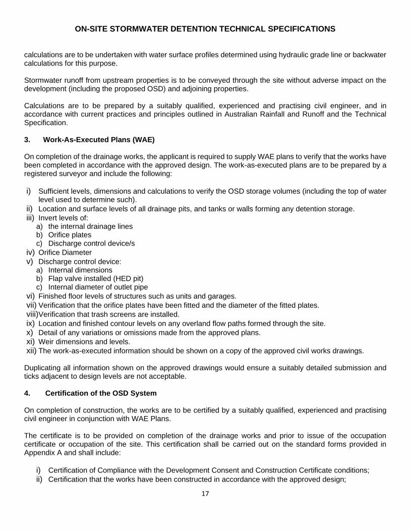
calculations are to be undertaken with water surface profiles determined using hydraulic grade line or backwater calculations for this purpose. Stormwater runoff from upstream properties is to be conveyed through the site without adverse impact on the development (including the proposed OSD) and adjoining properties. Calculations are to be prepared by a suitably qualified, experienced and practising civil engineer, and in accordance with current practices and principles outlined in Australian Rainfall and Runoff and the Technical Specification. 3. Work-As-Executed Plans (WAE) On completion of the drainage works, the applicant is required to supply WAE plans to verify that the works have been completed in accordance with the approved design. The work-as-executed plans are to be prepared by a registered surveyor and include the following:
i) Sufficient levels, dimensions and calculations to verify the OSD storage volumes (including the top of water level used to determine such).
ii) Location and surface levels of all drainage pits, and tanks or walls forming any detention storage.
iii) Invert levels of: a) the internal drainage lines b) Orifice plates c) Discharge control device/s
iv) Orifice Diameter
v) Discharge control device: a) Internal dimensions b) Flap valve installed (HED pit) c) Internal diameter of outlet pipe
vi) Finished floor levels of structures such as units and garages.
vii) Verification that the orifice plates have been fitted and the diameter of the fitted plates.
viii)Verification that trash screens are installed.
ix) Location and finished contour levels on any overland flow paths formed through the site.
x) Detail of any variations or omissions made from the approved plans.
xi) Weir dimensions and levels.
xii) The work-as-executed information should be shown on a copy of the approved civil works drawings.
Duplicating all information shown on the approved drawings would ensure a suitably detailed submission and ticks adjacent to design levels are not acceptable. 4. Certification of the OSD System On completion of construction, the works are to be certified by a suitably qualified, experienced and practising civil engineer in conjunction with WAE Plans. The certificate is to be provided on completion of the drainage works and prior to issue of the occupation certificate or occupation of the site. This certification shall be carried out on the standard forms provided in Appendix A and shall include:
i) Certification of Compliance with the Development Consent and Construction Certificate conditions;
ii) Certification that the works have been constructed in accordance with the approved design;

ON-SITE STORMWATER DETENTION TECHNICAL SPECIFICATIONS
18
iii) Certification of the structural adequacy of the storage device; and
iv) Certification of the adequacy of the OSD system;
v) Certification that any variations from the approved design will not impair the performance of the OSD system.
vi) Structural engineer’s certificate for the structural stability and soundness of the OSD basin retaining wall(s) / underground OSD tank, as water retaining structures and ensure that there are no leaks through the structure or under the footing of the retaining wall(s). The structural certificate should reference to relevant Australian standards (e.g. AS3600: Concrete structure, AS1170.1&2: Loading Code, AS3500 etc).
vii) A certificate from the licensed installer of the rainwater tank reuse and OSD system is to be provided detailing how much total volume for rainwater tank and OSD tank has been installed.
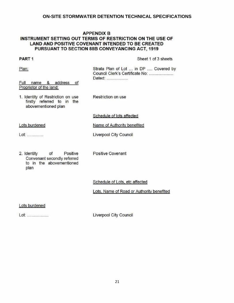
5. Legal Requirements The OSD systems are long term structures intended to control discharges from the site over the entire life of the development. A well-designed and properly constructed system can still be rendered ineffective by alterations, such as filling of the detention basin and planting of garden beds across flow path, or by poor maintenance. Therefore, it is necessary that these systems are protected and regularly maintained. This is achieved by an instrument setting out terms of restriction on use and positive covenant created pursuant to Section 88 of the Conveyancing Act, 1919. The location of the "Stormwater Detention System" shall be shown on the D. P. or included as a site plan attached to the Section 888 Instrument. Prior to the issue of the Occupation Certificate or occupation of the site, the creation of a Restriction on Use of Land and Positive Covenant over the OSD system(s) are to be registered with the Land Titles Office. Liverpool City Council shall be nominated as the body empowered with authority to release or vary the Restrictions and Covenants. Standard wording for these shall be adopted and a sample 88B Instrument has been provided in Appendix B (similar wording to be used in 88E Instruments).

ON-SITE STORMWATER DETENTION TECHNICAL SPECIFICATIONS
19

ON-SITE STORMWATER DETENTION TECHNICAL SPECIFICATIONS
20
As the copyright owner of the plans, I hereby authorize release of the approved drainage/sketch plan to future owners
of the property to assist in the maintenance of the On-site Stormwater Detention (OSD) system.
Signature: ___________________________________________ Date: _____________
Name: _______________________________________________(print)
ON-SITE STORMWATER DETENTION TECHNICAL SPECIFICATIONS
21
ON-SITE STORMWATER DETENTION TECHNICAL SPECIFICATIONS
22
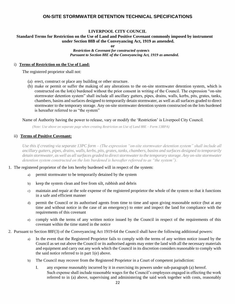
LIVERPOOL CITY COUNCIL Standard Terms for Restriction on the Use of Land and Positive Covenant commonly imposed by instrument
under Section 88B of the Conveyancing Act, 1919 as amended.
or Restriction & Covenant for constructed system/s
Pursuant to Section 88E of the Conveyancing Act, 1919 as amended.
i) Terms of Restriction on the Use of Land:
The registered proprietor shall not:
(a) erect, construct or place any building or other structure. (b) make or permit or suffer the making of any alterations to the on-site stormwater detention system, which is
constructed on the lot(s) burdened without the prior consent in writing of the Council. The expression “on-site stormwater detention system” shall include all ancillary gutters, pipes, drains, walls, kerbs, pits, grates, tanks,
chambers, basins and surfaces designed to temporarily detain stormwater, as well as all surfaces graded to direct stormwater to the temporary storage. Any on-site stormwater detention system constructed on the lots burdened
is hereafter referred to as “the system”
Name of Authority having the power to release, vary or modify the ‘Restriction’ is Liverpool City Council.
(Note: Use above on separate page when creating Restriction on Use of Land 88E – Form 13RPA)
ii) Terms of Positive Covenant:
Use this if creating via separate 13PC form – (The expression “on-site stormwater detention system” shall include all ancillary gutters, pipes, drains, walls, kerbs, pits, grates, tanks, chambers, basins and surfaces designed to temporarily detain stormwater, as well as all surfaces graded to direct stormwater to the temporary storage. Any on-site stormwater detention system constructed on the lots burdened is hereafter referred to as “the system”).
1. The registered proprietor of the lots hereby burdened will in respect of the system:
a) permit stormwater to be temporarily detained by the system
b) keep the system clean and free from silt, rubbish and debris
c) maintain and repair at the sole expense of the registered proprietor the whole of the system so that it functions in a safe and efficient manner
d) permit the Council or its authorised agents from time to time and upon giving reasonable notice (but at any time and without notice in the case of an emergency) to enter and inspect the land for compliance with the requirements of this covenant
e) comply with the terms of any written notice issued by the Council in respect of the requirements of this covenant within the time stated in the notice
2. Pursuant to Section 88F(3) of the Conveyancing Act 1919-64 the Council shall have the following additional powers:
a) In the event that the Registered Proprietor fails to comply with the terms of any written notice issued by the Council as set out above the Council or its authorised agents may enter the land with all the necessary materials and equipment and carry out any work which the Council in its discretion considers reasonable to comply with the said notice referred to in part 1(e) above.
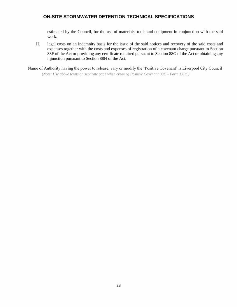
b) The Council may recover from the Registered Proprietor in a Court of competent jurisdiction:
I. any expense reasonably incurred by it in exercising its powers under sub-paragraph (a) hereof. Such expense shall include reasonable wages for the Council’s employees engaged in effecting the work referred to in (a) above, supervising and administering the said work together with costs, reasonably
ON-SITE STORMWATER DETENTION TECHNICAL SPECIFICATIONS
23
estimated by the Council, for the use of materials, tools and equipment in conjunction with the said
work.
II. legal costs on an indemnity basis for the issue of the said notices and recovery of the said costs and
expenses together with the costs and expenses of registration of a covenant charge pursuant to Section 88F of the Act or providing any certificate required pursuant to Section 88G of the Act or obtaining any injunction pursuant to Section 88H of the Act.
Name of Authority having the power to release, vary or modify the ‘Positive Covenant’ is Liverpool City Council
(Note: Use above terms on separate page when creating Positive Covenant 88E – Form 13PC)