Embed Size (px)
Citation preview
C.P. No. 1039
M I N I S T R Y O F T E C H N O L O G Y
AERONAUTICAL RESEARCH COUNCIL
CURRENT PAPERS
On the Flexure of aConical Frustum Shell
byE . H . Mansfreld, Sc.D.
.
LONDON. HER MAJESTY’S STATIONERY OFf?CE
1969
PRICE 10s 6d NET

U.D.C. 539.384 : m-4~1 : 621434.5 : 621-44.8.1 :624.078.8 : 621.007 : 629.19.012.25
C.P. N0.1039~October IV67
ON THE FLEXUFE OF A CONICAL FRUSTUM SHELL
by
E. H. Mansfield. Sc.D.
SUMMARY
This Report considers theoretically and experimentally some of theproblems associated with the flexure of two unequal cylindrical shells Joinedby a conical frustum. Particular attention is given to the determination ofthe overall flexursl stiffness of the conical frustum and to structuraldesign considerations associated with the provision of a separation capabilityin the frustum. The results are particularly relevant to the design of multi-stage rockets.
*Replaces R.A.E. Technical Report 67274 - A.R.C. 30212.
2
CONTENTS
1 INTRODUCTION2 SYMBOLS3 ANALYSIS
3.1 The unreinforced conical frustum shell with rigid ends3.2 The reinforced conical frustum shell with rigid ends3.3 The effect of non-rigid Junctions at the ends of the frustum3.4 The conical frustum shell reinforced by four stringers3.5 The conicsl frustum shell with s separation capability
4 EXF'ERIMENTS ON XYLONITR CONICAL FRUSTUM SHELLS4.1 Model dimensions
4.2 The tests4.3 Test results
5 CONCLUSIONSAppendix A Stresses in an annulsr plate at the ends of the frustumAppendix b The loads in the reinforcing rings at the ends of the
frustumAppendix C The loads in the reinforcing rings at separation linesReferences
m
3
3
5
5
7
a
II
17
21
21
22
23
24
25
27
30
32
IllustrationsDetachable abstract cards
Fig-urea I-12
3
1 INTRODUCTION. In a multi-stage rocket the structure of each stage is basicelly a
cylindrical shell. When adjacent stages differ in size they msy be Joined byL a conicel frustum shell. At the junctions of the frustum with the cylirdricd.
shells there will be stiffening rings to equilibrate the radial component ofthe direct stresses in the frustum. The provision of a separation capabilityin the frustum rnw also necessitate some internal stiffeners and/or bracing.Indeed, one of the main structural difficulties In providing such a capabilitylies in the provision of an adequate transverse shear-carrying capacity in thefrustum, even when the transverse shears applied are negligible. This is becausethe direct stresses resisting an applied moment have a transverse component dueto the taper.
.
In this report an analysis is given of the stresses In the frustum due tothe remote application of a bending moment. The analysis is kept as simple aspossible, consistent with an adequate determination of the overall flexuralstiffness of the frustum. This latter information 1s of particular value in avlbrationsl analysis, for example, where the rocket may be regarded as a beamof varying rigidity. Attention is also given to structursl design considera-tions associated with the provision of a separation capability. A simplifiedanalysis is presented for optimising the structure to achieve maximum overallflexural stiffness. In addition, a series of model conical frustum shellshave been tested to exemplify the relative merits of different types of sheerconnection across a separation line.
2 SYMBOLS
AlaA section areas of reinforcing rings
A' section areas of reinforcing rings resisting shear, i.e.approximate web area
As section area of stringer
D Et3/12(1-v2)
E Young's modulus
Fn functions of a, p, p
h depth of reinforcing ring
ZI flexural stiffness of equivalent beam of length 8
EI, flexural stiffness of cylinder with properties as at small endof frustum
4
*IIG
4
M
m
Ns*Ne*Nse
p1*p2
P s
r
s
t
%
ts
Tr'Te
U
urv
IA
a
P
Y
?
e
P
"
cr*
+I**2
flexural stiffness of reinforcing ring
shear modulus
axial length of frustum
bending moment applied to cylinders remote from frustum
bending moment in reinforcing ring
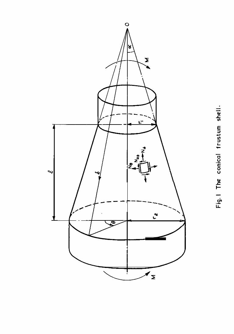
forces per unit length in the shell, see Fig.1
hoop loads in reinforcing rings
direct load in stringer
radius of frustum, see Fig.1
distance along generators of frustum from cone ape*
thickness of shell
thickness of reinforcing ring
thickness of stringer-sheet
radial and shear loads per unit length acting on reinforcingring
strain energy in frustum
strain enera in reinforcing rings
shear in reinforcing ring
width of reinforcing ring
semi-angle of frustum
r rd1introduced before equation (19)
I/I, t non-dimensional flexural stiffness of frustum
angular distance, see Fig.1
%,dtPoisson's ratio
maximum stress in smaller cylinder due to bending
parameters introduced in equation (16)
Suffices 1, 2 (except after F) refer to small and large end of frustum.
5
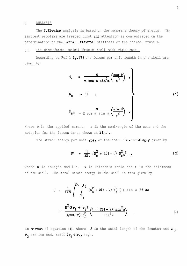
3 ANALYSIS
The fol.lowing analysis is based on the membrane theory of shells. Thesimplest problems are treated first and attention is concentrated on thedetermination of the overall flexural stiffness of the conical frustum.
3.1 The unreinforced conical frustum shell with rigid ends
According to Ref.1 (p.67) the forces per unit length in the shell aregiven by
Ne =O ,
N MSO = VI co9 a sin a '
i
where M is the applied moment, a is the semi-angle of the cone and thenotation for the forces is as shown in Fig.1.
The strain energy per unit area of the shell is accordulgly given by
where E is Young's modulus, Y is Poisson's ratio and t is the thicknessof the shell. The total strain energy in the shell is thus given by
27c s2u 1=-4 i
1% + 2(1+ v) Nie] s sin a de ds0 Sl
M2&(r, + r2) 1=2 2
Wt r, r2 (+ 2(1+ u) sin2a
3 ),
cos a
(1)
(3)
in virtue of equation (I), where 4 is the axial length of the frustum and rl,r2 are its end. radii (rl < r2, say).
6
Now the strain enera stored in a uniform beam whose flexural stiffness is EI isgiven by
2u = "& ,
so that by equating equations (3) and (4) we can determine the stiffness of anequivalent uniform beam of length 8. Furthermore, this stiffness is givenconveruently in nondxnensional terms by expressing it aa a multiple of the stiff-ness of a cylinder whose skin thickness is t and radius r,, say. In other wordswe write
where
Thus we find
I = rl1,' SBSTI
II = tir: .
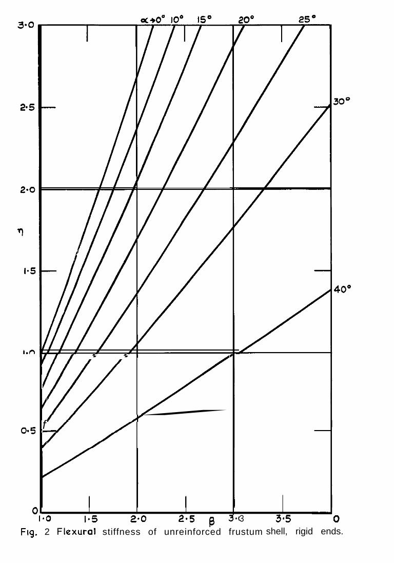
rl = F,(a) F,(P)
where
F,(a) = cos5a1 + 2(1+ v) sin*a
,
and
F2(B) = $
$ = �☺r, l
(5)
(6)
The parameter q is plotted against p for various values of a in Fig.2.[It is to be noted that as a + 0, F , +I so that F21, my be identified as the'average' overall stiffness of the frustum regarded as a beam of varying stiff-ness. Thus, had we chosen F21, instead of I, as our reference stiffness theeffect of' the & of taper would have been given simply by the term F,(a).This, in turn, is given by q as p + 1.1
The values of q determined here relate to a frustum with rigid ends;a finite rigidity of the ends results in a further drop in overell stif'fness.See section 3.3.
3.2 The reinforced conical frustum shell with rigid ends
Here we consider a shell of constant thickness reinforced by closelyspaced stringers lying along the generators of the frustum. The stringersare assumed to be continuous and untapered so that, unlike the skin, theirtotal section ares does not vary sxially. The stringers are assumed to besufficiently close for the concept of a stringer-sheet to be valid.
The forces per unit length in the reinforced shell are again given byequation (1) because they are determined entirely from equilibrium conditions.The strain enerw per unit area of the reinforced shell is, however, given by
t +8t8 +a1 + u)
U' 1
(
N2 &= E t >
,
where ts is the thickness of the equivalent stringer-sheet. Further, if
t8 = t8 1 at the smeller end of the frustum, we csn write,
wheret8 = W,/8 ,
(8)
Substitution of equations (1) and (8) into (7) and integration yields
M2e(r, + r2) F (p,~) + 2(1+ u) sin2u =
l+nEt r2 r2 (' 3 4t
1 2CO8 a
where
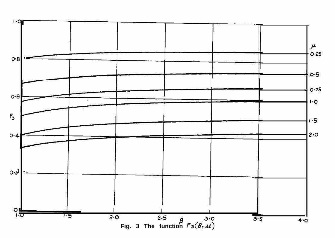
F3(P,td = 'I
(9)
which 18 plotted against a for various values of p in Fig.3.
By equating equation8 (4) and (9) we may determine the stiffness of anequivalent uniform beam. Expressing this as a multiple of the stiffness of acylinder specified by t, ts , and r, gives, in a manner analogous to,equation (5),
where
and
I = 71, 9
II = xt(l+p) r: ,
IF2(P) 3cc9 a
17 =Cl+ 1.4 IF3(B,d + 2(1+ u) sin24
.
J
(10)
For the particular case in which p = I, the parameter q is plotted against pfor various values of a in Fig.&,
3.3 The effect of non-rigid junctions at the ends of the frustum
So far the analysis has assumed that the junctions between the conicalfrustum and the cylinders are ngid. In practice, of course, this is not soand flexibility of these junctions further reduces the overall flexural stiff-ness of the conical frustum. In this section we aaaume that these Junctionsare rex-dorced by rings of radius r,, r2 and section areaa A,, A2 respectively.[It transpires that, for this particular loading condition the flexuralrigidity of the rings is not an important parameter except in 30 far as itaffects the stability of the rings.] In Appendix A a stress function solutionis presented for the case of a deep ring in the form of an annulus of constantthickness.
At a Junction there is equilibrium of the axial components of the forcesper unit length in the cylinder and frustum, and the forces acting on the ringare purely radial and shear loads. If these are denoted by T, and TO respectively,we have for the ring at s = a,,
T
Tr= Ns sin a =
(M
>ccs e
x cc9 a sin a -t251
and
Tel = Nse = Y>
sin 07t cc9 a sin a 2 .
7 I
(11)
It may be verified that these distributed forces do not cause any bending of thering but produce a varying hoop load P, given by
P, =
By the sane token the hoop load P2 is given by
The total strain energy stored in the rings is thus given by
2x r P2 2u, = &
i (u+- der2 p2*I *2 >0
l
(12)
(13)
(14)
CNe note here that in determining A,, A2 allowance may be made for the adjacentshell. skin - an 'edge effect' not accounted for by membrane theory. Theeffective section areas of skin (&A,,, &A2) are approximately the same as thosein a continuous cylindrical shell under a ring of radisl loads (see Ref.1,p.283) for which
6A1 a 1.5 r$ t3'" ,
"*2 = 1.5 rj t312 ,!
(15)
where it IS assumed that the thickness of the cylx&&xl shells adJolrung thefrustum 1s the same as that in the frustum.]
The total strain energy in the frustum is the sum of expressions (9) and(14). By equating this sum to expression (4) we can find, as before, the stli'f-ness of an equivalent beam. Representation in non-dimensional form isfacilitated by the introduction of the symbols
10
$1 = +,t ,
$2 = AJr2t ,
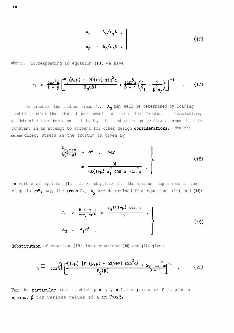
whence, corresponding to equation (IO), we have
(16)
3cos ar
3(p,p) + 2(l+u) sin2a
T =iq*2(P)
+*(*+-j-J]-' . (17)
In practice the section areas A,, A2 may well be determined by loadingconditions other than that of pure bending of the conical frustum. Nevertheless,we determine them below on that basis, but introduce an arbitrary proportionalityconstant in an attempt to account for other design considerations. Now themaximum direct stress in the frustum is given by
xt(l+p) sf cos a sin*a,J
(18)
in virtue of equation (1). If we stipulate that the maximum hoop stress in therings is @, say, the areas A,, A2 are determined from equations (12) and (13):
A, = M tan a r,t(l+p) sin a
7tr,y+ = Y t
A2 = Al/P .
(‘9)
Substltutlon of equation (19) into equations (16) and (17) gives
l+p) [F (p,p) + *(l+v) sin*4 -1q = 3cos a i’ *2(p)
+ 2-f sin2a$-I *1 (20)
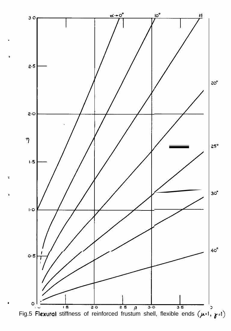
For the particular case in which j.! = 1, y = I, the parameter 7~ is plotteda&aixist p for various values of a m Flg.5.
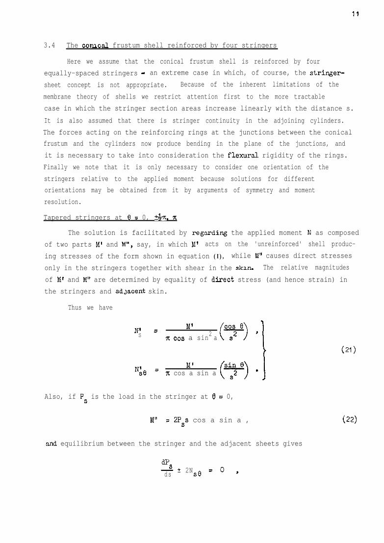
3.4 The co~csl frustum shell reinforced by four stringers
Here we assume that the conical frustum shell is reinforced by fourequally-spaced stringers - an extreme case in which, of course, the stringer-sheet concept is not appropriate. Because of the inherent limitations of themembrane theory of shells we restrict attention first to the more tractablecase in which the stringer section areas increase linearly with the distance s.It is also assumed that there is stringer continuity in the adjoining cylinders.The forces acting on the reinforcing rings at the junctions between the conicalfrustum and the cylinders now produce bending in the plane of the junctions, andit is necessary to take into consideration the flexural rigidity of the rings.Finally we note that it is only necessary to consider one orientation of thestringers relative to the applied moment because solutions for differentorientations may be obtained from it by arguments of symmetry and momentresolution.
Tapered stringers at 0 = 0, 5&t. x
The solution is facilitated by regarding the applied moment M as composedof two parts M' and M", say, in which M' acts on the 'unreinforced' shell produc-ing stresses of the form shown in equation (I), while M" causes direct stressesonly in the stringers together with shear in the skin. The relative magnitudesof Ml and M" are determined by equality of direct stress (and hence strain) inthe stringers and adJaCent skin.
Thus we have
N' = M' co9 eS 2x co9 a sin a ( >7'
i
N& = M ' sin 071 cos a sin a ()J
-.2S
Also, if Ps is the load in the stringer at 6 z 0,
M" = 2Pss cos a sin a ,
(21)
(22)
and equilibrium between the stringer and the adjacent sheets gives
dFs 5ds 2NSe so,
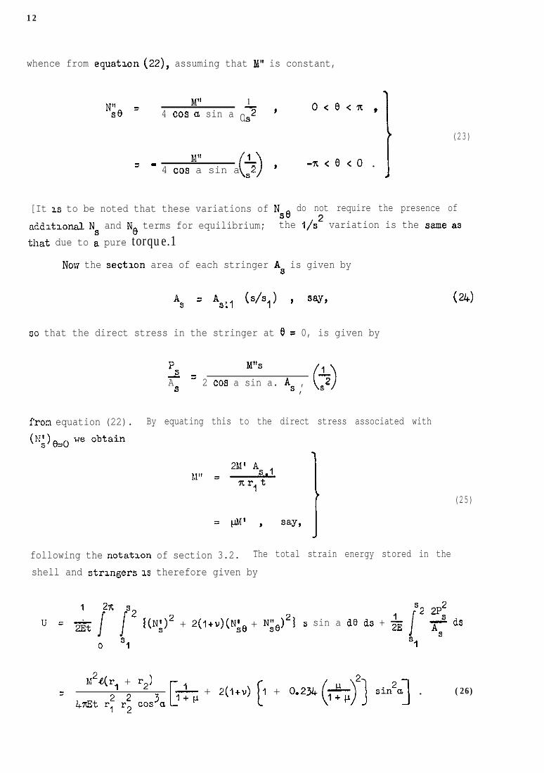
12
whence from equatmn (22), assuming that M" is constant,
N& = M" 14 cm a sin a 02 ' o<etz,
(23)
M”= - 104 cos a sin a s2 ' -n<e<o .
I
[It IS to be noted that these variations of NSe do not require the presence ofadd~tmnal Ns and Ne terms for equilibrium; the I/s2 variation is the same asthat due to a pure torque.1
Now the sectmn area of each stringer A, is given by
AS = *s1, b/s,) 9 say,
so that the direct stress in the stringer at 0 = 0, is given by
(24)
s W’SAS = 2 cm a sin a. As ,
102, s
fron equation (22). By equating this to the direct stress associated with
(25)
following the notation of section 3.2. The total strain energy stored in theshell and strmgers IS therefore given by
2n1 s2 s2 2P2U=z
IiI(N;)2 + 2(l+v)(N& + N;e)2j s sin a de ds + Y&
i-2 asAS
0 s1 9
M2&(r, + r2)7
l&t r: r; cos3a+ 2(1+v) (I + 0.2,(*7) sin2a] . (26)
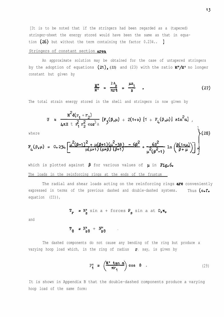
13
[It is to be noted that if the stringers had been regarded as a (tapered)stringer-sheet the energy stored would have been the same as that in equa-tion (26) but without the term containing the factor 0.234.. ]
Stringers of constant section area
An approximate solution may be obtained for the case of untapered stringersby the adoption of equations (21), (22) and (23) with the ratio W/M' no longerconstant but given by
M" 2APSI
iF=s=-.
xl-t S
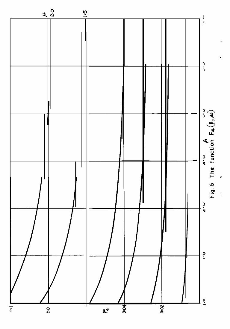
The total strain energy stored in the shell and stringers is now given by
u -M2.tT(r, + r2)
22 3l+xE t r, r2 cos a[F,(i%p) + 2(l+u) 11 + Fq(P,dI sin2d ,
1where
which is plotted against p for various values of p in Fig.6
The loads in the reinforcing rings at the ends of the frustum
The radial and shear loads acting on the reinforcing rings are convenientlyexpressed in terms of the previous dashed and double-dashed systems. Thus (c.f.equation (II)),
andTr = Nl sin a + forces Ps sin a at 0,X.,
%I = N& + N'& .
The dashed components do not cause any bending of the ring but produce avarying hoop load which, in the ring of radius r, say, is given by
P; = C';o)oos e . (29)
It is shown in Appendix B that the double-dashed components produce a varyinghoop load of the same form:
14
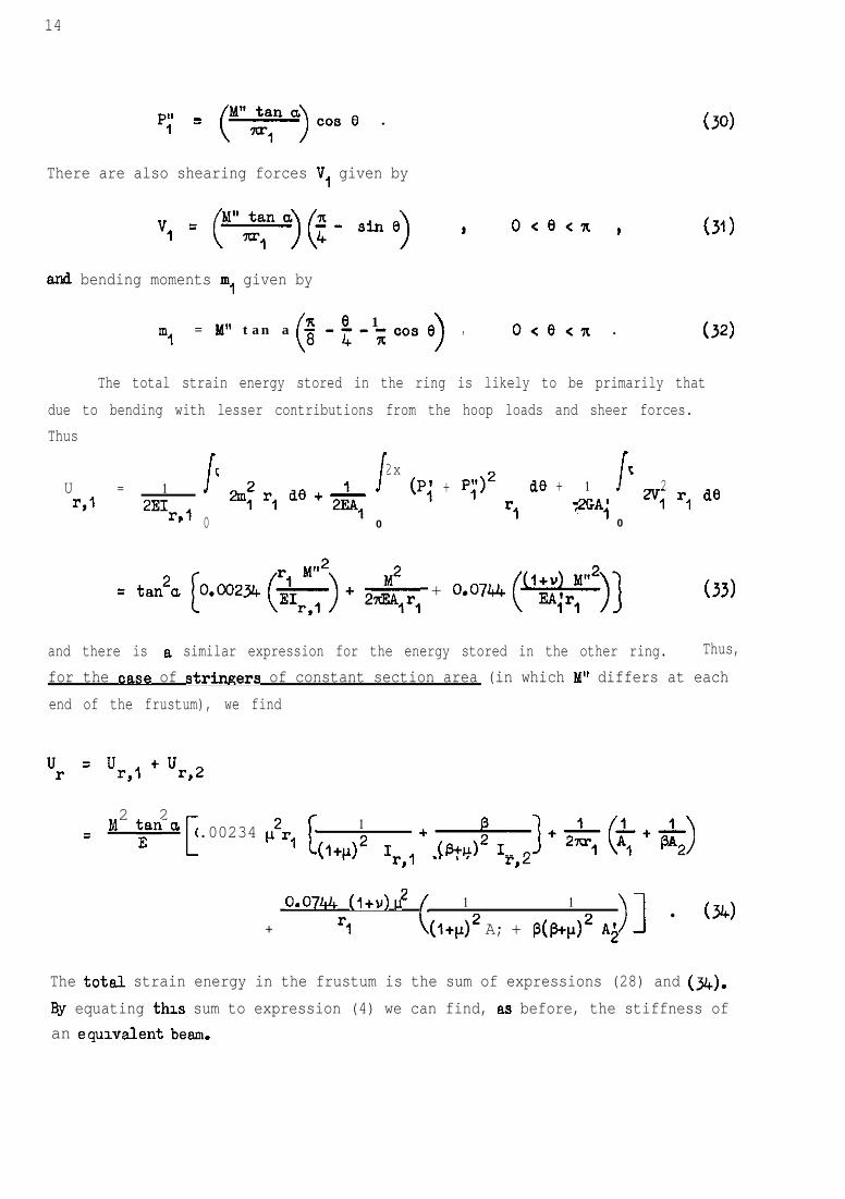
P; = (M"~a)cosO . (30)
There are also shearing forces V, given by
v, = (yy”)(~- sine) * o<e<n )
and bending moments m, given by
ml= M" tan a
(e 1; -i;-;cos e
>, o<e<n .
(31)
The total strain energy stored in the ring is likely to be primarily thatdue to bending with lesser contributions from the hoop loads and sheer forces.Thus
x 2x xU 1=,I
=2EI,,
1 1 (Pi + p;)2 1r,
de 2+
'7 2GA,
1 2vl r, de0 0 0
= tan2a C,@323Jt(&$)+ 2$,rl + O.W4(*)] (33)
and there is e similar expression for the energy stored in the other ring. Thus,for the ease of strwers of constant section area (in which M" differs at eachend of the frustum), we find
ur =u +u=,I =J
M2 2
= y a 0.00234 p2r,L- c
1
(1+d2 I=,, (a+d2 Ir,2+-)+TkJ-$++)
u
+ o*0744 (‘+v) 2 (
1
rl (I+P)~ A; +1
P(P+d2 Ai>I l (34)
The total strain energy in the frustum is the sum of expressions (28) and (344).By equating thu sum to expression (4) we can find, as before, the stiffness ofan equvalent beam.
15
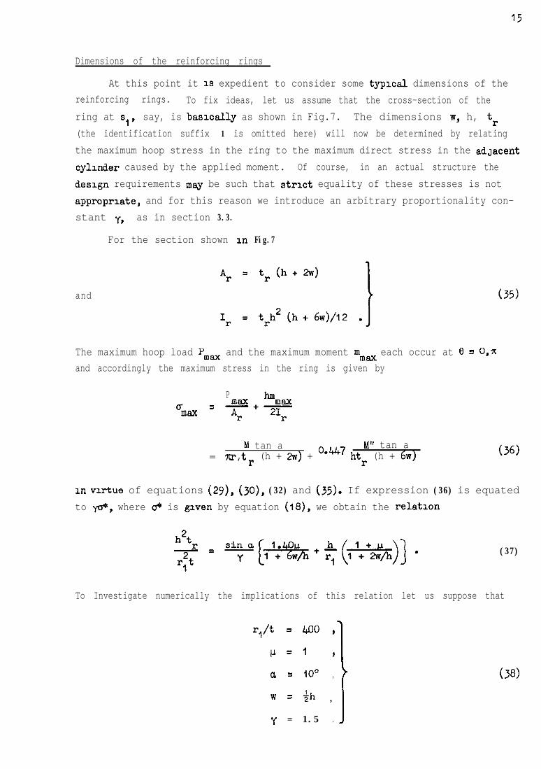
Dimensions of the reinforcing rings
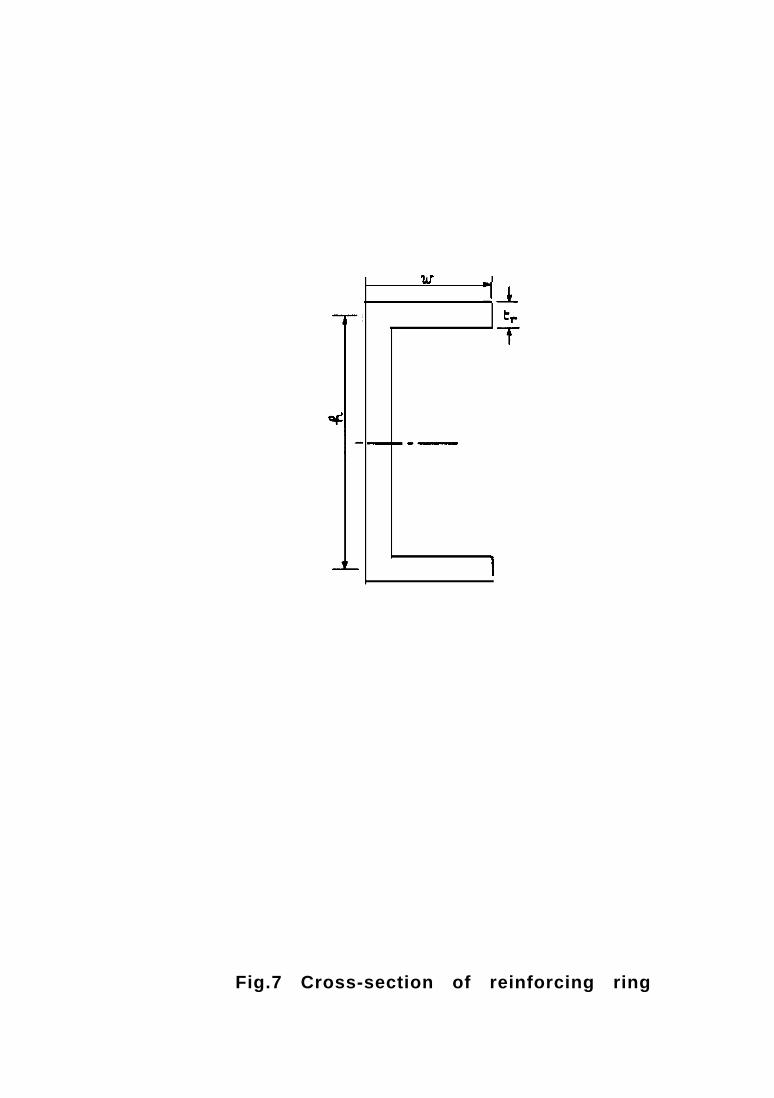
At this point it 1s expedient to consider some typlcsl dimensions of thereinforcing rings. To fix ideas, let us assume that the cross-section of thering at s,, say, is basxally as shown in Fig.7. The dimensions w, h, tr(the identification suffix 1 is omitted here) will now be determined by relatingthe maximum hoop stress in the ring to the maximum direct stress in the adJacentcylander caused by the applied moment. Of course, in an actual structure thedesign requirements msy be such that strxt equality of these stresses is notappropriate, and for this reason we introduce an arbitrary proportionality con-stant y, as in section 3.3.
For the section shown an Fig.7
and
The maximum hoop load Pm, and the maximum moment mmax each occur at 8 = 0,~and accordingly the maximum stress in the ring is given by
P hmu = max+maxmax Ar 'Ir
M tan a M" tan a= ?rrt, r (h + 2~) + o-k47 htr (h + 6~)
1x1 virtue of equations (29). (30). (32) and (35). If expression (36) is equatedto y+, where & is gaven by equation (18). we obtain the relation
(37)
To Investigate numerically the implications of this relation let us suppose that
r/t = 4.00 ,
cI=’ ,a = IO0 ,
w = +h ,
y = 1.5 .
(38)
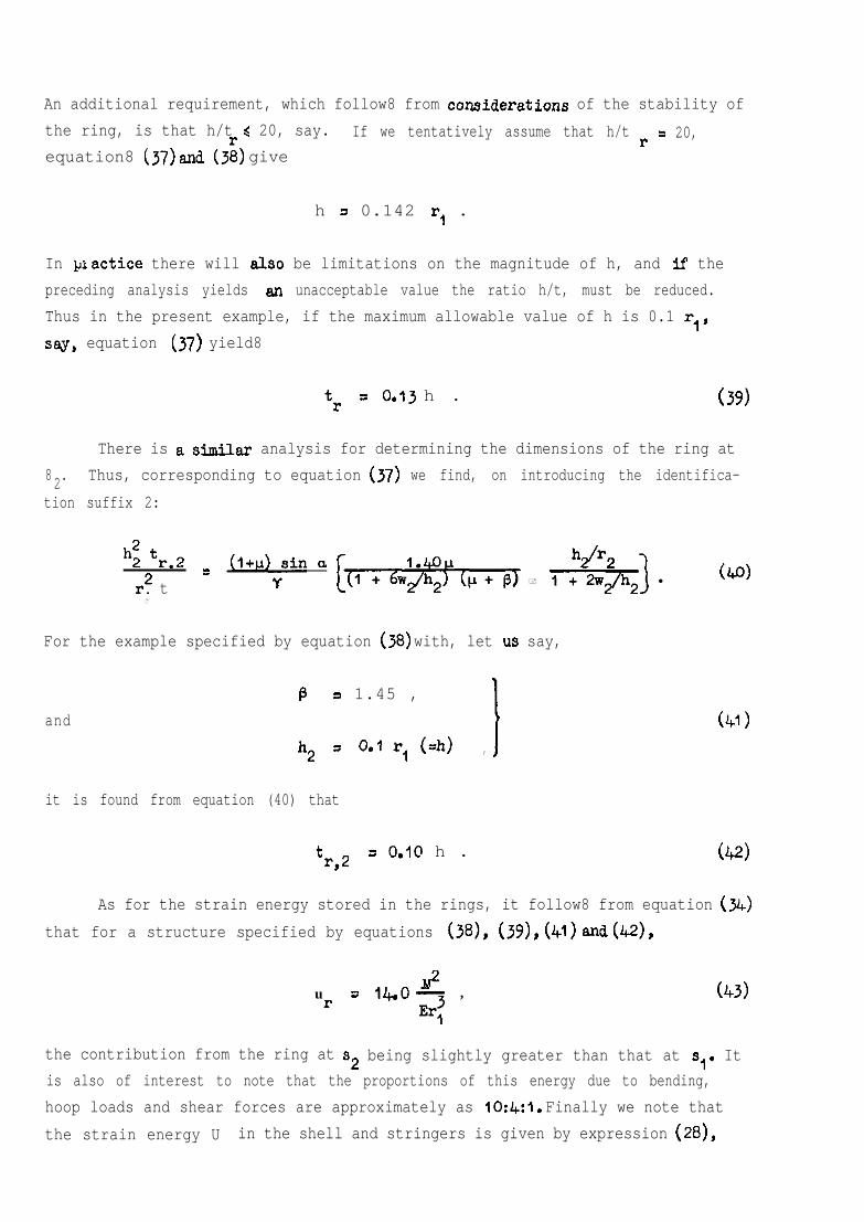
An additional requirement, which follow8 from CO?ksideratiOnB of the stability ofthe ring, is that h/t d 20, say.equation8 (37) and (3:) give
If we tentatively assume that h/t r = 20,
h = 0.142 r, .
In practice there will also be limitations on the magnitude of h, and if thepreceding analysis yields an unacceptable value the ratio h/t, must be reduced.Thus in the present example, if the maximum allowable value of h is 0.1 r,,say, equation (37) yield8
tr = 0.13 h . (39)
There is a similar analysis for determining the dimensions of the ring at8 .2 Thus, corresponding to equation (37) we find, on introducing the identifica-tion suffix 2:
hii tr.2r2 t
=☺�+qin a ☯e + *) l (40)
1
For the example specified by equation (38) with, let us say,
andB 3 1.45 ,
h2 = o.lr,(=h) ,
it is found from equation (40) that
tr,2
= 0.10 h .
(41)
ka
As for the strain energy stored in the rings, it follow8 from equation (34)that for a structure specified by equations (38), (39), (41) and (42),
u M2r = ILO- ,
Er:
the contribution from the ring at s2 being slightly greater than that at 8,. Itis also of interest to note that the proportions of this energy due to bending,hoop loads and shear forces are approximately as 10:4:1. Finally we note thatthe strain energy U in the shell and stringers is given by expression (28),
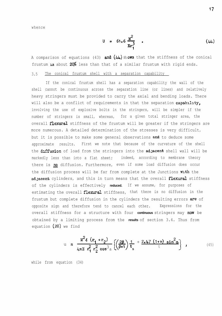
whence
A comparison of equations (43) and (44) hs OR-S that the stiffness of the conicalfrustum 1s about 2C$ less than that of a similar frustum with rigid ends.
3.5 The conical frustum shell with a separation capability
If the conical frustum shell has a separation capability the wall of theshell cannot be continuous across the separation line (or lines) and relativelyheavy stringers must be provided to carry the axial and bending loads. Therewill also be a conflict of requirements in that the separation capabdlty,involving the use of explosive bolts in the stringers, will be simpler if thenumber of stringers is small, whereas, for a given total stringer area, theoverall flexural stiffness of the frustum will be greater if the stringers aremore numerous. A detailed determination of the stresses is very difficult,but it is possible to make some general observations and. to deduce someapproximate results. First we note that because of the curvature of the shellthe diffusion of load from the stringers into the adJacent shell wall will bemarkedly less than into a flat sheet; indeed, according to membrane theorythere is 2 diffusion. Furthermore, even if some load diffusion does occurthe diffusion process will be far from complete at the Junctions with the&laced cylinders, and this in turn means that the overall flexural stiffnessof the cylinders is effectively reduced. If we assume, for purposes ofestimating the overall flexural stiffness, that there is no diffusion in thefrustum but complete diffusion in the cylinders the resulting errors are ofopposite sign and therefore tend to cancel each other. Expressions for theoverall stiffness for a structure with four continuous stringers may now beobtained by a limiting process from the results of section 3.4. Thus fromequation (20) we find
u =M2P, (r, +r2) sin2a22 34KE r, r2 cos
+ + 2.47 (l+v)t 9 (45)
a S
while from equation (34)
18
+ 0.0744 (i+v) l (46)
There is also a contribution from the reinforcing rings at separation lines:
ii sr M2 p2a p.ocoo57 1 e + 0.0430 1 & + 0.0045 1 $J . (47)
The derivation of equation (47) is given in Appendix C. It relates to thein-plane distortion of the rings and is based on the assumption that the onlytransfer of shear across a separation line OCCUTS at the stringer positions(e = 0, -+, 7c). It is also assumed that reinforcing rings adjacent to a commonseparation line have the same stiffness so that, from symmetry, a typical quad-rant of a ring - bounded by 0 = 0, $x, say - is effectively clamped at 0 i 0 andsimply supported at 0 = &x. The forces per unit length acting on such a ringare directed tangentially and are given by
Te = we, (M” = hi)
M tan ai"n '
(48)
These forces cause the following hoop loads, shear forces and bending moments:
Pn = ’ “,” a (0.208 oos e - 0.174 sin 0) ,n
v, = ' ","" a (0.250 - 0.174 oos 8 - 0.208 sin 8) ,n
mn = M tan 0, (0.219 - 0.25oe - 0.208 00s e + 0.174 sin e)
Optimum stringer area/skin thickness for maximum overall flexural stiffness
The msximisation of the overall flexural stiffness is equivalent tominimisation of the expression (U + U, + fir) defined by equations (45)-(47).
The terms ts and t occur only in the expression for U (due, in part, to theunderlying assumptions) and accordingly the optimum ratio ts/t can be determinedindependently of the dimensions of the various reinforcing rings. Now the totalweight of the skin and four stringers is proportional to
If this total is kept constant, it may readily be shown that the mxximum valueof U oocurs when
tIJ =y= +t = (&Jiz$ cosec a ’
= 3.86 if p = 1.45, a = lo’, Y = O-3 w l
This expression must be regarded as an upper limit because of the underlyingassumption of zero load diffusion from the stringers; if the skin is assumedto be 2% effective in carrying direct forces Ns, the optimum value for ts/tis about 3.1 in the above example. [Equation (51) is appropriate to thefrustum with four stringers. If the number of stringers is increased theassumption of zero load diffusion becomes increasingly untenable. The limit-ing case is when there is complete diffusion and the stringers can be regardedas a stringer-sheet. The optimum value of p for this case can be obtainedby minimisation of expression (Y), 3ubJeCt to the constancy of eXpreSSiOn (50).This results in the following equation for p:
2(l+v) p2 sin2a + 2b2(&L+ D+ll
d P2-1 1l,(v) = B+lml , (52)
which yields a non-zero value of in only when
6(1+v) sin*a < (@-1)2/p .
'The fact that non-zero solutions are possible in certain circumstances issimply because the axial variation of the section srea of the stringers(a constant) is nearer to the optimum variation, namely l/s, than is that ofthe skin, which varies in direct proportion to 3.1
20
Optimum thickness of reinforcing rings for maximum overall flexural stiffness
Let us now assume that the parameter p is given - possibly byequation (51) - and that the reinforcing rings at the ends of the frustum aresimdar to that in Fig.7 with w = $h, so that - dropping the suffices I,2 -
(53)
If we further assume that h,, h2 are given, the corresponding optimum value oftrl andtr 2 may be determined in terms of t and the overall geometry of the
frustum for'maximum overall flexural stiffness. The total weight of the skinand stringers plus one (arbitrary) ring is proportional to
ntr, t~~ (I+ B+ 21.4 + 4mhtr .
If this total is kept constant while t and tr are varied it may be shown thatthe overall flexural stiffness is a maximum when (with Y = 0.3)
t2
r,r2 sin a l.l(l+ p+ 211) 3
t =>
(0.011 + 0.276 h*/r*)- .:h2 P + 1.60~ (e+l) sin*a
. . . (54)
If the reinforcing rings at separation lines are of the form specified byequation (53) it may likewise be shown that the overall flexural stiffness is amaximum when
5 rlr2 sin a
Id'+ @+*ldt =h2 p + 1.60~ (p+l) sin*
(0.00027 + 0 . 043 h2/r2)' .
. . . (55)
21
.
4 EXPERIMENTS ON XYLONl!l!E CONICAL E'RUSTUM SHELLS
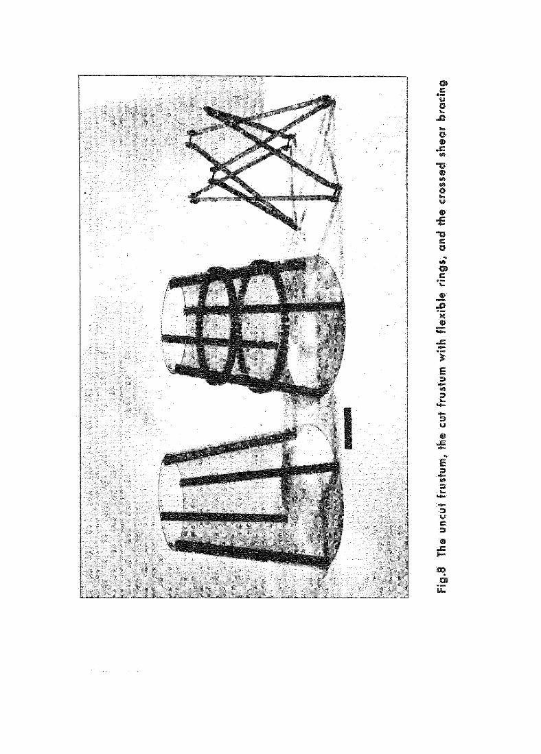
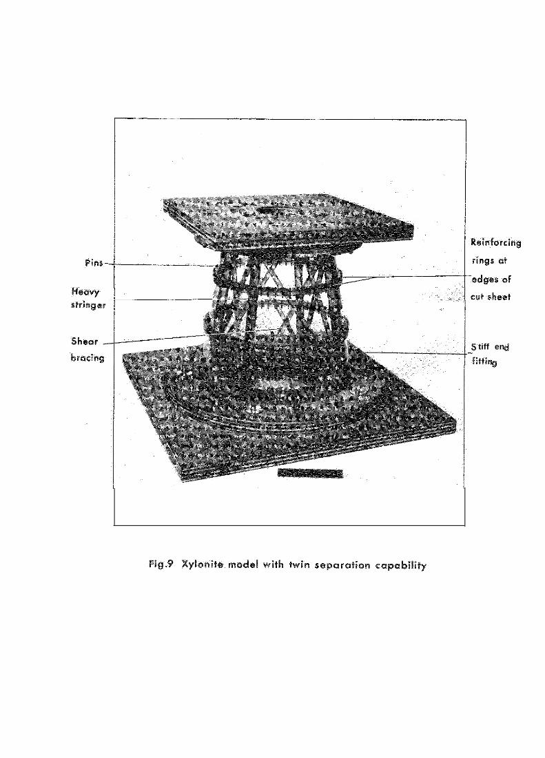
Tests on a series of models have been performed to gauge the effuxcy ofdlfferent methods for provuiing a (twin) separation capability without an unduedrop in the overall flexural rigidity. For ease of manufacture the models,which have four equally spaced stringers, were constructed of xylonite(cellulose nitrate). There were basically two conical frustum shells with thesame overall diman3ions. In one of these the shell wall was continuous; theoverall flexural stiffness of this model provided a yardstick against which theother(s) could be compared. The wdl of the other shell was out along twocu-cumferences; the overall flexural stiffness was then measured for this shelland for ten modified versions, the modifications including a variety of addi-tional stiffening (end combinations thereof) including external reinforcingrings at the out edges, push-fit pins (axially orientated) connecting adJacentreinforcing rings, and an internal crossed shear bracing. The shells and themodifications are shown in Figs.8 and 9, while Fig.40 shows a model in the testrig. To simplify the interpretation of the results the ends of the shells wereclamped to stiff attachments, as shown in Fig-Y. The effect of flexible endattachments can, of course, be estimated from the preceding analysis.
4.1 Model dimensions
The dimensions of the uncut shell are
4, = 10.5 in ,
c&=10" ,
2rl=8in ,
2r2 = 11.7 In ,
(p = 'Jr, = l-46) s
t = 0.040 in ,
*s= 0.3 in2 , (depth 0.6 in, wzdth 0.5 in) ,
(2A
v = s = 1.19Tt >
,
E = 280,000 lbf/in2 .
2 2
The structure extended an additionsl inch at each end to facilitate clamping to
the stiff ply end fittings.
The shell with the twin separation capability is as specified above, butwith circumferential cuts (0.075 in. wide) in the shell wall at .sxial distancesfrom the smaller end of 2.7 in. and 6.6 in. The members of the internal crossedshear bracing are of square cross-section (0.3 in. x 0.3 in.) and each end isattached to a stringer by a 4 B.A. bolt, as shown in Fig.9. The four externalreinforcing rings at the cut edges of the shell well are of two kinds, stiff andflexible. Each 'stiff' ring measures $ in. in the sxisl direction while thedepth at the cut edge is 0.27 in.; the inner face of each ring is tapered tofollow the skin surface to which it is glued: the outer face is cylindrical, sothat the depth of the rings varies slightly in the axial direction. Holes ofj/j2 in. diameter were drilled axially through adjacent rings at an angularspacing of 6’; a shear connection can thus be obtained by the insertion of'push-fit' steel pins which bridge the gap across the cuts without detractingfrom the separation capability.
Each 'flexible' ring was obtained by cutting away sections of the 'stiff'ring between adjacent drill holes; this produced a castellated ring withadequate shear connection (with pins in) but negligible hoop and flexuralrigdity. The rings were cut away to within 0.020 in. of the shell wall, andthe width of each cut was such that the remaining sections were 0.0344 in.wide, i.e. (l/8 + j/32 + l/8) i n . The flexible rings are shown on the frustumin Fig.8.
4 . 2 The tests
The tests were to determine the overall flexural stiffness of the models.A typical model, supported as a vertical csdXi.ever, is shown in the test framein Fig.10. The moment was applied to a horizontal steel channel beam bolted tothe stiff upper end fitting. Did. gauge readings gave the rotation of this beamand hence the overall stiffness of the model. [A slight adJustment was made, bycalibration, to account for bending of the beam itself.1 Separate tests weremade with the stringers at 0 = 0, etc. end at 8 = ix, etc. slthough, in theory,the corresponding overall flexural stiffnesses should be the same. In practicethe stiffness appropriate to the &zero position exceeded the other in allcsses by about I@. This feature can be attributed to differences in theefficiency of the end clamping of the skin and stringers. Here, only the sver-age value of the two stiffnesses is quoted. Furthermore, for ease of inter-pretation, the overall flexursl stiffnesses are expressed as fractions of thestiffness of the uncut shell. In this connection it is worth noting that the
23
.
experimentally determined stiffness of the uncut shell agreed exactly with thatderived from equations (4) and (28).
4.3 Test results
The overall flexural stiffness of the uncut frustum is, by definition,unity. In terms of this the stiffness of the cut frustum is 0.30. Table 1shows the stiffness of the cut frustum with various reinforcements. The pinspacings quoted refer to the angular spacing between stringers so that, forexample, a 45' spacing implies 4 pins per pair of adjacent rings; similarly30’ implies 8 pins.
Table 1
Relative stiffness of cut frustum with reinforcements
flexible rings, no pins 0 . 3 2
flexible rings, pins at 45’ 0 . 4 9flexible rings, pins at 30’ 0 . 5 2flexible rings, pins at 22$ a 57flexible rings, pins at 6’ 0.74*
stiff rings, no pins 0 . 5 4stiff rings, pins at 6’ 0.74+
crossed bracing, no rings 0 . 5 2crossed bracing, stiff rings, no pins 0 . 6 3crossed bracing, stiff rings, pins at 6” 0 . 8 0
"Best buy.' +Note the equality with line . With continuous sheartransfer there is no tendency for the rings to bend.
The test results demonstrate the importance of a multiple shear connec-tion across a separation line. In an actus.l. missile structure the rings would,of course, be on the inside and there would also be differences in the detailsof the shear connections.
5 CONCLUSIONS
Some aspects of the design of a conical frustum shell with a separationcapability have been considered theoretically and experimentally. Particularattention has been paid to the determinatxon of the overall flexural stiffnessof the frustum, and to ways of maxiaising this stiffness. Such ways includethe following:
(4 increasing the number of (continuous) stringers,
(b) optimum choice of stringer section area/skin section area,
(c) provision of multiple shear connections across a separation line,
(a) optimum design of reinforcing rings at the ends of the frustum(markedly dependent on (a)),
(e) ditto for rings at separation lines (markedly dependent on (c)),
(f) optimum tapering of skin and stringers (not discussed in detail).
.
Appendix A
STRESSES IN AN ANNULS3 PLATE AT THE ENDS OF THE FRUSTU?d
In this Appendix a stress-function solution is presented for the stressesin an annular plate of thickness tr, bounded by inner and outer radii ro, I,respectively; the loading on the outer boundary is given by equation (11) ofthe main text, while the inner boundary is free. The loads on the outer bound-ary Cause radial and shear stresses
k-L = K COB 0 ,1 1
whereK _ Mtana
7ct r2.
r 1
(56)
These stresses form a self-equilibrating system and, with the inner boundarybeing free of stress, equilibrium and compatibility throughout the annulus aresatisfied by choosing a single-valued stress function which satisfies thebiharmonic equation and the boundary conditions. A suitable function whichsatisfies the biharmonic equation is given by
9 z 1,b3 + br-') cos 0 , (57)
which yields stresses
u =r (a= - br-3) oos 0 ,
Oe = (3sr+br-3) cos 8 ,
Tre = (cu' - brm3) sin 0 .,.,
The vanishing‘of.the radial and shear stresses on the inner boundary issatisfied if -_
while the boundary conditions of equation (56) give
(58)
ai=1 - 0 1r4/r3] = K .
26 Appendix A
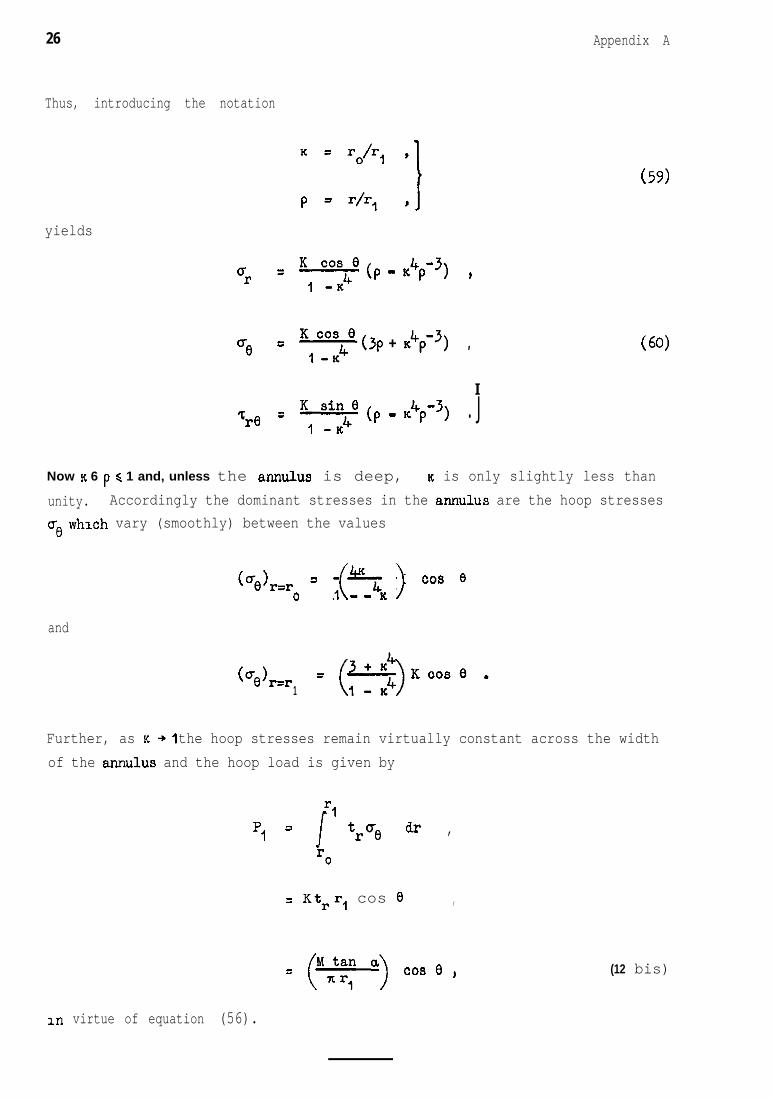
Thus, introducing the notation
yields
u =r K, y4” (P - K4F3, ,
ue 5 :“_“z4” (3p + !+p-‘) ,
I
(59)
(60)
Tre = K, s-i:40 tp - ,4p-3, . J
Now K 6 p d 1 and, unless the annulus is deep, K is only slightly less thanunity. Accordingly the dominant stresses in the annulus are the hoop stressesme whxh vary (smoothly) between the values
(~~1~~~ = 3 K ~0s e0 ( >-K
and
(ue)r‘=r1
Further, as K +I the hoop stresses remain virtually constant across the widthof the annulus and the hoop load is given by
rlP, = J true dr ,
r0
= Ktrr, cos 0 ,
= (“:z: “) cos e ,
In virtue of equation (56).
(12 bis)
27
.
.
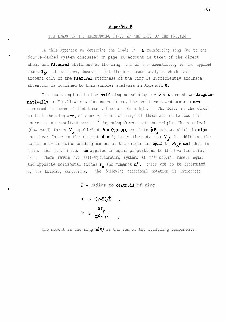
THE LOADS IN THE REINFORCING RINGS AT THE ENDS OF THE FRUSTUM
In this Appendix we determine the loads in a reinforcing ring due to thedouble-dashed system discussed on page 13. Account is taken of the direct,shear and flexural stiffness of the ring, and of the eccentricity of the appliedloads TO. It is shown, however, that the more usual analysis which takesaccount only of the flexursl stiffness of the ring is sufficiently accurate;attention is confined to this simpler analysis in Appendix C.
The loads applied to the half ring bounded by 0 6 0 6 n are shown diagrsm-maticslly in Fig.11 where, for convenience, the end forces and moments areexpressed in terms of fictitious values at the origin. The loads in the otherhalf of the ring are, of course, a mirror image of these and it follows thatthere are no resultant vertical 'opening forces' at the origin. The vertical(downward) forces V, applied at 0 = 0,~ ere equal to $Ps sin a, which is alsothe shear force in the ring at 0 = 0; hence the notation Vo. In addition, thetotal anti-clockwise bending moment at the origin is equal to nVor and this isshown, for convenience, as applied in equal proportions to the two fictitiousarms. There remain two self-equilibrating systems at the origin, namely equaland opposite horizontal forces PO and moments m'; these are to be determinedby the boundary conditions. The following additional notation is introduced,
F = radius to centroid of ring,
k = *Ir;'GA' .
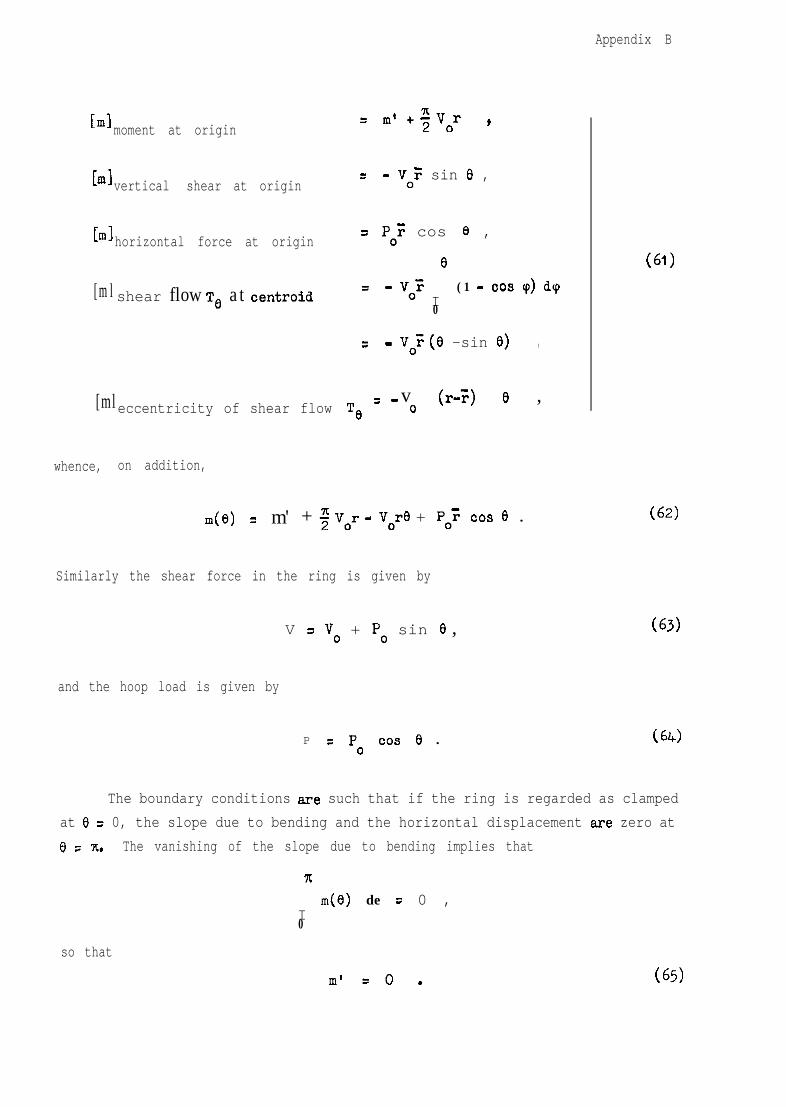
The moment in the ring m(e) is the sum of the following components:
.
Appendix B
blmoment at origin
bl vertical shear at origin
bl horizontal force at origin
[ml shear flow Te at centroid
= m’ +fvor ,
= - V,F sin 0 ,
= PO? cos e ,
e= - v,"
I(1 - 00s q) dq
0
= - voF (0 -sin e) ,
[ml v (r-3 e ,eccentricity of shear flow Te = - o
whence, on addition,
m(e) = m' + $ vor - vore + P,: cos e .
Similarly the shear force in the ring is given by
V = V. + PO sin e ,
and the hoop load is given by
P = P, cos e .
(61)
(62)
(63)
(64)
The boundary conditions are such that if the ring is regarded as clampedat Cl = 0, the slope due to bending and the horizontal displacement are zero at8 = T. The vanishing of the slope due to bending implies that
?r
Im(e) de = 0 ,
0
so that
m’ =o. (65)
Appendix B 29
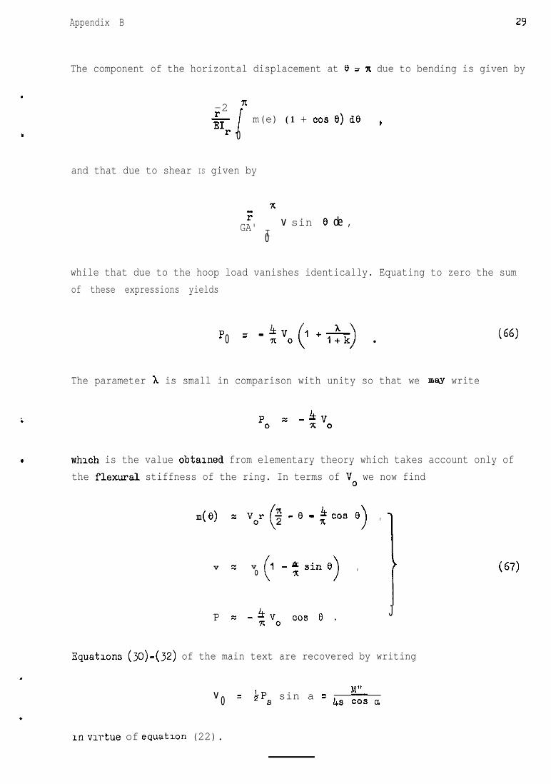
The component of the horizontal displacement at 0 = n due to bending is given by
.
-2 =LE1r J
m(e) (1 + co9 e) de )0
and that due to shear IS given by
7[;:
GA' Iv sin 8 de ,
0
while that due to the hoop load vanishes identically. Equating to zero the sumof these expressions yields
p =-0 *vo(,+*) l
The parameter h is small in comparison with unity so that we may write
(66)
which is the value obtalned from elementary theory which takes account only ofthe flexural stiffness of the ring. In terms of V. we now find
d 0) = vor($ - e - ~ cos eIt
),
v z v 1-xsin80(
4
>,
1
v. ~0.3 e . J
Equations (30)-(32) of the main text are recovered by writing
v =0 $7Ps sin a = 4s fi, a
In virtue of equation (22).
(67)
30
Appendix C
THE LOADS IN THE REINFORCING RINGS AT SEPAFUTION LINES
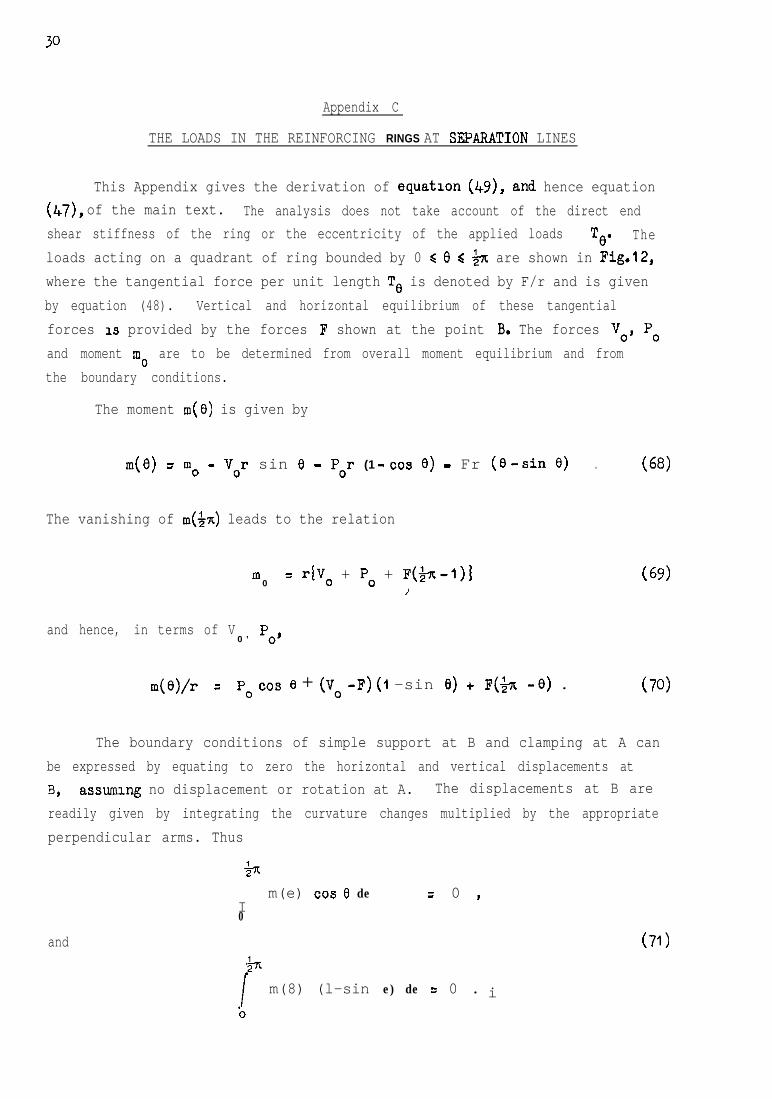
This Appendix gives the derivation of equation (by), and hence equation(47), of the main text. The analysis does not take account of the direct endshear stiffness of the ring or the eccentricity of the applied loads TO. Theloads acting on a quadrant of ring bounded by 0 < 0 d $x are shown in Fig.12,where the tangential force per unit length TO is denoted by F/r and is givenby equation (48). Vertical and horizontal equilibrium of these tangentialforces 1s provided by the forces F shown at the point B. The forces Vo, POand moment mo are to be determined from overall moment equilibrium and fromthe boundary conditions.
The moment m(0) is given by
m(e) = m. - Vor sin 8 - P,r (1 -cos 0) - Fr (O-sin 0) . (68)
The vanishing of to(&) leads to the relation
m0
= riVo + PO + F($x-I)]/
(69)
and hence, in terms of V0 ’ pO’
m(e)/r = p. cos e + (v. -F) (1 -sin e) + F($3 -e) . (70)
The boundary conditions of simple support at B and clamping at A canbe expressed by equating to zero the horizontal and vertical displacements atB, assuming no displacement or rotation at A. The displacements at B arereadily given by integrating the curvature changes multiplied by the appropriateperpendicular arms. Thus
b
Im(e) cos e de = 0 )
0
and
m(8) (l-sin e) de = 0 . i
(71)
Appendu C 31
Substitution of equation (70) mto equations (71) and solving for Vo, PO gives
and
vv 3300FF
= a-21+7t+10x2-7c= a-21+7t+10x2-7c
6x2-t6Tc--8 *6x2-16~--8 '
PP""FF
= bo-= bo- 16x + x216x + x23x2 - an - 43x2 - an - 4 ** IJ
(72)
Expressions (70) and (72) suffice to determine the bendmg moment m(e), whilethe shear force and hoop load may be determined from the relations:
V = V. cos 0 + PO sin 0 + F(1 -cos 0) ,
P = PO 009 e + (F-vo) sin e .(73)
32
REFERENCES
NO. Author Title. etc.-
1 W. Fliigge "Stresses in Shells", Springer-Verlag, 1960
The following papers are on topics closely related to the present investigation:
2 A. Waltien Asymmetrical loading of conical shells.Trans. Roy. Inst. Technol., Stockholm No.218, 1963
3 H. Becker Design of cylinder-cone intersections.J. Spacecraft and Rockets 1, 1, 120-122, Jan/Feb 1964
4 B. Wilson Asymmetrical bending of conical shells.Proc. Amer. Sot. Civ. Engrs. 86, EN3, 119-139, June 1960
_----
\\22
ll ..
//f I’
/ -/
3 3.51I.0 I.5 2.0 2.5 p 3.f
Fig. 2 Flexural stiffness of unreinforced frustum shell, rigid ends.
8 ’
J --
I I I2.0 2.5
P3-o
Fig. 3 The function F3(A&)
P0.25
- 0.5
- o-75
j 4.0
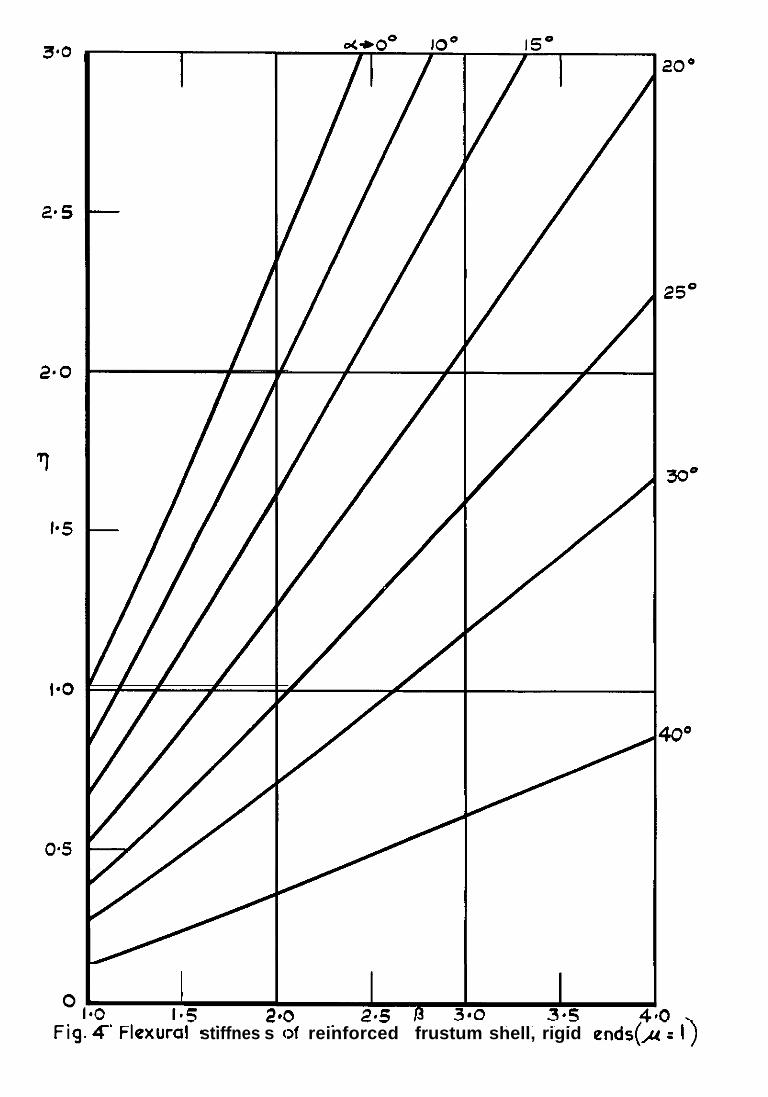
I>-.stiffnes s c >f reinforced frustum shell, rigid ends(,u =
. 0
IO0 15
7
+
20°
E0
30*
4o”
3
Fig.5 Flexural stiffness of reinforced frustum shell, flexible ends @=I, r=l)
T0
-
-
?t
.
ni
0-L
l&rl&r 33
I lI l
-7-744 --------
Fig.7 Cross-section of reinforcing ring
.-0
ins-
tiff en
-fitti”
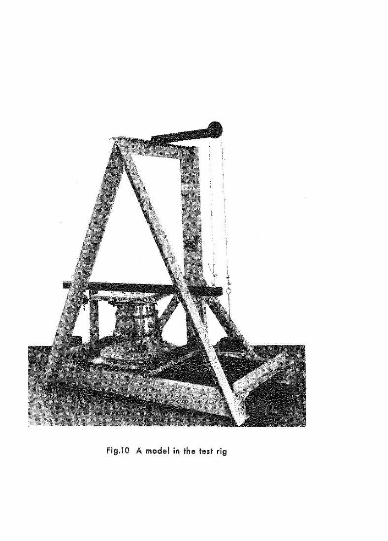
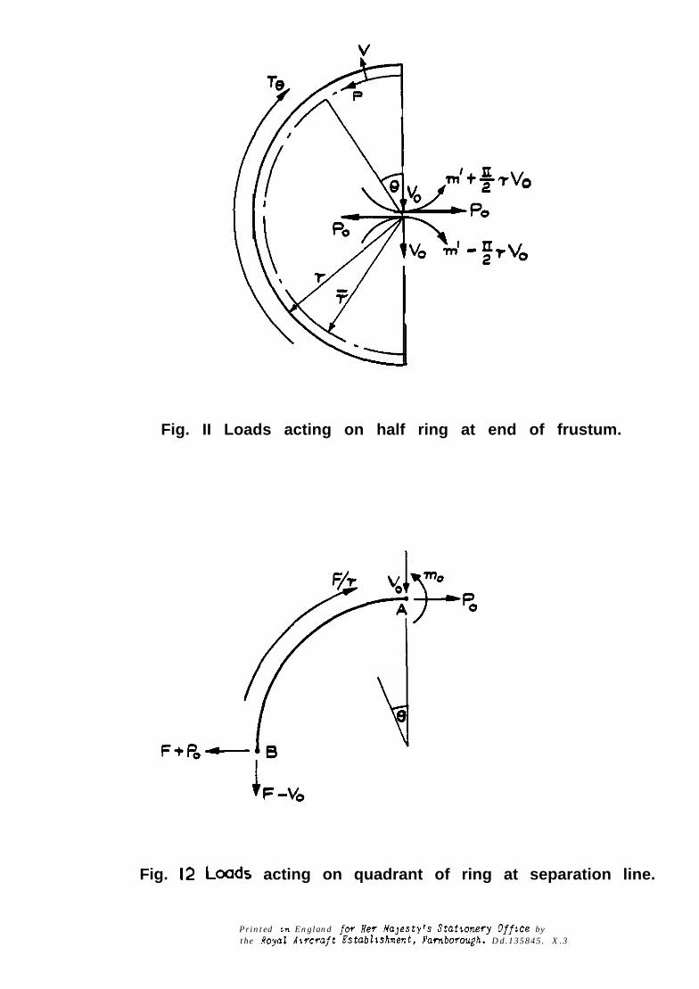
Fig. II Loads acting on half ring at end of frustum.
Fig. 12 Loads acting on quadrant of ring at separation line.
Printed tn England for Her Majesty’s Statronesy Offsce bythe Royal Alrcsaft Establrshnent, Fambosmqh. Dd .135845 . X .3

A&C. C.P. No.1039October 1967
mnsIield, E.H.
539.384 :621434.1 :@l -43’4.5 :~621~448.1 :G&078.8 :
O N TIE FLEXURE O F A C O N I C A L FRll- WELL 621.8C7 :“29.15.01’.25
A.R.C. C.P. No.1039October ,967
M’ansIleld. E.H.
O N THE FI.EXURE O F A C O N I C A L FRUSRM SHELL
53Y.3@4 :621-434.1 :621~43$. 5 :5?1-48.1 :621,.075.6 :..? .587 :u2,.,5.012.25
A.R.C. C.P. No.1039October 1967
He.“Sfleld. E.H.
ON ‘INHE FLEXUPS OF A CONICY “UGRm S”LlL
539.384 :621~w4.1 :621 -!A.5 :521-u&, :62LO78.8 :621.887 :629.19.012.25


C.P. No. 1039
0 Crown copyright 1969
Published by
To be purchased fro,,,49 High Holbom, London w c 1
13~ Castle Street, Edinburgh 2109 St Mary Street, CarduT crl IJW
Brazennose Street, Manchester 250 Falrfax Street, Bristol BSl 3DE
258 Broad Street, B,muogham 11 Llncnhall Street, Belfast BTZ SAY
or tbmu&h any bookseller
C.P. No. 1039
SBN 11 470166 0