Embed Size (px)
Citation preview
M I N I S T R Y OF AVIATION
R. & M. No. 3265
AERONAUTICAL RESEARCH COUNCIL
REPORTS AND MEMORANDA
On the Flow in a Reflected-Shock Tunnel By D. W HOLDER, P h . D . , DiSc . and D. L. SCHULTZ, B.E. , D . P h i l .
OF THE AERODYNAMICS DIVISION, N.P.L.
LONDON: HER MAJESTY'S STATIONERY OFFICE
I962 FOURTEEN SHILLINGS NET
On the Flow in a Reflected-Shock Tunne l By D. W. HOLDER, P h . D . , D . S c . and D. L. SCHULTZ, B.E. , D . P h i l .
OF THE AERODYNAMICS DIVISION, N.P.L.
Reports and Memoranda No. 3 2 @ *
August ±960
Summary. The performance of a shock tunnel operated by the reflected-shock technique is examined
theoretically neglecting viscous effects and high-temperature real-gas effects. Particular attention is gi+en to
disturbances to the flow at the nozzle entry caused by waves reflected from the contact surface when the
operating conditions depart from those for 'tailoring'. For unheated hydrogen driving air, the results suggest
that the first disturbance reflected from the contact surface is weak enough to be tolerated only within a
small range of primary-shock Mach number, Ms1 (e.g., 5"7 < Ms1 < 6"3 if the pressure at entry to the nozzle is to remain constant to _+ 10 per cent). Within this range, running times much longer than those
obtained in 'straight-through' shock tunnels are predicted, the limitation usually being imposed by the
arrival of the expansion wave originating at the diaphragm.
Outside this range of Mach number, the uniform-flow duration between the arrival at the nozzle entry of
the primary shock and the first disturbance reflected from the contact surface is shown to be approximately
equal to the time between the arrival of the primary shock and the contact surface in a 'straight-through' shock tunnel. At first sight it appears, therefore, that the advantages of reflected-shock operation are confined
to a very narrow range of shock Mach number, unless a l~eated driver gas is used in order to vary the Mach number for 'tailoring'.
Further analysis suggests, however, that subsequent disturbances in the multiple wave reflection process between the contact surface and the end of the tube are relatively weak over a useful range of shock Mach
number. Thus, if the flow after the arrival of the early reflected disturbances is used for test purposes, long running times seem possible in theory without severe restrictions to the shock Mach number.
Experiments have been made in a shock tube and a shock tunnel to provide data for comparisons with the
results of the simple theory. If allowance is made for viscous effects on the motion of the contact surface,
fair agreement is found for the disturbances reflected and transmitted by the contract surface, and for the
arrival of the expansion wave. It is, however, observed that the pressure gradient in the multiple reflection
process increases when the shock Mach number is raised substantially above the 'tailored' value, and a limit
to the usable flow duration may result.
A striking feature of the results is a,fall of pressure at the end of the tube immediately after reflection of the
primary shock. This is attributed to attenuation of the reflected shock resulting from its interaction with the
boundary layer on the wall of the tube. Further research is required to check this explanation, and to
investigate the effects of Reynolds number and of the cross-sectional shape and size of the tube. The effects
of the tail and reflected head of the expansion wave originating at the main diaphragm are discussed. It is
shown that the arrival of the reflected head at the nozzle entry may impose a severe limitation to the duration of uniform conditions at low'shock Mach number, and that the arrival of the tail may limit the flow duration
at high shock Mach number. Unless means can be devised to suppress the expansion wave, it is demonstrated
that it is desirable to have alternative diaphragm positions in a tube required to operate over a range of shock Mach number.
e Previously issued as A.R.C. 22,152. Published with the permission of the Director, National Physical Laboratory.
It is concluded that running times of order 10 milliseconds at a shock Mach number of 4, falling to, perhaps, 1 millisecond at a shock Mach number of 8 seem possible in a shock tunnel of reasonable size by using reflected-shock operation with unheated hydrogen driving.air. Because of the simplifying assumptions of the theoretical investigations, and the deficiencies of the apparatus used for the experiments, the present investigation must, however, be regarded as preliminary in character. Further research is required to check and extend the findings, and topics particularly requiring investigation are listed in the Paper.
1. I , ztroduction. It is well known that the duration of steady flow at the working section of a
shock tunnel is extremely short when the tunnel is operated at high shock Mach number in order
to provide test conditions of high stagnation enthalpy. This leads to difficult instrumentational
problems associated with the measurement of the properties of the test stream and the loading on
the model under test, and even to questions as to whether the flow pattern near the model achieves
a steady state before the uniform free-stream flow ends. It is, therefore, important to examine
techniques for increasing the flow duration, and the use of the reflected-shock technique is one
method that has been suggested I for achieving this result.
The duration of steady flow at the working section is determined by the steady-flow duration at
entry to the expansion nozzle, and by the starting process of the nozzle. The latter has been discussed
in, for example, Ref. 2, and the present Report is concerned with the flow in the driving tube upstream
of the nozzle entry. If the apparatus is arranged so that the flow from the driving tube passes directly
into the nozzle, the duration of uniform entry flow is equal to the time between the arrival of tile
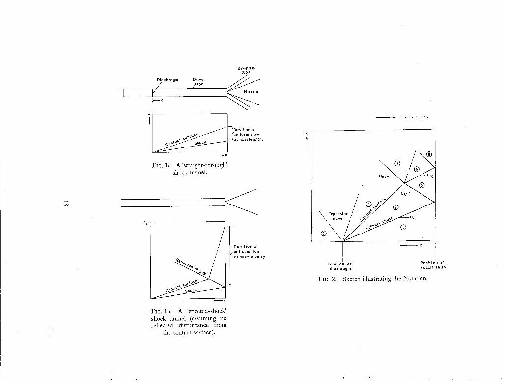
shock and the contact surface at the nozzle entry as sketched in Fig. la. To achieve this method
of operation, it is necessary to use a driving tube of diameter equal to that of the nozzle entry, or,
more usually, to use a larger tube and to by-pass the flow not required by the nozzle. With the latter
arrangement, a large proportion ~ of the uniform hot gas between the shock and the contact surface is,
in effect, wasted. If, however, the end of the driving tube is closed, apart f rom the nozzle entry,
the primary shock will be reflected as sketched in Fig. lb, and the velocity of the gas behind it,
and of the contact surface, may be greatly reduced. I f it can be arranged that no disturbance is
reflected from the contact surface back towards the nozzle entry, the whole of the hot gas ahead of
the contact surface is then, in principle, available for supplying the nozzle, and the duration of
uniform flow can be increased. In this case the contact surface moves slowly towards the nozzle
entry at a speed determined largely by the rate of mass flow into the nozzle; uniform conditions
may then be terminated by the arrival of the expansion wave originating at the diaphragm.
The elementary theory~ of the reflected-shock tunnel is outlined below, with particular reference
to the interaction of the reflected shock with the contact surface. Th e results of experiments are included for comparison.
To reduce viscous effects on the motion of the primary shock it is necessary to keep the ratio of the length to the diameter of the driving tube below a value of order 100. The length of the tube must be large in order to provide adequate time between the arrival of the shock and the contact surface, and the result is that the diameter of the driving tube cannot be very small; typical values lie between 3 in. and 6 in. For hypersonic operation with a reasonable working-section size, this diameter is much larger than that of the nozzle entry (about 1 in. for a 30 in. diameter working section at M = 15), so that it is necessary to by-pass most of the shock-heated gas.
The derivation of the basic equations is not reproduced in detail, since it is given in several places (e.g., Ref. 3) in the literature.
2. The Performance of'a Reflected-Shock Tunnel According to Perfect-Gas Theory. Assuming perfect-gas behaviour, and that the ratio of specific heats, 7, is the same for the driver and driven gases, the equations given below determine the motion of the shocks and contact surface, and the associated gas motion in the tube. The notation of Fig. 2 is used to indicate the separate regions in which conditions are uniform, and the ratio y,Jy~ of the value of a quantity y in region m to that in region n is denoted by y,~,~. Numerical values of the quantities of interest in the operation of reflected-shock tunnels have been computed, assuming that the driv:er and driven gases are hydrogen and air respectively at initially equal temperatures. The corresponding values of 7 and the initial ratio of sound speeds, a14 , have been taken as 1.40 and 0.263 respectively. It is assumed that the proportions of the apparatus are such that the expansion wave originating at the diaphragm position does not affect the flow at the nozzle entry within the time interval considered.
2.1. The Primary Shock. The pressure ratio P~I across the primary shock is related to the initial pressure ratio P41 across the diaphrag m by the equation
where
and
7 + 2 ( X - -
7 - 1 '
( 1 )
7 - 1
The Mach number )1~1 (= USa1) of the primary shock is related to P21 by the equation
2 = 5( P 1 + 1). (2)
The velocity u 2 of the flow behind the primary shock, in terms of the initial speed of sound a 1 in the driven gas, is given by
u 2 3(p~i- 1) a~ = (~P21 + 1) l&" (3)
where
= 2)"
The velocity u 2 is equal to the velocity of the contact surface, and to the velocity u 3 of the flow behind the contact surface. The speed of sound a~ in the gas behind the shock is given by
a2~ k@~+l J " (4)
2.2. The Contact Surface. The static pressure Pa behind the contact surface is equal to the pressurep~ ahead of it, and is given by Equation (1). Similarly, the velocity u 3 is given by Equation (3) or, alternatively, it may be derived from equations for the expansion wave in which the driver gas expands when the diaphragm bursts; these give
zt 3 1
a4 7# - - - - E1 - (pi p,,Y] • ( 5 )
(sash6) A 2
The speed of sound, %, behind the contact surface is given by
%4 = (P14P2x) ~, (6)
so that the Mach number us/a3, is given by
zig _ 1
a3 yfi [(p,4pzl)-~ - 1]. (7)
The speed of sound ratio aa~ across the contact surface follows from Equations (4) and (6) as
a~ = %(p~4p21)~ LP~-~)J " (8)
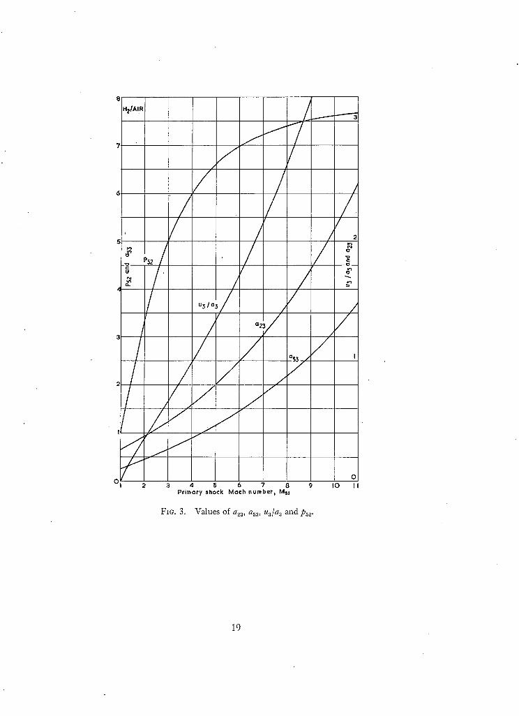
Values of u3/% and a23 calculated from Equations (7) and (8) are plotted in Fig. 3, where they are
shown in terms of Msl by the use of Equations (1) and (2).
2.3. The Primary Reflected Shock. If the nozzle entry is assumed to be small compared with the
diameter of the driving tube, the end of the tube may be regarded as effectively dosed. The velocity u 5 behind the reflected shock is then zero, and, under these conditions, the pressure ratio Ps~ across
the reflected shock is given by
p = ( ~ + 2) - 1 P~ = Psa = - , (9)
P21 + o~
and the velocity U~ 2 of the reflected shock is given, in terms of that U.s l of the primary shock, by
Us~ (~ -1 ) + 2p21 - ( 1 0 )
Usl 1 + ~P2i
The speed of sound behind the reflected shock is given by
as~ L ~P~2 + 1 J (11)
Values of P53 calculated from Equations (2) and (9) are plotted in Fig. 3, and values of Us~/a ~
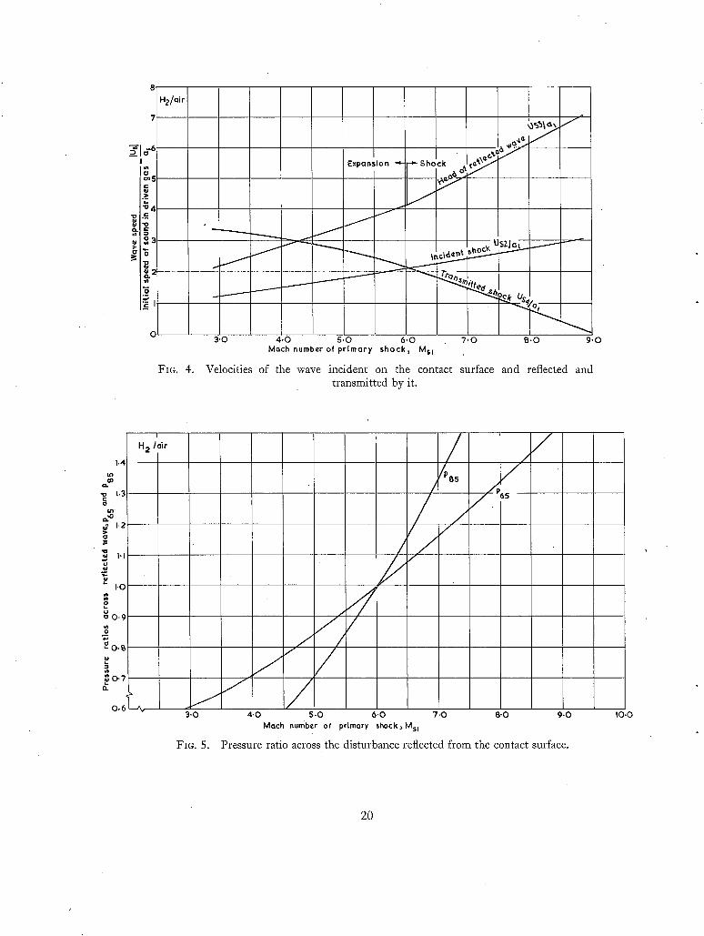
calculated from Equations (2) and (10) are shown in Fig. 4.
2.4. The Interaction of the Reflected Shock with the Contact Surface. When the shock (referred to in this section as the incident shock), resulting from reflection of the primary shock from the closed end of the tube, meets the contact surface there will, in general, be a reflected disturbance, which may be an expansion or a shock wave, and a transmitted shock wave. After interaction with the
contact surface, the requirements that must continue to be satisfied are equality of static pressure
and velocity on the two sides of the contact surface. Thus, with the notation of Fig. 2, we have
P6 = P7, and u 6 = z/7.
If the absolute gas velocities upstream and downstream of a shock are denoted by u~, and u a
respectively, and are taken as positive in the direction of motion of the shock, the velocity change
across the shock is given by
ua, - u~, = S(Pa,- i)(aPa,+ 1) -~/" (12) a~t
4
where a~ is the speed of sound in the gas ahead of the shock, and Pa,~ is the pressure ratio across the shock. Thus, taking velocities positive in the sense indicated in Fig. 2, we have for the shock
transmitted through the contact surface
u~ - u7 _ a ( p T ~ - 1) (~PT~ + 1 ) -v2 . a3
Since u 5 is zero, we have, if the incident shock is reflected from the contact surface as a shock
(13)
% - 8(p65- 1)(c~p05+ 1)-'/"-, (14) a 5
and, if it is reflected as an expansion wave
u G _ 1, (1-p05P). (15) a5 7/3
Since u s is equal to the velocity of the contact surface after the interaction, Equations (14) and (15)
show that the contact surface moves towards the nozzle entry if the reflected disturbance is a
shock, and away from the nozzle entry if the reflected disturbance is an expansion wave. Also,
since % = u:, Equations (13), (14) and (15) give
3(pTa - 1) (~PTa ÷ 1) -2f-° = Ua _ %aS(p~ 5 _ 1) (aPG5 + 1)->-. (16) aa
for a reflected shock, and
3(pTa- 1) (ap~ s + 1)-'/"- = --Us + ass 1 (1 -p ,aa) (17) aa
for a reflected expansion.
The velocity U~a of the reflected shock is given in terms of its pressure ratio by Equation (2) as
- [3 (~p6 ~ + 1)] q2 (18) a 5
and the head of the reflected expansion travels at the speed of sound %. The velocity Us4 of the transmitted shock also follows from Equation (2) as
Us4 - [/3(apt a + 1)]'12 _ us. (19) as aa
Equality of static pressures across the contact surface requires that for reflection as a shock or as
an expansion PTa = P , a P s a . (20)
Using values of %a calculated from Equations (2), (8), (9) and (11) and plotted in Fig. 3, and the
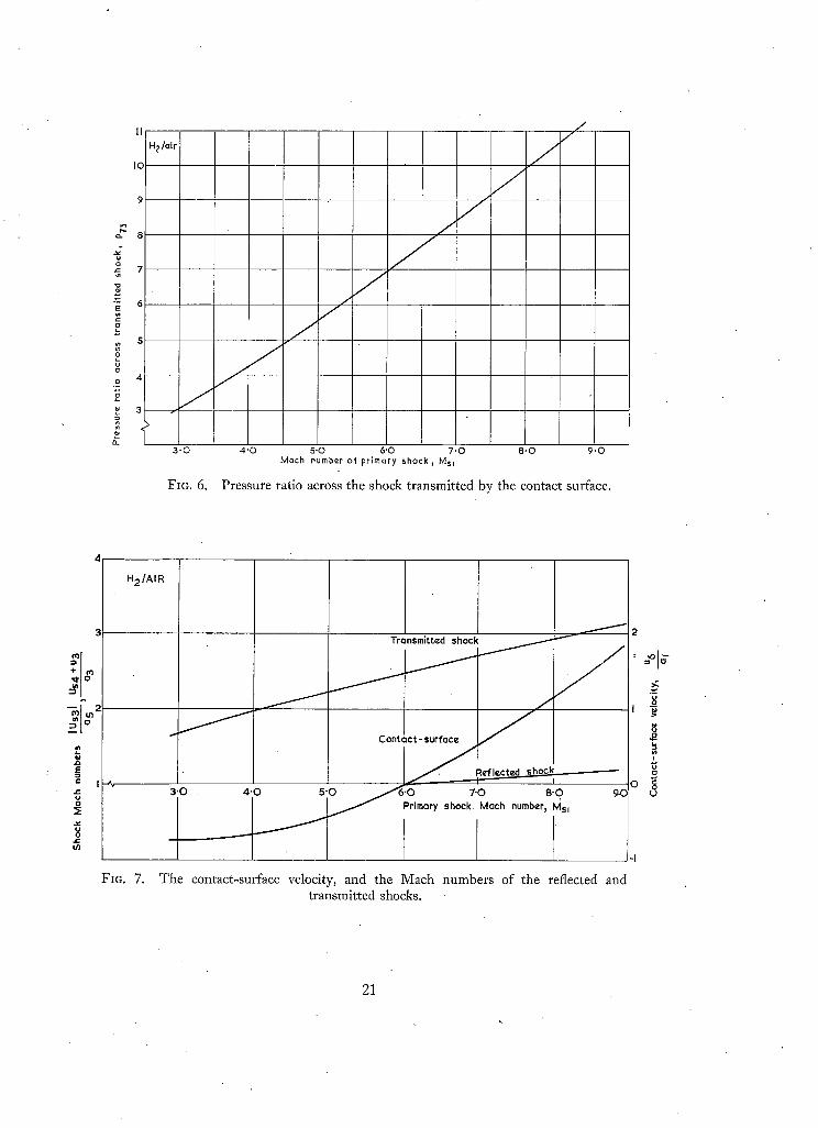
values of u a / a 3 and Psa plotted in this diagram, values of P65 and PTa have been computed from Equations (16), (17) and (19). The results are shown in Figs. 5 and 6, where they are plotted against
Msr Corresponding values of the Mach numbers of the reflected and transmitted shocks are shown
in Fig. 7, and of the velocities of the incident, reflected ~ and transmitted waves in Fig. 4.
~' When the reflected disturbance is an expansion wave Usa is used in Fig. 4 to denote the speed of the head of the wave,
I f the disturbance reflected f rom the contact surface is a Mach wave, P65 = 1, and, since P2 = Pa, Equat ion (20) shows that
P n = P52" (21)
Equations (16) and (17) then become
U~ = ~ ( P 5z - - 1)(c~p52 + 1) -1I~ . ( 2 2 ) a 8
I t is seen f rom Equation (12) that the r ight-hand side of this expression is equal to u2/as, and,
since u s = u3, Equat ion (22) becomes
a . = a3 . ( 2 3 )
T h e condition for a reflected wave of zero strength is, therefore, that the speeds of sound on the
two sides of the contact surface are equal. Solution of Equation (8) shows that this condition
corresponds to M~I = 6 .02 as shown in Fig. 3, and it is seen in Fig. 5 that the pressure ratio across
the reflected disturbance is then unity. Since Pva = P~2, the Mach numbers of tile incident and
t ransmit ted shocks are equal. Thus , because u 3 = u 2 and a 3 = as, the t ransmit ted shock has, under
these conditions, the same velocity as the incident shock as shown in Fig. 4.
Since u 7 is positive for a reflected shock, Equat ion (13) shows that
U 3 - - > 3 (Pvs -1 ) (~PTa+l ) -1/". (24) as
For a reflected shock, PTs > Pas, and since pa = Ps and u s = u2, the expression (24) may be wri t ten
U 2 --- a2a > 3(Pss- 1)(~Pss+ 1) ±1f0- (25) as
and, since the r ight-hand side is equal to us~as, this shows that the condition for a reflected shock
is that a 2 > a s. A similar analysis shows that a s < a a for a reflected expansion wave. In physical terms
this may be explained, crudely, as follows. T h e incident shock is moving against a gas s t ream of
uni form velocity and static pressure, in which the speed of sound changes suddenly at the contact
surface. I f the speed of sound falls (a s > as) , the shock Mach n u m b e r and pressure ratio increase
on passing the contact surface, so that the static pressure behind the contact surface will tend to
be higher than ahead of it. A reflected shock is then required to restore the condition of equal static
pressures on the two sides of the contact surface. Conversely, if the speed of sound increases at the
contact surface, a s < a3, the Mach number of the shock falls as it passes the contact surface, and a
reflected expansion wave is needed to restore equality of pressure.
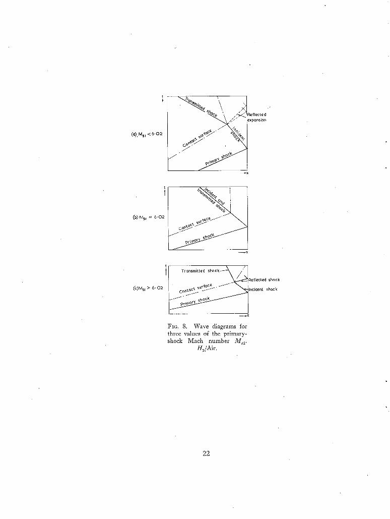
I t is seen f rom Fig. 3 that a s < a s for M81 < 6.02, and that a 2 > a s for Ms1 > 6.02. Thus , as
indicated in Figs. 4 and 5, a shock will be reflected f rom the contact surface for M., 1 > 6.02, and
an expansion wave will be reflected for Ms1 < 6.02. Wave diagrams for the two cases will thus be like those sketched in Fig. 8.
2.4.1. Reflections from the end of the tube. T h e pressure change at the nozzle entry associated
with the disturbance corresponds to the pressure ratio, Psa (see Fig. 2), when the disturbance is
reflected f rom the end of the tube. Assuming again that the end of the tube is effectively closed, the pressure ratio across the reflected shock is given by
P6~(~ + 2) - 1 - ( 2 6 ) Ps.~ PG5 +
Similarly, if an expansion wave strikes the end of the tube, the pressure ratio is given by
PsJ = 2P6J 3 - 1. (27)
By the use of Equations (9), (26) and (27), the overall pressure ratios resulting from reflection at the
end of the tube of the disturbances originating at the contact surface have been calculated. The
results are plotted against primary2shock Mach number in Fig. 5 which shows, for example, that
the disturbance to the static pressure is less than + 10 per cent when 5.7 < J3//,1 < 6.3.
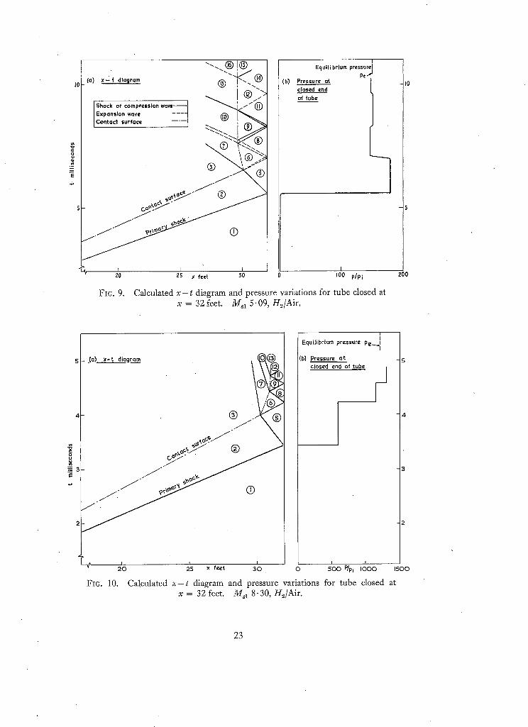
2.4.2. Multiple reflections and equilibrium contact-surface operation. After reflection from the
end of the tube, the disturbance originating from the interaction of the reflected primary shock and the contact surface will again strike the contact surface. A further reflected disturbanc'e will then
arise, and the original process will be repeated to give a multiple wave reflection between the end of the tube and the contact surface. Examples of the calculated wave patterns are reproduced in Figs. 9 and 10 which correspond respectively to primary-shock Mach numbers below and above the
'tailored' value. A wave-speed camera photograph showing the reflection process may be found
in Ref. 4. For the conditions of Fig. 9 it is seen that the disturbances reflected from the contact surface are
alternately expansion and compression waves, but that the contact surface is soon brought
substantially to rest. After the first reflected expansion, the reflected disturbances are seen to be
weak so that the pressure lies close to the 'equilibrium' pressure e p~. This is defined as the pressure
that would be reached if the flow behind the contact surface was brought to rest by the first
transmitted shock S~ (Fig. 2), and is given by the equation
(po3-1) + 1) -1/2 = ":'. (28) a3
It is very close to the pressure that would be reached if the flow were brought to rest in the second
instead of the first transmitted disturbance. In Fig. 10, for a shock Mach number above the 'tailored' value, the contact surface is again
brought effectively to rest rapidly, and, after the first reflected shock, the reflected disturbances
are weak and the pressure approximates to the 'equilibrium' value. As far as the solution has been
carried in Fig. 10, the reflected disturbances are shocks, but it appears from a comparison with p,
that weak expansions will be reflected from the contact surface at a later stage. Such expansion
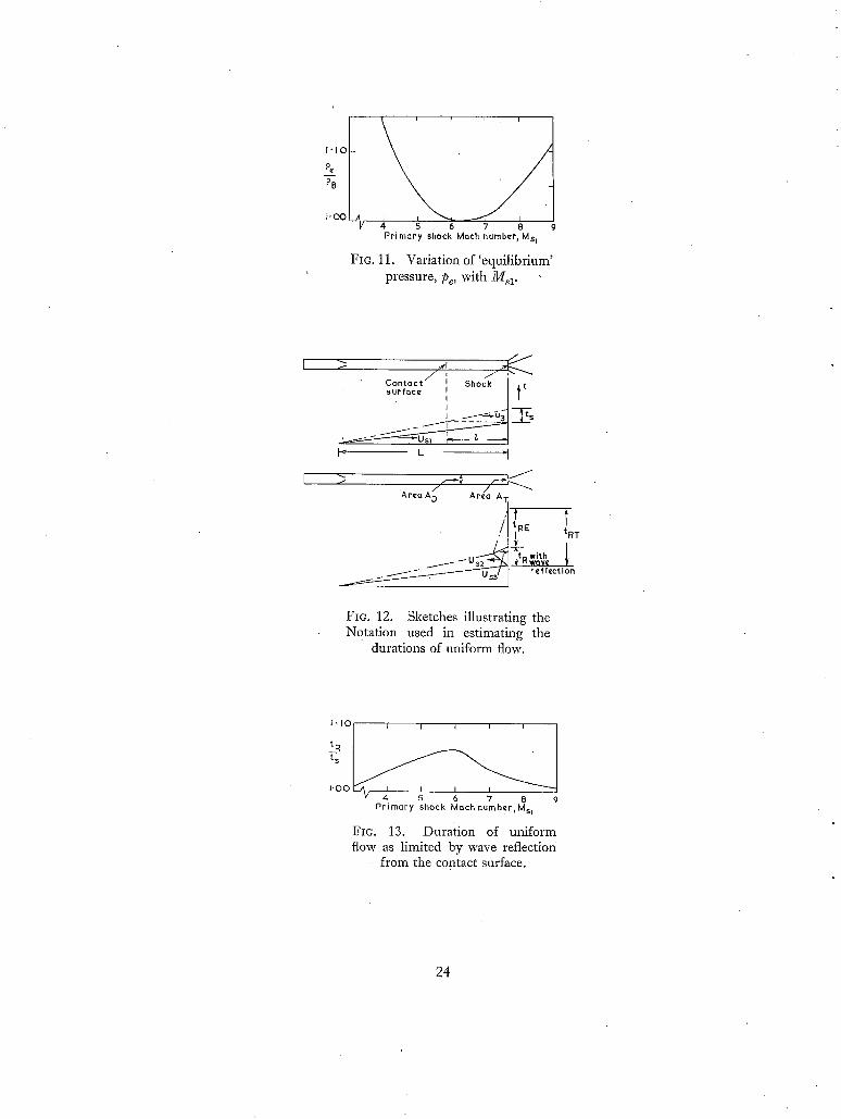
waves are found in a more detailed wave diagram included in Ref. 5. The ratio of the equilibrium pressure computed from Equation (28) to the pressure Ps after the
first reflected disturbance is plotted against primary-shock Mach number in Fig. 11. It is seen that
Ps is within 10 per cent of p, for a wide range of shock Mach number. In other words, after the arrival of the first reflected disturbance, the pressure at the end of the tube would be expected to
remain constant t0 within 10 per cent: This suggests that if the flow after the first disturbance is used to supply the nozzle, tile advantages of 'tailored' operation may be achieved over a much wider range of shock Mach number than that for which 'tailoring' is effectively achieved (see Section 2.4.1). The use of equilibrium contact-surface operation resembles the method of operation
e This expression follows the terminology of Ref. 5, where the use of the quasi-uniform flow after the contact surface has been brought effectively to rest by multiple wave retlections is termed 'equilibrium interface' operation.
7
employed in a gun tunnel where the piston is brought to rest by multiple shock compression, but
in a shock tunnel the reflected waves become weak more rapidly because of the different boundary condition at tile reflecting surface.
2.5. The Duration of Uniform Flow." For a 'straight-through' shock tunnel, the duration t, of uniform flow at the nozzle entry is given with the notation of Figs. 2 and 12 by
1 t~ = - ( 2 9 )
where
l= L(,_
and L is the channel length between the diaphragm and the nozzle entry. If the reflected-shock
technique is used at the shock Mach number for which there is no reflected disturbance from the
contact surface, the duration of uniform flow is the value tRT shown in Fig. 12. This time is
determined partly by the velocity u 3 of the contact surface before it meets the shock reflected from
the end of the tube, and partly by the velocity uc.8. after interaction with the reflected shock. This latter velocity is determined by the rate of mass flow into the nozzle throat, and would, as indicated in Section 2.4.1, be zero if the end of the tube were closed. By equating the rate of change of mass
in the.driving tube between the contact surface and the end of the tube with the rate of mass flow into the nozzle, we obtain from perfect-gas theory
[ 2 \~!~ AT = a s A D , (30)
where A~, is the cross-sectional area of the nozzle throat, and A D is that of the driving tube. It then follows from the geometry of Fig. 12, and from Equation (29), that
+ 1 , a t 1 . (31)
Inserting the numerical values for the 'tailored' shock Mach number, this equation becomes
t±er - 0.62 A1) ts" ~ + 0"7.
Since AD/A ~, is, typically, between 30 and 300 for a hypersonic sl{ock tunnel, it is sufficiently accurate to write this equation as
t±~, ~ 0" 62 AD t-~-,. AT (32)
Calculations in which allowance is made for real-gas effects on the mass flow into the nozzle entry are discussed in Appendix I. When 'real-gas' effects are included, it appears that a reasonable approximation (see Fig. 28) to the flow duration limited by the arrival of'the contact surface is
tR ~ 0-8 AD • t~. ~ A ~ (33 )
for shock Mach numbers within the range 4 to 9.
As far as the limitation imposed by the arrival of the contact surface is concerned, a large increase of running time is,-therefore, possible by using the reflected-shock technique at the 'tailored'
condition. For shock Mach numbers outside the range in which the disturbance reflected from the
contact surface is tolerable, the duration of uniform flow which starts when the primary shock strikes the end of the tube is limited by the arrival of the disturbance at the nozzle entry. Consideration
of Figs. 2 and 12 then shows that
= I-3/G I+ I.dG31 (34) I + 1
Values of this ratio are plotted against primary-shock Mach number in Fig. 13 where they are seen to be close to unity. There is, therefore, little gain over the flow duration in a 'straight-through' tube by using the flow in an 'untailored' reflected tube between the primary shock and the first reflected
disturbance. On the other hand, the flow duration with equilibrium contact-surface operation (see Section
2.4.2) will be of the order indicated by Equation (33) over a relatively wide range of shock Mach number. Moreover, it is possible that the flow in the driving tube between the arrival of the primary
shock at the nozzle entry and the achievement of 'equilibrium' conditions may be used in establishing
the flow in the nozzle and past the model under test.
2.5.1. The effects of the expansion wave from the primary diaphragm. It has been indicated above
that the limitation to the uniform driving flow imposed in a reflected-shock tunnel by the arrival of
the contact surface at the nozzle entry is unlikely to be severe; in many cases, an earlier limit will
be imposed by the arrival at the nozzle entry of the expansion wave originating when the primary
diaphragm ruptures. The tail of this wave moves to the right with velocity (u 8 - a3), and the head to the
left with velocitya 4. The head is reflected from the closed end of the driving chamber, and moves
back along the channel where it eventually reaches the nozzle entry. If we assume that the proportions of the tube are adjusted for each shock Mach number so that
the reflected head and tail arrive simultaneously at the nozzle entry, the results of Fig. 14 are obtained% This shows values of the flow duration for 'tailored' and equilibrium contact-surface operation as limited by the arrival of the expansion wave. The values are expressed in terms of the flow duration limited by the arrival of the contact surface in a 'straight-through' tube. It is seen that running times long compared with a 'straight-through' tunnel are obtainable in a suitably- proportioned reflected-shock tunnel for low shock Mach numbers. The ratio of flow duration decreases rapidly with rising shock Mach number, however, and is only about 2 for a shock Mach number of 9. It should, however, be borne in mind that viscous effects on the motion of the contact surface will lead to 'straight-through' running times which are appreciably shorter than the values used in Fig. 14, whereas (see Section" 3.2) the observed motion of the expansion wave is in good agreement with theory. Also the uniform-flow duration at' the expanded working section will' be equal to the duration of uniform driving flow minus the starting time of the nozzle. For a 'straight- through' tunnel these two times are frequently nearly equal, so that the ratios of flow duration at the expanded working section will be considerably larger than those plotted in Fig. 14.
Since the diaphragm position cannot be adjusted continuously in practice, the results of Fig. 14 are of little practical interest. In reality, the uniform conditions will be limited by the arrival of the
h e a d or tail of the expansion wave or the contact surface at the nozzle entry, and the geometry and shock Mach number will determine which of these limits occurs first. T h e situation is
e For simplicity, the effects of the transmitted shock on the motion of the contact surface are ignored.
9
illustrated in Fig. 15a where the time of arrival at the nozzle entry after the primary shock of the
contact surface, and the head and tail of the expansion are shown in terms of the ratio L ' /L of the
chamber to the channel length, and the ratio AD/A T of the cross-sectional areas of the driving tube
and the nozzle throat. To make some allowance for viscous effects on the motion of the contact
surface, it has been assumed that the time between the arrival of the shock and undisturbed contact
surface at the nozzle entry is one half the value given by inviscid-flow theory.
It is seen from Fig. 15a that there is a considerable advantage in using a large value of L'/L for
low shock Mach numbers, but that this is unnecessary at high shock Mach numbers. Under these
conditions it would, in practice, be highly undesirable to use a long chamber (large L') not only
because the hydrogen requirements and equilisation pressure would be increased, but because an
increase in L' will usually be accomplished at the expense of decreasing L, and hence reducing the
time before the arrival of the tail of the expansion wave. This point is illustrated more clearly in
Fig. 15b, where the value of L'/L giving maximum flow duration in a tube of fixed overall length (L + L') is shown.
These considerations suggest that there is a strong case for the provision of alternative diaphragm positions along a shock tunnel if the limitation to uniform flow duration imposed by the arrival of the expansion wave is to be minimised over a range of shock Mack number. For practical reasons it is difficult to provide a large number of diaphragm stations, and two are fitted to each of the N.P.L. shock tunnels.
An alternative approach is to eliminate the head or tail of the expansion wave. In theory 1 the tail
may be removed by placing a nozzle in the vicinity of the diaphragm in order to introduce a steady
expansion. Also, it is possible thfft the reflection of the head can be cancelled by suitable design of the closed end of the high-pressure chamber. Research on these possibilities is in hand at theN. P.L e
3. Experiments on the Performance of Reflected-Shock Tunnels. A considerable number of simplifying assumptions have been made in the analysis given above. In particular the fact that
viscous effects have been ignored would be expected (from, for example, the work reported in
Refs. 6 and 7) to have considerable effects on the motion of the contact surface, although these have
been minimised, where possible, by expressing the results for the reflected-shock tunnel in terms of those for the straight-through tunnel. Similarly, the assumption that the contact surface is plane
and thin may also give an inaccurate result for the strengths of the reflected and transmitted waves°
Moreover, the primary reflected shock, and subsequent reflected waves will, in practice, interact
with the boundary layer on the wall of the tribe, and their motion may thus be affected. In addition to neglecting these viscous effects, high-temperature real-gas effects have been ignored, and this will lead to increasing errors as the shock Mach number is raised.
To investigate the effects of these and other simplifying assumptions, experiments have been made in a small shock tube and a shock tunnel, and the results have been analysed using the theoretical predictions as a framework.
3.1. Details of the Apparatus and Measuring Tech~iques. Brief details of the apparatus and measuring techniques are given below.
The following paper, which has been prepared since the present Report was issued, may be consulted: D. L. Schultz . . . . A note on the use of steady expansions in shock tubes and shock
tunnels. A.R.C.C.P. 558. January, 1961.
10
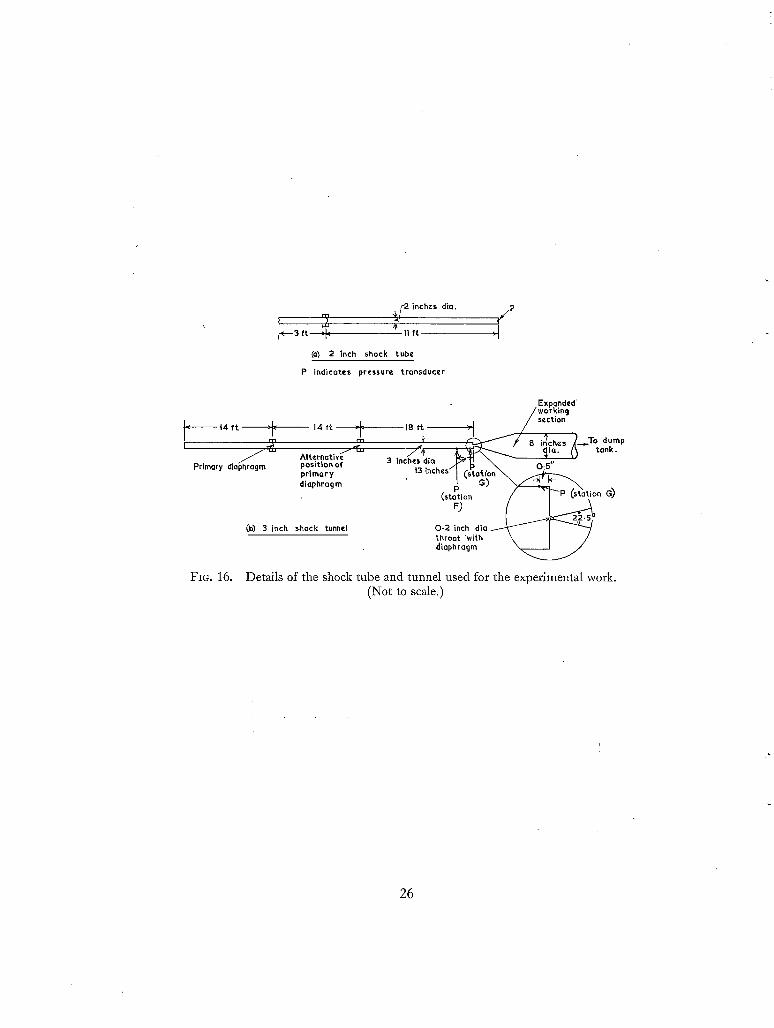
3.1.1. The shock tube and shock tunnel. The leading dimensions of the facilities used for the
experimental work are sketched in Fig. 16. The shock tube is that used for the ionisadon measure-
• ments reported in Ref. 8, and the shock tunnel is that used for the investigations of straight-through
operation described in Ref. 6. For the present work the nozzle entry of the shock tunnel was modified
to the form sketched in Fig. 16b for reflected-shock operation, and the diameter of the expanded
working section was reduced from 16 in. to 8 in. to give increased running time. Both tubes used
air as driven gas and hydrogen as driver gas; the maximum driver pressure was approximately 100
atmospheres, and the initial hydrogen temperature was atmospheric. A few runs were made with
nitrogen as driven gas to demonstrate that combustion at the contact surface did not affect the
results. The primary diaphragms were constructed of aluminium for most of the work, although Mylar was used for some low-pressure runs in the 2 in. diameter tube. Mylar was also used for the
nozzle diaphragm in the shock tunnel. Before the rupture of the nozzle diaphragm, the pressure in the
working section and dump tank of the shock tunnel was maintained at 5 microns of mercury absolute.
3.1.2. Measurement of the velocity of the primary shock. The passage of the primary shock was
detected by thin-film resistance thermometers mounted flush with the bores of the tubes. The
shock velocity was deduced from the time, required for the shock to pass between detectors located
1 ft. apart, as measured by a microsecond counter chronometer.
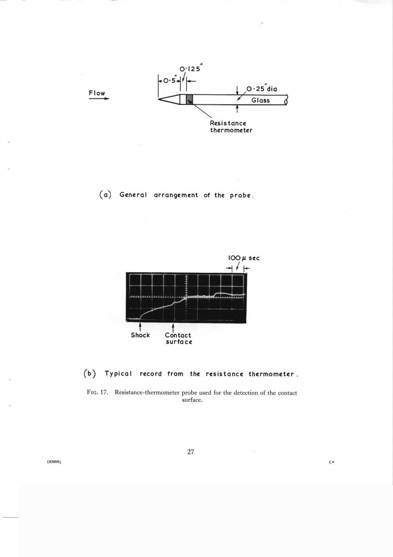
3.1.3. Detection of the contact surface. In the 2'in. diameter shock tube, the position of the contact
surface was detected by observing the output of a thin-film resistance thermometer located, as
shown in Fig. 17a, on a glass probe held on the axis of the tube. A typical record of the thin-film
output is reproduced in Fig. 17b, where the position of the contact surface is indicated. At this
point the heat-transfer rate as deduced from the surface temperature ceases to be constant as would
be expected from the turbulent character of the contact region. The approximately constant heat-
transfer rate up to the contact region is illustrated by the parabolic behaviour of surface temperature
with time.
3.1.4. _Pressure transducers. Pressure measurements were made at the centre of the closed end of
the 2 in. diameter shock tube as shown in Fig. 16a, and at the wall of the 3 in. diameter driving
tube of the shock tunnel at the stations G and F indicated in Fig. 16b. The transducers used were
SLM type PZ14 with quartz elements. Their nominal sensitivity is 4 pcb/lb sq in. and, with the
cable lengths normally employed, this results in an output signal of 20 mV/lb sq in. The natural
frequency is about 49 kc/sec and, since the transducers are sensitive to acceleration, it is necessary
to mount them in heavy supports isolated from the shock-tunnel structure. A suitable isolating compound has been found in a mixture* of equal parts of epoxy resin and a liquid polymer.
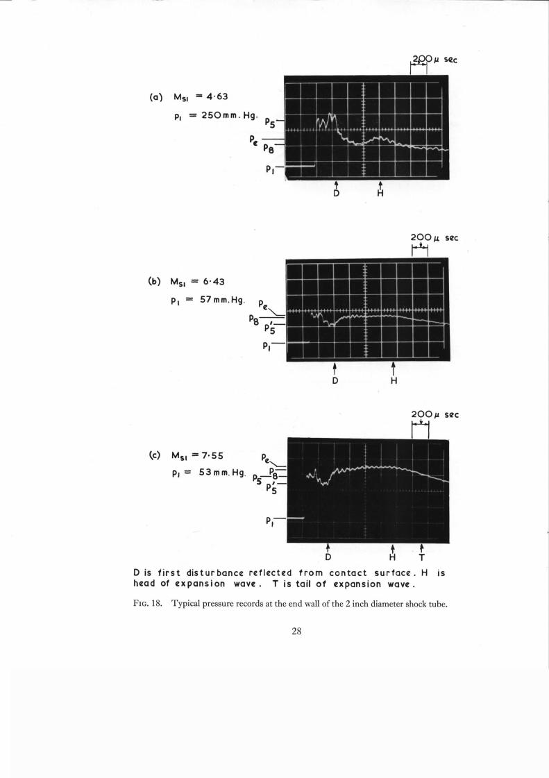
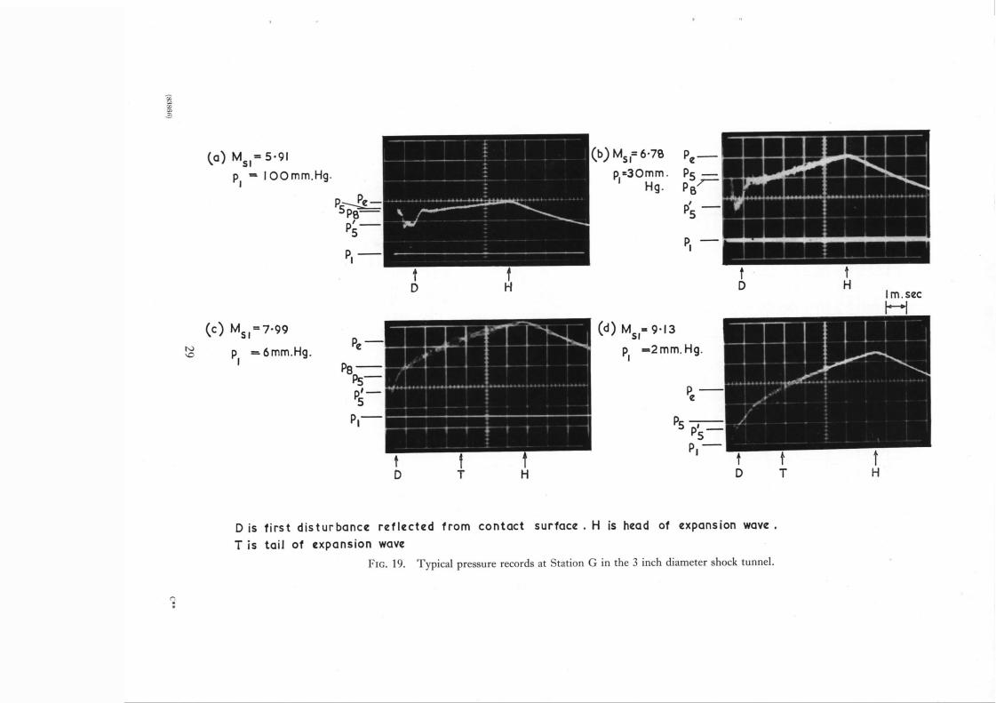
3.2. Discussion of the pressure records. Typical pressure records obtained in the 2 in. and 3 in. diameter tubes are reproduced in Figs. 18 and 19 respectively. The pressure rise immediately after
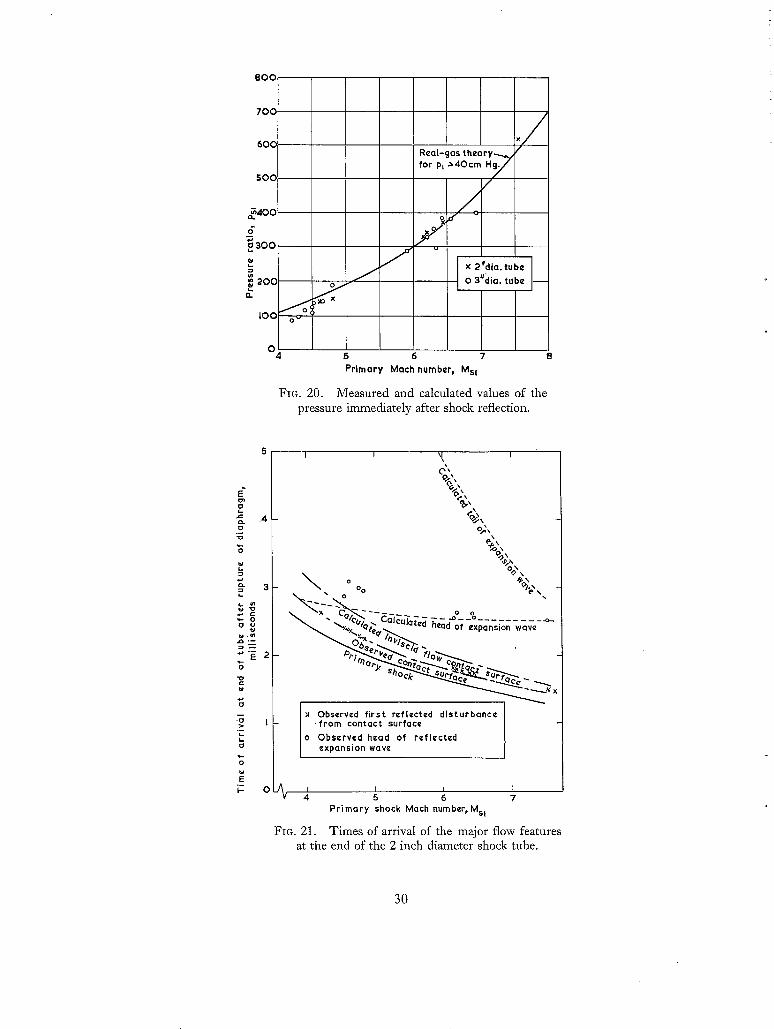
reflection of the shock is found to be in good agreement wiich real-gas theory as illustrated in Fig. 20,
the points on the traces interpreted as corresponding to P5 being indicated in Figs. 18 and 19. To enable the first disturbance reflected from the contact surface to be identified, it is necessary
to know the position of the contact surface. The results of the measurements made with the probe
described in Section 3.1.3 have been used to provide this information for the 2 in. tube, the results being slightly extrapolated to determine the time, after the arrival of the primary shock, at which the
contact surface would reach the end of the tube if it were uninfluenced by interaction with the
Araldite 103 and Thiokol Chemical Corporation liquid polymer L.P.3.
'11
reflected shock. It has been argued in Section 2.5 that this time will be slightly less than that after
which the first disturbance reflected from the contact surface arrives at the end wall. That this is observed in the experiments is demonstrated in Fig. 21. This diagram also includes curves for the
time of arrival of the contact surface according to inviscid-flow theory, and for the arrival of the tail and reflected head of the expansion wave originating at the diaphragm. It is seen that because of viscous effects on the motion of the contact surface, the time between the arrival of the shock
and contact surface is about one half the value predicted for inviscid flow. A similar result has been found in several previous investigations.
The agreement between the curve in Fig. 21 for the arrival of the contact surface and the observed
times of arrival of the first reflected disturbance suggests that the latter have been properly identified
in the pressure records, and the corresponding points are indicated on the traces reproduced in Fig. 18.
For the 3 in. tube, the position of the contact surface has not been measured in the present investigation, and the measurements made during previous experiments (e.g., Ref. 6) were used to establish its position. The corresponding points at which the first disturbance reflected from the contact surface would be expected to reach the pressure-measuring station are indicated in Fig. 19.
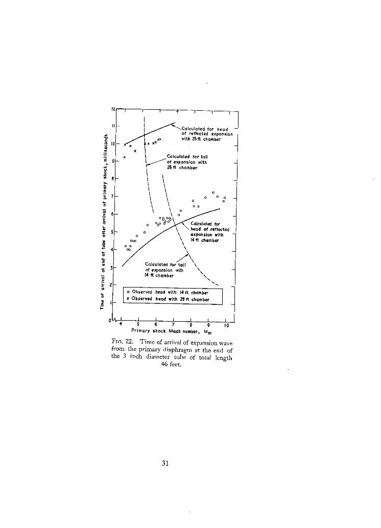
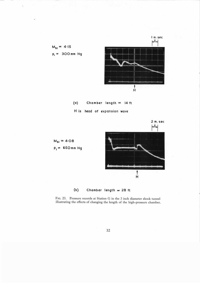
The pressure gradient associated with the arrival of the reflected head of the expansion wave is strong, and it is readily detected in the pressure records. Accordingly, it is possible to include experimental points in Figs. 21 and 22 where they are seen to be in reasonable agreement with calculation. The points taken to correspond with the arrival of the expansion head are indicated in the pressure records of Figs. 18 and 19. For the 3 in. diameter tube it was possible (see Fig. 16) to use alternative high-pressure chamber lengths of 14 ft and 28 ft. Pressure records illustrating the delay in the arrival of the expansion head produced by increase of chamber length are reproduced in Fig. 23, and the results are compared with theory in Fig. 22.
The pressure gradient associated with the arrival of the tail of the expansion wave is relatively
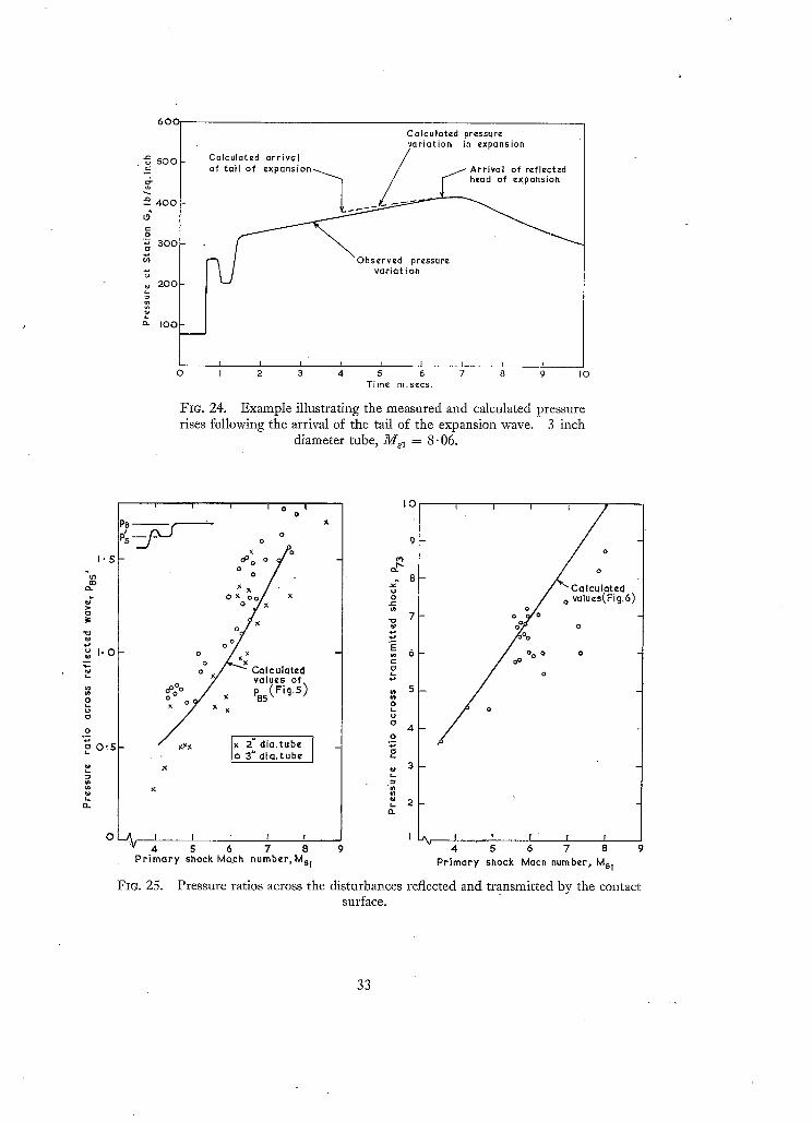
weak, and the expected increase of pressure with time is sometimes confused with the pressure rise associated with multiple reflections between the contact surface and the end of the tube. This is illustrated in Fig. 24, where a measured pressure record is compared with the pressure variation computed for the expansion wave. Because of the difficulty of identifying the time of arrival of the tail of the expansion wave, no experimental points are included in Figs. 21 and 22, but theoretical values are indicated on the pressure records of Figs. 18 and 19.
3.2.1. The fall of pressure immediately after the reflection of the primary shock. A feature of the pressure records not explained by any of the considerations included previously in the present paper is the fall of pressure measured near the end of the tube immediately after the reflection of the primary shock. Various explanations have been considered for this feature. It might, for example, arise from a fall of temperature by conduction to the walls of the tube, but this seems improbable because such an effect would be expected to persist to some extent throughout the pressure trace. The most plausible explanation is felt to lie in attenuation of the reflected shock produced by its interaction with the boundary layer formed on the wall of the tube after the passage of the primary shock. Quite severe attenuation has been ascribed 9 to this effect by Mark for shocks which were relatively weak compared with many of those used in the present investigation. Mark observed a pronounced Reynolds number effect, depending mainly on whether the boundary layer was laminar or turbulent in the region of interaction. In the present investigation, the Reynolds numbers were such that the
12

boundary layer would be expected to be turbulent except very near the end of the tube. No data are available on the effects of Reynolds number on the attenuation occurring with turbulent layers, and further research is required a t the higher pressures available in the new N.P.L. shock tunnels. Investigations are also required to explore the effects of the size and shape of the cross section of the tube.
It is possible that the pressure fall discussed here may preclude the use of the period immediately after shock reflection for test purposes, although, of course, this might be usefully employed in establishing the flow in the nozzle and past the model.
As far as the authors are aware this fall of pressure has not been reported previously by shock-tunnel users; it may have passed unnoticed, because it is only observed in the present experiments at points very close to the end of the tube.
3.2.2. Comparison of the strengths of the disturbances reflected and transmitted by the contact surface with the predictions of simple theory. The pressure ratio across the first disturbance reflected from the contact Surface has, as sketched in Fig. 25, been based on the pressure, Ps', immediately before the arrival of the disturbance. As discussed above, this pressure is less than the pressure, Ps, immediately after the reflection of the primary shock. Calculations suggest, however, that the strength of the disturbance reflected from the contact surface is not greatly affected by attenuation of the incident shock, although the strength of the transmitted shock is considerably reduced. These findings are, to some extent, borne out by experiment as illustrated in Fig. 25 where experimental observations are compared with the predictions of the simple theory of Section 2.4.
3.2.3. The pressures after the early disturbances reflected from the contact surface. The pressure records reproduced in Fig. 18 indicate that after the early disturbances reflected from the contact surface, the pressure settles down to an approximately uniform value, as predicted by calculations of the type illustrated in Figs. 9 and 10. As discussed previously, this quasi-uniform region is terminated by the arrival of the head of the expansion wave. In the 3 in. diameter tube (Figs. 19 and 23) the pressure also reaches an approximately uniform value at low shock Mach numbers, but a positive pressure gradient becomes increasingly pronounced as the shock Mach number is raised. Part of this pressure gradient is, however, associated with the pressure rise which follows the arrival of the tail of the expansion wave as illustrated, for example, in Fig. 24. It is possible that, if the arrival of the expansion tail could be delayed, the pressure would achieve a more constant value. Further research is, however, required to investigate this point.
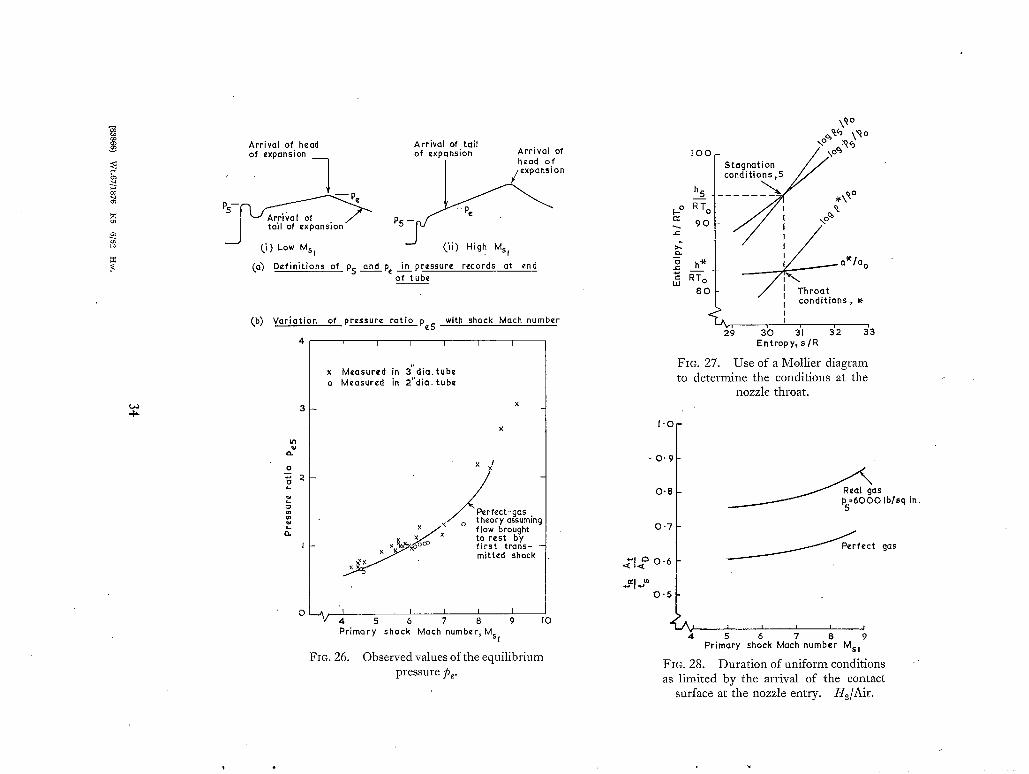
The 'equilibrium' pressure has been defined in the pressure records as illustrated in Fig. 26a, and values are compared with theory in Fig. 26b.
Concluding Remarks. The objects of the present investigation were to provide, on the basis of elementary theory, a broad framework for the analysis of the results o.f research on the performance of reflected-shock tunnels, and to obtain preliminary experimental results for comparison with the theoretical predictions. There is a reasonable measure of agreement between experiment and theory, and both suggest that substantial increases of flow duration may be achieved by using reflected- shock operation. It is, however, clear that further research is required before the potentialities of reflected-shock tunnels can be fully understood. The topics most urgently requiring investigation are, in the authors' opinions as follows:
(i) The effects of Reynolds number and tube geometry on the interaction of the reflected shock with the boundary layer, with particular reference to the attenuation of the shock and the uniformity of the pressure near the end of the tube.
13
(ii) The multiple wave reflection process between the contact surface and the end of the tube, especially at shock Mach numbers above the 'tailored' value. This work should include pressure measurements at the end of the tube for cases where the effects of the expansion wave are eliminated or postponed.
(iii i Methods for postponing or eliminating the disturbances produced at the end of the tube by the arrival of the tail or reflected head of the expansion wave.
(iv) The variation of temperature close to the nozzle entry.
(v) Extensions of the theoretical treatment to include high-temperature real-gas effects.
It would be particularly useful if these investigations could be made at the high pressure levels typical of modern shock-tube practice.
Achnowledgement. P. S. Pusey, P. J. Peggs and R. F. Cash of the Aerodynamics Division, N.P.L., assisted with the experimental work.
14

U
G
Ms
P
7
3 = ( 1)
For suffices s e e Fig. 2.
L IST OF SYMBOLS
Speed of sound
Flow velocity
Shock velocity
Shock Mach number
Static pressure
Ratio of specific heats
y + l , ~ - 1
7 - 1 2~
'assumed constant)
15
No.
1
• REFERENCES
Au~or
C. E. Wittliff, M. R. Wilson and A. Hertzberg
2 B. D. Henshall and G. E. Gadd ..
Title, etc.
3 I . I . Glass
4 I . I . Glass, W. Martin and G. N. Patterson ..
The tailored-interface hypersonic shock tunnel.
J. Ae. Sci. Vol. 26. p. 219. 1959.
Factors affecting the performance of the nozzle of a hypersonic shock tunnel.
A.R.C.C.P. 293. February, 1956.
Shock tubes. University of Toronto, U T I A Review No. 12. 1958.
A. Hertzberg, H. S. Glick, W. E. Smith and W. Squire.
6 B.D. Henshall ..
A theoretical and experimental study of the shock tube.
University of Toronto, UTIA Report No. 2. 1953.
Modifications of the shock tube for the generation of hypersonic flow.
A.E.D.C. TN-55-15, March, 1955.
7 G . F . Anderson
Experimental results from the N.P.L. Hypersonic Shock Tunnel.
Hypersonic flow. p. 1. Butterworths. 1960.
8 D . L . Schultz
Shock tube testing times. J. Aero. Space Sci. Vol. 26. No. 3. pp. 184 to 5.
March, 1959.
9 H. Mark ..
10 S. Feldman
Shock-tube research at the N.P.L. on the properties of gases at high temperatures. Part I. Ionization measurements.
Hypersonic flow. p. 301. Butterworths. 1960.
The interaction of a reflected shock wave with the boundary layer in a shock tube.
Cornell University Report AFOSR-TN-57-345, AD 132-418. 1957.
Hypersonic gas dynamic charts for equilibrium air.
AVCO Research Laboratory Report. 1957.
1 6

APPENDIX
Real-Gas Effects on the Mass Flow into the 'Nozzle
Real-gas effects on the motion of the contact surface after it has been brought effectively to rest by wave reflections are determined, as in Section 2.5.1, by considering the rate of mass flow into the
nozzle. The point (distance l' from the nozzle entry) in the driver tube where the reflected shock meets the contact surface determines the mass, pj'AD, of heated air available for supplying the
nozzle. The rate of mass flow into the'nozzle is p'a'AT, where p* and a* are the density and velocity
at the nozzle throat. Neglecting nozzle starting losses, the duration of flow limited by the arrival of the contact surface in the nozzle is thus
_ Psl'AD tR p,aeAT.
The length l' is determined as in Section 2.5.1 from the velocities of the shocks and contact surface, and it remains to find p* and a*. This is done conveniently by the use of a Mollier diagram for
equilibrium air such as that computed 1° by Feldman. The technique is best illustrated by an example.
If we take P5 = 6000 lb/sq in. and Ms1 = 7.5 (corresponding to pl = 10.5 lb/sq in.), we find that the specific enthalpy h e corresponds to hs/R T O = 93.9. Here suffix 0 denotes normal atmospheric conditions. This point is located on the Mollier diagram as illustrated in Fig. 27. By interpolation
along the isentrope (sir = 30.5) through this point, the specific enthalpy at the nozzle throat is found at which the value of a* computed from the energy equation
a~ = V{2(h~-h*)}
agrees with the value deduced from the curves of constant a/a o. This procedure gives h*/R T O = 83.0
and a*/a o = 3- 83, so that a* = 4280 ft/sec. The value of P*/Po is also read from the Mollier diagram as 13.2, so that p* = 0.031 slugs/cu ft.
The values computed do not vary greatly with the pressure P5 over the range of practical interest in shock-tunnel operation, and the values of the flow duration plotted in Fig. 28 may be regarded as
typical. The values are expressed in terms of the running time for a straight-through shock tunnel
with the same channel length, and allowance should be made for viscous effects on the motion of the contact surface when using Fig. 28 to compute numerical values of the flow duration. Values computed from Equation (31) for a perfect gas are included in Fig. 28.
17 (s3sss) B
GO
By-pass tube
Driver /D~ aPhragm /tube
} ~ - - ~ 7 Duralion o, I i toce . / / ,P/uniform flow ~ ~ a t nozzle entry
~ x
FIG. la. A'straight-through' shock tunnel.
Duration of • ~ I /unilorm IIow / | at nozzle entry
%°, / L
o~Oc~-~_ ._. - _~
FIe. lb. A 'reflected-shock' shock tunnel (assuming no reflected disturbance from
the contact surface).
- - + ve velocity
. US¢~ ~ ~ u ~
o / ° s ~ - ~ I
'C--/7~ ® ' I
°.o i'o -:o o[o diaphragm nozzle entry
FIo. 2. Sketch il lustrating the Notation.
8 H2/AIR
.~__ Psz
/ f
I 2
/ / /
u3 / a 3 /
/ / / / / / /
fY J
.J J
/ f
/ / /
/ 2
o
o
o~3/ / / /
a53 / I /
/ /
/
3 4 5 6 7 8 9 Primary shock Maeh numbcr~ Msz
0 I0 I I
FIG. 3. Va lues of a23 , a~a , u~/a 3 and Psi.
19
8
7
~l~-C I
I g
"O, "10 .=--
I:k C:
O
H2/air
F m . ft.
Expansion
J j ~
J j - -
J J J 1 1
3 . 0
Velocities of the wave
- -Shock ~ ~ ¢ ' ) . ~ ' ~
~c USZlak~ /
I
J
f ~
4"0 ..K,O 6"0 7 ' 0 B'O Mach number of primary shock~ Ms1
incident on the contact surface and reflected and transmitted by it.
9"0
I
H 2/air
1 .4
o.
~a 1.3
tCr
1.2
I'O = .o
~o.9
~O-B
~, 0.7 n
J 3 . 0
FIG. 5.
' / , i
/
/< j / / /
z / 4.0 5.0 6"0 7.0 8"0
Mach number 0¢ primary shack~ Msl
Pressure ratio across the disturbance reflected from the contact surface.
9.0 I0.0
20
p. o .
O
E
O
.9
£
II HJair
IO
4
3
>
3 - 0
FIG. 6.
J J
J / /
/ /
/ /
/ /
/
4-0 5'O 6'O 7 ' 0 8"0 9 . 0 Math number o~ primary shock, Msz
Pressure ratio across the shock transmitted by the contact surface.
3
÷ ¢q o
• "-~ m 2 _~°
g ! , °
2~
L¢I
H 2/AI R
Transmitted shock f
f
l J f ~" C O -
-'~ 3.0 4 ' 0 5"0 / 6 0 7-O 8.0 c£C J Primary shock. Mach n-rnbcr~ Msl
-I
The contact-surface velocity, and the Mach numbers of the reflected and transmitted shocks.
FIG. 7.
2
i
o
° 5
21
(o), Msl < 6 . 0 2
(b) Mst = 6 . 0 2
i :
~)Msr> 6.02
/ ,~o~)J l
~ X
e ~ % '
" ~ i " o ~
s.dac~/"
Transmitted shock .~
~ X
FIO. 8. Wave diagrams for three values of the primary- shock Mach number Ms1.
H2/Air.
~efl¢ctcd shock
ncid~n~, shock
22
"--.®!®
Shock or compression wove , ] :;% ~ ~ > Expanslon wave . . . . J Contact surface j
(o) x Z t dla(jrum
/ - @
20 Z5 x feet 30
Fro. 9.
(b)
Equilibrium pressurel pc . - 1
Pressure ot closed end
of tube
L_ I00 P/Pi
Calculated x - t diagram and pressure variations for tube closed at x = 32 feet. M81 5' 09, H2/Air.
200
.(a) x-t diagram
j .
J " 9
F I G . 10 .
® . J
c.,~b--""
(!)
1 Equilibrium pressure Pe~ l I
(b) Pressure at closed end of tube 1
[
25 x feet 3 0 0 5 P/Pl I 0 0 0 1 5 0 0
Calculated x - t diagram and pressure variations for tube closed at x = 32 feet. Msz 8.30, H2/Air.
23
I-IO Pe P8
t.OO
i i i i
~/ 4 5 6 7 B 9 Pr imary shock Math number, Msl
FIC. 11. Variation of 'equilibrium' pressure, Pc, with M81.
/ , j ,-.---- • Contact I Shock t
' surface I
A rea A D Area AT,
'-m'~t, with J
reflection
Fro. 12. Sketches illustrating the Notation used in estimating the
durations of uniform flow.
"°1 ' ' ' ' ' I
I'OO
Primary shock Machnumber, Msl
FIG. 13. Durat ion of uniform flow as limited by wave reflection
from the contact surface.
24

~n
_ ',
............ ~:: ~
\ \ Ex-onsion . ~ i . u r l o c ¢ / _ . ~
\ /
t s Flow du ra t i on for "s t ra igh t - th rough"opera t ion
tRE F l o w d u r a t i o n f a r ' e q u i l i b r i u m c o n t a c t - s u r f a c e " o p e r a t i o n
tRT Flow durat ion f a r ' t a i l o r e d ' ' ope ra t i on
2 5
tRE ts
20
15
lO
5
0 _
I i i i
1 tRE
"<L_ / I I f S 6 7 8
M s I
FIO. 14. Limitation to t h e uniform flow imposed by the arrival of the expansion wave.
H2/Air.
E
u~
E
"7"
10.0 I (,a) L and L' adjusted ind___.ependently
I ~ Diaph ragrn
s - 0 1 - J L I- L' ~I-// L
4.0 F \ ~ i r / "~/""
~ 1 0 0
o
_J
\
I'0 ClL~-0 \ . -~.~___.
0"4
0'3 ~ " ~ ~ " \ \
0'2 " /L =02~. _._-. -----" - - - " " ~ " . .
O ' J _ . . ~ . - ~
0-05 : / ' : o z . ~ " f " 0.04 - _ . / ~ Cootaot . r , a . 0,03 - / . . . . . Head of expansion
. . . . . . Tail of expanslon 0'0~
F l igh t Math number - B I0 12 14 16
0 " 0 1 I I I , I . I
4 ~ ~ ~ Ms, 8
3 ~ ( b ) Wi th (L+ L ' ) cons tan t
0 I I I F-- I 5 6 7 8 9 Msl
FIG. 15. L imi t a t i ons to the u n i f o r m cond i t ions at the nozzle en t ry imposed b y the arr ival of the con tac t surface and the tail and ref lected head of the
expans ion wave.
~ -2 inches dio. / p
l i f t ~J
~) 2 lnch shock tube
P indicates pressure transducer
~t 14 ft ~
Primary diaphragm
Expanded' /work'm 9
~L 18 ft "J / section 14 f t -r
Altcrnativ~ ~ ~ i ~ . . _ ~ T o (lump . / ~ . L : ~ i°" 0 tonk. posmonof a inches o,o r f ~ ~ pr,m°ry '3 diaphragm i ~ G) xN~_____~.t~-
CStOt'O. / " ~ P Cs£'alio. G)
(b) 3 inch shock tunnel 0 . 2 inch dia ~ J throat "with \ I / ~ttophragrn
FIG. 16. Details of the shock tube and tunnel used for the experimental work. (Not to scale.)
26
Flow
0"125"
t-/ °~1 P- ~,o .-0:o
~ t Resis tance thermometer
(a ) General arrangement of the probe.
lOOp sec
t t Shock Contact
surfa ce
('b) Typ ica l record from the resistance thermometer .
FIG. 17. Resistance-thermometer probe used for the detection of the contact surface.
27 (83866) C*
~.~O# sec
(a) Msl " 4"63
Pl = 2 5 0 m m . Hg.
D
200 ~ sec
(b) Msl = 6"43
Pl "" 57mm.Hg.
f D
t H
(~c) Msl = 7 .55
PI = 53 ram. Hg.
200 # sec
D H T
D is f i r s t d i s t u r b a n c e re f lec ted f r o m c o n t a c t s u r f a c e . H head of e x p a n s i o n wave. T is ta i l o f expans ion wave.
is
Fzo. 18. Typical pressure records at the end wall of the 2 inch diameter shock tube.
28
(a) Msl = S.91 Pl " IOOmm.Hg.
(c) Ms1=7-99
Pl == 6mm.Hg. Ps~
Pl"
(b) Ms~ 6.7B Pl=3Omm.
Hg.
Pe
Ps ; - : PS'
I
P5
t f t D H D
(d) Msl= 9.13 Pl -2mm.Hg
Pl t t '~ t D T H D
t T
t H
I m. S¢C
t H
Dis f i rs t disturbance ref lected from contact surface. H is head of expansion wave. T is tai l of expansion wave
FIG. 19. Typical pressure records at Station G in the 3 inch diameter shock tunnel.
800
70C
60C
50,
~ 4 0 0
o" o- 3 0 0
.=
~, 2 o c P n
IOC
/
04 5
Pr imary
/
Real-gas theory ~..=/ for Pl ~ 4 0 c m / ~
/o
/
x 2qdia.tube _ _ 0 3"dia. tube
7 B Math number, Msi
FIG. 20. Measured and calculated values of the pressure immediately after shock reflection.
E" o
Jc .4 o. o "o
3 L.
~- 0 u
.wO , -
"~'~_ 2
• >o t L t .
i= o
I I ~ , / I
0/~,
°*;-'o2~, o-3~
o,a,
o;, %,
O. \ \ °% °~o,,
" - ~ ° % , . oa of e x p g ~ C o g - ~ ; ~ a -
l',j ~"Z:ZLt~;'>:~_ e o ~ , _
" ~o¢~--~.~;t;~,/~,-~.,_.
:~ Observed f i r s t reflected d is turbance J • f rom contact surface J
o Observed head of ref lected expansion Wave j
~/ f I I f 4 5 6 7
Pr imary shock Mach number, Ms!
FIG. 21. Times of arrival of the major flow features at the end of the 2 inch diameter shock tube.
30
12
o I( e l =
E
k 7
S
,4
o
o
I -
I Calculated lot head
J / ' ~ ' / " ~ o t " reflected expansion I J i x x x~ with 28fl chamber
x I x I Calculated for tail
t ~ o f expansion wlth E8 fl chamber I
~ ° o ~ o o o
o 8~o ~ ~ , , . , ~ o ~ \ o %0 ~ ' a ~ ¢ . ~ Calculated for
J \ \ head of reflected o o / \ expansion with
ooo \ 14 ff chamber o o / \ \ 14 ff chamber
/ Calculated for"~tail \ \ of expansion with \ 14 f( chamber \ \
o Observed head with 14 ft chamber x Observed head with 28 ft chamber
L~ I I I I I I I d 5 6 7 8 9 I0
Primary shock Mach number, Msl
FIG. 22. Time of arrival of expansion wave from the primary diaphragm at the end of the 3 inch diameter tube of total length
46 feet.
31
Msl -" 4"15
p ,= 3 0 0 m m Hg
I m . SRC
¢1
t H
(o) Chamber length = 14f t
H is head of expansion wave
2 Il l . SeC
Msl = 4 . 0 8
Pl =" 6 S O m m H g
t H
(b) Chamber length -- 28 f t
FIG. 23. Pressure records at Station G in the 3 inch diameter shock tunnel illustrating the effects of changing the length of the high-pressure chamber.
32
60C
"~ 5oo ._
4 0 0 d
3 0 0
2 0 0
L
o. I00
Calculated pressure variation in expansion
Calculated arr ival /
I U variation
T I 1 1 I 1 I [ J~
0 I 2 3 4 5 6 7 8 9 lO Ti me m.secs.
FIG. 24. Example illustrating the measured and calculated pressure rises following the arrival of the tail of the expansion wave. 3 inch
diameter tube, M,1 = 8" 06.
I - 5
o ~
. a
~ l - o
o
.£ . J
? 0~5
( 3 .
t I I I 0 0 |
P s - - p;_ J o o
~ i ] i t ° x oo x,.
o ° ° x o K
o ed values of
2i/;;;iii i x
IO
9 t~
. 8 o
7
6 c 1:/
o
u o 4 o 0
3
2
i ( i i o / ~ l ~ , , ~ t e d
o / o values(Fig,6) o o
o o
%
o o o o o o
I 1 i I I 1 r I ! :}v 4 5 6 7 8 4 5 6 7 8
Primary shock Ma.ch number, Msl Primary shock Mach number, Ms!
F I G . 25 . Pressure ratios across the disturbances reflected and transmitted by the contact surface.
33
o'}
Arrival of head Arrival of tail of expansion _ _ of expansion Arrival of
P5-- ~ - -Pc p 5 _ _ ~ _ _ ~ , ~.~. J ('ii) High MSl (,)} Low Msl
Ca) Definitions of P5 and Pe i._.n_n pressure records at end of tube
(b) yariation
13.
0
2 o
?
Z ( 3 .
I
of pressure ratio Pc5 with shock Mach number
B I I 1
x Measured in 3"dia.tube o Measured in 2"dia. tube
I ]
~ t P ~ r f¢ct- g as . o theory assumln!
flow brought to rest by f irst trans- mitted shock
x "<
I I I I I V s ~ ~ 8 9 ,o
Primary shock Mach number, Ms!
FIO. 26. Observed values of the equilibrium pressure Pe"
~ O
o ~ \'~o I o o / / / j \ o~R~
Stagnation conditions ,S ~ , ¢
/ ! Throat I I H- -..--. I~s , ~" i
29 3b 3'I 3'2 3'3 Entropy, s/R
Fie. 27. Use of a Mollier diagram to determine the conditions at the
nozzle throat.
h5 ~o ~-9 o r e
9O
,2
o h ~
80
I-0
-0-9
0-8
0-7
• ~ 1 ~ o-~
~ 1 ~ 0"5
a s
O Ib/sq in.
~ ' ~ P e r f ¢ c t gas
5 6 7 8 9 Primary shock Mach number Msl
FIG. 28. Duration of uniform conditions as limited by the arrival of the contact
surface at the nozzle entry. HJAir.
Publications of the AeronauticalResearch Council
x942 Vol. Vol.
x943 Vol. Vol.
x944 Vol. Vol.
I945 Vol. Vol. Vol.
Vol.
x946 Vol. Vol.
Vol.
x947 Vol. Vol.
x948 Vol.
Vol.
Special VoL
Vol.
Vol.
ANNUAL TECHNICAL REPORTS OF THE AERONAUTICAL RESEARCH COUNCIL (BOUND VOLUMES)
I. Aero and Hydrodynamics, Aerofoils, Airscrews, Engines. 75s. (post 2s. 9d.) II. Noise, Parachutes, Stability and Control, Structures, Vibration, Wind Tunnels. 47s. 6d. (post 2s. 3d.)
I. Aerodynamics, Aerofoils, Airscrews. 8os. (post 2s. 6d.) II. Engines, Flutter, Materials, Parachutes, Performance, Stability and Control, Structures.
9os. (post 2s. 9d.) I. Aero and Hydrodynamics, Aerofoils, Aircraft, Airscrews, Controls. 84s. (post 3s.)
n . Flutter and Vibration, Materials, Miscellaneous, Navigation, Parachutes, Performance, Plates and Panels, Stability, Structures, Test Equipment, Wind Tunnels. 84s. (post 3s.)
I. Aero and Hydrodynamics, Aerofoils. I3OS. (post 3s. 6d.) II. Aircraft, Airscrews, Controls. I3os. (post 3s. 6d.)
III. Flutter and Vibration, Instruments, Miscellaneous, Parachutes, Plates and Panels, Propulsion. i3os. (post 3s. 3d.)
IV. Stability, Structures, Wind Tunnels, Wind Tunnel Technique. x3os. (post 3s. 3d.)
I. Accidents, Aerodynamics, Aerofoils and Hydrofoils. 168s. (post 3s. 9d.) II. Airscrews, Cabin Cooling, Chemical Hazards, Controls, Flames, Flutter, Helicopters, Instruments and
Instrumentation, Interference, Jets, Miscellaneous, Parachutes. ,i68s. (post 3s. 3d.) III. Performance, Propulsion, Seaplanes, Stability, Structures, Wind Tunnels. i68s. (post 3s. 6d.)
I. Aerodynamics, Aerofoils, Aircraft. i68s. (post 3s. 9d.) II. Airscrews and Rotors, Controls, Flutter, Materials, Miscellaneous, Parachutes, Propulsion, Seaplanes,
Stability, Structures, Take-off and Landing. i68s. (post 3s. 9d.)
I. Aerodynamics, Aerofoils, Aircraft, Airsarews, Controls, Flutter and Vibration, Helicopters, Instruments, Propulsion, Seaplane, Stability, Structures, Wind Tunnels. I3os. (post 3s. 3d.)
II. Aerodynamics, Aerofoils, Aircraft, Airscrews, Controls, Flutter and Vibration, Helicopters, Instruments, Propulsion, Seaplane, Stability, Structures, Wind Tunnels. i los. (post 3s. 3d.)
Volumes I. Aero and Hydrodynamics, Aerofoils, Controls, Flutter, Kites, Parachutes, Performance, Propulsion,
Stability. I26S. (post 3s.) II. Aero and Hydrodynamics, Aerofoils, Airscrews, Controls, Flutter, Materials, Miscellaneous, Parachutes,
Propulsion, Stability, Structures. I47s. (post 3s.) III. Aero and Hydrodynamics, Aerofoils, Airscrews, Controls, Flutter, Kites, Miscellaneous, Parachutes,
Propulsion, Seaplanes, Stability, Structures, Test Equipment. i89s. (post 3s. 9d.)
Reviews of the Aeronautical Research Council z939-48 3s. (post 6d.) 1949-54 5s. (post 5d.)
Index to all Reports and Memoranda published in the Annual Technical Reports 19o9-1947 R. & M. 2600 (out of print)
Indexes to the Reports and Memoranda of the Aeronautical Research Council Between Nos. 2351-2449 R. & M. No. 245o 2s. (post 3d.) Between Nos. 2451-2549 Between Nos. 2551-2649 Between Nos. 2651-2749 Between Nos. 2751-2849 Between Nos; 2851-2949 Between Nos. 2951-3o49 Between Nos. 3o51-3149
R. & M. No. 2550 2s. 6d. (post 3d.) R. & M. No. 2650 2s. 6d. (post 3d.) R. & M. No. 275o 2s. 6d. (post 3d.) R. & M. No. 285o 2s. 6d. (post 3d.) R. & M. No. 295o 3s. (post 3d.) R. & M. No. 3o5o 3s. 6d. (post 3d.) R. & M. No. 315o 3s. 6d. (post 3d.)
HER MAJESTY'S STATIONERY OFFICE from the addresses overleaf

~o & Mo No. 3265
© Crown copyright I96Z
Printed and published by HER MAJESTY'S STATIONERY OFFICE
To be purchased from York House, Kingsway, London w.c.2
423 Oxford Street, London w.I I3A Castle Street, Edinburgh 2
Io9 St. Mary Street, Cardiff 39 King Street, Manchester 2
5o Fairfax Street, Bristol I 35 Smallbrook, Ringway, Birmingham 5
8o Chichester Street, Belfast I or through any bookseller
Printed in England
~o & Mo No, 3265
S.O. Code No. 23-3265