Embed Size (px)
Citation preview
18th
Plansee Seminar HM 66/1
On the Formation of Precipitations in Highly (Cr,V)-doped
Cemented Carbides
Ch. Toufar*, W.D. Schubert*, M. Hashiya**, Y. Kubo**
* Institute of Chemical Technologies and Analytics, Vienna University of Technology, A-1060 Vienna,
Getreidemarkt 9, Austria;
** Hitachi Tool Engineering, Ltd., Narita, Japan.
Abstract
In order to minimize WC grain growth during liquid-phase sintering of cemented carbides growth
inhibitors are added to the respective powder formulations. With decreasing particle size of WC powders
(submicron → ultrafine → near-nano) the demand for higher inhibitor additions, in particular additions of
vanadium and chromium grows. With increasing amount of growth inhibitors added the respective limits
of solubility are achieved in the binder and both, Cr- and/or V-containing phases form on subsequent
cooling.
This work describes the nature and size of such precipitations and demonstrates that at a given (Cr+V)
to Co ratio the size of the precipitates varies significantly with the amount of cobalt from nano-sized
(< 100 nm) to micro-sized (0.1 to 2 µm) and finally macro*-sized (> 2 to 20 µm) precipitations.
* The term macro is used here for the size of precipitations which are readily visible in the optical microscope.
Keywords
WC, grain growth inhibition, near-nano grades, inhibitor precipitations
Introduction
In the past years a trend in the hardmetal industry towards producing finer and finer grained hardmetals
has occurred, as decreasing the WC grain size is an effective way to improve their hardness and
strength while still retaining a moderate toughness. This has put high demands on the manufacturing
industries for both, the starting WC powders and the sintered materials.
One of the crucial aspects in fine-grained hardmetal production is the tendency of very fine WC-grains to
coarsen during sintering. This happens due to their high interface free energies as well as distinct
differences in individual grain sizes (size distributions) which act as driving forces. To restrict unwanted
coarsening and to accomplish ultrafine microstructures in the sintered alloy, grain growth inhibitors are
18th
Plansee Seminar HM 66/2
commonly added. Usually chromium carbide, vanadium carbide, or mixtures of both carbides are used
for this purpose [1].
Grain growth inhibition in hardmetals is governed by the amount of inhibitor carbide in relation to the
amount of binder. Hayashi et al. [2] showed, that there is a limit at which no further suppression of grain
growth occurs, even when the amount of inhibitor carbide is increased. This limit depends on the
chemical nature of the inhibitor and represents its maximum solubility in the liquid binder at a given
sintering temperature.
During cooling the formation of precipitations can occur which strongly depends upon the kind and
amount of inhibitor added. For example a significant amount of chromium is soluble in cobalt even at
room temperature, whereas the quantity of vanadium in Co in the cooled-down conditions is only
marginal. Therefore precipitations of (V,W)C1-X will always form when vanadium is used as grain growth
inhibitor. This aspect has been widely examined [3-9]. Less is known about high chromium- [8] and
chromium/vanadium mixed additions, the nature and the size of precipitations, that are formed once the
solubility limit in the binder is reached.
Large inhibitor-containing precipitates have a negative impact on important characteristics of the
hardmetal such as bending strength or fracture toughness, in particular if the size of the precipitates
exceeds a certain critical size limit of about 6 µm [7,10].
In order to investigate the formation and size of Cr- and V-precipitations in hardmetals the amount of
cobalt binder, but not the binder to inhibitor ratio was modified starting from a standard alloy containing
10 wt% Co, 1 wt% Cr3C2 and 0.5 wt% VC. Therefore, the absolute amount of inhibitor carbide and also
the WC to inhibitor ratio changed, whereas the inhibitor content in weight relation to the amount of binder
remained the same. Apart from that each alloy was sintered in a carbon-saturated and a two-phase
variant to determine a dependence of the formation of precipitations on the carbon activity.
Experimental
Starting Materials
The WC powder used for this study was supplied by Wolfram Bergbau- und Hütten AG, Austria.
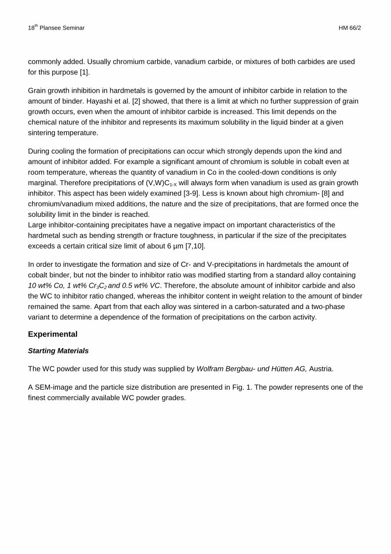
A SEM-image and the particle size distribution are presented in Fig. 1. The powder represents one of the
finest commercially available WC powder grades.
18th
Plansee Seminar HM 66/3
(a) (b)
Figure 1: SEM-image (a) and particle size distribution (b) of the starting WC powder (mean SEM particle size: ~150 nm)
Co powder was supplied by OMG (0.8 µm), Cr3C2 by H.C. Starck and VC1-X by Treibacher Industrie AG.
Alloy Preparation
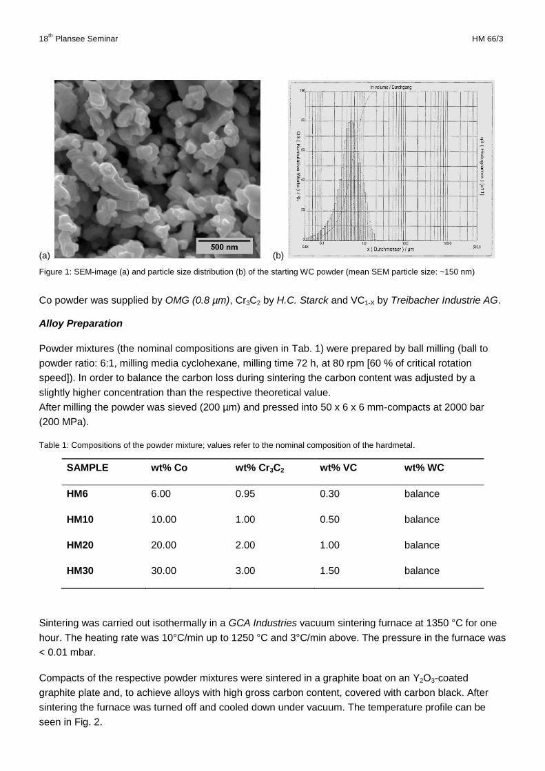
Powder mixtures (the nominal compositions are given in Tab. 1) were prepared by ball milling (ball to
powder ratio: 6:1, milling media cyclohexane, milling time 72 h, at 80 rpm [60 % of critical rotation
speed]). In order to balance the carbon loss during sintering the carbon content was adjusted by a
slightly higher concentration than the respective theoretical value.
After milling the powder was sieved (200 µm) and pressed into 50 x 6 x 6 mm-compacts at 2000 bar
(200 MPa).
Table 1: Compositions of the powder mixture; values refer to the nominal composition of the hardmetal.
SAMPLE wt% Co wt% Cr3C2 wt% VC wt% WC
HM6 6.00 0.95 0.30 balance
HM10 10.00 1.00 0.50 balance
HM20 20.00 2.00 1.00 balance
HM30 30.00 3.00 1.50 balance
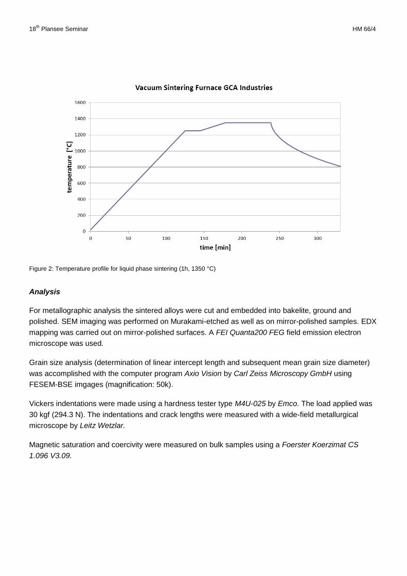
Sintering was carried out isothermally in a GCA Industries vacuum sintering furnace at 1350 °C for one
hour. The heating rate was 10°C/min up to 1250 °C and 3°C/min above. The pressure in the furnace was
< 0.01 mbar.
Compacts of the respective powder mixtures were sintered in a graphite boat on an Y2O3-coated
graphite plate and, to achieve alloys with high gross carbon content, covered with carbon black. After
sintering the furnace was turned off and cooled down under vacuum. The temperature profile can be
seen in Fig. 2.
18th
Plansee Seminar HM 66/4
Figure 2: Temperature profile for liquid phase sintering (1h, 1350 °C)
Analysis
For metallographic analysis the sintered alloys were cut and embedded into bakelite, ground and
polished. SEM imaging was performed on Murakami-etched as well as on mirror-polished samples. EDX
mapping was carried out on mirror-polished surfaces. A FEI Quanta200 FEG field emission electron
microscope was used.
Grain size analysis (determination of linear intercept length and subsequent mean grain size diameter)
was accomplished with the computer program Axio Vision by Carl Zeiss Microscopy GmbH using
FESEM-BSE imgages (magnification: 50k).
Vickers indentations were made using a hardness tester type M4U-025 by Emco. The load applied was
30 kgf (294.3 N). The indentations and crack lengths were measured with a wide-field metallurgical
microscope by Leitz Wetzlar.
Magnetic saturation and coercivity were measured on bulk samples using a Foerster Koerzimat CS
1.096 V3.09.
18th
Plansee Seminar HM 66/5
Results
Grain Growth and Microstructure
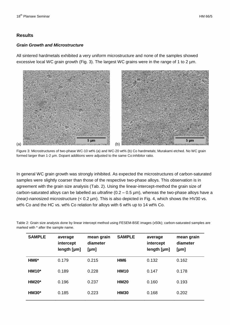
All sintered hardmetals exhibited a very uniform microstructure and none of the samples showed
excessive local WC grain growth (Fig. 3). The largest WC grains were in the range of 1 to 2 µm.
(a) (b)
Figure 3: Microstructures of two-phase WC-10 wt% (a) and WC-20 wt% (b) Co hardmetals; Murakami etched. No WC grain
formed larger than 1-2 µm. Dopant additions were adjusted to the same Co:inhibitor ratio.
In general WC grain growth was strongly inhibited. As expected the microstructures of carbon-saturated
samples were slightly coarser than those of the respective two-phase alloys. This observation is in
agreement with the grain size analysis (Tab. 2). Using the linear-intercept-method the grain size of
carbon-saturated alloys can be labelled as ultrafine (0.2 – 0.5 µm), whereas the two-phase alloys have a
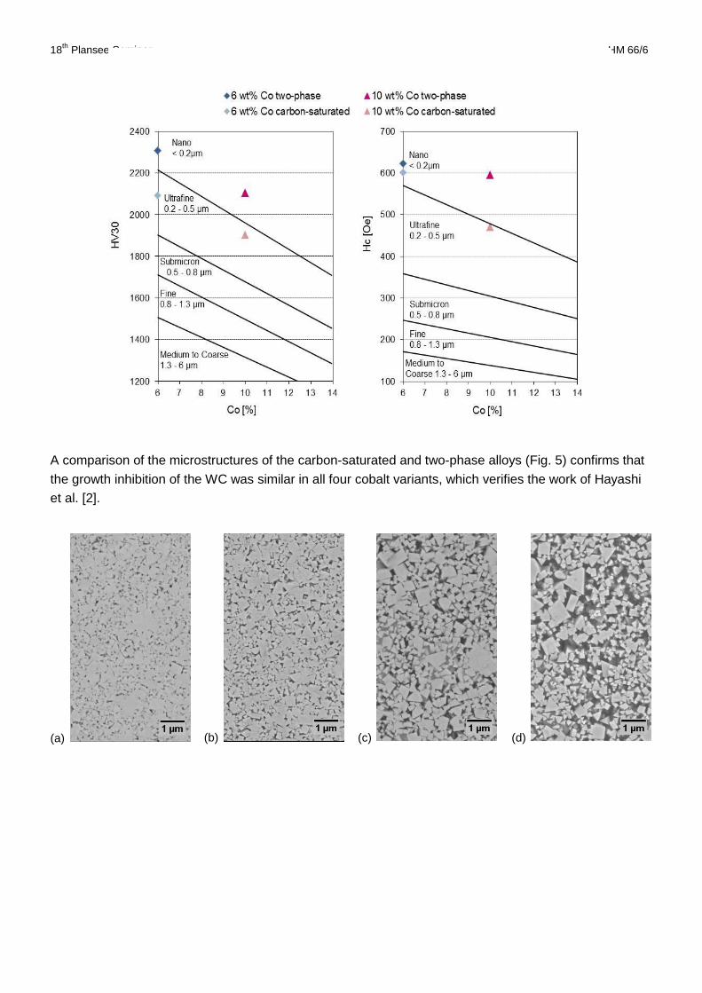
(near)-nanosized microstructure (< 0.2 µm). This is also depicted in Fig. 4, which shows the HV30 vs.
wt% Co and the HC vs. wt% Co relation for alloys with 6 wt% up to 14 wt% Co.
Table 2: Grain size analysis done by linear intercept method using FESEM-BSE images (x50k); carbon-saturated samples are
marked with * after the sample name.
SAMPLE average
intercept
length [µm]
mean grain
diameter
[µm]
SAMPLE average
intercept
length [µm]
mean grain
diameter
[µm]
HM6* 0.179 0.215 HM6 0.132 0.162
HM10* 0.189 0.228 HM10 0.147 0.178
HM20* 0.196 0.237 HM20 0.160 0.193
HM30* 0.185 0.223 HM30 0.168 0.202
18th
Plansee Seminar HM 66/6
Figure 4: Presentation of Hardness (HV30) versus Cobalt content (left) and Coercivity versus Cobalt content (right) for two-
phase and carbon saturated alloys; the respective terms indicate WC grain sizing according to the German Hartmetallverband
(re-drawn).
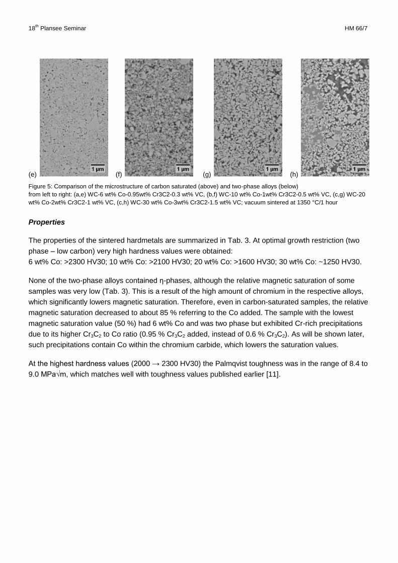
A comparison of the microstructures of the carbon-saturated and two-phase alloys (Fig. 5) confirms that
the growth inhibition of the WC was similar in all four cobalt variants, which verifies the work of Hayashi
et al. [2].
(a) (b) (c) (d)
18th
Plansee Seminar HM 66/7
Properties
The properties of the sintered hardmetals are summarized in Tab. 3. At optimal growth restriction (two
phase – low carbon) very high hardness values were obtained:
6 wt% Co: >2300 HV30; 10 wt% Co: >2100 HV30; 20 wt% Co: >1600 HV30; 30 wt% Co: ~1250 HV30.
None of the two-phase alloys contained η-phases, although the relative magnetic saturation of some
samples was very low (Tab. 3). This is a result of the high amount of chromium in the respective alloys,
which significantly lowers magnetic saturation. Therefore, even in carbon-saturated samples, the relative
magnetic saturation decreased to about 85 % referring to the Co added. The sample with the lowest
magnetic saturation value (50 %) had 6 wt% Co and was two phase but exhibited Cr-rich precipitations
due to its higher Cr3C2 to Co ratio (0.95 % Cr3C2 added, instead of 0.6 % Cr3C2). As will be shown later,
such precipitations contain Co within the chromium carbide, which lowers the saturation values.
At the highest hardness values (2000 → 2300 HV30) the Palmqvist toughness was in the range of 8.4 to
9.0 MPa√m, which matches well with toughness values published earlier [11].
(e) (f) (g) (h)
Figure 5: Comparison of the microstructure of carbon saturated (above) and two-phase alloys (below)
from left to right: (a,e) WC-6 wt% Co-0.95wt% Cr3C2-0.3 wt% VC, (b,f) WC-10 wt% Co-1wt% Cr3C2-0.5 wt% VC, (c,g) WC-20
wt% Co-2wt% Cr3C2-1 wt% VC, (c,h) WC-30 wt% Co-3wt% Cr3C2-1.5 wt% VC; vacuum sintered at 1350 °C/1 hour
18th
Plansee Seminar HM 66/8
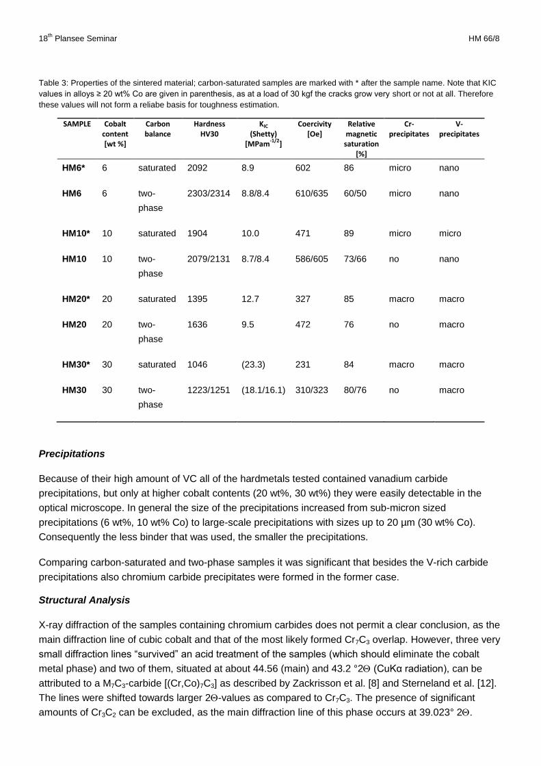
Table 3: Properties of the sintered material; carbon-saturated samples are marked with * after the sample name. Note that KIC
values in alloys ≥ 20 wt% Co are given in parenthesis, as at a load of 30 kgf the cracks grow very short or not at all. Therefore
these values will not form a reliabe basis for toughness estimation.
SAMPLE Cobalt content [wt %]
Carbon balance
Hardness HV30
KIC (Shetty)
[MPam-1/2
]
Coercivity [Oe]
Relative magnetic
saturation [%]
Cr-precipitates
V-precipitates
HM6* 6 saturated 2092 8.9 602 86 micro nano
HM6 6 two-
phase
2303/2314 8.8/8.4 610/635 60/50 micro nano
HM10* 10 saturated 1904 10.0 471 89 micro micro
HM10 10 two-
phase
2079/2131 8.7/8.4 586/605 73/66 no nano
HM20* 20 saturated 1395 12.7 327 85 macro macro
HM20 20 two-
phase
1636 9.5 472 76 no macro
HM30* 30 saturated 1046 (23.3) 231 84 macro macro
HM30 30 two-
phase
1223/1251 (18.1/16.1) 310/323 80/76 no macro
Precipitations
Because of their high amount of VC all of the hardmetals tested contained vanadium carbide
precipitations, but only at higher cobalt contents (20 wt%, 30 wt%) they were easily detectable in the
optical microscope. In general the size of the precipitations increased from sub-micron sized
precipitations (6 wt%, 10 wt% Co) to large-scale precipitations with sizes up to 20 µm (30 wt% Co).
Consequently the less binder that was used, the smaller the precipitations.
Comparing carbon-saturated and two-phase samples it was significant that besides the V-rich carbide
precipitations also chromium carbide precipitates were formed in the former case.
Structural Analysis
X-ray diffraction of the samples containing chromium carbides does not permit a clear conclusion, as the
main diffraction line of cubic cobalt and that of the most likely formed Cr7C3 overlap. However, three very
small diffraction lines “survived” an acid treatment of the samples (which should eliminate the cobalt
metal phase) and two of them, situated at about 44.56 (main) and 43.2 °2 (CuKα radiation), can be
attributed to a M7C3-carbide [(Cr,Co)7C3] as described by Zackrisson et al. [8] and Sterneland et al. [12].
The lines were shifted towards larger 2-values as compared to Cr7C3. The presence of significant
amounts of Cr3C2 can be excluded, as the main diffraction line of this phase occurs at 39.023° 2.
18th
Plansee Seminar HM 66/9
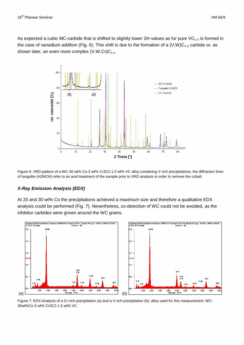
As expected a cubic MC-carbide that is shifted to slightly lower 2-values as for pure VC1-X is formed in
the case of vanadium addition (Fig. 6). This shift is due to the formation of a (V,W)C1-X carbide or, as
shown later, an even more complex (V,W,Cr)C1-x.
Figure 6: XRD-pattern of a WC-30 wt% Co-3 wt% Cr3C2-1.5 wt% VC alloy containing V-rich precipitations; the diffraction lines
of tungstite (H2WO4) refer to an acid treatment of the sample prior to XRD analysis in order to remove the cobalt.
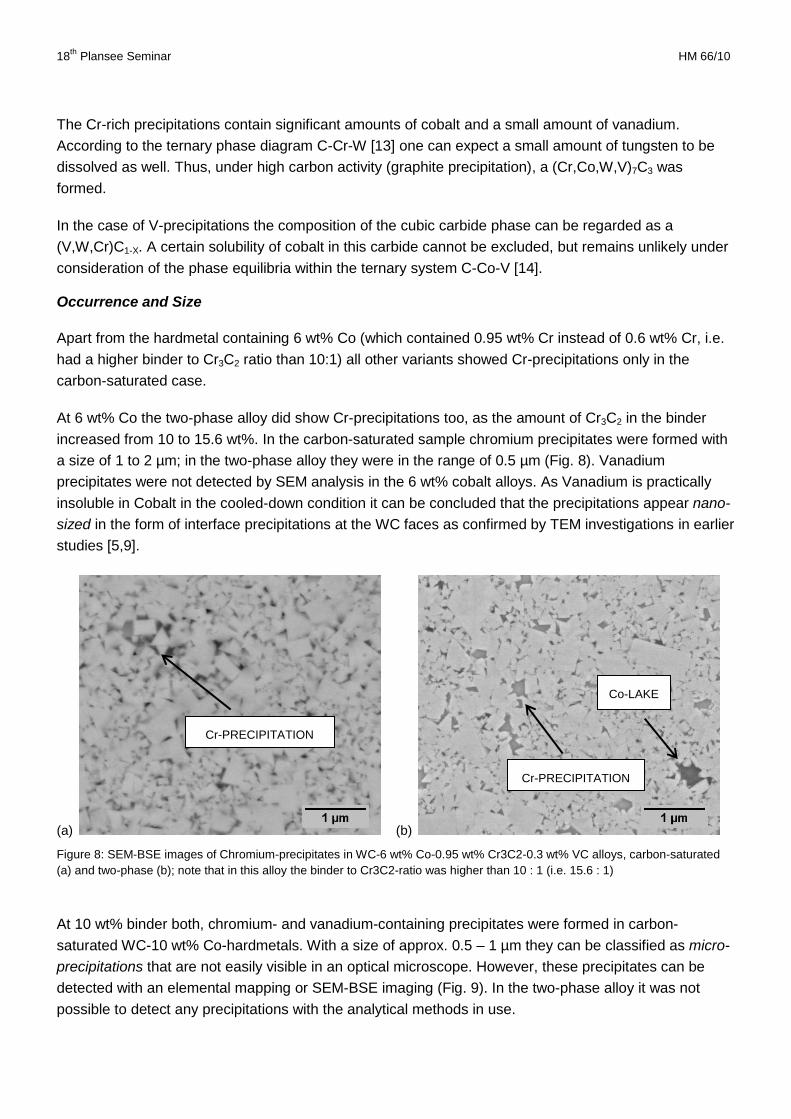
X-Ray Emission Analysis (EDX)
At 20 and 30 wt% Co the precipitations achieved a maximum size and therefore a qualitative EDX
analysis could be performed (Fig. 7). Nevertheless, co-detection of WC could not be avoided, as the
inhibitor carbides were grown around the WC grains.
(a) (b)
Figure 7: EDX-Analysis of a Cr-rich precipitation (a) and a V-rich precipitation (b); alloy used for this measurement: WC-
30wt%Co-3 wt% Cr3C2-1.5 wt% VC
18th
Plansee Seminar HM 66/10
The Cr-rich precipitations contain significant amounts of cobalt and a small amount of vanadium.
According to the ternary phase diagram C-Cr-W [13] one can expect a small amount of tungsten to be
dissolved as well. Thus, under high carbon activity (graphite precipitation), a (Cr,Co,W,V)7C3 was
formed.
In the case of V-precipitations the composition of the cubic carbide phase can be regarded as a
(V,W,Cr)C1-X. A certain solubility of cobalt in this carbide cannot be excluded, but remains unlikely under
consideration of the phase equilibria within the ternary system C-Co-V [14].
Occurrence and Size
Apart from the hardmetal containing 6 wt% Co (which contained 0.95 wt% Cr instead of 0.6 wt% Cr, i.e.
had a higher binder to Cr3C2 ratio than 10:1) all other variants showed Cr-precipitations only in the
carbon-saturated case.
At 6 wt% Co the two-phase alloy did show Cr-precipitations too, as the amount of Cr3C2 in the binder
increased from 10 to 15.6 wt%. In the carbon-saturated sample chromium precipitates were formed with
a size of 1 to 2 µm; in the two-phase alloy they were in the range of 0.5 µm (Fig. 8). Vanadium
precipitates were not detected by SEM analysis in the 6 wt% cobalt alloys. As Vanadium is practically
insoluble in Cobalt in the cooled-down condition it can be concluded that the precipitations appear nano-
sized in the form of interface precipitations at the WC faces as confirmed by TEM investigations in earlier
studies [5,9].
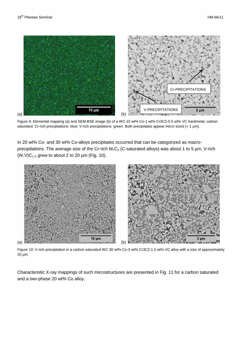
(a) (b)
Figure 8: SEM-BSE images of Chromium-precipitates in WC-6 wt% Co-0.95 wt% Cr3C2-0.3 wt% VC alloys, carbon-saturated
(a) and two-phase (b); note that in this alloy the binder to Cr3C2-ratio was higher than 10 : 1 (i.e. 15.6 : 1)
At 10 wt% binder both, chromium- and vanadium-containing precipitates were formed in carbon-
saturated WC-10 wt% Co-hardmetals. With a size of approx. 0.5 – 1 µm they can be classified as micro-
precipitations that are not easily visible in an optical microscope. However, these precipitates can be
detected with an elemental mapping or SEM-BSE imaging (Fig. 9). In the two-phase alloy it was not
possible to detect any precipitations with the analytical methods in use.
Cr-PRECIPITATION
Cr-PRECIPITATION
Co-LAKE
18th
Plansee Seminar HM 66/11
(a) (b)
Figure 9: Elemental mapping (a) and SEM-BSE image (b) of a WC-10 wt% Co-1 wt% Cr3C2-0.5 wt% VC hardmetal, carbon
saturated. Cr-rich precipitations: blue; V-rich precipitations: green. Both precipitates appear micro sized (< 1 µm).
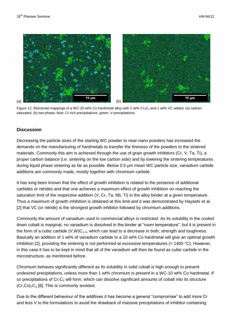
In 20 wt% Co- and 30 wt% Co-alloys precipitates occurred that can be categorized as macro-
precipitations. The average size of the Cr-rich M7C3 (C-saturated alloys) was about 1 to 5 µm, V-rich
(W,V)C1-X grew to about 2 to 20 µm (Fig. 10).
(a) (b)
Figure 10: V-rich precipitation in a carbon-saturated WC-30 wt% Co-3 wt% Cr3C2-1.5 wt% VC alloy with a size of approximately
20 µm.
Characteristic X-ray mappings of such microstructures are presented in Fig. 11 for a carbon saturated
and a two-phase 20 wt% Co alloy.
Cr-PRECIPITATIONS
V-PRECIPITATIONS
18th
Plansee Seminar HM 66/12
(a) (b)
Figure 11: Elemental mappings of a WC-20 wt% Co hardmetal alloy with 2 wt% Cr3C2 and 1 wt% VC added. (a) carbon-
saturated, (b) two-phase; blue: Cr-rich precipitations, green: V-precipitations.
Discussion
Decreasing the particle sizes of the starting WC powder to near-nano powders has increased the
demands on the manufacturing of hardmetals to transfer the fineness of the powders to the sintered
materials. Commonly this aim is achieved through the use of grain growth inhibitors (Cr, V, Ta, Ti), a
proper carbon balance (i.e. sintering on the low carbon side) and by lowering the sintering temperatures
during liquid phase sintering as far as possible. Below 0.5 µm mean WC particle size, vanadium carbide
additions are commonly made, mostly together with chromium carbide.
It has long been known that the effect of growth inhibition is related to the presence of additional
carbides or nitrides and that one achieves a maximum effect of growth inhibition on reaching the
saturation limit of the respective addition (V, Cr, Ta, Nb, Ti) in the alloy binder at a given temperature.
Thus a maximum of growth inhibition is obtained at this limit and it was demonstrated by Hayashi et al.
[2] that VC (or nitride) is the strongest growth inhibitor followed by chromium additions.
Commonly the amount of vanadium used in commercial alloys is restricted. As its solubility in the cooled
down cobalt is marginal, no vanadium is dissolved in the binder at “room temperature”, but it is present in
the form of a cubic carbide (V,W)C1-X, which can lead to a decrease in both, strength and toughness.
Basically an addition of 1 wt% of vanadium carbide to a 10 wt% Co hardmetal will give an optimal growth
inhibition [2], providing the sintering is not performed at excessive temperatures (> 1400 °C). However,
in this case it has to be kept in mind that all of the vanadium will then be found as cubic carbide in the
microstructure, as mentioned before.
Chromium behaves significantly different as its solubility in solid cobalt is high enough to prevent
undesired precipitations, unless more than 1 wt% chromium is present in a WC-10 wt% Co hardmetal. If
so precipitations of Cr7C3 will form, which can dissolve significant amounts of cobalt into its structure
(Cr,Co)7C3 [8]. This is commonly avoided.
Due to the different behaviour of the additives it has become a general “compromise” to add more Cr
and less V to the formulations to avoid the drawback of massive precipitations of inhibitor containing
18th
Plansee Seminar HM 66/13
phases, which decrease strength. Such a compromise, for example, is to add 1 wt% Cr3C2 and 0.3 wt%
of VC to a 10 wt% Co hardmetal (or 0.6 wt% Cr3C2 and 0.18 wt VC to a 6 wt% Co hardmetal). In this
case most of the chromium will remain in solid solution and vanadium will form small precipitates of
(V,W)C, which will not decrease the strength below a critical value.
However, as the WC particles are becoming finer and finer, even this compromise cannot restrict the
growth to the greatest possible extent. Adding higher amounts of grain growth inhibitors becomes
necessary to further increase hardness for an optimal use of the potential of these extremely fine WC
powders with individual particle sizes in the range of 50 to 200 nm.
Therefore the inhibitor additions in the formulations of this work were extended to a Co/Cr3C2/VC =
10/1/0.3 to a 10/1/0.5 ratio. In addition, the sintering temperature was reduced to 1350°C, which on one
hand is low enough to minimize the WC growth, but on the other hand high enough to render true liquid
phase sintering also in low carbon materials.
The results of our study demonstrate that under the conditions described above, a significantly higher
hardness is obtained as compared to conventional additions [15] but the formation of inhibitor containing
phases could not be avoided.
Cr-rich precipitations occurred at high carbon activity only (graphite formation), with the exception of one
case where an even higher Cr-addition related to the amount of cobalt was implemented (our 6 wt% Co
hardmetal contained 0.95 wt% Cr3C2 instead of 0.6 wt% Cr3C2). V-rich precipitations formed in all of the
variants studied, but remarkably no precipitates were detectable by optical microscopy or SEM imaging
in case of the 6 wt% Co alloy. Also X-ray mapping did not indicate any non-uniform vanadium distribution
within the two-phase alloy. These results indicate that the size of the (V,W)C precipitations is below 100
nm and they cannot be detected by the analytical methods in use.
For compositions with a higher Co content (10, 20 and 30 wt% Co) the size of the precipitations
increased from sub-micron to micron sized (10 wt% Co) up to 20 µm (30 wt% Co). At 20 to 30 wt%, the
cubic carbide phase precipitated onto the WC grains and grew around them pushing the cobalt phase
apart, so that finally large intergrown carbide areas were formed (see Fig. 10).
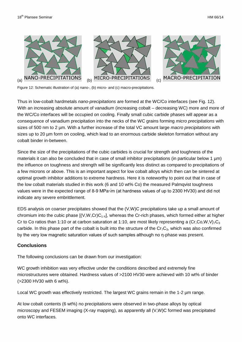
The difference in sizes of the cubic carbides are schematically demonstrated in Fig. 12.
At low binder contents (6 wt% Co) the amount of vanadium added was very low relative to the WC matrix
(the weight ratio of WC to VC is only 0.002 %), and increased at 10 wt% Co to a WC/VC ratio of 0.006,
at 20 wt% Co to 0.013, and finally at 30 wt% Co to 0.023. Thus at the same cobalt to inhibitor ratio (as
intended to compare the growth inhibition effect) the absolute amount of vanadium (and chromium) was
increasing, which increased the volume ratio of the precipitates compared to the WC.
In case of chromium the situation is different, as all or most of the chromium was dissolved in the binder
(note that Cr-segregations onto the WC/Co interfaces cannot be excluded). However, in carbon-
saturated hardmetals Cr-precipitations were formed. In this case the volume of Cr-rich precipitations was
increasing with increasing cobalt content as well.
18th
Plansee Seminar HM 66/14
(a) (b) (c)
Figure 12: Schematic illustration of (a) nano-, (b) micro- and (c) macro-precipitations.
Thus in low-cobalt hardmetals nano-precipitations are formed at the WC/Co interfaces (see Fig. 12).
With an increasing absolute amount of vanadium (increasing cobalt – decreasing WC) more and more of
the WC/Co interfaces will be occupied on cooling. Finally small cubic carbide phases will appear as a
consequence of vanadium precipitation into the necks of the WC grains forming micro precipitations with
sizes of 500 nm to 2 µm. With a further increase of the total VC amount large macro precipitations with
sizes up to 20 µm form on cooling, which lead to an enormous carbide skeleton formation without any
cobalt binder in-between.
Since the size of the precipitations of the cubic carbides is crucial for strength and toughness of the
materials it can also be concluded that in case of small inhibitor precipitations (in particular below 1 µm)
the influence on toughness and strength will be significantly less distinct as compared to precipitations of
a few microns or above. This is an important aspect for low cobalt alloys which then can be sintered at
optimal growth inhibitor additions to extreme hardness. Here it is noteworthy to point out that in case of
the low cobalt materials studied in this work (6 and 10 wt% Co) the measured Palmqvist toughness
values were in the expected range of 8-9 MPa√m (at hardness values of up to 2300 HV30) and did not
indicate any severe embrittlement.
EDS analysis on coarser precipitates showed that the (V,W)C precipitations take up a small amount of
chromium into the cubic phase [(V,W,Cr)C1-X], whereas the Cr-rich phases, which formed either at higher
Cr to Co ratios than 1:10 or at carbon saturation at 1:10, are most likely representing a (Cr,Co,W,V)7C3
carbide. In this phase part of the cobalt is built into the structure of the Cr7C3, which was also confirmed
by the very low magnetic saturation values of such samples although no ƞ-phase was present.
Conclusions
The following conclusions can be drawn from our investigation:
WC growth inhibition was very effective under the conditions described and extremely fine
microstructures were obtained. Hardness values of >2100 HV30 were achieved with 10 wt% of binder
(>2300 HV30 with 6 wt%).
Local WC growth was effectively restricted. The largest WC grains remain in the 1-2 µm range.
At low cobalt contents (6 wt%) no precipitations were observed in two-phase alloys by optical
microscopy and FESEM imaging (X-ray mapping), as apparently all (V,W)C formed was precipitated
onto WC interfaces.
18th
Plansee Seminar HM 66/15
At higher cobalt content (10 wt%) the amount of (V,W)C in the microstructure increased, and micro-
crystalline precipitations were observed (0.5 to 1 µm)
At 20 and 30 wt% cobalt the amount of V-rich precipitates further increased and precipitates occurred
with intergrown WC/(V,W)C areas with sizes of up to 20 µm. In these areas no cobalt binder was
present.
Thus the size and amount of (V,W)C increases with increasing cobalt content in the nominal composition
(6→10→20→30 wt%) from nano-sized interface precipitations, to micro- and finally macro-sized
precipitations.
The growth inhibition effect is about the same for all binder variants, which confirms the assumption that
at the same binder:Cr3C2/VC ratio the growth restriction is about equal.
At the ratio of Co/Cr3C2/VC of 10/1/0.5 chromium precipitations also occurred in carbon-saturated
hardmetals. The amount and size of these precipitations also increased with increasing binder content.
No Cr-precipitations were observed in two phase alloys.
If the ratio is increased to Co/Cr3C2/VC = 10/1.5/0.5, chromium carbides also formed in two phase
hardmetals.
The chromium carbide can be regarded as a (Cr,Co,W,V)7C3 carbide. If such carbides are formed in two
phase hardmetals, they lower the magnetic saturation of the materials due to the build-in of cobalt into
the chromium carbide.
The vanadium-rich phase represents a cubic mixed-crystal carbide with a composition of (V,W,Cr)1-X.
The work also points out that at low binder contents (< 10 wt% Co) the increased amount of vanadium
strongly strengthens the inhibition process without leading to a distinct decrease in toughness and most
likely also in strength. This is due to the small size of the vanadium precipitations which are uniformly
distributed over the microstructure.
Acknowledgement
The authors are grateful to Dr. A. Bicherl and Dr. A. Bock of Wolfram Bergbau und Hütten AG for
supplying the WC powder for this investigation.
References
1. Kornwachstum und Kornwachstumshemmung in Hartmetallen - Eine ganzheitliche Betrachtung.
W.D. Schubert, [Hrsg.] Fachverband Pulvermetallurgie. 23. Hagener Symposium. ISBN 3-933842-79-
4, p. 117-139 (2004).
2. Effects of Addition Carbides on the Grain Size of WC-Co Alloys. K. Hayashi, Y. Fuke, H. Suzuki., J.
Jpn. Soc. Powder Powder Met., Bd. 19, S. 67-71 (1972).
3. Morphology of Vanadium Carbide in Submicron Hardmetals. A. Egami, M. Ehira, M. Machida.
Reutte : Proceedings of the 13th International Plansee Seminar. Bd. 3, p. 639-648 (1993).
18th
Plansee Seminar HM 66/16
4. Sintering Behaviour of VC-doped Micro-Grained Cemented Carbide. T. Taniuchi, K. Okada, T.
Tanase. Reutte : Proceedings of the 14th International Plansee Seminar. Bd. 2, p. 644-657 (1997).
5. Formation of (W,V)Cx layers at the WC/Co interfaces in the WC-doped WC-Co cemented carbide. I.
Sugiyama, Y. Mizumukai, T. Taniuchi, K. Okada, F. Shirase, T. Tanase, Y. Ikuhara, T.
Yamamoto. Int. J. Refract. Met. Hard Mater. 30, p. 185-187 (2012).
6. Determination of the composition range suitable to the formation of WC-(V,W)Cx-Co materials. E.G.
Obbard, S. Luyckx, S. Hamar-Thibault, C.H. Allibert., Int. J. Refract. Met. Hard Mater. 19 p. 349-
357 (2001).
7. The structure and strength of Micro-grained WC-Co Hard Metals. H. Suzuki, K. Tokumoto.
J. Jpn. Soc. Powder Powder Met., S. 152-157 (1985).
8. WC-Co based cemented carbides with large Cr3C2 additions. J. Zackrisson, B. Jansson, G.S.
Uphadyaya, H.-O. Andrén., Int. J. Refract. Met. Hard Mater. 16 p. 417-422 (1998).
9. HREM characterisation of VC in doped WC-Co Cermets. S. Lay, S. Hamar-Thibault, A. Lackner.
Reutte : Proceedings of the 15th International Plansee Seminar. Bd. 2, p. 106-118 (2001).
10. Development of High Performance Carbide Tools. Tanase, T. J. Jpn. Soc. Powder Powder Met. 54
p. 243-250 (2007).
11. Hardness to toughness relationship of fine-grained WC-Co hardmetals. W.D. Schubert, H.
Neumeister, G. Kinger, B.Lux, Int. J. Refr. Metals & Hard Mater. 16 133-142 (1998).
12. Investigation of Co (Cr,Co)7C3-fcc-Graphite Equilibrium in the Temperature Interval 1373 to 1473 K.
T. Sterneland, A. Markström, S. Norgren, R.E. Aune, S. Seetharaman, Met. TRANS A, 37 A,
3023-3028 (2006).
13. C-Cr-W: Handbook of Ternary Alloy Phase Diagrams, ASM International, Vol.5, page 6686 (1995).
14. C-Co-V: Handbook of Ternary Alloy Phase Diagrams, ASM International, Vol.5, page 6583 (1995).
15. WC grain growth during the early stages of sintering. A. Adorjan, W.D. Schubert, A. Bock, A.
Schön, B. Zeiler, Intern. J. of Refract. Met. Hard Mater. 24 p. 265-373 (2006).