Embed Size (px)
Citation preview
Deift University of TechnologyShip Hydromechanics Laboratory
LibraryMekelweg 2- 2628 CD Delft
The NetherlandsPhone: 3115 78673 - Fax: 3115 781835
On the Heat Transfer Coefficients of Cylindrical Bodies (III)'
T. TsUBOUCHI and S. SATÖ
Synopsis
In many investigations hitherto made, the heat transfer coefficients of thecylindrical surface free from the end effect or the mean heat transfer coefficientsover the whole surface of a cylindrical body have been measured, but have scarcely
been measured those of individial surface affected by the other surface of a body.In the present study, we have measured the local and the mean heat transfercoefficients of the vertical end surface and the horizontal cylindrical surface ofcircular cylinder which is located in the still air horizontally, by means of "thetemperature boundary layer method" together with the usual "heat quantitymethod". The results of experiment are expressed in the experimental formulaeon each part of cylinder and are compared with the conventional formulae of thevertical plates and the horizontal cylinders.
1. Introduction
In the previous papers Cl), we had measured the heat transfer coefficients of theupper or lower end surfaces of vertical cylinders, and pointed out the remarkablediscrepancy from the case of usual horizontal plates.
In this paper, as the successive report, we have measured the heat transfercoefficient of vertical end surface of a circular cylinder which is located in thestill air horizontally. In many investigations about the heat transfer arround thehorizontal cylinders, measurements have been made on the cylindrical surfacewith no influence of end effect, or the mean heat transfer coefficient over thewhole surface of a cylinder involving the end effect. Consequently the estimationof the heat transfer arround the cylinder of finite length is not yet evident.For this point of view, we have measured the distribution of the local and themean heat transfer coefficient, and compared them with the ordinally formulaeof the vertical plates or the horizontal cylinders (2).
Report No. 89 (in European language) of the Institute of High Speed Mechanics,Tohoku University. This report was read before the 33rd General Meeting of theJapan Society of Mechanical Engineers, on April 3, 1956.Professor of Thoku University.Research Assistant of Töhoku University.
11) Numbers in parentheses refer to the Bibliography at the end of the paper.
136 Rep. Inst. High Sp. Mech., Japan, Vol. 9 (1958), No. 89
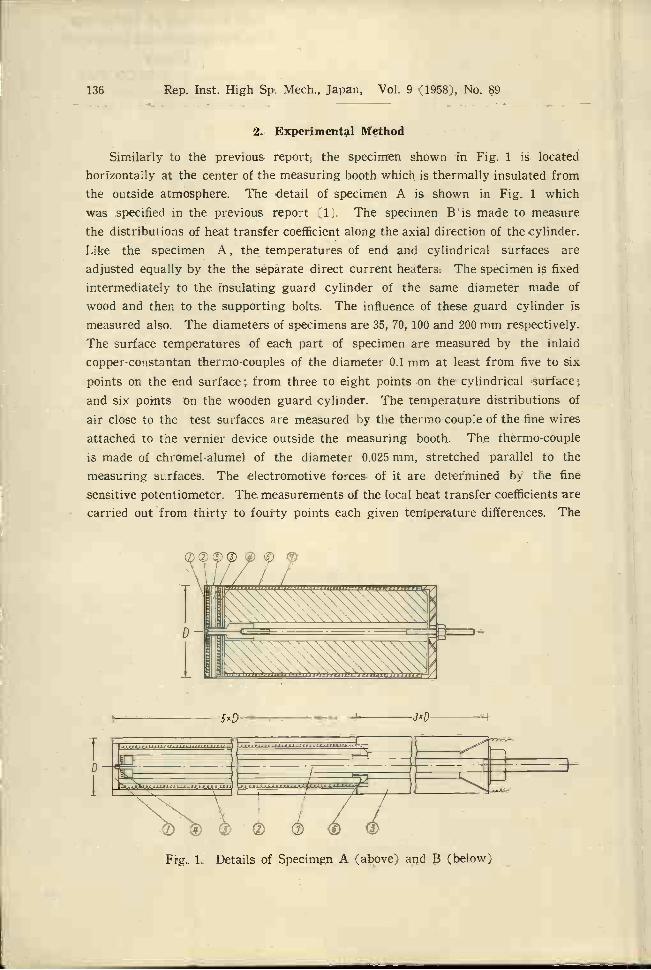
Similarly to the previous report, the specimen shown in Fig. i is locatedhorizontally at the center of the measuring booth which is thermally insulated fromthe outside atmosphere. The detail of specimen A is shown in Fig. i which
was specified in the previous report (1). The specimen B is made to measurethe distributions of heat transfer coefficient along the axial direction of the cylinder.Like the specimen A, the temperatures of end and cylindrical surfaces areadjusted equally by the the separate direct current heaters. The specimen is fixedintermediately to the insulating guard cylinder of the same diameter made ofwood and then to the supporting bolts. The influence of these guard cylinder ismeasured also. The diameters of specimens are 35, 70, 100 and 200 mm respectively.The surface temperatures of each part of specimen are measured by the inlaidcopper-constantan thermo-couples of the diameter 0.1 mm at least from five to sixpoints on the end surface; from three to eight points on the cylindrical surface;and six points on the wooden guard cylinder. The temperature distributions ofair close to the test surfaces are measured by the thermo-couple of the fine wiresattached to the vernier device outside the measuring booth. The thermo-coupleis made of chromel-alumel of the diameter 0.025 mm, stretched parallel to themeasuring surfaces. The electromotive forces of it are determined by the finesensitive potentiometer. The measurements of the local heat transfer coefficients arecarried out from thirty to fourty points each given temperature differences. The
o o
1'tjI.
2. Experimental Method
Fig. 1. Details of Specimen A (above) and B (below)
5xD 3xD
T. TSUBOTJCHI and S. SAT: Heat Transfer Coefficients (III) 137
temperature fluctuations during the measurrernent are adjusted so as to bewithin i %.
If we denote by Q Kcal/h the convective heat quantity from the hot surfacesof the temperature TW0C and of the area Fm' to surrounding fluid of the tem-perature Ta°C, the surface heat transfer coefficient a, Kcal/m2h°C is defined asfollows
= F. AT'
where AT T,, - T. Now, if the temperature of ambient fluid at the distancex ni from the surface is denoted by 0°c, dQ,, is equal to the quantity of heat conduc-tion through the boundary layer of the area dFm2, so that
dQ2 = -)
dF,Ox £0
where X Kcal/mhC is the thermal conductivity of the fluid close to the surface.Accordingly the local heat transfer coefficient is expressed as follows
= X / 00 \AT Ox Ix=o
And the mean heat transfer coefficients ¿ Kcal/m2h°C of the end surface of acylinder (diameter Dm) is expressed by integrating Eq. (1) for the whole surfaceas follows
I)!2
4Ç x( )dFo Ox o-
r D2 4 T
where 7' is the mean temperature difference on the whole area of end surface.If we denote by r the distance of any point of end surface f rom the center, AT
is expressed by
This method of obtaining the heat transfer coefficient is called the temperatureboundary method.
On the other hand, the value of Q,, can be decided by the measurement offollowing heat quantities
= Q - (Q ± Q + Q,OC ± Qs!? + Qe), (4)
ATrdr. (3)
138 Rep. Inst. High Sp. Mech., Japan, Vol. 9 (1958), No. 89
where QT is the total heat quantity, QR the radiation heat loss from the testsurface, QE the conductive loss to the axial direction in the interior of the cylin-drical body; Q, Q80 the radiation and convective heat loss from the side surfacerespectively; and Q is the conductive loss from the leading wiies of heating coils.It is a matter of course, Q is reduced to zero by the adjustment of the heatingcurrent of balancing heating coil in the case of specimen A. And the radiationconstant of the measuring surface is adopted from the result of previous paperswhich is determined by comparing the temperature boundary method with heatquantity method in case of downward facing end surface. 1f C and C arethe coefficients of radiation of copper end surface and white paper of side surface.These values are decided after all as C,,=1.1 and C=4.6 (3). Q can be neglectedby the same reason with QE. We call this usual method "heat quantity mothod"corresponding to the above mentioned method. In this case the mean heat transfercoefficients are decided directly as follows
4Qc7tD2 4T
As for the case of specimen B, at the distance z from the end surface, the meanheat transfer coefficient arround the cylinder is expressed as
=--c: a(0)dO, (.6 )
where e is the angle measured from the lowest point at the section z of a circularcylinder, and a (0) is the local heat transfer coefficient at a point (z, O). In thiscase, the temperature distributions of the boundary layer are measured on theradial directions by means of the above mentioned thermo-couple attached to therotationable varnier device. From the test result of fluid temperature adjacent tothe testing hot surfaces beforehand, major parts of circumference have been provedto form the stable temperature boundary layer except the vicinity of the upperend. The quantity of heat which is transfered from the upper unstable part isestimated about 10 % of the whole, so that if we repeat the measurement manytimes at this part we may have sufficient accuracy of test results.
3. Experimental Results
Test cylinder is placed horizontally and its end surfaces are located vertically.The temperatures in the boundary layer are meausred at the various parts of thecylinder and are shown in Fig. 2. The comparisons of the mean heat transfercoefficients obtained by the heat quantity method and that by the temperatureboundary method are shown in Fig. 2 which show good agreements. The measure-ments of local heat transfer coefficient cx, on the end surface have repeated densely
(5)

T. TSUBOUCHI and S. SAT: Heat Transfer Coefficients (III) 139
PhIiiçe,
8 ô /8 12 Ic
Fig. 3 (a). D=7Omm, T=143.O°C
Fig. 2. An Example of Relation of Heat Quantities and Comparison betweenthe Heat Quantity Method and the Temperature Boundary
Layer Method
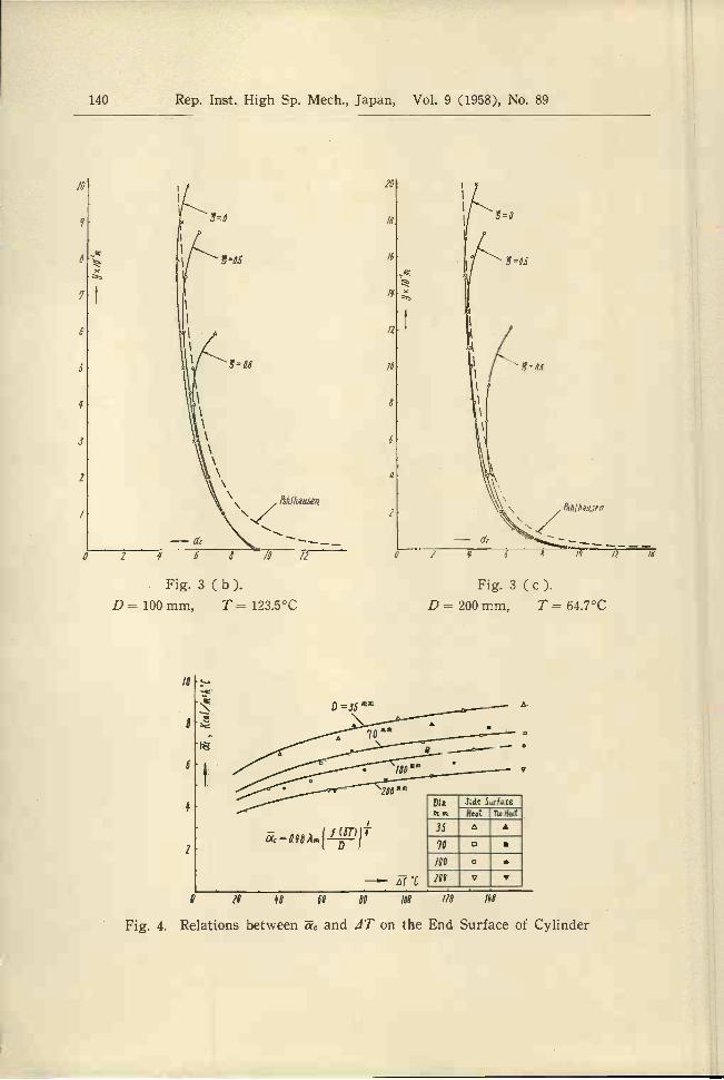
Fig. 3 (a), (b) and (c).Distributions of a, for VerticalDirection at Various Parts ofEnd Surface and Comparison ofThem with Those of VerticalPlate
/0
o
140 Rep. Inst. High Sp. Mech., Japan, Vol. 9 (1958), No. 89
Fig. 3(b).D -= loo mm, T = 123.5°C
IC
8
6
z
Ihuse
Q 70 80 60 60 100 /20 /80
Fig. 4. Relations between and 41' on the End Surface of Cylinder
Fig. 3 (c).D= 200mm, T= 64.7°C
- -/0 /2 /4
16
/6
/6
17
16 I
i / \ lOo
'2o 6 6
T. TSUBOUCHI and S. SATii: Heat Transfer Coefficients (III) 141
n the neighbourhood of circumference especially. For each test piece, we meas-ured 30-40 points at each temperature difference. In Fig. 4 the some examplesof vertical distributions of heat transfer coefficient a of end surfaces are plottedfor three values of parameter E, which is the distance from the center of verticalstrip. For comparison, Pohlhausen's theoretical formula (4 which is derived onthe basis of the experimetal results for vertical plates made by Schmidt andBeckmann, is plotted in dotted line as follows
0.359 Xmjf(4T)1 'yf,
-- gßmATwhere f(41') = , X.,,, ß, and g are the thermal conductivity, cubic
expansion coefficient, kinematic viscosity of air and the gravitational accerrelation
and suffix m expresses those at the temperature Tm T,,, TaEq. ( 7 ) is the
theoretical formula which is applicable to the vertical infinite plate standing atthe floor. Comparing with our case which is the case of end surface of finitecircular cylinder devided into vertical striP, we find that Pohlhausen's formulagives remarkably large value at the lower edge, and small in the neighbourhoodof upper edge. However, as the whole, it gives somewhat larger than our experi-mental values.
Fig. 4 shows the relations between the mean heat transfer coefficient and
mean temperature difference JTspecifing by Eq. ( 2 ). ¿ increases with increasingtemperature differences and decreasing diameters. Curves shown by full lines
express the following experimental formula on the end surface
- 0.48 X, D f(8)
which agree with the experimental results within maximum error about 7 %. In
this figure, the results of heat transfer coefficient of end surface with heating thecylindrical surface are also plotted but the effect of heating is not so remarkableas the case of horizontal end surfaces and can be neglected.
Then, introducing Nusselt and Grashof numbers in which the linear dimensionis the diameter D, the experimental formula is obtained in the same form withthe previous report as follows
(7)

142 Rep. Inst. High Sp. Mech., Japan, Vol. 9 (1958), No. 89
102
a
6
'3
2
10
o
6
Fig. 5. Relations between N and G on the End Surface of Cylinder
N = 0.48 Gr°25, for 10 < G,. < los. (9)
This result quite agrees with the case of vertical plate within 2 ft height bySchmidt and Beckmann (5) and the theoretical results on vertical plate by Shuga-wara and Michivoshi (6) recently, in which the linear dimension is diameter D.And if we denote a the mean heat transfer coefficient from the lowest edge tothe height D, Eq. ( 7 ) is transformed as follows
i "=-- ady (10)
This equation agrees with (9) in the same way.The results of the above mentioned vertical plate are applicable to the plate
of height D, but do not give the mean heat transfer coefficient for the wholesurface of circular plate. Now, let us assume
that this equation is able to apply to thevertical circular plate, and compare with the
case of our experiment. In Fig. 6, if wedenote the mean heat transfer coefficient of
vertical strip, we obtain as follows, from
Eq. (9)
- 048 X,{f(4T)l 1/4D1' (11)
o'
Fig. 6. Application to CircularPlate of Theory for Vertical
Plate
lEuI
'NaC450r2j-
T. TSuBOUCHI and S. SAT: Heat Transfer Coefficients (III) 143
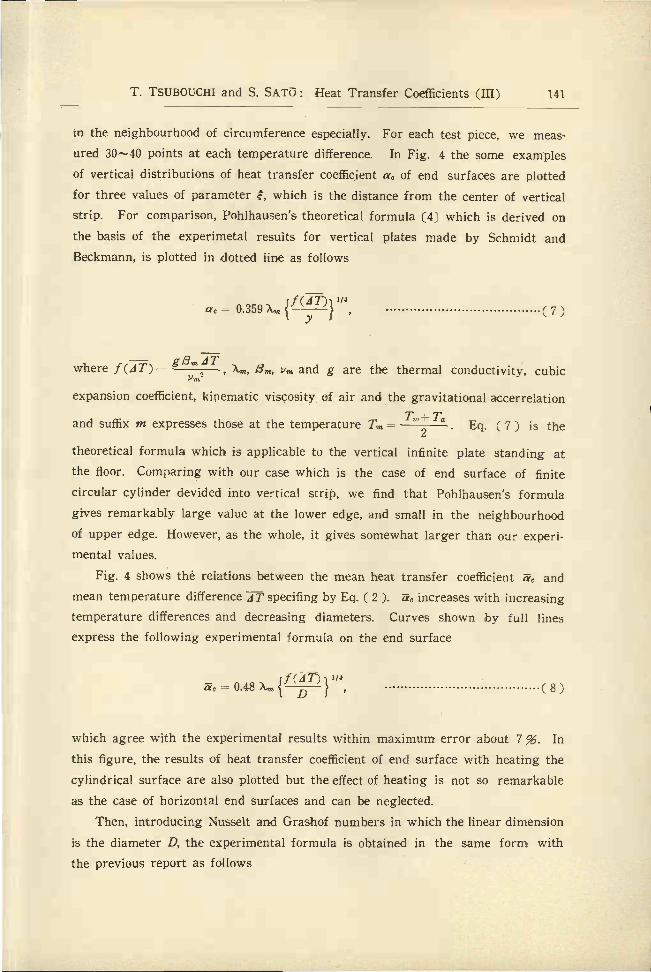
where D is the length of chord at the distance r from the center. Assuming thatthis equation satisfies with the all values of De, and introducing the parameterE, we obtain the next relation
r ED/2, De Dv'l E2. (12)
Then plotting the relations between and E for some temperature difference ofeach test pieces, we obtain the curves expressed by full line in the Fig. 7. From
these, we find the theoretical values for vertical circular plate are somewhatlarger than those of the experiment. Integrating Eq. (11) for the whole circularsurface, the mean heat transfer coefficient m in this case is obtained from thefollowing expression
D=0 AT=74.4C
Endiurace cl Cy1;drC;rcv.lar nate.
D =ioommA7=ío.0&
D=zocm 4fT=o'.rc
//I
10 iD=35".' 4T=qíß C
I
0 0.2 0. 06 ûû 10
Fig. 7. Comparison of the Local HeatTransfer Coefficient between VerticalEnd Surfaces and Circular Plates
8 (.m2_aCm = aeDedrrTh o
1.92 jf(AT)}1/4'1= Xm D (1_E2)3/8dE7t
jf(4T)1"4=0.51X.,
D f(13)
From the above equation, the caseof vertical circular plate is nearly6 % larger than the circular endsurface of horizontal cylinder. Letus express this relations by N andGr numbers as follows
N, = 0.51 Gr°4. (14)
as the linear dimension, McAdarns' equation is expressed as follows
This relation is expressed by dottedlines in Fig. 5.
There are many formulae of ver-tical plates hitherto made, such as anapproximate theory by Spuire C7, therecommended equation by McAdams8J and the others, for example.
air, if we take the height of verticalNow, putting Prandtl number P,. = 0.71 forplate

144 Rep. Inst. High Sp. Mech., Japän, Vol. 9 (1958), No. 89
N = 0.54 Gr°25. (15)
This equation, however, can not he directly compared with the case of circular endsurface for the reason of formula as the results of experiment of vertical rectan-gular plate by Saunders. But, this formula is 12.5 % larger than the theory byPohlhausen. Accordingly, the value of heat transfer coefficient on the verticalend surface of horizontal cylinder arrives at a conclusion that is somewhat smallcompared with the ordinaily vertical circular plate. Now a chain line in Fig. 5is the experimental result of circular plate made by Mr. Izumi (91. His value givestwice as large rasult that of as the ordinary experiment. It may be deduced thatthere are some errors due to the assumption of coefficient of radiation and theconductive heat loss of axial direction in his measurement depending only on theheat quantity method.
Next in determining Q in the Eq. (4) we also employed the temperatureboundary method to measure the distributions of on the cylindrical surfaceadjacent to the end surface of a cylinder. Results of these measurements are com-
pared with the ordinary distributions on the middle part of a cylinder. In Fig. 8,we give, as an example, the rela-tions between a and angle q',
/2where z indicates the axial dis-
z/O\
cJlc,Z85
tance from the end of a cylinder,and q' is the angle.
Hitherto, the investigations ofthe distribution of on the cylin-drical surface effectiess of its endhave been presented by Jodibauer(10) by means of the similar waywith us, and by Schmidt by meansof the "Schlieren" method. In thefigure, we also have plotted forcomparison the famous theoretical
results by Hermann (11 i and that
of recently presented by Merk &Prins 121. The experimental re-sults by Jodlbauer and the othershave not been compared directlyowing to dissimilar form of the
7==
'55 fie nl
¡lerA', Pr/ns
J
2
6z=0
a'0 20 «o 68 80 /00 120 /0 '58 /80
Fig. 8. Distributions of Heat Transfer coef-ficient ¿ of End and Middle Parts of
Horizontal Cylinder(D-70 mm, T=112.0C)
T. TSUBOUCHI and S. SAT3: Heat Transfer Coefficients (III) 145
dimensions of specimens. But, there is a considerably similar tendency with ours.Our experimental formula on ,. of the middle part of a cylinder is established
as follows
= 0.40 Gr°25 (16)
in the range of experiments 10 < G < 10. This formula shows a good agreementwith the experimental formula obtained from the result by Jodlbauer, and theabove mentioned theoretical result by Merk & Prins expressed as N. = 0.399 Gr'4.
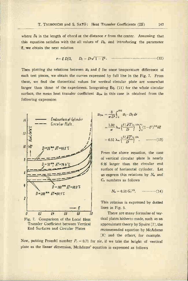
In Fig. 9, we plotted the distributions of the mean heat transfer coefficient a.,. forspecimen B on the various sections of a horizontal cylinder. From this chart,we may find the influences of the heating end surface or the insulated wooden parton the heat trasfer coefficient of a cylindrical surface. The values of m suddenlyincrease near the end of a cylinder and arrive at the end nearly 1.6 times ofthe middle parts. From this results, we know that the influences of end surface on
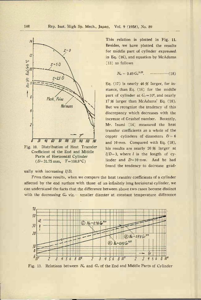
cm are confined within a distance of a diameter from the end. And Fig. 10gives examples of the distribution of ti on the circumference of the cylinder forspecimen B. From this figure it may be said that, the value of a on the middleparts of specimen A is free from the end effects. Now, comparing the curveof this distribution with the curve of on the end of cylinder, we find thelatter shows a remarkable increase in the lower half =0-90°, and nearly equalin the vicinity of upper part ço=-18O°. From the results of various experiments,
c,c=O is expressed by the following relation
2V,, = 0.76 Gr°23. (17)
/21
1c
Fig. 9. Distribution of ,,. On the Various Sections of Horizontal Cylinder(Specimen B)
/ 2 J 5 C q 8
146 Rep. Inst. High Sp. Mech., Japan, Vol. 9 (1958), No. 89
f
Z=5D+
z=2SD
70
50
30
20
10
8
10s
[lei-k, Prins
Hermana
'J
0 20 q 6V 50 100 /20 ¡f0 ¡f0 /80
Fig. 10. Distribution of Heat TransferCoefficient of the End and Middle
Parts of Horizontal Cylinder(D=31.75 mm, T=108.8°C)
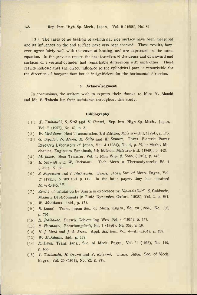
This relation is plotted in Fig. 11.
Besides, we have plotted the resultsfor middle part of cylinder expressedin Eq. (16), and equation by McAdams[13 as follows
= 0.49 G,°25. (18)
Eq. (17) is nearly 46% larger, for in-stance, than Eq. (16) for the middlepart of cylinder at Gr= 106, and nearly17 % larger than McAdams' Eq. (18).But we recognize the tendency of thisdiscrepancy which decreases with theincrease of Grashof number. Recently,Mr. Izumi Í14 measured the heattransfer coefficients as a whole of thecopper cylinders of diameters D 6
and 10 mm. Compared with Eq. (18),his results are nearly 20 % larger atl/D=3, where ¿ is the length of cy-linder and D=10 mm. And he hadfound the tendencyto decrease grad-
ually with increasing lID.From these results, when we compare the heat transfer coefficients of a cylinder
affected by the end surface with those of an infinitely long horizontal cylinder, wecan understand the facts that the difference between above two cases become distinctwith the decreasing Gr viz. smaller diamter at constant temperature difference
2 24156870e 2 3 1/56 8/0v 2 3 1/56 810Fig. 11. Relations between N6 and Gr of the End and Middle Parts of Cylinder
-----
® tVuO,qOGr'J

T. TSUBOUCHI and S. SAT5: Heat Transfer Coefficients (III) 147
which lead to larger heat transfer coefficient as the whole and become indistinctwith increasing diameter and length, which lead to smaller heat transfer coefficientas the whole. And we have clarified the same tendency for the values of 1/D inthe experiment of heat transfer for finite and inclined cylinders 151.
Then, Eq. (18) by McAdams of the heat transfer coefficients as a whole isnearly 20 % larger than Eq. (16) by our result which is reduced from the experi-ment of the local heat transfer coefficient. It may be supposed that the discrep-ancies are due to the influences of the increment of affected by the end surfaceof a finite cylinder, and also due to sensitive effect of slight air velocity in thebooth as being pointed out from the "Schlieren" method by Schmidt.
4. Conclusions
We have obtained next results from the above mentioned measurements of heattransfer coefficients from the vertical end surface and from the cylindrical surfaceof a horizontal circular cylinder due to f re convection in the range 10 < G < 10comparing with some formulae of an usual vertical plate and a horizontal cylinderhitherto made.
( 1) We have obtained the influence of end surface and end part of a horizontalcylinder and determined the circumferential distribution of ac. In the middlepart of a cylinder, this distribution is well resemble to the distribution curve bySchmidt. And the experimental formula in this case is in a good agreementwith the results by Jodlbauer and by Merk & Prins, and is expressed as follows
= 0.40 Gr°25. (19)
And the heat transfer coefficient at the end of a cylinder is remarkably largerthan hitherto made experimental formulae neglecting the end effects and is
expressed as follows
IV = 0.76 Gr°2. (20)
There is a tendency that it becomes larger with decreasing G,.. And it isapplicable to the explanation of scattering of experimental values hitherto made.
(2 The heat transfer coefficient of the end surface of a cylinder is nearly6 % smaller than the case of vertical circular plate obtained by the theory ofPohlhausen, and is expressed as follows
= 0.48 GrO2S. (21)
The values of end surfaces of horizontal cylinders are somewhat smaller thanthose of the vertical circular plates because the experimental results for verticalplates give larger value than that of theoretical value.
148 Rep. Inst. High Sp. Mech., Japan, Vol. 9 (1958), No. 89
(3) The cases of no heating of cylindrical side surface have been measuredand its influences on the end surface have also been checked. These results, how-ever, agree fairly well with the cases of heating, and are expressed in the sameequation. In the previous report, the heat transfers of the upper and downward endsurfaces of a vertical cylinder had remarkable differences with each other. These
results indicate that the direct influence to the cylindrical part is remarkable forthe direction of buoyant flow but is insignificient for the horinzontal direction.
5. Acknowledgment
In conclusions, the writers wish to express their thanks to Miss Y. Akashiand Mr. S. Takeda for their assistance throughout this study.
Bibliography
(1) T. Tsubouchi, S. Safo and II. Usanii, Rep. Inst. High Sp. Mech., Japan,Vol. 7 (1957), No. 63, p. 31.
(2) W. McAdams, Heat Transmission, 3rd Edition, McGraw.Hill, (1954), p. 175.G. Sigedai, N. Muroi, K Saitò and K. Sumita. Trans. Electric PowerRerearch Laboratory of Japan, Vol. 4 (1954), No. 4, p. 59, or Merks, Me-chanical Engineers Handbook, 5th Edition, McGraw-Hill, (1949), p. 443.M Jakob, Heat Transfer, Vol. 1, John Wily & Sons, (1949), p. 443.
[5 J E. Schmidt und W Beckmann, Tech. Mech. u. Thermodynamik, Bd. i(1930), S. 391.
(6) S. Sugawara and I. Michiyoshi, Trans. Japan Soc. of Mech. Engrs., Vol.
17 (1951), p. 109 and p. 115. In the later paper, they had obtained0.49 G°25.
[7) Result of calulation by Squire is expressed by N0.50 G,.°25. S. Goldstein,Modern Developments in Fluid Dynamics, Oxford (1938), Vol. 2, p. 641.
(8 J W. McAdams, ibid., p. 172.
[9 J R. Izumi, Trans. Japan Soc. of Mech. Engrs., Vol. 20 (1954), No. 100,
p. 791.K. Jodibauer, Forsch. Gebiete Ing.-Wes., Bd. 4 (1933), S. 157.
R. Hermann, Forschungsheft, Bd. 7 (1936), No. 319, S. 16.
(12) H J. Merk and J. A. Prins, AppI. Sci. Res., Vol. 4A, (1954), p. 207.W. McAdams, ibid., p. 177.R. Izumi, Trans. Japan Soc. of Mech. Engrs., Vol. 21 (1955), No. 119,p. 658.T. Tsubouchi, H. Usami and Y. Koizumi, Trans. Japan Soc. of Mech.Engrs., Vol. 20 (1954), No. 92, p. 245.